1
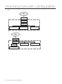
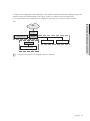
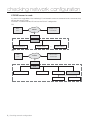
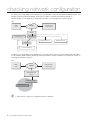
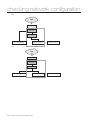
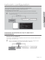
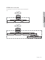
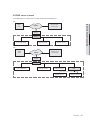
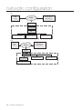
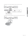
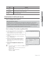
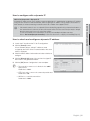
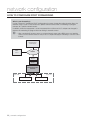
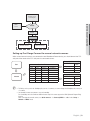
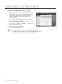
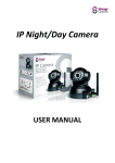
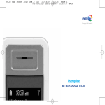
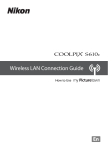
NETWORK CAMERA Network Setup Guide CONTENTS CHECKING NETWORK CONFIGURATION 3 Selecting the network type 11 Configure the network on the PC used for IP configuration Launching IP Installer Configuring IP installer values How to configure port forwarding Login Installing the program needed to launch the webviewer after connecting to network camera 3 NETWORK CONFIGURATION 11 SETUP SCREEN 37 12 19 22 27 31 37 web viewer-Network Setup checking network configuration Configure the network after checking the following. 1. Check whether to use a DDNS server. - Check whether to use a DDNS for remote monitoring from outside, or to configure the system in the form of a local network for monitoring only inside the local network. 3. Before installation, check the number and locations of network cameras and the location of the monitoring PC. 4. Check the network devices to be connected to a network camera, such as IP router/hub. 5. Check the port forwarding, ports and protocol required for establishing a camera connection path. SELECTING THE NETWORK TYPE Select the type of network that you want to configure based on the following information. If DDNS server is not used: As shown in the image below, if the monitoring PC and network camera are connected to the same router, they will have the same IP range. Install the IP installer on the local monitoring PC and use the PC for IP configuration. EX1) WAN Modem Router Local monitoring PC Network camera1 ... Network camera n ... Network camera n EX2) WAN Modem Router Local monitoring PC Network camera 1 Network camera 1 Hub ... Network camera n English _3 ● CHECKING NETWORK CONFIGURATION 2. Check whether to use a static IP or dynamic IP. checking network configuration EX3) WAN Modem Router Hub Local monitoring PC Network camera 1 ... Network camera n EX4) WAN Modem Router Hub Network camera 1 Local monitoring PC 4_ Checking network configuration ... Network camera n As shown in the image below, if the monitoring PC and network camera are connected to different routers, the network camera cannot be configured, even if the IP installer is installed in the local monitoring PC. In this case, connect the configuration PC or notebook to the router (1) to set up the network camera. EX5) ● CHECKING NETWORK CONFIGURATION WAN Modem Configuration PC Router(1) Network camera 1 ... Network camera n Router(2) Local monitoring PC M Remove the PC or laptop for IP configuration after the configuration. English _5 checking network configuration If DDNS server is used: As shown in the image below, if the monitoring PC and network camera are connected to the same router, they will have the same IP range. Install the IP Installer on the local PC and use the PC for IP configuration. EX1) DDNS Server External remote monitoring PC Internet Modem Router Local monitoring PC Network camera1 ... Network camera n EX2) DDNS Server External remote monitoring PC Internet Modem Router Local monitoring PC Network camera 1 ... Network camera n Network camera 5 6_ Checking network configuration Hub ... Network camera n EX3) DDNS Server External remote monitoring PC Internet ● CHECKING NETWORK CONFIGURATION Modem Router Hub Local monitoring PC Network camera1 ... Network camera n EX4) DDNS Server Internet External remote monitoring PC Modem Router Hub Network camera1 ... Network camera n Local monitoring PC English _7 checking network configuration As shown in the image below, if the monitoring PC and network camera are connected to different routers, the network camera cannot be configured, even if the IP installer is installed in the local monitoring PC. Connect another PC or laptop for IP configuration to router (1) and configure the network camera. EX5) DDNS Server Internet External remote monitoring PC Modem Configuration PC Router(1) Network camera 1 ... Network camera n Router(2) Local monitoring PC As shown in the image below, if the monitoring PC and the network camera are connected to the DSL/Cable/ PPPoE modem directly without connecting to the local network, connect another PC or laptop and use the PC to configure a network camera IP. EX6) DDNS Server Internet External remote monitoring PC DSL/Cable/PPPoE Modem Network camera Configuration PC M Remove the PC or laptop for IP configuration after the configuration. 8_ Checking network configuration If the network environment makes it difficult to configure an IP for the network camera in a typical way: J It is difficult to change and configure the network, so it is recommended to ask the network administrator of the site to replace router (2) with a general hub, and connect the network camera. EX1) DDNS Server Internet External remote monitoring PC Modem Router(1) Router(2) Local monitoring PC Network camera 1 ... Network camera n EX2) DDNS Server Internet External remote monitoring PC Modem Router(1) Router(2) Local monitoring PC Network camera 1 ... Network camera n English _9 ● CHECKING NETWORK CONFIGURATION As shown in the image below, if two or more routers are located at the upper layer of the network camera, it will generally be impossible to configure the network camera. In this environment, it is necessary to convert the router (2) into a general hub equipment (by turning off the DHCP function in the Router Setup menu so that the IP addresses of the router (1) and (2) do not crash with each other to make the router (2) operates as it were a general hub equipment) or double port forwarding of the routers (1) and (2). checking network configuration EX3) WAN Modem Router(1) Router(2) Local monitoring PC Network camera 1 ... Network camera n ... Network camera n EX4) WAN Modem Router(1) Router(2) Local monitoring PC 10_ Checking network configuration Network camera 1 network configuration How to check the IP range of the router connected to the network camera. 1. Click Start Run Windows in the Windows screen and enter “cmd”. 2. Type “ipconfig” in the command window. Information about the IP of the PC for IP configuration connected to the router will be displayed. If the same gateway and subnet mask are used, the IP range is the same because the network camera is connected to the same router. Router Network camera 1 ... Network camera n IP Installer of PC for IP configuration CONFIGURE THE NETWORK ON THE PC USED FOR IP CONFIGURATION Connect a PC to configure IP To launch the IP installer program for IP configuration, connect the PC to the same router in order to have the same IP range as the network camera. M If there is a local PC within the same IP range, launch the IP installer on the local PC to configure the network. If there is no local PC within the same IP range, connect another PC to configure an IP. Router(1) Network camera 1 IP Installer of PC for IP configuration Router(2) ... Network camera n English _11 ● NETWORK CONFIGURATION M network configuration How to configure the network environment of the PC used for IP configuration 1. Open the network environment configuration menu of the PC connected to the router. 2. Path : Control panel Network and Sharing Center Change adapter settings Local Area Connection Properties Internet Protocol Version (TCP/IPv4) Properties 3. Select "Obtain an IP address automatically" and "Obtain DNS server address automatically.” M If the IP range of the PC used for IP configuration is different from that of the network camera, the camera will not be detected, even if you click [Search]. LAUNCHING IP INSTALLER What is IP Installer? The IP Installer, launched on the PC for IP configuration, receives MAC address information transmitted from the network devices with the IP range of the router, and detects network cameras. If the IP configuring PC (on which the IP Installer is installed) and the network camera are connected to different routers and their IP ranges are different, the IP Installer cannot detect network cameras. EX1) In the following network structure, a MAC address of the network camera is not transmitted to outside router (2), and a network camera is not detected on the IP Installer of the local PC. Router(1) Router(2) Network camera 1 IP Installer of PC for IP configuration ... Network camera n EX2) The IP configuring PC, on which the IP Installer is installed, must be located in the same IP range of the router with the network camera in order to detect network cameras. Router(1) Network camera 1 IP Installer of PC for IP configuration 12_ network configuration Router(2) ... Network camera n If DDNS server is not used: In the following case, launch the IP Installer on the local monitoring PC. EX1) ● NETWORK CONFIGURATION WAN Modem Router Local monitoring PC Network camera1 ... Network camera n ... Network camera n EX2) WAN Modem Router Local monitoring PC Network camera 1 Network camera 1 Hub ... Network camera n English _13 network configuration EX3) WAN Modem Router Hub Local monitoring PC Network camera 1 ... Network camera n EX4) WAN Modem Router Network camera 1 Hub ... Network camera n Local monitoring PC In the following case, connect another configuring PC to router (1) and launch the IP Installer. EX5) WAN Modem Configuration PC Router(1) Network camera 1 Router(2) Local monitoring PC 14_ network configuration ... Network camera n If DDNS server is used: In the following case, launch the IP Installer on the local monitoring PC. EX1) ● NETWORK CONFIGURATION DDNS Server External remote monitoring PC Internet Modem Router Local monitoring PC Network camera1 ... Network camera n EX2) DDNS Server External remote monitoring PC Internet Modem Router Local monitoring PC Network camera 1 ... Network camera n Network camera 5 Hub ... Network camera n English _15 network configuration EX3) DDNS Server External remote monitoring PC Internet Modem Router Hub Local monitoring PC Network camera1 ... Network camera n EX4) DDNS Server Internet External remote monitoring PC Modem Router Hub Local monitoring PC 16_ network configuration Network camera1 ... Network camera n In the following case, connect another configuring PC to router (1) and launch the IP Installer. EX5) DDNS Server Internet External remote monitoring PC ● NETWORK CONFIGURATION Modem Configuration PC Router(1) Network camera 1 ... Network camera n Router(2) Local monitoring PC In the following case, connect the configuring PC directly to the network camera and launch the IP Installer. EX6) DDNS Server Internet External remote monitoring PC DSL/Cable/PPPoE Modem Network camera Configuration PC English _17 network configuration Buttons used in IP Installer b c Item m Description Device Name Model name of the connected camera. Click the column to sort the list by model name. However, search will be stopped if clicked during the search. b Alias This function is not currently implemented. c Mode Displays either <Static>, <Dynamic> or <PPPoE> for the current network connection status. MAC(Ethernet) Address Ethernet address for the connected camera. Click the column to sort the list by Ethernet address. However, search will be stopped if clicked during the search. IP Address IP address. Click the column to sort the list by IP address. However, search will be stopped if clicked during the search. Protocol Network setting for the camera. The factory default is “IPv4”. Cameras with the IPv6 setting will be displayed “IPv6”. URL DDNS URL address enabling access from the external Internet. However, this will be replaced with the <IP Address> of the camera if DDNS registration has failed. IPv4 Scans for cameras with the IPv4 setting. IPv6 Scans for cameras with the IPv6 setting. Activated in an IPv6 compliant environment only. Search Scans for cameras that are currently connected to the network. However, this button will be grayed out if neither IPv4 nor IPv6 is checked. 18_ network configuration Item Description Auto Set The IP Installer automatically configures the network settings. Manual Set You should configure the network settings manually. m Exit Exits the IP Installer program. CONFIGURING IP INSTALLER VALUES How to configure with a static IP Notice for Setup with a Static IP If assigning a static IP to the network camera: If the range of the assigned static IP is close to that of network devices (such as PC and printer to which IP addresses are assigned), it may cause an IP assignment error or an IP collision with other network devices after the router is turned off/on or reset. For this reason, it is recommended to assign IP addresses that are not usually used in other network devices. Ex) If network devices such as printer and PC use between 192.168.1.1 and 192.168.1.10 in the router: The network camera should use between 192.168.1.101 and 192.168.1.200. How to configure IP manually using [Manual Set]: 1. Launch the IP Installer on the PC for IP configuration. 2. Click the [Search] button. A list of network devices using IP addresses located at the same router is displayed. 3. Check the MAC address information and select a device to configure. 4. Click the [Manual Set] button. A window to configure an address and port pops up. 5. Enter the IP range information assigned by the network administrator or the IP range information (IP Address, Subnet Mask, Gateway, HTTP Port, VNP Port) that you want to assign. 6. Type the password authentication number for camera access and click the [OK] button. Configuration is now complete. M The password for camera access is identical to the “admin” login password. Default value is “4321”. HTTP Port is used to connect to the camera using web browser. Default value is “80”. VNP Port is to control video transmission. Default value is “4520”. English _19 ● NETWORK CONFIGURATION network configuration How to configure an IP address automatically using [Auto Set]: 1. Launch the IP Installer on the PC for IP configuration. 2. Click the [Search] button. A list of network devices using IP addresses located at the same router is displayed. 3. Check the MAC address information and select a device to configure. 4. Click on the [Auto Set] button. [Auto Setting] window with IP Address, Subnet Mask and Gateway entered pops up. 5. Type the password authentication number for camera access and click the [OK] button. Configuration is now complete. M The password for camera access is identical to the “admin” login password. Default value is “4321”. VNP Port is to control video transmission. Default value is “4520”. Notice for Installer Setup 1. If two or more network cameras are connected to the router, you should configure the IP and portrelated parts differently. Category Camera #1 Camera #2 IP related settings IP Address Subnet Mask Gateway 192.168.1.100 255.255.255.0 192.168.1.1 192.168.1.101 255.255.255.0 192.168.1.1 Port related settings HTTP Port VNP Port 8080 4520 8081 4521 2. If the <HTTP Port> is set other than 80, you must provide the <Port> number in the address bar of the Internet browser before you can access the camera ex) http://IP address : HTTP Port http://192.168.1.100:8080) 20_ network configuration How to configure with a dynamic IP J If the network camera is set to use a dynamic IP, the monitoring PC program in the local network environment or in an external remote location may not detect the network camera. This is because IP and port may be changed when the router power is reset or recovered from a failure. To solve such problems, it is recommended to set up the port forwarding in the higher router layer. Refer to “How to configure port forwarding” to learn more about how to configure port forwarding. (Page 22) How to check and configure a dynamic IP address 1. Launch the IP Installer on the PC for IP configuration. 2. Click the [Search] button. A list of network devices, whose IP addresses were assigned by the DHCP of the IP router located at the same router, is displayed. 3. Check the MAC address information and select a device to configure. 4. Click the [Manual Set] button. You can check assigned IP from DHCP in the generated window. 5. Click the [OK] button. Configuration is now complete. M The password for camera access is identical to the “admin” login password. Default value is “4321”. HTTP Port is used to connect to the camera using web browser. Default value is “80”. VNP Port is to control video transmission. Default value is “4520”. English _21 ● NETWORK CONFIGURATION Notice for Setup with a Dynamic IP A dynamic IP allows you to use IP address resources effectively. It is needed when assigning an IP address using a DHCP server in a LAN environment, when assigning an IP address using a DHCP of a router in a local network, or when connecting a network camera to a modem that supports DHCP. network configuration HOW TO CONFIGURE PORT FORWARDING What is port forwarding? If using a dynamic IP through the DHCP configuration of a router, the port forwarding function allows the router to assign a static IP and camera for a specific network camera when a monitoring PC program connects to a specific network camera. In addition, when the router power is reset or recovered from a failure and its IP and port are changed, it prevents the monitoring PC program from not finding its network camera. J When a monitoring PC program connects to an internal network camera using a DDNS server, port forwarding must be set. If the network camera’s IP and port are not configured through port forwarding, a connection cannot be made. External remote monitoring PC DDNS Server Internet Modem Router Port forwarding port allocation ports XXX ports YYY Network camera1 22_ network configuration ... Network camera n External remote monitoring PC ● NETWORK CONFIGURATION DDNS Server Internet Modem Router Network camera1 ... Network camera n Setting up Port Range Forward for several network cameras When several network cameras are connected to one Broadband Router device, you should forward the TCP 943 port of the router to the TCP 943 port of a connected camera. User M Internet Start 943 3000 3001 4520 4521 8080 8081 Broadband Router End Protocol 943 TCP 3000 TCP/UDP 3001 TCP/UDP 4520 TCP/UDP 4521 TCP/UDP 8080 TCP/UDP 8081 TCP/UDP IP Address 192.168.1.100 192.168.1.100 192.168.1.101 192.168.1.100 192.168.1.101 192.168.1.100 192.168.1.101 Camera1 (192.168.1.100) HTTP Port 8080 Device port 4520 RTSP Port 3000 Policy Server Port 943 Camera2 (192.168.1.101) HTTP Port 8081 Device port 4521 RTSP Port 3001 Policy Server Port 943 TCP 943 port is a port for the Silverlight policy server of a camera, you cannot change the Silverlight policy server port of a camera. Set manually in router setup menu to set port forwarding. Port forwarding can be done without additional router setup if the router supports the UPnP (Universal Plug and Play) function. After connecting the network camera, set <Quick connect> of <Samsung DDNS> to <On> in the “Setup Network DDNS” menu. English _23 network configuration How to configure the CISCO router 1. From the Setup menu of the Broadband Router, select <Applications & Gaming> - <Port Range Forward>. For setting the port range forward for a third-party Broadband Router, refer to the user guide of that Broadband Router. 2. Select <TCP> and <UDP Port> for each connected camera to the Broadband Router. Each port number for the Broadband Router should match that specified in <Setup> - <Network> - <Port> from the camera’s web viewer menu. 3. When done, click [Save Settings]. Your settings will be saved. M Above sample instructions are based on the CISCO’s Broadband Router. The settings may differ depending on the connected Broadband Router model. For more information, refer to the user manual of the applicable router. 24_ network configuration Setting page addresses for each router manufacturer and how to log in to each router M The following information may be subject to change by the manufacturer. Router Manufacturer Setting page IP address ID / Password http://192.168.123.254 admin/admin Zio http://192.168.10.1 Wavecast http://192.168.200.254 http://192.168.25.1 admin/admin Linksys http://192.168.1.1 admin/1234 blank/admin Belkin http://192.168.2.1 Netgear http://192.168.0.1 admin/password admin/1234 Netop http://192.168.0.1 admin/admin Neple http://192.168.10.1 admin Levelone http://192.168.123.254 NETWEEN http://192.168.1.1 NEXT http://192.168.100.1 http://192.168.0.1 Imation http://192.168.10.1 ASUS http://192.168.10.1 SMC http://192.168.2.1 iptime http://192.168.0.1 QookHub HomeHub http://172.30.1.254 http://172.30.1.254:8899 ktuser/megaap ktroot/nespot LGU+ (model name NAPL,CAPL) http://192.168.123.254 admin MyLGtv http://192.168.219.1 user/power admin/power Sktelesys http://192.168.15.1:62207 root/skb_ipdcp SK broadband(DVW-2000N) http://192.168.25.1 admin/admin SKtv (MW-2010R) http://192.168.20.1 admin/skbiptv root/1234 or admin Anygate http://192.168.10.1 Buffalo http://192.168.11.1 root/blank Unicorn http://192.168.123.254 admin or admin/admin LG axler http://192.168.10.1 D-link http://192.168.0.1 ● NETWORK CONFIGURATION Samsung admin/admin smcadmin admin/blank English _25 network configuration How to enter the port forwarding menu of each router manufacturer M The following information may be subject to change by the manufacturer. Router Manufacturer Enter the settings menu of each Samsung Advanced Settings Forwarding Virtual Server (Port forwarding) Zio NAT Port forwarding Wavecast Advanced Settings Port forwarding, Firewall Port forwarding Linksys Applications & Gaming Port Range Forward Belkin Firewall Virtual Server Netgear Advanced Port forwarding Add Custom Service Netop Firewall settings Virtual server settings Neple Advanced feature settings Virtual server Levelone Forwarding rule Virtual server NETWEEN Advanced settings NAT Port forwarding NEXT NAT Virtual server (Port forwarding) Imation Advanced feature settings Virtual server ASUS NAT settings Virtual server SMC Advanced settings NAT Virtual server settings iptime Administrative tools Advanced settings Port forwarding settings QookHub HomeHub Advanced settings Traffic management Port forwarding settings LGU+ (model name NAPL,CAPL) Advanced settings NAT settings Port forwarding MyLGtv Network settings NAT settings Port forwarding at the bottom Sktelesys Firewall Policies Port Forwarding SK broadband (DVW-2000N) Firewall Port forwarding SKtv (MW-2010R) NAT Port Forwarding Anygate Expert settings Traffic management Port forwarding Buffalo Game port Port forwarding Unicorn Virtual server Port forwarding, Port forwarding Virtual server LG axler Advanced menu Port forwarding D-link Advanced Port forwarding (or virtual server) 26_ network configuration LOGIN Login by connecting to a network camera. ● NETWORK CONFIGURATION Camera connection (login) through the IP Installer 1. Launch the IP Installer. 2. Click the [Search] button to find connected cameras. 3. Select the network camera that you want to connect and double-click on it. An Internet browser is launched. 4. Enter the <User name> and <Password> to login when the login window appears. Camera connection (login) through the Internet browser) 1. Launch the Internet browser. 2. Enter the IP address of the network camera in the address bar. Ex) IP address (IPv4): http://192.168.1.100 IP address (iPv6): [2001:230:abcd:ffff:0000:0000:ffff:1111] 3. If HTTP port is not ‘80’, enter the IP address and HTTP port number of the network camera. Ex) Enter “http://192.168.1.100:8080” 4. Enter the <User name> and <Password> to login when the login window appears. English _27 network configuration Description of DDNS Server Operation 1. Main DDNS-related information - DDNS URL address: http://www.samsungipolis.com/Product ID 2. DDNS server operation ① To use the Samsung DDNS, visit the iPOLiS homepage (www.samsungipolis.com) and login with the product ID of camera 1/camera 2 installed in the site. ② Sign up for a membership and register your product on the DDNS server. ③ Connect the camera 1/camera 2 through the webview. You may check the option of Samsung DDNS activation in the DDNS configuration menu to use the DDNS. The camera periodically transmits its own IP address to the DDNS server on the network once a camera product ID is M registered on the DDNS server and the camera DDNS option is activated. When an external remote monitoring PC attempts to connect to camera 1/camera 2 for the purpose of monitoring, it connects to the DDNS server to receive the latest address of camera 1/camera 2. The external remote monitoring PC receives the latest IP address from the DDNS server and connects to camera 1/ camera 2 using the latest IP address to receive video images. DDNS Server External remote monitoring PC Internet c Router Network camera 1 c Modem ... b 28_ network configuration Network camera n Register the product on the DDNS server. b Connect to camera 1/camera 2 through the webviewer and check the option of Samsung DDNS activation. c Camera1/ camera 2 periodically transmits its own IP address to the DDNS server. It connects to the DDNS server to receive the latest address of camera 1/camera 2. The external remote monitoring PC receives the latest IP address from the DDNS server and connects to camera 1/ camera 2 using the latest IP address to receive video images. Log in the camera by using a remote PC through the DDNS server DDNS registration 1. Visit the Samsung DDNS Site http://www.samsungipolis. com to sign up for a membership. ● NETWORK CONFIGURATION 2. From the top menu bar, select <DDNS SERVICE> - <MY DDNS>. 3. Click [PRODUCT REGISTRATION]. 4. Enter the product ID. You must perform the duplicate check for the ID that you entered. 5. Select a <CLASSIFICATION > and specify the <MODEL NUMBER>. 6. Specify the product location with a description if necessary. 7. Click [REGISTRATION ]. English _29 network configuration Accessing the network camera connected to the local network. Since using the IP Installer on a remote computer that is not in the Broadband Router’s network cluster is not allowed, users can access cameras within a Broadband Router’s network by using the camera’s DDNS URL. 1. Before you can access a camera in the Broadband Router network, you should have set the port range forward for the Broadband Router. 2. Launch an Internet browser on an external remote monitoring PC. 3. Type a DDNS URL address (http://www.samsungipolis.com/Product ID) in the address bar to connect to the camera. 4. Enter the <User name> and <Password> to login when the login window appears. Login When connecting to a camera through the web browser, the login window on the left appears. Type the name and password of the user to connect to the camera. 1. Enter “admin” in the <User Name> input box. The administrator ID, “admin”, is fixed and can not be changed. 2. Enter “4321” in the <Password> input box. 3. Click [OK]. If you have logged in successfully, you will the Live Viewer screen. M The default user ID is “admin”, and the default password is “4321”. For security purposes, ensure that you change the password in <System> - <User>. The default password can be exposed to a hacking thread so it is recommended to change the password after installing the product. Note that the security and other related issues caused by the unchanged password shall be responsible for the user. 30_ network configuration INSTALLING THE PROGRAM NEEDED TO LAUNCH THE WEBVIEWER AFTER CONNECTING TO NETWORK CAMERA Installing Silverlight Runtime To install on Windows OS 1. Click <Click Here>. 2. When the file download dialog pops up, click <Run>. 3. When the download is completed, click <Run>. 4. The Silverlight Runtime installation page will be displayed. <Install now> to proceed with the installation. 5. When done, click <Close>. English _31 ● NETWORK CONFIGURATION If your PC has not installed Silverlight Runtime or has just installed an old runtime version, you will be redirected to the Silverlight Runtime installation page automatically when accessing the web viewer. network configuration To install on MAC OS 1. Run the file trailing with “.dmg”. 2. Run the install package file automatically created, ending with “.pkg”. 3. Click <Continue>. 4. Select your language on the language selection screen, and click <Continue>. 5. Click <Agree>. 32_ network configuration 6. Click <Install>. ● NETWORK CONFIGURATION 7. Enter the password of the account currently logged in, and click <Install Software> and continue. 8. Once completed, click <Close>. English _33 network configuration Installing STW WebViewer Plugin If connecting to a camera for the first time, you will see the installation message. Then, install the required WebViewer Plugin to access the camera and control the video from it in real time. 1. When the monitoring page is accessed for the very first time, the installation page is displayed. Click [Click Here] to begin installation. J If the plug-in installation file download status is suspended at 99% in the Internet Explorer browser, retry it after selecting “Release SmartScreen filter” in “Tool SmartScreen filter”. 2. Click [Run] in the message window. 3. Click [Yes] when the notice window saying that all browser windows will be closed. 4. When the old version of the Web Viewer Plug-in is installed, a notice window saying the old version will be deleted is displayed. Click [Yes] when the notice window is displayed. M Steps 4 and 5 will be skipped if no Web Viewer Plug-in is installed. 5. Click [OK]. The old version of Web Viewer Plug-in is deleted. 34_ network configuration 6. Click [Install] to begin installation of the Web Viewer Plug-in. ● NETWORK CONFIGURATION 7. Click [Finish]. STW Web Viewer Plug-in installation is completed. English _35 network configuration Using the Live Screen b c Item b c Description Monitoring Move to the monitoring screen. Playback Switch to the monitoring screen that plays recording data in the SD memory. Setup Move to the Setup screen. Viewer Screen You can use the mouse wheel to activate the digital zooming in Viewer screen. Profile type When the Web Viewer is connected, the profile information currently using is displayed. Screen Optimization The video size of the camera will switch to as big as the Web browser. Fix the resolution Regardless of the resolution setup configured in the camera, it sets the resolution to 640x480. Press it again to switch back to the default resolution. Full Screen Switch the current video to the maximum size of the monitor. Capture Saves the snapshot as an image file in the .bmp or .jpg format. Audio/Microphone Control Only the Audio volume can be controlled. Alarm output Activate the Alarm Out port. Hide the context menu The left-corner context menu will disappear but only the menu icon. 36_ network configuration Displays the Live video on the screen. You can select a profile type in <Video profile> under the <Video & Audio> setup menu. Enable Audio and Microphone are control the Audio volume. setup screen WEB VIEWER-NETWORK SETUP Interface 1. From the Setup menu, select the <Network ( )> tab. 네트워크 설정 ● SETUP SCREEN 2. Click <Interface>. 3. Set the <Interface> and <IPv6 setup> as necessary. • IP type : Select an IP connection type. - Manual : Specify the IP address, Subnet mask, Gateway, DNS1, and DNS2. - DHCP : Specify the DNS1 and DNS2. - PPPoE : Specify the DNS1, DNS2, ID and Password. If you set it to <Manual>, you should specify the IP, Subnet mask, Gateway, DNS 1 & 2 manually. • • • • • MAC address : Shows the MAC address. IP address : Displays the current IP address. Subnet mask : Displays the <Subnet mask> for the set IP. Gateway : Displays the <Gateway> for the set IP. DNS1/DNS2 : Displays the DNS(Domain Name Service) server address. 4. Set the <IPv6 setup>. Set to <Use> to use IPv6 address. • Default : Use the default IPv6 address. • DHCP : Display and use the IPv6 address obtained from the DHCP server. • Manual : Enter IP address and gateway manually and use it. 5. When done, click [Apply ( J )]. The IP addressing system will be defaulted to DHCP. If no DHCP server is found, the previous settings will be restored automatically. Once completed with editing, click [Apply ( )] to apply changes and the browser exits. After a while, connect again with the changed IP. English _37 setup screen Port 1. From the Setup menu, select the <Network ( )> tab. 2. Click <Port>. 3. Type in each item in the Port menu as necessary. Neither the port range between 0 and 1023 nor port 3702 is available. • HTTP port : HTTP port used to access the camera via the web browser. The default is 80(TCP). Setting the HTTP port for Safari and Google Chrome browsers to 65535 is not allowed by security policy. • • • • M Device port : Set a port used to transfer video signals with the Samsung protocols. RTSP port : Used to transfer videos in the RTSP mode; the default is 554. Web streaming port : Used to transfer videos to the Web Viewer; the default is 4520. Silverlight policy port : Silverlight is used to permit to acquire a network connection; the default is 943. If changed the HTTP port, the browser exits. Afterwards, address should contain the newly assigned HTTP port trailing the IP. ex) IP address: 192.168.1.100, HTTP port : Assigned 8080 http://192.168.1.100:8080 (If HTTP port is set to 80, no need to specify the port number) The port range of the Web Streaming is between 4502 and 4534. If the Device port is with this effective range, the Web Streaming port should be specified the same as the Device port. You cannot change the Web Streaming/Silverlight policy server port of a camera. 4. When done, click [Apply ( )]. DDNS DDNS is an abbreviation of Dynamic Domain Name Service that converts the IP address of a camera into a general Host Name so that the user can easily remember it. 1. From the Setup menu, select the <Network ( )> tab. 2. Click <DDNS>. 3. Select the <DDNS> connection type. 4. Type in the DDNS items according to the selected type. • Samsung DDNS : Select this if you use the DDNS server provided by Samsung Techwin. - Product ID : Enter the product ID that is registered with the Samsung DDNS service. - Quick connect : It sets port forwarding automatically when used with a UPnP (Universal Plug and Play) supporting router. 38_ setup screen • Public DDNS : Select one of provided public DDNS servers when you use a public DDNS server. - Service : Select desired public DDNS service server. - Host name : Enter the name of the host that is registered with the DDNS server. - User name : Enter the user name for the DDNS service. 5. When done, click [Apply ( J 네트워크 설정 ● SETUP SCREEN - Password : Enter the password for the DDNS service. )]. If selected <Quick connect>, be sure to select Samsung DDNS service. To connect to the Samsung DDNS in camera setup 1. From the DDNS setup page, set <DDNS> to <Samsung DDNS>. 2. Provide the <Product ID> that you registered product ID with the DDNS site. 3. Click [Apply ( )]. When the connection is successfully made, you will see the message of <(Success)> on the screen. Configuring public DDNS in Camera Settings 1. Open the DDNS settings page and select <Public DDNS> for <DDNS>. 2. Enter the corresponding site’s host name, user name and password. 3. Click [Apply ( )] button. If the connection properly establishes, <(Success)> appears. 4. When done, click [Apply ( M )]. To use DDNS service properly, both DDNS setup and the router’s port forwarding setup are required. For port forwarding setup, refer to “How to configure port forwarding”. (page 22) English _39 setup screen IP filtering You can create a list of IPs that you want to grant or deny access to them. 1. From the Setup menu, select the <Network ( )> tab. 2. Click <IP filtering>. 3. Select <Filtering type>. • Deny : If selecting this, access from those IPs that are added to the filtering will be restricted. • Allow : If selecting this, access from only those IPs that are added to the filtering will be accepted. )] button. 4. Click the [Add ( The IP list will be created. 5. Provide the IP that you want to grant or deny access from. When you enter an IP address and a Prefix, the list of IP addresses available will appear in the right-side filter range column. M If selected <Allow> for IP Filtering and <IPv6 setup> of <Interface> is set to <Use>, both IPv4 and IPv6 addresses of the computer currently configuring should be assigned. The IP address of the computer used for the current setup cannot be added to <Deny>, it should be added to <Allow>. Only the IP addresses that are set to <Use> will be displayed in the filter column. 6. Select an IP to delete from the list. Click the [Delete ( )] button. 7. When done, click [Apply ( )]. SSL You can select a secure connection system or install the public certificate for this purpose. 1. From the Setup menu, select the <Network ( )> tab. 2. Click <SSL>. 3. Select a secure connection system. To access the camera using HTTPS mode, you have to type the IP address for the camera in the form of “https://<Camera_IP>”. If you failed to configure the Web viewer settings in HTTPS mode with Internet Explorer, edit the Internet options as follows: <Menu Tools Internet Options Advanced Security Uncheck TLS 1.0, and check TLS 1.1, TLS 1.2> 4. Search for the public certificate that you want to install on the camera. To install the certificate on the camera, you need to provide a certificate name (it can be arbitrarily assigned by the user), certificate file issued from the certification authority and a key file. The <HTTPS (Secure connection mode using the public certificate)> item will be active only if there exists a public certificate installed. 5. When done, click [Apply ( 40_ setup screen )]. Installing the certificate 1. Enter the certificate name. 2. Select the certificate file to be installed and certificate key, and click [Install ( )] button. Deleting the certificate )] button. 2. To delete a public certificate, you should access the network video decoder in the mode of <HTTP (Do not use secure connection)> or <HTTPS (Secure connection mode using a unique certificate)> 802.1x When connecting network, you can choose whether using 802.1x protocol, and then install the certification. 1. From the Setup menu, select the <Network ( )> tab. 2. Click <802.1x>. 3. Set the <IEEE 802.1x setting(EAPOL using EAP-TLS)>. • Enable IEEE 802.1x : Specify the use of the 802.1x protocol. • EAPOL version : Select version 1 or 2. • ID : Enter the client certificate ID. • Password : Enter the client private key password. If the key file used is not encrypted, you don’t need to enter it. J If the connected network device does not support the 802.1x protocol, the protocol will not operate properly even if you set it. 4. Install/remove the certificate. • CA certificates : Select a public certificate that contains the public key. • Client certificate : Select a public certificate that contains the client certificate key. • Client private key : Select a public certificate that contains the client private key. 5. When done, click [Apply ( )]. To install/remove 802.1x related certificates 1. Press the [Browse ( )] button for each item and select a certificate to install. 2. If no certificate is installed, you will see “Not Available” appearing next to the selected item. 3. Press the [Install ( )] button to start installation with a message of “Installed” next to the item. 4. Press the [Delete ( )] button to remove the certificate. English _41 네트워크 설정 ● SETUP SCREEN 1. Click [Delete ( setup screen QoS You can specify the priority to secure a stable transfer rate for a specific IP. 1. From the Setup menu, select the <Network ( )> tab. 2. Click <QoS>. )] button. 3. Click the [Add ( The IP list will be created. 4. Enter an IP address to which you will apply QoS. M The default prefix for IPv4 is 32; For DSCP, the default is set to 63. Only the IP addresses that are set to <Use> can be prioritized. 5. Select an IP to delete from the list. Click the [Delete ( )] button. 6. When done, click [Apply ( )]. SNMP With the SNMP protocols, the system or network admin can monitor the network devices on a remote site, and configure the environment settings. 1. From the Setup menu, select the <Network ( )> tab. 2. Click <SNMP>. 3. Specify the <SNMP>. • Enable SNMP v1 : SNMP version 1 will be active. • Enable SNMP v2c : SNMP version 2 will be active. - Read community : Provide the name of the read community where you can access to the SNMP information. The default name is <public>. - Write community : Provide the name of the write community where you can access to the SNMP information. The default name is <write>. • Enable SNMP Trap : SNMP trap is used to send important events and conditions to the Admin. - Community : Enter the trap community name to receive messages. - IP address : Enter the IP address to which messages will be sent. - Authentication failure : It specifies whether an event shall be generated when the community information is invalid. - Network connection : It specifies whether an event shall be generated when the network disconnection is restored. • Enable SNMP v3 : SNMP version 3 will be active. - Password : Specify the default password for SNMP version 3. The default password is <admin4321>. The default password can be exposed to a hacking thread so it is recommended to change the password after installing the product. Note that the security and other related issues caused by the unchanged password shall be responsible for the user. Password should be longer than 8 characters, no more than 16 characters. 4. When done, click [Apply ( J )]. SNMP v3 is only able to be set when the secure connection mode is HTTPS. Refer to “SSL”. (page 40) 42_ setup screen Link-Local IPv4 address An additional IP address may be assigned to assess the camera from the Link-Local network. 1. From the Setup menu, select the <Network ( )> tab. 2. Click <Link-Local IPv4 address>. 네트워크 설정 ● SETUP SCREEN 3. Set the <Link-Local IPv4 address>. • Auto configure : It specifies Able or Disable for the LinkLocal IPv4 address. • IP address : Display the assigned IP address. • Subnet mask : Display the subnet mask of the assigned IP. 4. When done, click [Apply ( )]. UPnP discovery Cameras can be automatically searched in the client and operating system in support of the UPnP protocol. 1. From the Setup menu, select the <Network ( )> tab. 2. Click <UPnP discovery>. 3. Set the <UPnP discovery>. • UPnP discovery : It specifies Able or Disable for UPnP Discovery. • Friendly name : Display the camera name. Friendly name is displayed in the format of SAMSUNG<Model Name>-<MAC Address>. M In the Windows operating system which basically supports UPnP, the cameras connected to the network are displayed. 4. When done, click [Apply ( )]. Bonjour Cameras can be automatically searched in the client and operating system in support of the Bonjour protocol. 1. From the Setup menu, select the <Network ( )> tab. 2. Click <Bonjour>. 3. Set the <Bonjour>. • Bonjour : It specifies Able or Disable for Bonjour. • Friendly name : Display the camera name. Friendly name is displayed in the format of SAMSUNG<Model Name>-<MAC Address>. 4. When done, click [Apply ( M )]. In the Mac operating system, which support Bonjour by default, the connected cameras are automatically displayed in the Bonjour bookmark of the Safari web browser. If the Bonjour bookmark is not displayed, check Bookmarks Setup in the “Preference” menu. English _43 setup screen FTP / E-mail You can configure the FTP/E-mail server settings so that you can transfer the images taken with camera to your PC if an event occurs. 1. From the Setup menu, select the <Event ( )> tab. 2. Click <FTP / E-mail>. 3. Select <FTP configuration> or <E-mail configuration> and enter / select a desired value. • FTP configuration - Server address : Enter the IP address of the FTP server that you transfer the alarm or event images to. - ID : Enter the user ID with which you will log in to the FTP server. - Password : Enter the user account password for logging into the FTP server. - Upload directory : Specify the FTP path where you will transfer the alarm or event images. - Port : The default port of the FTP server is 21; however, you can use a different port number according to the FTP server settings. - Passive mode : Select <On> if you need to connect in passive mode due to the firewall or the FTP server settings. • E-mail configuration - Server address : Enter the IP address of the email server that you transfer the alarm or event images to. - Use authentication : Select whether to use authorization. - Use SSL : Specify the use of SSL. - ID : Enter the user ID for logging into the email server. - Password : Enter the user account password for logging into the email server. - Port : The default port of the email server is 25; however, you can use a different port number according to the email server settings. - Recipient : Enter the address of the email recipient. - Sender : Enter the address of the email sender. If the sender address is incorrect, the email from the sender may be classified as SPAM by the email server and thus may not be sent. - Subject : Enter a subject for your email. - Body : Provide the text for the massage. Attach the alarm or event images to the email that you are preparing. 4. When done, click [Apply ( 44_ setup screen )]. SALES NETWORK SAMSUNG TECHWIN CO., LTD. Samsungtechwin R&D Center, 701, Sampyeong-dong, Bundang-gu, Seongnam-si, Gyeonggi-do, Korea, 463-400 TEL : +82-70-7147-8740~60 FAX : +82-31-8018-3745 SAMSUNG TECHWIN AMERICA Inc. 100 Challenger Rd. Suite 700 Ridgefield Park, NJ 07660 Toll Free : +1-877-213-1222 Direct : +1-201-325-6920 Fax : +1-201-373-0124 www.samsungcctvusa.com www.samsungtechwin.com www.samsungsecurity.com www.samsungipolis.com SAMSUNG TECHWIN EUROPE LTD. Samsung House, 1000 Hillswood Drive, Hillswood Business Park Chertsey, Surrey, UNITED KINGDOM KT16 OPS TEL : +44-1932-45-5300 FAX : +44-1932-45-5325