1
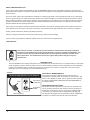
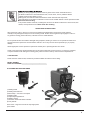
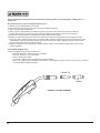
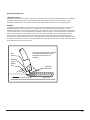
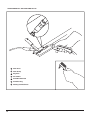
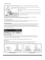
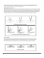
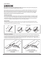
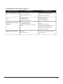
41185
90 Amp Flux Wire Welder
Instruction Manual
Need help with your new arc welder?
Call our customer service hotline at 1-800-386-0191
SAVE THESE INSTRUCTIONS
s
SAFETY BEGINS WITH YOU
It is the owner and/or operator’s responsibility to study all WARNINGS, operating, and maintenance instructions contained on the
product label and instruction manual prior to operation of this flux wire welder. The owner/operator shall retain product instructions for
future reference.
The owner and/or operator are responsible for maintenance, maintaining all decals or warning labels and while in use, maintaining
the unit in good working order. If the owner and/or operator are not fluent in English, the product warnings and instructions shall be
read and discussed with the operator in the operator’s native language by the purchaser/owner or his designee. Make sure that the
operator comprehends its contents. Safety information shall be emphasized and understood prior to usage. The flux wire welder
shall be inspected per the operating instructions.
Users of this flux wire welder must fully understand these instructions. Each person operating this flux wire welder must also be of
sound mind and body and must not be under the influence of any substance that might impair their vision, dexterity, or judgment.
Protect yourself and others by observing all safety information.
Explosion
Electric
Flying
Rays
Failure to comply with instructions could
result in personal injury
and/or property damage!
Shock
Sparks
PROP
Burns
65
If you encounter any problems or difficulties, please contact our customer service department at:
1-800-386-0191
Burns
Prop. 65
MANUAL
Fire
MANUAL
This instruction manual is intended for your benefit. Please read and follow the safety, installation,
maintenance and troubleshooting steps described within to ensure your safety and satisfaction. The
contents of this instruction manual are based upon the latest product information available at the
time of publication. The manufacturer reserves the right to make product changes at any time
without notice.
Fumes
EMF
Hearing
Read
INPUT
Read
OUTPUT
Heat &
INTRODUCTION
Your new VAPER flux wireSparks
welder
is
designed
for
use
on
standard 120V household current. It is equipped with a two step output
70 AMPS @ 23V
ng
power (amperage)
control to select the proper current for various welding conditions. Internal components are thermostatically
120V
10% DUTY CYCLE
protected.
This
VAPER
welder can weld steel ranging from 14 gauge up to 1/8” thick in a single pass. The unit is setup for
1~ 60 Hz
0.030” (0.8 mm) flux core welding wire when it leaves the factory.
ELECTRICAL REQUIREMENTS
120 Volt 20 Amp Dedicated Circuit Required
Plug
Grounded
Outlet Box
This equipment requires a dedicated 120 volt 20 amp circuit
equipped with a similarly rated circuit breaker or slow blow fuse. DO
NOT run other appliances, lights, tools or equipment while operating
this welder. EXTENSION CORDS ARE NOT RECOMMENDED for
use with this welder.
GROUNDING INSTRUCTIONS:
Grounded
Outlet
Grounding Plug
2
This product should be grounded. In the event of an electrical short
circuit, grounding reduces the risk of electric shock by providing an
escape wire for the electric current. This product is equipped with a
cord having a grounding wire with an appropriate grounding plug.
The plug must be plugged into an outlet that is properly installed and
grounded in accordance with all local codes and ordinances.
P
Improper installation of the grounding plug can result in a risk of electric shock. If repair or replacement of
the cord is necessary, do not connect the grounding wire to either flat blade terminal. The wire with insulation
having an outer surface that is green with or without yellow stripes is the grounding wire. This product is for use
on a nominal 120-volt circuit and has a three-prong grounding plug that looks like the plug illustrated. Make sure that the product is connected to
an outlet having the same configuration as the plug. No adapter could be used with this product. The third prong is to be used to ground the welder
and provide protection against electrical shock. Never remove the third prong. Check with a qualified electrician or serviceman if the grounding
instructions are not completely understood, or if in doubt as to whether the product is properly grounded. Do not modify the plug provided; if it will
not fit the outlet, have the proper outlet installed by a qualified electrician.
PROP
65
SAFETY ALERT
Electric
Shock
65 all safety messages that follow
Burns
This isFlying
the safety alert symbol. It Rays
is used to alert you to potential
personal injury Prop.
hazards. Obey
this symbol
to
avoid
possible
injury
or
death.
Sparks
Read and understand this entire instruction manual before attempting to assemble, install, operate or maintain
this arc welder. Failure to comply with the instructions may result in serious personal injury and/or property
damage!
The following signal words are used to emphasize safety warnings that must be followed when using this arc welder:
MANUAL
Indicates an imminently PROP
hazardous situation that, if not avoided, WILL result in death or serious
Fumes
OUTPUT
Flying
z
Sparks
65
EMFinjury.
Hearing
Explosion
Burns
ElectricProp. 65
Flying PROP
Rays
IndicatesShock
a potentially hazardous situationSparks
that, if not avoided, MAY result in minor or moderate
70 AMPS @ 23V
Rays
10% DUTY CYCLE
65
65
Electric
Shock Grounded
Flying
Prop.damage
65 to equipment.
Rays
Indicates important
information, which Burns
if not followed, MAY cause
Sparks
Outlet Box PROP
ug
Rays
Burns
Read
Grounded
Outlet
Hearing
Prop. 65
Burns
. 65
MANUAL
65
Flying
Sparks
EMF
OP
Fumes
Fire
Prop. 65
Heat &
Sparks
MANUAL
Fumes
Hearing
EMF
Read
MANUAL
OUTPUT
EMF
z
INPUT
70
AMPS @Hearing
23V
MANUAL
10% DUTY CYCLE
Read
Heat &
Sparks
ug
EMF
Heat &
Sparks
Hearing
R
OUTPUT
Read
120V
Heat &
1~ 60 Hz
p Dedicated Circuit Required
ng Plug
Bu
PROP
mp Dedicated Circuit Required
ng Plug
Heat &
Sparks
Indicates a potentially hazardous situation that, if not avoided, COULD result in death or serious
injury.
injury.
5
Read
Heat &
Sparks
70 AMPS @ 23V
10% DUTY CYCLE
Sparks
Grounded
Outlet Box
120 Volt 20 Amp Dedicated Circuit Required
Grounded
Outlet
Plug
Grounded
Outlet Box
3
IMPORTANT SAFETY RULES - FOR ARC WELDERS
SAVE THESE INSTRUCTIONS
ARC Welding can be hazardous. Protect yourself and others from possible serious injury or death. Keep children away. Pacemaker
wearers should consult with their doctor before operating.
Read and understand all instructions. Failure to follow all instructions included with this product could result in serious personal injury
PROP
and/or property damage.
65
For additional safety information, it is strongly recommended that you consult the following safety publications:
Flying
Sparks
Rays
Burns
Prop. 65
Recommended Safe Practices for the Preparation for Welding and Cutting of Containers and Piping, American Welding Society Standard AWS
F4.1, from American Welding Society, 550 N.W. LeJeune Rd, Miami, FL 33126 (phone: 305-443-9353 or 800-443-9353, website:
http://www.aws.org).
National Electrical Code, NFPA Standard 70, from National Fire Protection Association, P.O. Box 9101, 1 Battery March Park, Quincy, MA 022699101 (phone: 617-770-3000, website: www.nfpa.org and www.sparky.org).
Practice For Occupational And Educational Eye And Face Protection, ANSI Standard Z87.1, from American National Standards Institute, 11 West
42nd Street, New York, NY 10036-8002 (phone:
212-642-4900, website: http://www.ansi.org).
MANUAL
EMF
Standard for Fire Prevention During Welding, Cutting, and Other Hot Work, NFPA Standard 51B, from National Fire Protection Association, P.O. Box
9101, 1 Battery March Park, Quincy, MA 02269-9101 (phone: 617-770-3000, website: www.nfpa.org and www.sparky.org ).
Hearing
Read
Heat &
OSHA, Occupational Safety and Health Standards for General Industry, Title 29, Code of Federal Regulations (CFR), Part 1910, Subpart Q, and
Sparks
Part 1926, Subpart J, from U.S. Government Printing Office, Superintendent of Documents, P.O. Box 371954, Pittsburgh, PA 15250 (there are 10
Regional Offices--phone for Region 5, Chicago, is 312-353-2220, website: http://www.osha.gov).
Follow all local electrical and safety codes as well as in the United States, the National Electrical Codes (NEC) and the Occupational
Safety and Health Act (OSHA).
All installation operation, maintenance and repair procedures must be performed only by by qualified individuals.
The following hazards can occur during the normal use of this product:
ELECTRIC SHOCK CAN KILL!
Reduce the risk of death or serious injury from shock. Read, understand and follow ALL safety instructions. Be sure that
PROP
everyone who uses this welding equipment or who is a bystander in the welding area
understands and follows ALL safety
PROP
instructions as well.
65
65
sion
Flying
Sparks
e
Safety in Welding, Cutting, and Allied Processes, ANSI Standard Z49.1, from American Welding Society, 550 N.W. LeJeune Rd, Miami FL 33126
(phone: 305-443-9353 or 800-443-9353, website: http://www.aws.org)
• Do not touch live electrical parts. The electrode and work piece clamp are electrically “hot” when the welder is on.
Electric
Flying
Prop. 65
Rays
Burns
65
Shock
Sparks
• Insulate yourself from work and ground using dry insulating mats or covers big enough to prevent physical contact with the work piece or ground.
• Wear dry, Rays
hole-free insulating gloves
and body protection.Prop.
Burns
• Do not use in damp areas, if movement is confined, or if there is a danger of falling.
• Disconnect input power before installing or servicing this equipment.
• Properly install and ground this equipment according to its Owner’s manual and national, state, and local codes.
• Always verify the supply ground – check and be sure that input power cord ground wire is properly connected to ground terminal in
disconnect box or that cord plug is connected to a properly grounded receptacle outlet.
MANUAL
• Frequently inspect input power cord MANUAL
for damage or bare wiring – replace cord immediately if damaged – bare wiring can kill. Do not
use worn, damaged, undersized, or poorly spliced cables.
• Turn off all equipment when not in use.
EMF
0V
60 Hz
Fumes
Hearing
OUTPUT
4
70 AMPS @ 23V
10% DUTY CYCLE
EMF
Read
Hearing
Heat &
Sparks
Read
Heat &
Sparks
PROP
65
osion
• Do not drape cables over your body.
• If earth grounding of the workpiece is required, ground it directly with a separate cable.
• Do not allow any part of the body to touch the electrode if you are in contact with the ground or grounded work piece.
Electric
Flying Repair or replaceRays
Prop.
65
Burns
• Use
only well-maintained equipment.
damaged parts at once.
Maintain unit according
to manual.
• Always
keep all panels andSparks
covers securely in place when operating the welder.
Shock
• Clamp work cable with good metal-to-metal contact to workpiece or worktable as near the weld as practical.
• Insulate work clamp when not connected to workpiece to prevent contact with any metal object.
FUMES AND GASES can be hazardous!
Welding produces fumes and gases that are hazardous to your health.
MANUAL
• Keep
your head out of the fumes.
Do not breathe the
fumes.
EMF
Hearing
Read
Heat &
Fumes
• If inside, ventilate the area and/or use exhaust at the arc to remove welding fumes and gases.
Sparks
• If ventilation is poor, use an approved air-supplied respirator.
•
Read
the
Material
Safety
Data
Sheets
(MSDSs)
and
the
manufacturer’s
instructions
for
metals,
consumables,
coatings, cleaners, and
T
OUTPUT
degreasers.
70 AMPS
@ ned
23Vspace only if it is well ventilated, or while wearing an air-supplied respirator. Always have a trained watchperson
• Work
in a confi
120V
nearby.
Welding
fumes and gases can displace air and lower the oxygen level causing injury or death. Be sure the breathing air is safe.
10% DUTY
CYCLE
1~ 60 Hz
• Do not weld in locations near degreasing cleaning, or spraying operations. The heat and rays of the arc can react with vapors to form
highly toxic and irritating gases.
• Do not weld on coated metals, such as galvanized, lead, or cadmium plated steel, unless the coating is removed from the weld area, the
area is well ventilated, and if necessary, while wearing an air-supplied respirator. The coatings and any metals containing these elements
can Circuit
give off Required
toxic fumes if welded.
olt 20 Amp Dedicated
ire
Plug
PROP
65
Grounded
PROP
Outlet Box
ARC RAYS can burn eyes!
Never look at arc welding without proper eye protection. Arc rays from the welding process produce intense visible and
invisible (ultraviolet and infrared) rays that can burn eyes and skin. Hot sparks fly off from the weld and can burn eyes
Grounded
and skin.
Outlet
65
• Wear
a welding helmet fitted
with a proper shade of
filter to protect
Prop.
65 your face and eyes when welding or watching (see ANSI Z49.1 and
ying
Rays
Burns
Grounding Plug
Prop.
s
Z87.165
listed in Safety Standards).
arks
• Wear approved safety glasses with side shields under your helmet.
EMF
d
• Use protective screens or barriers to protect others from flash and glare; warn others in the area not to watch the arc.
• Wear protective clothing made from durable, flame resistant materials, leather welding gloves and full foot protection.
WELDING can cause fire or explosion!
Welding on closed containers, such as tanks, drums, or pipes, can cause them to explode. Sparks can fly off from the
welding arc. The flying sparks, hot workpiece, and hot equipment can cause fires and burns. Accidental contact of
electrode toMANUAL
metal objects can cause sparks, explosion, overheating, or fire. Check and be sure the area is safe before
doing any welding.
• Always
keep a fire extinguisher
readily available and watch
for fire.&
Hearing
Read
Heat
Heat
&
• Protect yourself and others from flying sparks and hot metal.
Sparks
• DoSparks
not weld where flying sparks can strike flammable material.
• Remove all flammable materials from the welding area. If this is not possible, tightly cover them with approved covers.
• Be alert that welding sparks and hot materials from welding can easily go through small cracks and openings to adjacent areas.
• Be aware that welding on a ceiling, floor, bulkhead, or partition can cause fire on the hidden side.
• Do not weld on closed containers such as tanks, drums, or pipes; unless they are properly prepared according to AWS F4.1 standards
• Connect work cable to the work as close to the welding area as practical to prevent welding current from traveling long, possibly unknown
paths and causing electric shock and fire hazards.
• Never use arc welder to thaw frozen pipes.
• Remove electrode from holder when not in use.
• Wear oil-free protective garments such as leather gloves, heavy shirt, cuff-less trousers, high shoes, and a cap.
• Remove any combustibles, such as butane lighters or matches, from your person before doing any welding.
5
PROP
FLYING METAL can injure eyes!
65
65
• Welding, chipping, wire brushing, and grinding cause sparks and flying metal. As welds cool, they can throw off slag.
• Wear ANSI approved safety glasses with side shields under your welding helmet.
PROP
tric
ck
Flying
Sparks
tric
ck
Flying
Sparks
ys
Burns
Rays can cause severe
Burnsburns!
HOT PARTS
Prop. 65
PROP
• Never
touch hot parts bare handed.
• Allow adequate cooling period before touching work piece.
65
Burns
Prop. 65
PROP
Rays
Prop. 65
65
MAGNETIC FIELDS can affectMANUAL
pacemakers!
mes
ng
rks
mes
Electromagnetic fields (EMF) are generated around electric welding cables and welding machines. These EMF’s can
interfere with some pacemakers. Pacemaker wearers should consult their doctor before going near arc welding, gouging,
or spot welding operations. To reduce magnetic fields in the workplace, use the following procedures:
EMF
Rays
Hearing
Read
• KeepBurns
cables close together by
twisting65
or taping them.
Prop.
MANUAL
ing
PS @ 23V
UTY CYCLE
EMF
Read
Explosion
65
Heat &
NOISE
can
damage hearing!
Sparks
Electric
Flying
Rays
Noise from some processes or equipment can damage hearing.
• WearShock
approved
ear protection Sparks
if noise level is high.
MANUAL
uit Required
Grounded
MF
Outlet Box Hearing
uit Required
Read
Burns
Heat &
• Do not install or place unit on, over, or near combustible surfaces.
• Do not install unit near flammables.
MANUAL
• Do not overload building wiring - be sure power supply system is properly sized, rated,
and protected to handle this unit.
OVERUSE
can cause OVERHEATING
EMF
Fumes
Fire
Hearing
• Allow cooling period; follow rated duty cycle.
• Reduce current or reduce duty cycle before starting to weld again.
• Do not block or filter airflow to unit.
INPUT
Read
OUTPUT
120V
1~ 60 Hz
70 AMPS @ 23V
10% DUTY CYCLE
MOVING PARTS can cause injury.
• Keep away from moving parts.
• Keep away from wire feed drive rollers.
• Keep all doors, panels, covers, and guards closed and secured in place.
120 Volt 20 Amp Dedicated Circuit Required
Plug
Grounded
Outlet
WELDING WIRE
canBox
cause injury.
• Do not point gun toward any part of the body, other people, or any metal when
threading welding
wire.
Grounded
• Do not press gunOutlet
trigger unnecessarily. When feeding welding wire through the gun,
the gun is electrically “live” and can cause electric shock.
Grounding Plug
6
Prop. 65
FIRE OR EXPLOSION hazard.
Sparks
Grounded
Outlet Box
Grounded
Outlet
PROP
• Arrange electrode and work piece cables to one side and away from the operator.
• Do not coil or drape cables around your body.
Hearing
Read
Heat &
• Keep welding power source and cables as far away from operator as practical.
Sparks
• Connect work clamp to workpiece as close to the weld as possible.
MANUAL
PS @ 23V
UTY CYCLE
Heat &
Sparks
Heat &
Sparks
ns
California Proposition 65 Warnings
• Welding or cutting equipment produces fumes or gases which contain chemicals known to
the State of California to cause birth defects and, in some cases, cancer. (California Health
& Safety Code Section 25249.5 et seq.)
• Battery posts, terminals and related accessories contain lead and lead compounds,
chemicals known to the State of California to cause cancer and birth defects or other reproductive harm.
Wash hands after handling.
• This product contains chemicals, including lead, known to the State of California to cause cancer, birth
defects, and reproductive harm. Wash hands after handling.
PROP
65
Prop. 65
UNPACKING & INSPECTION
After opening the carton, unpack your new flux wire welder and related parts & accessories. Please inspect it
carefully for any damage that may have occurred during transit. Please check it against the photograph on carton. If
any parts are missing, please call factory customer service at 1-800-386-0191.
AL
ad
Do not operate this flux wire welder if damaged during shipment, handling or misuse. Do not operate the welder until
the partsHeat
have been
& replaced or the fault rectified. Failure to do so may result in serious personal injury or property
damage.Sparks
All damaged parts must be repaired or replaced as needed prior to operating this flux wire welder.
Check to see that all nuts, bolts and fittings are secure before putting this tool into service. If you have any questions,
or require assistance with damaged or missing parts, please contact our factory customer service department at:
1-800-386-0191
Please have the model number, and date of purchase available for reference when calling.
MODEL NUMBER: _____________________________________
DATE OF PURCHASE: __________________________________
FLUX WIRE WELDER FEATURES
1
2
1) Welding shield
2) Welding hammer/brush
) Earth clamp – Connect to work piece
) Welding cable
) Output Amperage Selector
) ON/OFF Switch
) Automatic Thermal Shutdown Indicator
) Carry Handle
Power Cord – Plugs into 120 volt 20 amp single-phase
power outlets
7
SPECIFICATIONS:
Type:
Input Voltage:
Rated Output:
Output Power Settings:
Output Current:
Maximum Output Voltage:
Power Switch:
Power Cord:
Ground Cable & Clamp:
Ground Cable Connection:
Welding Cable:
Welding Wire:
90 Amp gasless flux-core wire welder
120 Volt (1~60Hz)
90 Amps @ 10% Duty Cycle
Switchable high/low adjustment
63.6 Amps - Low power output setting / 20% Duty cycle
90 Amps - High power output setting / 10% Duty cycle
32VAC
Illuminated On/Off Switch
6 Ft 15 Amp Power Plug
4.9 Ft Ground Cable with Clamp
Fixed Connection
6 Ft Wire feed welding cable
Uses flux-core welding wire 0.030” (0.8mm) or 0.035” (0.9mm) in diameter
INSTALLATION
Selecting the proper location can significantly increase the performance, reliability and life of the flux wire
welder.
For best results locate the welder in an environment that is clean and dry. Dust and dirt can accumulate in the welder and
retain moisture increasing wear for moving parts. Place the welder to ensure free circulation of air around all sides of the
welder.
The receptacle used for the welder must be properly grounded and the welder must be the only load on the power supply
circuit. Refer to the Electrical Requirements section at the beginning of this manual for correct circuit capacity.
Turn welder OFF before plugging into appropriate 120 volt 20 amp power outlet. The use of an extension cord is not
recommended for electric arc welding machines. Extension cord use will significantly degrade the performance of the welder.
ASSEMBLY
HAND SHIELD
1) Locate and insert filter lens securely into hand shield as shown.
2) To attach handle, place shield on flat surface and press handle into place.
NOTE: If you have never welded before or, have little experience, a full face welding
helmet is recommended. Both hands are needed to control the torch and adjust the
wire speed.
HANDLE INSTALLATION
1) Place handle on top of welder in alignment with two mounting holes in top cover.
2) Insert screws provided through handle ends and fasten securely into top cover.
FLUX CORE WIRE INSTALLTION
NOTE: Before installing welding wire, be sure that wire matches contact tip size located in end of torch. A mismatch
in size can cause the welding wire to slip or bind.
Always maintain control of loose end of welding wire to prevent unspooling.
Multi-Pass Welds
8
1) Verify that welder is turned OFF and is disconnected from the power source.
2) Unlock top cover panel and lift cover back to expose wire feed mechanism.
3) Push and rotate spool lock 1/4 turn counter-clockwise direction and pull to remove knob, spring and spool spacer.
4) Loosen wire feed tensioning screw on drive mechanism, lift tensioning spring arm up and hinge back the arm to allow
easier installation of wire.
5) Install flux core welding wire spool onto spindle so that wire unwinds from spool on the end closest to the tubular wire
feed guide.
6) Install spool spacer, spring and spool lock. Secure by pushing in spool lock and rotating knob 1/4 turn clockwise.
7) Hold wire spool so that it will not unravel and cut the wire end from the spool. Be sure the free end of the wire is straight
and without burrs.
8) Feed wire through tubular wire feed guide, over the groove in the drive roller and into the gun liner.
NOTE: The feed roller has two grooves, one for 0.6mm (0.240”) diameter wire
and one for 0.8mm (0.035”) diameter wire. Be sure that the correct groove size is
Burning of core materials inside the
correctly
Gasmatched to the
wire welding
electrode provideswire
a gas to being used. To reverse the roller, unscrew the
Nozzle
shield the molten metal as it
two screws securing the
roller supporting bracket and remove the bracket. The roller
solidifies.
Shielding
Gases
can now
be lifted off the drive shaft and reversed.
Reinstall the roller supporting
.030"/.035"
.024"
Molten
(0.8mm)
(0.6mm)
bracketSlag
and secure with the twoSolid
screws.
Wire
s inside the
a gas to
as it
.030"/.035"
(0.8mm)
Groove
Wire
rode
.024"
(0.6mm)
Groove
Groove
Electrode
Groove
d
Solidified Slag Weld
ce
Direction of travel
Work Piece
9) Pivot tensioning spring arm into the closed position so that pressure roller presses
welding wire into groove on
drive roller and secure free end of spring arm onto pointed end of tensioning screw.
Tighten wire feed tensioning
screw. NO NOT over tighten. A few full turns should be enough.
10) Remove nozzle from end of torch by twisting and pulling to expose contact tip.
Unscrew contact tip from end of
torch to remove.
11) Plug welder into a proper receptacle and turn welder ON.
12) Set wire speed to high. Activate gun trigger until wire feeds out past the end of
the torch. Turn the welder OFF.
13) Slip the contact tip over the welding wire protruding from the end of the torch
and screw tip into torch end. Install nozzle onto the end of the torch and trim end
of welding
wire so that about
1/4”Wire
is Length
extending from the end of the nozzle.
Wire Electrode
1/4"
To Work Piece
14) Close the top cover on the welder and secure with the latch.
Wire Electrode
1/4"
Wire Length
To Work Piece
Work Piece
Work Piece
STICKOUT
0-15˚
0-15˚
45˚
90˚
0-15˚
0-15˚
45˚
90˚
45˚
DUTY CYCLE
Welder duty cycle is the percentage of actual weld time that can occur in a ten minute interval. For example, at a 20%
duty cycle, actual welding45˚
can occur for two minutes,
and then the welder must Side
cool
for eight minutes.
End View of Nozzle Work Angle
View of Nozzle Work Angle
End View of Nozzle Work Angle
THERMOSTATIC PROTECTION
GROOVE WELD ANGLES
Internal components of this
welder
are
protected
from overheating
with
automatic thermal switch. A yellow lamp is
End View
of Nozzle
Work
Angle
Side View of Nozzle
Workan
Angle
illuminated on the front panel if the duty cycle is exceeded. Welding operations may continue when the yellow lamp is
no longer illuminated.
FILLET WELD ANGLES
Side View of Nozzle Work Angle
ANGLES
FILLET WELD ANGLES
Short
Normal
Long
ELECTRODE EXTENSION (STICKOUT)
Normal
ODE EXTENSION (STICKOUT)
Long
Side View
9
65
ays
Prop. 65
Burns
OPERATION
Be sure to read, understand and comply with all precautions in the Important Safety Rules section.
Be sure to read the entire section entitled Welding Guidelines prior to using this equipment.
Wire Length
1/4"
MANUAL
To Work Piece
ctrode
ce
1) Turn welder OFF and unplug from power source during preparation for welding.
ring
Read
Heat &
Sparks
2) Verify that the surfaces of metals to be joined are free from dirt, rust, paint, oil, scale or other contaminants. These
contaminants make welding difficult and
cause poor welds.
0-15˚
45˚
PROP
65
45˚
All persons operating this equipment or in the area while equipment is in use must wear protective welding
gear including: eye protection with proper shade, flame resistant clothing, leather welding gloves, and full
foot protection.
losion
Electric
Shock
End View of Nozzle Work Angle
Work
Angle
PROP
Flying Side View of NozzleRays
Sparks
FILLET WELD ANGLES
Flying
Sparks
Rays
Fire
65
Prop. 65
If heating,Burns
welding, or cuttingProp.
materials
65that are galvanized, zinc plated, lead, or cadmium
plated refer to the Important Safety Rules Section for instructions. Extremely toxic fumes are
created when these metals are PROP
heated.
Fumes
Flying
Burns
Rays
65
EMF
MANUAL
Hearing
Burns
3) Connect the work clamp to the work
MANUAL piece.
Read
Heat &
Sparks
Prop. 65
Long
UT SparksOUTPUT
Make sure the contact is on bare metal and
not70
obstructed
paint,
AMPS @by
23V
varnish,
corrosion,
or non-metallic materials.
10% Hearing
DUTY
CYCLE
Read
120V
EMF
T)
1~ 60
Hz
Heat &
Sparks
4) Set the amperage adjustment selector to
Volt 20 Amp Dedicated
Circuitsetting.
Required
MANUAL
the desired
Refer to the chart
below
for proper output current
Grounded
settings.
Plug
EMF
Outlet Box
Hearing
Long
Read
Gun Cable
Heat &
Sparks
Grounded
Outlet
STICKOUT)
Grounding Plug
Arc
Work Piece
Work Clamp
Fast
10
FCAW WELDING SETUP
Contact Tip
Nozzle
Metal
Thickness
Output Current
Settings (Amps)
18 - 14 Gauge
LOW (64A)
Thicker than 14 Gauge
HIGH (90A)
NOTE: Above settings are intended to serve as a general guideline only. Heat settings may vary according to welding
conditions and materials being welded.
Grounding against any metallic surface may produce an arc which could cause sparks and damage eyesight.
5) Set wire speed by rotating wire speed control knob to the middle position. NOTE: Switching the output current from
PROPthe corresponding wire speed. The wire feed speed
one setting to the other automatically increases and decreases
setting control provides fine tuning as needed after test welding.
65
6) Plug power cord into a proper power outlet as specified in the ELECTRICAL REQUIREMENTS section of this
instruction manual.
Flying
Sparks
Rays
7) Switch welder
power switch toBurns
the ON position.
Prop. 65
8) Ensure welding wire is protruding 1/4” from the end of the contact tip. If not, squeeze trigger to feed additional wire,
release trigger and cut wire to correct 1/4” length.
9) Position welding torch (gun) near work piece and raise hand shield to protect your eyes. Squeeze gun trigger to
activate welder. Adjust heat setting and wire speed as needed.
10) While welding, keep welding torch
travel at a constant speed and maintain an electrode length (protruding
MANUAL
welding wire) of 1/4” Follow the correct direction of travel for the joint type and orientation detailed in the WELDING
GUIDELINES section of this manual.
EMF
Hearing
Read
11) To stop welding, release gun trigger.
Heat &
Sparks
12) When finished welding, turn welder off and store properly.
MAINTENANCE
Disconnect power supply and turn machine off before inspecting or servicing any components. Keep wire
compartment cover closed when unit is in use. Open only when wire needs to be changed.
Before every use:
PROP
1) Check condition of welding cables and immediately repair or replace any cables with damaged insulation.
2) Check condition of power cord and immediately repair or replace any cord if damaged.
3) Check condition of welding torch tip and nozzle. Clean to remove any accumulated slag to avoid bridging between
the nozzle and contact tip. Bridging causes shortened nozzles, poor welds and overheating of the gun. Replace
welding torch tip or nozzle if damaged.
65
Flying
Sparks
Rays
Burns
Prop. 65
11
MANUAL
Gun Cabl
Do not operate this welding machine with cracked or missing insulation on welding cables, welding torch, or
power cord.
PROP
65
Flying
Sparks
Every three months, or more frequently with heavy use:
1) Replace any unreadable labels on the welder.
2) Use compressed air to blow all dust and dirt from the ventilation openings.
3) Vacuum dirt from wire compartment.
4) Clean grooves in wire feed drive roll. Remove wire from mechanism and remove two screws from drive roll
housing. Rays
Remove drive roll and
clean with a small brush.
Prop.Replace
65 damaged or worn drive roll as needed.
Burns
5) Inspect the incoming tubular wire feed guide and clean inside of tube if needed.
6) Clean the gun liner by removing the nozzle and contact tip. Clean the inside diameter of the welding torch with a
short piece of wire. Clean the cable liner by laying the cable out straight and blowing out the liner tube with clean, dry
compressed air. Flex the cable back and forth, and then blow the tube
out again. Repeat this process until the liner
Arc
tube is clean. Replace worn liner tube as needed.
7) Replace contact tip if hole is enlarged or irregularly shaped. (Refer to Consumable and Wear Parts section of this
manual for details).
Work Piece
MANUAL
EMF
Consumable and Wear Parts:
The following parts
require
periodic maintenance:
Work
Clamp
• Wire feed drive roller – Replace if worn or damaged
Hearing
Read
Heat &
• Gun
liner – Replace if worn
or damaged
• Nozzle – Replace as needed
Sparks
• Contact tips – Replace if hole is enlarged or irregularly shaped
• Wire – This welder accepts 4” diameter spools of flux cored welding wire. AWS E71T-GS or E71T-11 flux core wire is
recommended for welding mild steel.
Contact Tip
Nozzle
CONTACT TIP REPLACEMENT
12
WELDING GUIDELINES
LEARNING TO WELD
Welding is a skill that requires practice and, like any new skill, cannot be mastered without experience. The following
information is designed to help the inexperienced welder understand the basics of flux wire welding. It is not a
substitute for practice and is not intended to serve as the only information resource for the beginning welder.
GENERAL
This welding machine utilizes a process known as Flux Cored Arc Welding (FCAW). This process is used to bond
metals by heating them with an electric arc created between the wire electrode and the work piece. The wire
electrode used for flux cored arc welding has two parts. The outer wall of the wire electrode is similar in composition
to the base metal with an inner core filled with flux. While the metal is molten, it can be contaminated by elements in
the air. This contamination could weaken the weld. The flux creates a shielding gas when melted which forms a
protective barrier called slag that protects the molten metal from contaminants. When current (amperage) flows
through the circuit to the wire electrode, an arc is formed between the end of the electrode and the work piece. The
arc melts the wire and the work piece. The melted metal of the electrode wire flows into the molten crater and forms a
bond with the work piece as shown below.
Burning of core materials inside the
wire electrode provides a gas to
shield the molten metal as it
solidifies.
Gas
Nozzle
Shielding
Gases
Molten
Slag
Solid Wire
Electrode
.030"/.035"
(0.8mm)
Groove
Solidified Slag Weld
Direction of travel
Work Piece
13
SHIELDED METAL ARC WELDING SETUP
5
2
4
1
14
1
Work Piece
2
Work Clamp
3
Mig Torch
4
Gas Nozzle
5
Solid Wire Electrode
6
Solidified Slag
7
Welding Hammer/Brush
3
6
7
STRIKING AN ARC
1) Be sure the work clamp is properly attached to the work piece.
2) Position gun over joint to be welded. The end of the wire may lightly
touch the work piece.
Burning of core materials inside the
wire electrode provides a gas to
shield the molten metal as it
solidifies.
Gas
Nozzle
3) Position hand shield to protect face and eyes, squeeze trigger and begin
.030"/.035"
.024"
welding.
Shielding
Gases
Molten
Slag
(0.8mm)
Solid Wire
Electrode
5) To stop welding, release the trigger and pull the gun away from the work
piece after the arc goes out.
Solidified Slag Weld
Direction of travel
(0.6mm)
Groove
Groove
4) Hold gun
so that the contact tip is about
1/4” to 1/2” from the work piece.
Work Piece
NOTE: Should a ball form at the end of the wire after welding, feed out a short length of wire and trim the wire to
within about 1/4” from the nozzle and contact tip. This will allow for easier restrikes.
ARC WELDING BASICS
Five basic techniques
affect weld quality. These are: wire selection, amperage setting, weld angle, wire speed, and
Burning of core materials inside the
Gas
electrode
provides a techniques
gas to
travel
speed. Properwire
use
of these
is necessary for good weld quality.
Nozzle
shield the molten metal as it
solidifies.
Shielding
Gases
AMPERAGE
SETTING
.030"/.035"
.024"
TheMolten
correct amperage involvesSolid
the
adjustment of(0.8mm)
the welding machine to(0.6mm)
the required amp setting. This is regulated
Slag
Wire
Groove
by a switch on the welder. The Electrode
amperage requiredGroove
depends on the size (diameter)
of the wire used and the thickness
of the work piece. Consult below table. Excessive amps burn through light metals and the weld bead is flat and
Solidified Slag Weld
porous. The bead appears
high and irregular if the amperage is too low. NOTE: Practice on scrap material that is similar to
Direction of travel
Work Piece
the work piece to adjust settings.
Metal
Thickness
Output Current
Settings (Amps)
18 - 14 Gauge
LOW (64A)
Thicker than 14 Gauge
HIGH (90A)
1/4"
Wire Electrode
Wire Length
To Work Piece
Work Piece
WIRE TYPE AND SIZE
The correct type of wire involves a number of factors such as welding position, work piece material and thickness.
Flux cored wire is required for this unit and is0-15˚
commonly known by the AWS (American Welding Society) designation.
45˚
E-71T-GS or E71T-11 is recommended for this welder.
0-15˚
NOTE:90˚
Store wire in a clean,
90˚ dry location with low humidity to prolong the life of the wire.
Wire Electrode
WELD ANGLE
1/4"
Wire Length
45˚
To Work Piece
Weld angle is the angle at which the nozzle is held during
the welding process. Using the correct angle ensures
Work Piece
proper penetration and bead formation. Weld angle involves two positions - travel angle and work angle.
End View of Nozzle Work Angle
Side View of Nozzle Work Angle
End View of Nozzle Work Angle
0-15˚
90˚
0-15˚
45˚
GROOVE WELD ANGLES
Side View of Nozzle W
FILLET WELD ANGLES
90˚
45˚
End View of Nozzle Work Angle
Side View of Nozzle Work Angle
End View of Nozzle Work Angle
GROOVE WELD ANGLES
Short
Side View of Nozzle Work Angle
FILLET WELD ANGLES
Normal
ELECTRODE EXTENSION (STICKOUT)
Long
15
0-15˚
Wire Electrode
1/4"
0-15˚
45˚
Wire Length
To upon
Work Piece
Travel angle is the angle in the line of welding and may vary from 5º to 45º from the vertical, depending
welding
90˚ Work angle is the angle from horizontal,
conditions 90˚
and technique required.
measured
at
right
angles
to
the
line of
Work Piece
welding. For specific applications, consult an arc welding handbook.
45˚
WIRE SPEED AND STICKOUT
Wire speed is controlled by the knob on the control panel and is directly correlated to stickout. The speed needs to be matched
0-15˚
to the rateEnd
at which
the wire is being melted in the0-15˚
arc to maintain a stickout of approximateleyEnd
3/8”
to 1/2”. Setting
proper wire
View of Nozzle Work Angle
Side View of Nozzle Work Angle
View of Nozzle
Side View o
45˚Work Angle
speed should be performed on scrap material that is of the same type and thickness as the work piece. Set the speed too slow
and the wire will burn up into the contact tip with a sputtering sound. Set the speed too high and excessive spatter will result
from the wire
the 90˚
work piece before melting (a sputtering sound will also be heard under this condition). You will
90˚ pushing intoGROOVE
WELD ANGLES
FILLET WELD ANGLES
hear the sound of a proper arc - a steady, crisp sizzle, similar to bacon frying when the wire speed is set correctly.
45˚
End View of Nozzle Work Angle
Side View of Nozzle Work Angle
End View of Nozzle Work Angle
GROOVE WELD ANGLES
Short
Normal
Side View o
FILLET WELD ANGLES
Long
ELECTRODE EXTENSION (STICKOUT)
Short
Normal
Long
ELECTRODE EXTENSION (STICKOUT)
Short
Normal
Long
FILLET WELD ELECTRODE EXTENSIONS (STICKOUT)
TRAVEL SPEED
The travel speed is the rate at which the electrode is moved across the weld area. When the speed is too fast, the
bead is narrow and Short
bead ripples are pointed as shown. When the speed is to slow, the weld Long
metal piles up and the
Normal
bead is high and wide. To control travel speed, watch the width of the weld bead (not the arc) when welding. The
Fast bead width.
Slow molten metal behind the arc. Normal
weld bead is the orange,
Control travel speed to obtain a consistent
Work Clam
FILLET WELD ELECTRODE EXTENSIONS (STICKOUT)
GUN TRAVEL SPEED
Work Clam
10-45˚
Slow
90˚Normal
GUN TRAVEL SPEED
16
10-45˚
90˚
Fast
SLAG REMOVAL
Wear ANSI approved safety glasses (ANSI Standard Z87.1) and protective clothing when removing slag. Hot,
flying debris can cause personal injury to anyone in the area.
After completing the weld, wait for the welded sections PROP
to cool. A protective coating called slag now covers the weld
bead which prevents contaminants in the air from reacting with the molten metal. Once the weld cools to the point
that it is no longer glowing red, the slag can be removed. Removal is done with a chipping hammer. Lightly tap the
slag with the hammer and break it loose from the weld bead. The final clean-up is done with a wire brush. When
making multiple weld passes, remove the slag before each pass.
65
Flying
Sparks
Rays
WELDING POSITIONS
Burns
Prop. 65
Four basic welding positions can be used; flat, horizontal, vertical, and overhead. Welding in the flat position is easier
than any of the others because welding speed can he higher, the molten metal is less likely to run, better penetration
can be achieved, and the work is less fatiguing. Other positions require different techniques such as a weaving pass,
circular pass, and jogging. A higher skill level is required to complete these welds. All work should be performed in
the flat position if possible. For specific applications, consult an arc welding handbook.
WELD PASSES
EMF
Sometimes more then one pass is MANUAL
necessary to fill the joint. The root pass is first, followed by filler passes and the
cover pass as illustrated below. If the pieces are thick, it may be necessary to bevel the edges that are joined at a 60º
angle. Remember to remove the slag before each pass.
Hearing
Read
Heat &
Sparks
Multi-Pass Welds
PUSH VS PULL TECHNIQUE
The type and thickness of the work piece dictates which way to point the gun nozzle. For thin materials (18 gauge and up),
the nozzle should be pointed out in front of the weld puddle and push the puddle across the work piece. The push technique
is commonly used with Gas Shielded Arc Welding (MIG) which is better suited for welding thinner materials. For thicker
materials, the nozzle should point into the puddle to increase weld penetration. This is called the pull or drag technique and
is generally recommended when welding with flux cored wire.
PULL TECHNIQUE
PUSH TECHNIQUE
Commonly used for gas shielded arc
welding (MIG)
Commonly used for flux cored arc
welding (MIG)
17
TROUBLESHOOTING GUIDE - WELDER
Problem Encountered
Possible Cause
No power at receptacle.
No weld output; wire does not
feed; fan does not run.
Unit is unplugged.
Power switch is in the OFF position.
Defective power switch.
Broken or damaged power cable.
No weld output; wire does
not feed; fan continues to
run.
Welder gives trickle shocks.
Welder overheats - blows fuses,
trips circuit breaker.
No weld output; wire feeds
properly.
Low weld output.
No wire feed when gun
trigger is pulled.
Weld pops and sputters
18
Corrective Action
Check circuit fuse or circuit breaker.
Verify plug is properly inserted into power
outlet.
Confirm power switch is in the ON
position.
Replace switch.
Power cable requires service.
Duty cycle exceeded – Thermostat may
be tripped due to overheating.
Gun trigger may be faulty.
Amperage selector switch is between
power settings.
Let machine cool. Do not exceed duty
cycle. Remove any air obstruction to
the machine.
Disassemble torch handle and check
trigger switch connections, tighten or
reconnect as needed.Check amperage
selector switch for proper setting.
Accidental contact with work piece.
Current leakage caused by moist clothing
or work area.
Avoid contact with work piece.Make sure
clothing and work area are dry.
Use of extension cord.
Overloaded circuit.
If possible, relocate welder to avoid use of
extension cord. If relocation is not possible,
use thicker (lower gauge number) extension
cord.
Welder requires a dedicated 120V circuit.
Work piece not properly grounded.
Work contact tip.
Connect work clamp to work piece to get
good metal to metal contact.
Replace contact tip.
Inadequate or overloaded circuit.
Amperage selector switch is incorrectly
set.
Welder requires a dedicated 120V
circuit. If possible, relocate welder to avoid
use of extension cord. If relocation is not
possible, use thicker (lower gauge number)
extension cord.
Check amperage selector switch for
proper setting.
Gun cable kinked, damaged, or worn.
Drive roller tension improperly set.
Incorrect drive roller groove improperly
matched to wire size.
Wire spool hub tension too high.
Improper contact tip size.
Gun cable liner and/or wire inlet guide
tube clogged or dirty.
Worn drive roller and/or pressure bearing.
Wire speed setting is incorrect.
Contact tip is too large.
Drive roller slipping.
Straighten gun cable and/or replace
damaged parts.
Adjust drive roller pressure.
Change drive driver roller to proper groove.
Readjust hub tension.
Replace contact tip if blocked.
Clean or replace wire inlet guide tube or
liner if dirty or plugged.
Replace drive roller or pressure bearing
if worn or slipping.
Check and clear any restrictions at
drive assembly and liner.
Adjust wire speed to proper setting.
Replace with correct contact tip size.
Increase drive roller pressure.
TROUBLESHOOTING GUIDE - WELDS
Problem Encountered
Possible Cause
Corrective Action
Inconsistent travel speed.
Output amp setting incorrect.
Adjust and maintain travel speed.
Carefully watch and control the width of
the molten weld bead.
Ragged depressions at edge of
weld.
Travel speed too fast.
Wire speed too fast.
Output amp setting to high.
Decrease travel speed.
Decrease wire speed.
Reduce output amp setting.
Weld bead does not penetrate
work piece.
Inconsistent travel speed.
Ouput amp setting too low.
Extension cord is tool long or improperly
sized.
Decrease and maintain consistant travel
speed.
Increase output amp setting.
If possible, relocate welder to avoid use
of extension cord. If relocation is not
possible, use thicker (lower gauge
number) extension cord.
Electrodes sputter and stick.
Damp wire.
Wire speed too fast
Bead is intermittently too thin or
too thick.
Adjust output amp setting.
Use dry wire and store in a dry location.
Reduce wire speed.
19
ONE YEAR LIMITED WARRANTY - STAR ASIA-USA, LLC ELECTRIC ARC WELDERS
Star Asia-USA, LLC (hereinafter “seller”) warrants to the original purchaser only, that this product will be free from defects in
material or workmanship for a period of one year from date of purchase for home domestic use.
Warranty Performance
Warranty coverage is conditioned upon purchaser furnishing seller or its authorized service center with adequate written proof of
the original purchase date. Products returned, freight prepaid and insured, to our factory or to an Authorized Service Center will
be inspected and repaired or replaced, at seller’s option, free of charge if found to be defective and subject to warranty. Defective
parts not subject to normal wear and tear will be repaired or replaced, at our option during the above stated warranty periods. In
any event, reimbursement is limited to the purchase price paid. Other than the postage and insurance requirement, no charge
will be made for repairs or replacements covered by this warranty. Under no circumstances shall the manufacturer bear any
responsibility for loss of the unit, loss of time or rental, inconvenience, commercial loss or consequential damages. There are no
warranties which extend beyond the description of the face hereof.
Exclusions
This warranty does not cover parts damaged due to normal wear, abnormal conditions, misapplication, misuse, abuse, accidents,
operation at other than recommended pressures or temperatures, improper storage or freight damage. Parts damaged or worn by
operation in dusty environments are not warranted. Failure to follow recommended operating and maintenance procedures also
voids warranty.
Additional items not covered under this warranty: product failure caused by rain, excessive humidity, corrosive environments or
other contaminants; cosmetic defects that do not interfere with product’s functionality.
This warranty shall not apply when: the product has been used for commercial or rental purposes; defects in materials or
workmanship or damages result from repairs or alterations which have been made or attempted by others or the unauthorized
use of nonconforming parts; this damage is due to abuse, improper maintenance, neglect or accident; or the damage is due to
use of the product after partial failure or use with improper accessories. Warranty does not apply to accessory items such as
electrodes, welding wire, contact tips, gun liner, and nozzles.
Seller will not be liable for: labor charges, loss or damage resulting from improper operation, maintenance or repairs made by
persons other than a Star Asia-USA, LLC Authorized Service Center.
The use of other than genuine Star Asia-USA, LLC Repair Parts will void warranty.
Warranty Disclaimers
NO WARRANTY, ORAL OR WRITTEN, OTHER THAN THE ABOVE WARRANTY IS MADE WITH REGARD TO THIS
PRODUCT, ANY IMPLIED WARRANTIES OF SELLER REGARDING THIS PRODUCT INCLUDING BUT NOT LIMITED TO, THE
IMPLIED WARRANTIES OF MERCHANTABILITY OR FITNESS FOR A PARTICULAR PURPOSE, ARE EXCLUDED. BUYER’S
OR USER’S REMEDIES ARE SOLELY AND EXCLUSIVELY AS STATED ABOVE. STAR ASIA-USA, LLC SHALL IN NO
EVENT BE LIABLE FOR INCIDENTAL, CONSEQUENTIAL, INDIRECT, OR SPECIAL DAMAGES. IN NO EVENT, WHETHER
AS A RESULT OF A BREACH OF CONTRACT, WARRANTY, TORT (INCLUDING NEGLIGENCE) OR OTHERWISE, SHALL
SELLER’S LIABILITY EXCEED THE PRICE OF THE PRODUCT WHICH HAS GIVEN RISE TO THE CLAIM OR LIABILITY.
ANY LIABILITY CONNECTED WITH THE USE OF THIS PRODUCT SHALL TERMINATE UPON THE EXPIRATION OF THE
WARRANTY PERIODS SPECIFIED ABOVE.
Limitations on Warranty Disclaimers
Any implied warranties shall be limited in duration to one year from the date of purchase. In some states of the U.S.A. and in
some provinces of Canada there is no limitation for how long an implied warranty is valid, so the aforementioned limitation may
not apply to you.
In no event shall seller be liable for any incidental or consequential damages (including but not limited to liability for loss of profits)
arising from the sale or use of this product. In some states of the U.S.A. and in some provinces of Canada the exclusion or
limitation of incidental or consequential damages is not allowed, so the aforementioned limitation or exclusion may not apply to
you.
This limited warranty gives you specific legal rights, and you may also have other rights which vary from state to state in the
U.S.A., Canada and the Commonwealth of Puerto Rico. For warranty coverage within other countries, contact your local Star
Asia-USA, LLC dealer or importer.
20
Distributed by Star Asia-USA, LLC
P.O. Box 58399, Renton, WA 98058
Consumer Service: 800-386-0191
e-mail: [email protected]
©2005 Star Asia-USA, LLC
21