1
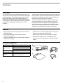
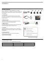
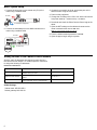
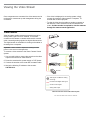
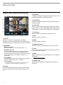
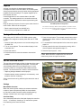
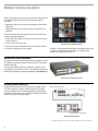
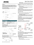
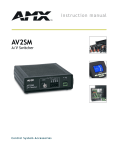
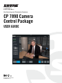
Conferencing and Discussion Systems CP 7890 Camera Control Package USER GUIDE © 2014 Shure Incorporated 27A26855 (Rev. 1) Table of Contents Table of Contents 2 Overview Description Features Included Accessories 3 3 3 3 Installation System Overview Downloading the App Basic System Setup Adding Devices to the Camera Control Network 4 4 4 5 5 Viewing the Video Stream Video Encoder 6 6 2 Using the App Camera Control Application Description Layouts Saving a Camera Preset Set the Overview Scene 7 7 8 8 8 Multiple Camera Operation Networked Video Switcher Analog Video Switchers 9 9 9 Addendum Operation with Additional Equipment Changing the Wireless Channel VISCA Cables configuration with Sony cameras Troubleshooting Trademarks 10 10 10 11 12 12 Overview Description The Shure Camera Control Package allows remote set up and control of a camera system for conferences, discussions or meeting spaces. The package integrates with the DCS 6000 or DDS 5900 system, using realtime conference information to provide accurate, automated camera display of the speaker or specific participants. A steady, consistent camera feed is available for live broadcast or archival recording. Features • Easily integrates a camera system with the DCS 6000 or DDS 5900 system • Allows automated view of the speaker once their microphone is turned on • Produces consistently accurate camera views suitable for broadcast or recording Included Accessories Component Description A camera setup application operates on an iPad® or Android™ tablet, providing a quick and simple method for programming the camera view. The app is used to save and recall room layouts of up to 400 seats for four cameras. The camera views are saved to the AMX controller, which contains preloaded Shure control software for plug-andplay operation. Once the camera views are programmed and saved from the app, the AMX unit operates the camera system without requiring the tablet. The CP 7890 system supports any cameras that operate the Visca protocol. • Operates with any camera supporting the Visca protocol • Programs and saves three room layouts • Stores camera views for up to 400 seats per camera • Stores camera views for up to 4 cameras per seat • Free camera control app operates on iPad and Android tablets AMX® NX-1200 ① System Controller NETLINX MASTER Camera control software (preloaded) LINK/ACT STATUS CONFIG OUTPUT Power Supply ② Wireless Router 3 2 3 4 INPUT TX 1 I/O 1 1 2 2 RX TX RX NX-1200 3 2 IRRX 4 IRRX ID CONFIG Linksys wireless E2500 Power Supply ③ Cables 1 IR SERIAL •Camera: VISCA to RS-232 Cable, 2 m •Network: RJ-45 to RJ-45, 2 m Lin ksys 0 20 E3 Installation System Overview The CP 7890 provides easy management of a camera system connected to a conference or discussion system. The following diagram describes the function of each component in the system. ① ① Control Unit* The control unit (CU) sends realtime microphone status information to the AMX unit so that camera views match the current speakers. ② ⑤ 00 sys E32 Link Verizon Layouts OPEN MICS 0 SEAT NUMBER 25 Select Seat 25 Test Preset Save Delete SPEED (1 - 20) CAMERA VIEWS 10 ③ NETLINX MASTER LINK/ACT STATUS ③ AMX Controller The AMX controller stores settings made from the app and operates the camera system during the event. CONFIG OUTPUT 1 2 3 4 INPUT IR SERIAL TX 1 I/O 1 2 RX TX RX 1 ④ NX-1200 2 3 2 IRRX 4 IRRX ID CONFIG ④ Cameras* Up to four cameras are controlled by the CP 7980 system when they are connected to the AMX unit with the VISCA to RS-232 cable. Wireless system control Standard IP network Visca camera commands ⑤ Tablet Application The app allows remote set up of the camera system. DCS-LAN conference equipment network Analog video output *Not included with the CP 7980 Shure Camera Control Package Downloading the App Download the Shure CP 7890 Camera App for your tablet: Device Where to Download Minimum Requirements Apple iPad App store iOS 7.0 Android Tablet Google Play™ Jelly Bean 4.1 4 Setup Connected ZOOM ② Wireless Router The router connects additional components and enables wireless connection to the camera system. 100% 9:43 PM Camera Controller NETWORK 1 2 3 4 Basic System Setup 1.Connect the TCP/IP port on the central unit (CU) to the router using a network cable. 4.Power on the equipment. TCP/IP to router 5.Change the IP settings of the CU to 192.168.10.110 from the front panel LAN Setup > IP Address Setup > IP Address. TCP/IP to conference equipment +12VDC RS - 232 / 422 / 485 2A MAX CLASS 2 RS - 232 AXLINK RS - 232 AXLINK RXD TXD L/A PWR 6.Download and install the Shure Camera Control app to the tablet. 7.Open the WiFi settings on the tablet and connect to the router's network name: Shure CP 7890-xxxA Note: xxx = unit's production number (001, 002, etc) 8.Enter the default network password: 123456789 9.Open the app to begin using the system. 12VDC NX-1200 + SPD PWR LAN 10 / 100 12VDC + PWR INPUT LAN 10 / 100 INPUT PWR to camera(s) GND RTS CTS TX- TX+ RX- RS - 232 * NX-1200 LAN 10 / 100 GND AXM AXP * * RTS CTS TXD RXD GND GND TXD RTS CTS 2A MAX MAX CLASS CLASS 2 2 COMBINED OUTLETS .5A L/A SPD RXD RX- TX- +12VDC +12VDC GND IR TX+ .5A MAX CLASS 2 COMBINED OUTLETS GND AXM AXP I/O * RS - 232 / 422 / 485 +12VDC RTS CTS TXD RXD GND GND TXD CTS RX- TX- RXD * * 2 1 + IR+ + LAN 10 / 100 to router 1 2 1 4 3I/O TX+ * 2 + RTS GND 2.Connect the LAN 10/100 port on the AMX controller to the router using a network cable. 4 3 2 1 3.Connect the camera(s) to the RS-232/422/485 port on the AMX controller using the Visca cable. RS - 232 /422 Adding Devices to the Camera Control Network Specific, static IP addresses are required for each device in the camera control network. For reliable operation, make sure to assign the following IP addresses: USB USB 1 1 2 Ethernet 3 4 Internet 12VDC Power 2 Ethernet 3 4 Internet 12VDC Power IP Address for Each Device Device Function IP Address Central Unit (CU) Triggers the camera system to display the speakers during the event. 192.168.10.110 Networked Video Switcher Control multiple cameras from a networked device. 192.168.10.111 Video Encoder View the camera signal through the camera control application, or from a networked PC 192.168.10.91 Global Settings: Subnet mask: 255.255.255.0 Default gateway:192.168.10.1 5 Viewing the Video Stream Once components are connected, the video stream can be monitored for camera set up and management during the conference. • If the video is displayed on an analog system, simply connect the camera's video output to a computer, TV, recorder with a video input jack. • To view the video from the tablet or another computer on the network, a video encoder must be connected to the router. A video encoder is required to view the cameras through the camera control application. Video Encoder Video encoders enable remote access and control of an analog video signal over an IP network. The encoder connects to the camera or camera switcher with a coaxial cable, converting analog signals into digital video streams. The digital stream is accessible for viewing on the tablet or recording from a computer. Verizon 100% 9:43 PM Camera Controller Layouts Setup NETWORK Connected OPEN MICS 0 0 sys E320 Link SEAT NUMBER 25 Select Seat 25 Test Preset Save Delete Important: a video encoder is required for viewing the video picture on the camera control application. To connect a video encoder to the Shure Camera Control system: 1.Use a coaxial cable to connect the encoder to the video output on the camera or video switcher. ZOOM SPEED (1 - 20) CAMERA VIEWS 10 1 2 3 4 NETLINX MASTER LINK/ACT STATUS CONFIG OUTPUT 1 2 3 4 INPUT IR SERIAL TX 1 I/O 1 1 2 2 RX TX NX-1200 3 2 IRRX RX 4 IRRX ID CONFIG 2.Power the encoder with a power supply or PoE injector. 3.Connect the encoder to the router with a network cable. EXTRON ISS 506 4.Assign the following IP address to the encoder: 192.168.10.91. Encoder Video signal over WiFi for viewing on the app IP network with digital video signal Camera control signals Analog video output Video Encoder with the CP 7980 Camera System The encoder adds video to the IP network 6 Using the App Camera Control Application Description ① Verizon 100% 9:43 PM Camera Controller ③ ④ ⑤ ⑥ ⑦ ⑧ ⑨ ⑩ ② Layouts Setup NETWORK Connected ⑤ Seat Number Displays the selected number for saving a camera setting or testing the preset. OPEN MICS 0 SEAT NUMBER 25 Select Seat 25 ⑥ Select Seat Scroll to the desired seat by pressing the up (+) and down (-) buttons. Seats 0 - 400 are selectable for DDS 5900 and DCS 6000 systems. The seat number displays in the above field. Test Preset Save Delete ZOOM ③ SPEED (1 - 20) CAMERA VIEWS 10 ⑪ ⑫ 1 2 3 4 ⑬ ① Layouts A layout is a collection of saved camera views that correspond to seats in the DDS 5900 or DCS 6000 system. Recall and save camera settings for up to three room layouts. ② Setup Menu Number of Cameras Select the number of cameras used in the system (1 - 4). Max NOM to Overview The camera system defaults to the overview scene when the maximum number of open microphones (NOM) has been reached. This setting avoids overly-confusing camera switching when multiple people are in a dialogue. Variable from 1 - 8 microphones. Overview Delay Set a short delay before the system displays the overview when the maximum NOM is reached (1 - 10 seconds). Camera Tracking •On: Cameras automatically move according to the saved layout •Off (bypass): Cameras do not follow any saved layouts ③ Network Connected illuminates green when the tablet is connected to the same network as the wireless router and AMX control unit. 7 ④ Open Mics Displays the number of microphones that are turned on in the connected DCS 6000 or DDS 5900 system. ⑦ Test Preset Select to view the saved camera view for that seat. ⑧ Save Saves the current camera view. ⑨ Delete Clears the preset for that seat. ⑩ Adjustment Arrows Press the arrows to move the camera to the desired view. ⑪ Zoom Control the coverage area of the view by pressing the zoom in (+) or zoom out (-) buttons. ⑫ Speed Adjust the speed of the camera movement from 1 (fastest) to 20 (slowest). Note: Does not save; for setup only. ⑬ Camera Views Select between cameras for setting up the view preset for each seat. Layouts A layout is a collection of saved camera views that correspond to seats in the DDS 5900 or DCS 6000 system. Saving layouts reduces set up time when sharing equipment between rooms and meetings. The system supports up to three layouts at a time. Use the application to save camera views to the AMX controller. The settings persist in the controller and do not require the tablet to operate the camera system during the event. Begin by opening a layout. Go to the Layouts menu from the main screen. Select one of the layouts: • Recall: open the layout from the AMX unit. • Save: save layout updates to the AMX unit. Saving a Camera Preset Save Multiple Room Arrangements The camera control app allows camera systems to operate in mixeduse rooms by saving seating positions for up to three different seating arrangements, or Layouts. When using the DCS 6000 or DDS 5900 systems, seats 0 - 400 can be assigned a camera preset with the CP 7890 system. 5.Press the save button. The selected camera button shows displays with a darker outline to show that the preset has been saved. 1.Select a layout and press Recall to load the settings from the AMX unit. 6.To set additional camera presets for the same seat, repeat steps 2-4. 2.Turn on a microphone. The seat number displays in the Seat Number field. 7.Set the preset for the rest of the seats by turning off the first microphone and repeat the steps 1-6. 3.Select the camera. 8.Save the layout (Layouts > Save). 4.Press the arrows to move the camera to the desired position. Set the Overview Scene The overview scene displays a field-of-view shot of the event that doesn't focus on a particular participant. The overview scene displays when the no microphones are on, or the maximum number of microphones (Max NOM) has been reached. The overview scene is useful in several scenarios: • Capturing dialogue between several people • Situations where camera switching is not necessary, such as before and after a meeting. Set the overview scene by positioning the camera for seat 0 or 400. Settings Max NOM to Overview When the camera system reaches the selected maximum number of open microphones (NOM), the view defaults to Overview to avoid excessive camera switching during dialogue. Variable from one to eight microphones. Overview Delay Set a short delay before the video feed displays the overview shot (1 – 10 seconds). A setting of "0" restricts the system from switching to the overview scene. 8 Tip: For quick configuration, use the keypad to type the seat number. When that seat is completed, the next seat can be selected using the left and right arrow buttons. Multiple Camera Operation When using more than one camera, connect a video switcher to manage multiple video feeds. There are two types of switchers: • Networked switchers: connect to the wireless router with a LAN cable • Analog switchers: use contact closures connected to the AMX unit Once the camera and video switchers are connected to the system, open the application. 1.Select the total number of cameras from the menu: Setup > Number of Cameras. Verizon Layouts 4.Position it and press the Save button. Setup NETWORK ② Connected OPEN MICS 0 SEAT NUMBER 25 ④ ① Select Seat 25 Test Preset Save Delete ZOOM SPEED (1 - 20) CAMERA VIEWS 1 10 2.Press Setup to exit the menu. 3.Select one of four numbered blocks to select the camera. 100% 9:43 PM Camera Controller 2 3 4 ③ Save Scenes for Multiple Cameras Camera 1 is the default camera when a microphone is turned on. When a second microphone turns on, Camera 2 will display for that speaker, and so on. Networked Video Switcher This type of switcher connects to the camera system over the IP network. The system operates with the Extron® Seamless Switcher ISS 506. Use a typical network cable to connect the switcher to the RJ-45 ports on the wireless router. The switcher must use the following IP address for system compatibility: 192.168.10.111 Extron Seamless Switcher ISS 506 2 + I/O +12VDC +12VDC GND RXD TXD CTS RTS IR TX+ * 1 * + RS - 232 / 422 / 485 .5A MAX CLASS 2 COMBINED OUTLETS 2A MAX CLASS 2 GND AXM AXP * 4 3 2 1 RTS CTS TXD RXD GND GND AMX controller control I/O RX- Analog video switchers connect directly to the AMX control unit with a multi-pin, contact closure to ground. The AMX routes commands from the tablet application to the analog switcher for initial setup, and controls the switcher during the event according to the saved layout. TX- Analog Video Switchers RS - 232 AXLINK MSW 4V rs POWER 12V .2A MAX L/A NX-1200 SPD PWR 12VDC + LAN 10 / 100 INPUT PWR RS-232 1 3 2 4 I N P U T S O U T A P U T S Tx Rx CONTACT B 1 2 3 4 Analog switcher contact inputs Example Analog Switcher Connect the switcher contact output to the I/O ports on the AMX unit. 9 Addendum Operation with Additional Equipment Additional components may operate with the camera control system. Go to Settings menu to select from the compatible component categories: • Camera protocol • Microphone system • Camera switcher Changing the Wireless Channel Change the wireless router channel if there is a problem with the tablet connection. 1.Connect a computer to the router using a wired or wireless connection. 2.Access the router interface by opening a browser. Type the following in the address line: http://192.168.10.1 and press enter. 3.Enter the site by typing in the default credentials: Login: (leave empty) Password: admin 4.Go to Basis Wireless Settings > Wireless and change the channel from Auto to any of the channels 36 – 40 – 44 – 48. 5.Save settings and reboot the router. 10 VISCA Control Cables configuration with Sony cameras Reference the following drawing for the VISCA cable configuration for both RS-422 and RS-232 for Sony cameras. RS-422 Connection Note: The pin layout shown for RS-422 is for Sony EVI-D70P cameras. For Sony BRC-300/300P cameras, Pin 1 and Pin 9 are swapped. For other cameras, please check the camera manual. RS-232 Connection 11 Troubleshooting The menus in the CP 7890 software are not active •Check the WiFi settings on the tablet. The Shure CP 7890-xxxA should be connected The camera view does not move when controlling from the Camera Operation or Camera Preset menu •Check that the Visca cable from the camera is connected to the RS232/422/485 port on the AMX unit •Check whether RS-232 or RS-422 is used and corresponding setting is used on the camera •Reboot the camera The seat no. does not display when turning microphones on •Check LAN connection between central unit (CU) and wireless router. The cable must be connected to the LAN port on central unit and NOT theDCS-LAN port •Check that the IP address of the CU is set to 192.168.10.110 No camera movement when turning microphones on •Check that a preset is made for the seat. Seat number must be in the range 0-400. •Check that the Camera is connected and working by loading a layout and pressing the test preset button for a seat. •Check that Camera Tracking is on (Setup menu in the app) Trademarks Android and Google Play are trademarks of Google Inc. Apple and iPad are trademarks of Apple Inc. AMX is a trademark of AMX, LLC Extron is a trademark of RGB Systems, Incorporated 12