1
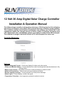
12 Volt 30 Amp Digital Solar Charge Controller
Installation & Operation Manual
This 30Amp charge controller is designed to protect your 12Volt Lead-acid or Gel-cell battery
from being overcharge by solar panel, which prevents discharge of battery during nighttime.
This controller reduces overall system maintenance and prolongs your battery life. It will
continuously display the charging current or battery voltage in charging proceeding from
LCD digital meter; also automatically indicate your battery condition from LED bar-graph.
This controller is design to work with all kinds of 12 Volt solar panels for indoor use.
Controller Dimension
Features
• Digital Voltage and Current – Continuous display for battery and solar panels
• Protect and Maintain battery – Protect batteries from solar overcharge and maintains batteries in fully
3charged state
• Battery Type selected – Selected the Gel-cell or Lead-acid battery by selector switch
• Safety circuit protection – Short circuit and reverse polarity protection
• Reverse leakage protection – Protect batteries from solar power discharge
• Status Lights – Colored Battery condition bar-graph
• Temperature Protection– Over temperature protection and auto-resume
• Terminal Block – for easy wire connections
• Mounting Options – Can mount any surface or onto a wall
Installation and Operation
WARNING: Follow all safety precautions of the battery manufacturer. Proper ventilation
must be provided for the batteries. Most batteries produce hydrogen gas when charging,
which is extremely explosive. Provide adequate battery ventilation.
DO NOT Expose the battery to open flame, matches, cigarettes or sparks.
CAUTION: DO NOT EXCEED THE UNIT’S VOLTAGE AND CURRENT RATINGS:
• Do not exceed the maximum solar array voltage rating of 26 volts.
• Do not exceed the maximum current rating of 30 amps.
CAUTION: DO NOT DEVIATE FROM THE RECOMMENDED WIRING INSTRUCTIONS:
• Do not reverse Battery (+) and Battery (-) connections to the controller.
• Do not reverse the Battery and Solar Array connections to the controller.
• Unplug the controller from the solar array and battery before attempting any maintenance
or cleaning.
• Do not disassemble the controller. Take it to a qualified service center when service or
repair is required. Incorrect reassembly may result in a risk of damage the unit.
• Installation should be made by a qualified person.
• Save these instructions for future reference.
PERSONAL PRECAUTION:
• If battery acid contacts skin or clothing, wash immediately with soap and water. If acid
enters eye, immediately flush eye with running cold water for at least 10 minutes and get
medical attention immediately.
• Never smoke or allow a spark or flame in vicinity of battery.
• Be extra cautious to reduce risk of dropping a metal tool onto battery. It might spark or
short-circuit battery or other electrical part that may cause explosion.
1. Mounting
1.1 Mounting Consideration: - The solar controller is designed to be flush mounting or wall
mounting.
1.2 Flush mounting: The flush mounted unit requires a rectangular cutout in the mounting
surface with sufficient space (2-3 inches) behind to accommodate the controller.
1.3 Wall mounting: The wall-mounted unit is installed onto a wall surface using two
mounting screws. Electrical connections are made to the back of the controller. Wiring can be
run down the wall or through a hole in the wall directly below the controller.
1.4 Recommended Battery Capacity : 12V 45AH minimum.
2. Connection Procedures (refer to Connection diagram)
2.1 Fix the mounting of the solar controller panel.
2.2 Select Lead-Acid or Gel-cell Battery modes.
2.3 Connect the solar panel positive side to the solar controller ARRAY POSITIVE + by a suitable wire
(Be careful not to short circuit the solar array.)
2.4 Connect the solar panel negative side to the solar controller ARRAY NEGATIVE– by a suitable wire
2.5 Connect the Lead-Acid or Gel-cell battery positive side to the solar controller BATTERY POSITIVE +
by a suitable wire.
2.6 Connect the Lead-Acid or Gel-cell battery negative side to the solar controller BATTERY
NEGATIVE – by a suitable wire.
Any wiring variation of size or length can affect the LCD meter performance
3. Wire size: - Refer to the “WIRE SIZE” chart below to determine the minimum size wire
needed for each connection. Note that the bigger the wire, the lower the AWG. When using
large stranded wire, you may need to divide the ends into two groups and straddle the screw
on the terminal block. (Based on maximum current)
Length of Wire
AWG
Battery Connection
Distance round trip (meter)
< 0.6m
6 or 8
Solar Array Connection
Distance round trip (meter)
6m
9m
12m
10
8
6
4. Wire type: - When possible, use stranded wire instead of solid wire. Stranded wire does
not fatigue and cause loose connections over time as easily as solid wire. Use red wire for (+)
and black for (–). Accept one wire at 6 AWG (stranded) or two wires at 8 AWG. Use crimp
connectors or connect the larger wire to a short, thinner wire using a wire nut (solder these
connections).
5. Connection diagram
CAUTION: Don’t attempt to change the battery type selector switch after the controller
proceeds charging, otherwise will affect LCD meter reading.
6. OPERATION
After completed above connection, the solar controller charges the battery automatically. The solar
controller is based on three stage charging algorithm such as Bulk charge mode, Constant-voltage mode
and Float mode. During charging period, you can change the select switch to read the battery voltage or
charging current from LCD meter at any time.
• Battery condition detect by LED bar-graph. The controller can indicate the battery condition
with three states: GOOD, FAIR, LOW.
• PWM constant-voltage regulation to prevent heating and excessive battery gassing. Pulse
charging to restore full battery capacity.
• Float: After battery is fully competed charged, the battery voltage will reduce to a lower
regulated voltage in which safety maintains the battery at full charge.
7. Specifications
TechnIcal
PARAMETERS
ELECTRICAL:
Normal input solar cell array voltage
Max input solar cell array voltage
Max charging current:
Specifications
UNITS
Charging start when Battery voltage not less than
Current Consumption when connected 15V Array
(Battery not present)
Current Consumption when connected 12V battery
(Array not present)
PWM Constant-voltage for Gel-cell battery
PWM Constant voltage for Lead-acid battery
Float mode voltage
METER DISPLAY:
LED Bar graph indicated range (Battery Voltage status)
LOW LED
FAIR LED
GOOD LED
LCD Meter Accuracy- DC Voltage
LCD Meter Accuracy- DC Current- at 5~30Amp
Volt
Volt
Amps
DATA
16.5~22
25
30
Volt
Milliamps
5.0 +/-0.3
25Max.
Milliamps
25Max.
Volt
Volt
Volt
14.1 +/-0.3
14.5 +/-0.3
13.4 +/-0.3
Volt
Volt
Volt
Volt
Amps
PROTECTION:
Over temperature protection starting at (Stop charging)
Over temperature protection reset at (Restart Charging)
ºC
ºC
MECHANICAL
Controller Dimension
Controller overall Height
Net weight
mm
mm
g
ENVIROMENTAL CHARACTERISTIC:
Operation temperature
Storage temperature
ºC
ºC
<11.5 +/-0.3
11.5 to 12.5 +/-0.3
>12.5 +/-0.3
1.25%
3%
>80
<65
180 (L) x 104(W)
Approx. 45
Approx. 350
-5 to 50
-10 to70
Operation humidity range
0 to 80% RH
MONITORING
1. LED Indicator
The 6 LEDs indicate charging status and battery conditions. These function are described below
Solar Power Indication (POWER LED-red)
ON: Indicates solar panels have proper connection and solar power source supplied.
OFF: No power available or insufficient voltage to active charge controller.
Charging status (“CHARGING” LED-blue; “CHARGE COMPLETE” LED-green)
CHARGING LED: ON indicates the battery is charging, virtually all the power from the solar array pass
through to the battery.
OFF indicates the solar panel voltage is too low. (insufficient daylight)
CHARGE COMPLETE LED: ON indicates fully charge reached, a small “FLOAT” charge continues to
optimize battery when need.
OFF indicate the full charge has not been completely reached.
Battery conditions
GOOD LED: ON indicates the battery voltage is over 12.5V, usually indicates when the unit is charging.
FAIR LED: ON indicates the battery voltage is between 11.5 to 12.5V and needs charging.
LOW LED: ON indicates the battery voltage is under 11.5V and needs charging.
The LOW LED will be blinking if battery is unconnected to the unit.
2. Digital LCD meter
A digital LCD meter is available on this controller; it will continuously display battery voltage or charging
current. You can select the Current-Volt slide switch at any time by front panel. If the slide switch places
at the middle position, the LCD meter will OFF.
AMP
VOLT
.
indicate the charging current with 3 digitals, for example: 29.5 amps
.
indicate the battery voltage with 3 digitals, for example: 12.8 volt
MAINTENANCE
1. Check to confirm all wire connections are sound and free from corrosion. Tighten terminal block screws,
the array connections and battery terminals.
2. Visual Check of Solar array and battery output cabling for signs of overheating, damage and cracking:
3. Verify each LED status whether it meets the specifications or not.
4. Recommended the above maintenance is carried out at least every 3 months
TROUBLE SHOOTING
1. The system of solar Panels-Controller-batteries is not sized incorrectly-The batteries
will be under-charged if the solar array is too small, or if the battery bank is too small, or if the usage is too
high.
2. Solar panel’s problem - Solar panel can be seriously affected by the angle of the panel (as in
winter months), minor shading, high level haze (barely visible) and dust on the panel.
3. Battery’s problem - If the battery is going bad, a little charging or discharging will cause a large
change in the battery voltage. A battery short somewhere can also reduce the battery voltage.
4. Controller incorrect connection - Include reversing the polarity from the panels or batteries, or
switching the array and battery connections.