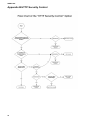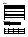
1
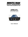
SNMP-SSL UPS SNMP Card (Web-Based monitoring SNMP Card) User’s Manual SNMP-SSL Table of Contents Electronic Emission Notice.............................................................................................. 3 Safety Information............................................................................................................. 3 Chapter 1 Introduction...................................................................................................... 4 Features ........................................................................................................................ 4 Package Contents......................................................................................................... 5 System Application........................................................................................................ 5 Chapter 2 Installation........................................................................................................ 6 Hardware Installation .................................................................................................... 6 Configuration trough the Serial Port.............................................................................. 7 Configuration through Telnet ......................................................................................... 17 Configuration through a Web Browser .......................................................................... 18 Chapter 3 Managing the SNMP-SSL/UPS via Web Browser ......................................... 21 UPS Monitoring ............................................................................................................. 21 Comprehensive View .................................................................................................... 21 Help Menu..................................................................................................................... 22 UPS Identification.......................................................................................................... 22 Battery Parameters ....................................................................................................... 23 Input Parameters........................................................................................................... 23 Output Parameters........................................................................................................ 24 Alarm Table ................................................................................................................... 24 Client Table ................................................................................................................... 25 Chapter 4 UPS Management ............................................................................................ 26 UPS Configuration ........................................................................................................ 26 UPS Control .................................................................................................................. 27 UPS Battery Test........................................................................................................... 27 UPS Battery Test Schedule........................................................................................... 28 UPS Shutdown.............................................................................................................. 29 Weekly Schedule .......................................................................................................... 30 Special Day Schedule ................................................................................................... 30 EMD Configuration........................................................................................................ 31 Chapter 5 SNMP-SSL Management ................................................................................. 32 Date and Time............................................................................................................... 32 SNMP-SSL Configuration.............................................................................................. 32 SNMP-SSL Control ....................................................................................................... 34 SNMP-SSL Upgrade ..................................................................................................... 35 SNMP-SSL RADIUS Configuration ............................................................................... 36 SNMP-SSL Change Trap Level..................................................................................... 37 SNMP/HTTP Access Control ........................................................................................ 38 SNMPv3 USM Table...................................................................................................... 39 SNMP Trap Receivers................................................................................................... 40 WakeOnLAN Targets..................................................................................................... 41 Homepage Refresh Rate .............................................................................................. 42 Email Notification .......................................................................................................... 42 External Links................................................................................................................ 44 Chapter 6 History and Events Logs ................................................................................ 45 UPS History Log Data ................................................................................................... 45 UPS Extended log Data ................................................................................................ 46 UPS Events Log Data ................................................................................................... 47 SNMP-SSL Events Log Data......................................................................................... 48 Clear & Save log Data................................................................................................... 49 Chapter 7 Monitoring SNMP-SSL/UPS via Java Applet ................................................. 50 Java Monitor.................................................................................................................. 50 Status Bar...................................................................................................................... 51 Alarm Windows ............................................................................................................. 51 UPS History Log............................................................................................................ 52 UPS Extended History Log ........................................................................................... 53 Extra Browsing Options PDA & WAP ............................................................................ 54 2 SNMP-SSL PDA ............................................................................................................................... 54 WAP .............................................................................................................................. 54 Chapter 8 Managing SNMP-SSL/UPS via SNMP............................................................. 55 SNMP Access Control Setting....................................................................................... 55 SNMP Trap Receivers Setting....................................................................................... 55 Setting up the NMS ....................................................................................................... 55 Chapter 9 Shutdown Software ......................................................................................... 56 Installing the Shutdown Software in Windows............................................................... 56 View the Connected Client from a Web Browser .......................................................... 57 Shutdown Process in Windows ..................................................................................... 58 Uninstalling the Shutdown Software.............................................................................. 58 Installing the Shutdown Software in SCO OpenServer UNIX........................................ 59 UGuard Parameters Description ................................................................................... 61 Deleting uGuard ............................................................................................................ 61 Installing the Shutdown Software in Linux kernel 2.0.x ................................................. 62 Installing the Shutdown Software in Solaris .................................................................. 63 UGuard Command Descriptions ................................................................................... 64 Appendix A SNMP-SSL Upgrade Utility Software .......................................................... 66 General Information....................................................................................................... 66 Updating the SNMP-SSL card’s Firmware form Windows ............................................ 66 Updating the SNMP-SSL card’s Firmware form UNIX................................................... 67 Appendix B HTTP Security Control ................................................................................. 68 Flow Chart of the “HTTP Security Control” Option ........................................................ 68 Appendix C Technical Information .................................................................................. 69 Specification .................................................................................................................. 69 Dipswitch Definition ....................................................................................................... 69 LED Definition ............................................................................................................... 69 Obtaining Technical Assistance ..................................................................................... 70 Limited Product Warranty .............................................................................................. 71 DOS, Windows 95, 98, Me, Windows NT, 2000, XP, 2003 are registered trademarks of Microsoft Corporation. All other trademarks belong to their respective proprietors. Electronic Emission Notice Federal Communications Commission (FCC) This equipment has been tested and found to comply with the limits for a Class B digital device, pursuant to Part 15 of the FCC Rules. These limits are designed to provide reasonable protection against harmful interference when the equipment is operated in a commercial environment. CE Notice This device complies with the EMC directive of the European Community and meets or exceeds the following technical standards: • EN 55022:1998 ”Limits and Methods of Measurement of Radio interference Characteristics of information Technology Equipment.” This device complies with the CISPR Class B standard • EN 55024:1998 ”Electromagnetic compatibility Generic immunity standard Part1: Residential, and light industry.” Safety Information All the service of this equipment must be perform by qualified service personnel. Remove rings, watches and other jewelry before servicing the unit. Before plugging in or pulling out the SNMP-SSL card to and/or from the UPS, please make sure that the UPS is in the OFF position. © Copyright 2008 3 SNMP-SSL Chapter 1 Introduction Features • • • • • • • • • • • • • • • • • • • • • • • • • • 4 Network connection through RJ45 connector Allows connection of the UPS directly to the network through a RJ45 connector without using RS232 ports on the computer and without loading any individual UPS management software on the network server. Network UPS management Allows remote management of the UPS from any workstation through Internet or Intranet. Remote UPS monitoring via SNMP, HTTP and JAVA applets Allows monitoring of the UPS using SNMP-SSL card’s MIB (Management Information Base) files - provided with SNMP-SSL card, Internet Browser or Java monitoring applets. Configure UPS and SNMP-SSL card’s functions from any client (password protected) Set UPS and SNMP-SSL card’s parameters from any SNMP management station or through Internet Browsers. Monitor power quality via Java Applets Provides visual indication on screen through dynamic graphics. Keep event logs & metering data in flash memory Provides a history file of the UPS: power events, power quality, status, and battery condition. Notification of system administrator via SNMP Traps, Java applets RTC supported Shutdown Watchdog enabled Telnet support for configuration BOOTP/DHCP supported GUI for homepages and Java applets Online configuration supported Standard UPS MIB (RFC1628) supported Enhanced HTTP security No restart needed for IP change System parameters/log write to flash memory simultaneously SSH and SSL supported WOL function supported Supports SSL-EMD (Environmental Monitoring Device) to measure the temperature and humidity. Supports SSL-SMOKE (Smoke Detector Device) to detect smoke Supports SSL-WATER (Water Leak Sensor Device) to detect water leaks Supports SSL-DOOR (Door Sensor Device) to detect open doors Supports SSL-VIBRATION (Vibration Sensor Device) to detect vibrations NTP & ICMP supported SNMPv3 supported SNMP-SSL Package Contents 1. SNMP-SSL card with mounting bracket 2. RJ45 to RS232 serial cable for console operation 3. CD-ROM contains the User’s Manuals, Quick Installs, MIB file, SSL-Upgrade Utility software, SSL-Manager Software, SSL-Shutdown Software 4. Quick Install and Warranty Registration System Application SNMP-SSL card is an interface between UPS and the network. It can obtain the status from a UPS and issue commands to it. SNMP-SSL card supports two kinds of protocol – SNMP and HTTP for user access. Through the SNMP NMS and Web Browser, user can obtain the UPS status, issue commands to UPS and setting up the SNMP-SSL card through the network. Figure 1-1: SNMP-SSL Card. UPS SNMP-SSL SNMP Card Power Line Computer 1 NMS Station or W eb Browser Ethernet Computer 2 Computer 3 Figure 1-2: SNMP-SSL Card System Application Diagram. 5 SNMP-SSL Chapter 2 Installation To install SNMP-SSL card on a network you need a workstation running Microsoft Windows (9x, Me, NT4.0, 2000, XP or later). If your network dynamically configures the IP address, all you need is a workstation with a Web Browser. There are three methods for setting the SNMP-SSL card’s configuration: 1. Set up via serial port 2. Set up via Telnet 3. Set up via Web Browser Hardware Installation Note: The SNMP-SSL cards are designed to be Hot Swappable, but there is a remote chance that when Hot-Swapping the SNMP-SSL card that the UPS will shutdown. MINUTEMAN recommends following steps 1 through 4 when installing the SNMP-SSL card, but to hot-swap, skip to step number 3. 1. 2. 3. 4. Turn off all the equipment that is plugged into the UPS. Turn off the UPS and unplug the UPS’s power cord from the AC wall outlet. Remove the Option Slot cover plate from the rear panel of the UPS. Insert the SNMP-SSL card into the option slot and secure with the retaining screws. Figure 2-1: SNMP-SSL card and UPS connection 6 SNMP-SSL Configuration through the Serial Port 1. Use the RJ45 to RS232 serial cable to connect between the SNMP-SSL card’s COM port and the COM port on the workstation. 2. Set both the DIP-switches of the SNMP-SSL card to the OFF position (operating mode) for configuration. Figure 2-2: Serial cable connection of SNMP-SSL 3. From a workstation running Microsoft Windows (9x, Me, NT4.0, 2000, XP, 2003 or later), open HyperTerminal of the Accessory Program Group. Figure 2-3: HyperTerminal in the Accessory programs group 7 SNMP-SSL 4. Enter a name and choose an icon for the connection and then click OK. Figure 2-4: New HyperTerminal connection 5. Select direct COM port connection. Select the appropriate COM port and then click OK. Figure 2-5: Select Direct to COM port connection 8 SNMP-SSL 6. Set up the COM port parameters - 9600 bps, 8 data bits, no parity, 1 stop bit and no flow control, then click Apply and then OK. Figure 2-6: Setup of the COM port parameters 7. Power on the UPS and wait for SNMP-SSL card to boot up. Hit the “Enter” key once to display the menu below. Enter the password (default password is admin) and hit the “Enter” key. Figure 2-7: SNMP-SSL Configuration Utility Main Menu 9 SNMP-SSL 8. The SNMP-SSL Configuration Utility Main Menu will be displayed. Select “1” to enter the SNMP-SSL Configuration Menu. Figure 2-8: SNMP-SSL Configuration Utility Main Menu 9. The SNMP-SSL Configuration Menu will be displayed. Select “1” to enter the System Group Configuration Menu. Figure 2-9: SNMP-SSL Configuration Menu 10 SNMP-SSL 10. The SNMP-SSL System Group Configuration Menu will be displayed. Set the IP Address, Gateway Address and the Network Mask (subnet) parameters. Note: The minimum requirement is to set the IP Address (The default IP address is 192.168.1.100), the Gateway Address, and the Network Mask to be able to connect to the SNMP-SSL card with a Web Browser. All other setting may be configured using a Web Browser except for changing the Login Password. Figure 2-10: System Group Configuration Menu After completing these settings, select “0” to return to the Configuration Menu. 11. In the Configuration Menu select, “4” to enter the Date and Time Menu. Set all of the date and time parameters. Figure 2-11: Date and Time Menu After completing these settings, select “0” to return to the Configuration Menu. 11 SNMP-SSL 12. In the Configuration Menu, select “2” to change the Login Username and enabled/disabled the different network protocols. Figure 2-12: SNMP-SSL Control Group Configuration Menu After completing these settings, select “0” to return to the Configuration Menu. 13. In the Configuration Menu select “3” to configure the SNMP-SSL parameters. Figure 2-13: Parameter Group Configuration Menu After completing these settings, select “0” to return to the Configuration Menu. 12 SNMP-SSL 14. In the Configuration Menu, select “4” to configure the Email settings. Figure 2-14: Email Group Configuration Menu After completing these settings, select “0” to return to the Configuration Menu. 15. In the Configuration Menu, select “5” to configure the Web Authentication Group settings. Figure 2-15: Web Authentication Group Configuration Menu 13 SNMP-SSL 16. In the Web Authentication Group Configuration Menu, select “1” to configure the Radius Group settings. Figure 2-16: Radius Group Configuration Menu After completing these settings, select “0” to return to the Configuration Menu. 17. In the Configuration Menu, select “6” to configure the Ping Group settings. Figure 2-17: Ping Group Configuration Menu After completing these settings, select “0” to return to the Configuration Menu and then select “0” again to return to the SNMP-SSL Configuration Utility Main Menu. 14 SNMP-SSL 18. In the SNMP-SSL Configuration Utility Main Menu, select “3” to configure the Access Control settings. To set up more restrictive access, you can use the access table to add the IP address of the PC’s on which you wish to modify the access permissions. Note: The configuration of Access Control Table is configured for HTTP and SNMP HTTP Network Management. Access through Telnet or RS-232 is permitted only when using the “Community Read/Write” password in Control Group. The community strings entered in the Community String fields are visible only through the RS-232 connection. The Telnet connection does not display the string. An asterisk “*” will be shown in the field. If a “NotAccess” access right is associated with an IP address, the associate workstation will not be able to display any information regarding the SNMP-SSL card, even if the Community Read-Only string is entered. Figure 2-18: Access Control Table After completing these settings, select “0” to return to the SNMP-SSL Configuration Utility Main Menu. 15 SNMP-SSL 19. In the SNMP-SSL Configuration Utility Main Menu, select “4” to configure the Domain User settings. Figure 2-19: Domain User Table After completing these settings, select “0” to return to the SNMP-SSL Configuration Utility Main Menu. 20. In the SNMP-SSL Configuration Utility Main Menu, select “5” to configure the Trap Receiver settings. If you want to use a PC to perform the SNMP manager ‘trap’ function in order to manage UPS through SNMP-SSL card, the IP address of the PC must be added to the SNMP-SSL list. Note: The Set Trap Receivers configuration is used only for an NMS. Figure 2-20: Trap Receiver Table After completing these settings, select “0” to return to the SNMP-SSL Configuration Utility Main Menu. 16 SNMP-SSL 21. In the SNMP-SSL Configuration Utility Main Menu, select “6” to configure the SNMPv3 USM settings. Figure 2-21: SNMPv3 USM Table After completing these settings, select “0” to return to the SNMP-SSL Configuration Utility Main Menu. The SNMP-SSL card’s configuration is complete, select “0” to end the HyperTerminal session. Disconnect the RJ45 to RS232 serial cable from the SNMP-SSL card’s COM port and the computer COM port. Connect the network cable to the Network port on the SNMP-SSL card. Open a Web Browser and input the IP address to view the SNMP-SSL card’s web pages. Configuration through TELNET 1. 2. 3. 4. 5. 6. 7. 8. Make sure that you have a TCP/IP network already installed. Connect the network cable to the Network port on the SNMP-SSL card. Run command shell (i.e. Windows MS-DOS prompt). SNMP-SSL card will initially try to acquire an IP address from the DHCP network service. If the DHCP network service is running, type “Telnet <IP address obtained from DHCP>” and then press enter. Now proceed to Step 8 below. If the DHCP network service is not running, contact your network administrator to get an IP address for you workstation that has the same network’s address as the SNMP-SSL card’s default IP address. The default IP address of SNMP-SSL is 192.168.1.100 Type “Telnet 192.168.1.100” and press enter. From this point, the configuration procedures are the same as the Configuration through the Serial Port (start at number 7 on page 9). 17 SNMP-SSL Configuration through a Web Browser Normally, the first time you use SNMP-SSL card, your workstation is unable to communicate to SNMP-SSL card since they are not in the same IP subnet. However, you may use the “route add” command to manipulate the network routing table in your workstation in order to complete the SNMP-SSL card’s configuration. If the IP address of the machine is in the same subnet as SNMP-SSL card, just run the Web Browser. 1. From a workstation running Microsoft Windows (9x, Me, NT4.0, 2000, XP, 2003 or later) set up the TCP/IP protocol, if necessary. 2. Connect the network cable to the Network port on the SNMP-SSL card. 3. Run command shell (i.e. Windows MS-DOS prompt) and enter the following command to add a routing condition: Route add 192.168.1.100 210.67.192.147 Assuming the IP address of the workstation is 210.67.192.147. The default IP address of SNMP-SSL card is 192.168.1.100 3. Start your Web Browser. 4. Enter the URL http:\\192.168.1.100 in the address box. The SNMP-SSL card’s home page will be displayed. Figure 2-22 SNMP-SSL home page: Comprehensive View 18 SNMP-SSL 5. Open the SNMP-SSL Management folder. 6. Open the SNMP-SSL Configuration page. 7. Click the Become Administrator button at the bottom of the page. Enter SNMP-SSL as the login name and admin as the password. (Case sensitive) 8. Enter the IP Address. 9. Enter the Gateway Address. 10. Enter the Subnet Mask. 11. When finished click Set Value to save the settings. Figure 2-23 SNMP-SSL Configuration page 19 SNMP-SSL 12. Open the Date and Time page. 13. Enter the correct date and time information. 14. When finished click Set Value to save the settings. Figure 2-24 SNMP-SSL Date and Time page 15. Open the SNMP-SSL Control page. 16. Make the appropriate changes. 17. When finished click Set Value to save the settings. Figure 2-25 SNMP-SSL Control page 20 SNMP-SSL Chapter 3 Managing the SNMP-SSL/UPS via Web Browser This chapter describes how to use the Web-based interface to monitor the SNMP-SSL card. 1. Start your Web Browser and enter the IP address 2. The home page will be displayed. UPS Monitoring This main menu contains all the measurements and data read from the UPS. All the sub-menus are read-only for all users; write-mode access is not allowed. Comprehensive View This page gives a snapshot of all the principal UPS parameters. The page will refresh automatically. To set the refresh time, select the menu SNMP-SSL Management – Homepage Refresh Rate. Figure 3-1 SNMP-SSL Comprehensive View 21 SNMP-SSL Help Menu Select the Help icon located at the bottom of each page for a detail description of each item. Figure 3-2 SNMP-SSL Help Menu UPS Identification Select the UPS Identification from the UPS Monitoring menu of the home page to get the UPS and SNMP-SSL card’s Identification parameters. Figure 3-3 SNMP-SSL UPS Identification 22 SNMP-SSL Battery Parameters Select the Battery Parameters from the UPS Monitoring on the main menu to get the UPS’s battery parameters. Figure 3-4 SNMP-SSL Battery Parameters Input Parameters Select Input Parameters from the UPS Monitoring on the main menu to get the UPS’s input parameters. Figure 3-5 SNMP-SSL Input Parameters 23 SNMP-SSL Output Parameters Select Output Parameters from the UPS Monitoring on the main menu to get the UPS’s output parameters. Figure 3-6 SNMP-SSL Output Parameters Alarm Table Select Alarm Table from the UPS Monitoring on the main menu to get the status of the UPS’s alarms. Figure 3-7 SNMP-SSL Alarm Table 24 SNMP-SSL Client Table Select Client Table from the UPS Monitoring on the main menu to get a list of the connected clients, which are running the shutdown software. Figure 3-8 SNMP-SSL Client Table 25 SNMP-SSL Chapter 4 UPS Management This chapter describes how to use the Web-based administration interface to maintain SNMP-SSL card. The chapter also introduces and gives detailed information of all the administrative functions that are build-in the SNMP-SSL card. The IP address of the workstation must be entered in the SNMP-SSL access control table to prevent unauthorised users from configuring SNMP-SSL card via HTTP or SNMP protocols. Note: If you do not add the IP address of the workstation to the Access Control Table (via RS232 or Telnet) or the SNMP/HTTP Access Control (via Web Browser) in the SNMP-SSL card, you can only view the UPS status; it will not be able to perform any configuration on SNMP-SSL/UPS. (See the Access Control Table Setting and the SNMP/HTTP Access Control for details.) This menu contains the control parameters of the UPS. All the sub-menus are available in read-only for all users, whereas only the administrator has access to read/write. UPS Configuration This menu displays the UPS nominal input and output data. If you are using an External Battery Pack with this UPS, the UPS must be configured so that; the UPS will report the correct estimated runtime and the Battery capacity bar graph LEDs will display properly. To configure the UPS for External Battery Packs you must have administrative rights. 1. External Battery Pack Number: Select the appropriate number of External Battery Packs connected to the UPS. 2. Set Value: Saves the settings. Figure 4-1 SNMP-SSL UPS Configuration 26 SNMP-SSL UPS Control This menu allows you to turn the UPS off/on, put the UPS in a Sleep mode and turn the UPS’s output receptacles off/on. The UPS has two controllable load banks. When finished click Set Value to save the settings. Figure 4-2 SNMP-SSL UPS Control UPS Battery Test This menu allows you to perform two battery tests and provides information about the last battery test performed: 1. Quick Battery Test (Test the battery for 10-seconds) 2. Test Until Battery Low (test the UPS until a Low Battery Warning occurs, then resets to the AC mode). 3. Set Value: Saves the settings. Figure 4-3 SNMP-SSL UPS Battery Test 27 SNMP-SSL UPS Battery Test Schedule This menu allows you to schedule UPS battery testing for a specific day and time. 1. Quick Battery Test - Test the battery for 10-seconds 2. Test Until Battery Low - Test the UPS until a Low Battery Warning occurs, then resets to the AC mode. 3. Set Value: Saves the settings. Figure 4-4 SNMP-SSL UPS Battery Test Schedule 28 SNMP-SSL UPS Shutdown This menu allows you to modify the parameters associated with the shutdown events. The available shutdown events are: 1. AC Failed: Utility power has failed 2. Battery Low: The battery capacity has reached a low level 3. UPS Overload: The output of the UPS is overloaded 4. UPS Over Temperature: UPS is overheating internally 5. Weekly Schedule: UPS Shutdown/Restore pre-set for each week 6. Special Day: UPS Shutdown/Restore pre-set on certain day 7. EMD Temperature over Threshold: The EMD has detected an out of tolerance condition either a high or a low temperature 8. EMD Alarm-1: Alarm-1 sensor detects an active alarm. 9. EMD Alarm-2: Alarm-2 sensor detects an active alarm. When a shutdown event has occurred, SNMP-SSL card will take the selected action as define in the Shutdown Actions column. Available actions are: a. Disabled: Action is disabled b. Warning: Warning message will be broadcast to the connected clients c. Client Shutdown: Warning message will be broadcast and shutdown command will be sent to the connected clients. UPS will then go into a sleep mode d. UPS Turn Off: Warning message will be broadcast and shutdown command will be sent to both the connected clients and the UPS. 1. Warning Period (Min): Specifies the time when the Shutdown command will be sent to the clients. 2. 1st Warning (Sec): Specifies the time of the first warning message to be broadcasted to the connected clients. 3. Warning Interval (Sec): Specifies the frequency of the next warning message. 4. UPS Shutdown Delay (Sec): The time the Shutdown command is sent out after the event has occurred. 5. Set Value: Saves the settings. Figure 4-5 SNMP-SSL UPS Shutdown 29 SNMP-SSL Weekly Schedule This menu allows you to modify the parameters of the shutdown/restore events associated with the days of the week. Once this is set the UPS will perform this action every week at the designated time. When finished click Set Value to save the settings. Figure 4-6 SNMP-SSL Weekly Schedule Special Day Schedule This menu allows you to modify the parameters of the shutdown/restore events associated with certain days of the year. When finished click Set Value to save the settings. Figure 4-7 SNMP-SSL Special Day Schedule 30 SNMP-SSL EMD Configuration This menu allows you to configure all necessary parameters of an EMD and the Contact Devices. The temperature, humidity and the contact devices values will be displayed on the Comprehensive View page. See the SSL-EMD Users Manual and the Contact Devices Quick Install for installation instruction. 1. Sensor Name: Configure the name of a sensor (or device) with up to 15 characters. 2. Set Point: The threshold of a sensor (Temperature or Humidity) will trigger an alarm, whenever the measurement is over (high) or under (low) the set point. If the checkbox is not filled, the threshold is disabled and the alarm will not be triggered. 3. Calibration Offset: If the measurement value of a sensor does not, for whatever reason, comply with the actual environment, the 'Calibration Offset' setting can be configured to adjust the final value of the sensor. 4. Alarm Type: If an alarm sensor (water leak, security, etc) is connected to the SNMP-SSL card, the user can configure the alarm as 'Disabled', 'Normal Open', or 'Normal Close'. A 'Disabled' setting will mean the alarm is inactive. 5. EMD Status: The EMD can be configured as 'Disabled' or 'Auto'. The setup should be configured as 'Disabled' if an EMD is not attached to the port. The EMD type will be auto detected by the SNMP-SSL card if configured as 'Auto' and if the EMD is plugged into the port. 6. EMD Temperature over Threshold: Shutdown occurs when EMD temperature sensor detects a high or low temperature when, the UPS Shutdown is configured. 7. EMD Alarm-1: Shutdown occurs when alarm-1 sensor detects an active alarm when, the UPS Shutdown is configured. 8. EMD Alarm-2: Shutdown occurs when alarm-2 sensor detects an active alarm when, the UPS Shutdown is configured. 9. Set Value: Saves the settings. Figure 4-8 EMD Configuration screen 31 SNMP-SSL Chapter 5 SNMP-SSL Management The following menus allow the user to configure the SNMP-SSL control parameters. All the menus are available for all users in the read-only mode, except for the administrator, which has access in the read/write mode. Date and Time This menu allows you to set the SNMP-SSL card internal date and time. There are three ways to set the Date and Time: 1. Synchronize with computer time 2. Synchronize with NTP server 3. Set the date and time manually 4. Set Value: Saves the settings. Figure 5-1 Date and Time SNMP-SSL Configuration This menu allows the administrator to set the local network configuration parameters for the SNMP-SSL card. The basic variables for SNMP management can also be set. 1. SNMP-SSL IP Address: The IP address of the SNMP-SSL card (e.g. 192.168.1.100). Note that changing the IP Address of the SNMP-SSL card does not require rebooting. 2. SNMP-SSL Gateway Address: The IP address of the network gateway (e.g. 192.168.1.254). 3. SNMP-SSL Subnet Mask. The Subnet Mask for your network (e.g. 255.255.255.0). 4. System Name: SNMP Network Administrator string. 5. System Contact: SNMP Network Administrator string. 6. System Location: SNMP Network Administrator string. 7. Last Battery Replacement Date: The date when the UPS’s batteries were last replaced. Only the Administrator should reset this value. 32 SNMP-SSL 8. Next Battery Replacement Date: The date when the UPS’s batteries should be replaced next. Only the Administrator should reset this value. 9. Battery Replacement Date Type: The default type is UPS. When the SNMP-SSL card is installed in the UPS, the SNMP-SSL card will poll the UPS for this information. At the end of the batteries useful service life and battery replacement has been performed, the user can input the new dates for the Last and Next Battery Replacement Dates. Change the type to System and enter the new dates. 10. History Log Interval: This value is the time in seconds to poll Input Voltage, Output Voltage, Load, Capacity, Battery temperature and Input frequency. These values are saved in the History Log. The maximum value for this setting is 28800 seconds (i.e. 8 hours). 11. Extended History Log Interval: This field shows the set interval, in minutes, to create an extended history log. After every interval, the UPS parameters will be consolidated and minimum, maximum and average values of these parameters will be stored as extended history log. This value can range between 3 and 9000 minutes. 12. SNMP-SSL Polling Rate (sec): Polling rate on which SNMP-SSL card updates the parameters from UPS. 13. SNMP-SSL Baudrate (sec): The data transmission rate between the UPS and SNMP-SSL card (Not Configurable). 14. Temperature Unit: Set the Temperature Unit to Celsius or Fahrenheit. 15. Set Value: Saves the settings. Figure 5-2 SNMP-SSL Configuration 33 SNMP-SSL SNMP-SSL Control This menu allows you to enable or disable the communication protocols available in the SNMP-SSL card. Some of the items in this menu are only configurable to those having read/write access rights. 1. BOOTP/DCHP Status: Enabling or disabling the Boot Protocol (BOOTP) / Dynamic Host Configuration Protocol (DHCP). These protocols are Internet standards used to get a dynamic IP address from a BOOTP / DHCP server. 2. Ping Echo: Enabling or disabling the SNMP-SSL card to respond to Ping requests. 3. Network Upgrade: Enabling or disabling the Trivial File Transfer Protocol (TFTP) upgrade control. You can use upgrade.exe on Windows via TFTP to upgrade SNMP-SSL card’s firmware. 4. Telnet Connection: Enabling or disabling the terminal to server application (Telnet) control process. The standard port is 23. 5. HTTP Support: Enabling or disabling the HTTP connection with the SNMP-SSL card. The user may configure HTTP protocol to use a port number other than standard HTTP port (80). 6. HTTP(s) Authentication: Select the "Local User", "RADIUS" or "Both" account types to set the login account and password. 7. SNMP Support: Enabling or disabling the SNMP connection with SNMP-SSL card. The user may configure the SNMP protocol to use a port number other than the standard SNMP port (161). 8. SNMP Version: Select which SNMP version to use SNMPv1 or SNMPv3. 9. UPnP Support: Enable or Disable the Universal Plug and Play (UPnP) feature. 10. SMTP: Configure the SMTP port to send and receive email from the SNMP-SSL card. Default port is 25. 11. Apply: Saves the settings. 12. Reset Agent to Default: Resets the SNMP-SSL card to factory default parameters. 13. Restart Agent: Reboots the SNMP-SSL card. Figure 5-3 SNMP-SSL Control 34 SNMP-SSL SNMP-SSL Upgrade This menu allows the Administrator to flash upgrade the SNMP-SSL card’s firmware. 1. Browse: Searches for the location where the firmware file (Bin) is stored. 2. Upgrade Agent Firmware: Starts the upgrade process. 3. Upload Status: Shows the status of the upgrade process. Figure 5-4 SNMP-SSL Upgrade 35 SNMP-SSL SNMP-SSL RADIUS Configuration Remote Authentication Dial-In User Service (RADIUS) is a widely deployed protocol enabling centralized authentication, authorization, and accounting for network access. This menu allows the administrator to configure the RADIUS parameters. 1. 2. 3. 4. 5. 6. 7. 8. RADIUS UDP Port: It shows the RADIUS UDP port. Primary RADIUS Server: Set the Primary RADIUS Server's IP address. Secondary RADIUS Server: Set the Secondary RADIUS Server's IP address. Share Secret of Primary Server: Set the Share Secret of Primary Server. Share Secret of Secondary Server: Set the Share Secret of Secondary Server. Packet Timeout Interval (sec): Set the Packet Timeout Interval. Packet Retry Times: Set the Packet Retry Times. Set Value: Saves the settings. Figure 5-5 SNMP-SSL RADUIS Configuration 36 SNMP-SSL SNMP-SSL Change Trap Level This menu lists the support SNMP Traps and allows the user to change the Trap Level for each Trap. 1. Index: The index number of the entry in the table. 2. Trap Name: The short description of each Trap. 3. Trap Level: There are three levels that can be selected by the users: a. Severe b. Warning c. Informational Figure 5-6 SNMP-SSL Change Trap Level 37 SNMP-SSL SNMP/HTTP Access Control This menu allows the administrator to configure the SNMP/HTTP Access Control to enable specific workstations for read/write access to the SNMP-SSL card. See Appendix B HTTP Security Control. NMS Table: 1. Index: The index number of the entry in the table. 2. NMS IP Address: IP address 255.255.255.255 grants the access right to all IP address. 3. Community: Low-level password of the associated IP address with the access type set by the Administrator. 4. Access Type: Access right associated with the IP Address. Available options are: a. NotAccess b. Read c. Read/Write. If the IP Address is set to NotAccess or Read, not even the administrator will have access. Domain User Table: 1. Index: The index number of the entry in the table. 2. User Name: This shows the user name with the specified access level. 3. Access Type: Available options are: Read Only, Read / Write, No Access. Note: As administrator, you can configure different workstations or subnets using different passwords with different Access Types. This will prevent someone from arbitrarily changing the passwords. Figure 5-7 SNMP/HTTP Access Control 38 SNMP-SSL SNMPv3 USM Table This menu allows the administrator to configure the SNMP-SSL card for the SNMPv3 USM (User Security Model). SNMPv3 USM provides confidentiality and integrity for network management communications. SNMPv3 USM also allows for user-based authentication and access control. Rather than using the two-level “read” and “write” community strings of prior SNMP implementations, administrators can create specific accounts for each SNMP user and grant privileges through those users accounts. 1. Index: The index number of the entry in the table. 2. User Name: This field allows the administrator to set the specific user name who will have access to the SNMP-SSL card via SNMPv3. 3. Auth Password: This field allows the administrator to set the authentication password of the associated user. 4. Priv Password: This field allows the administrator to set the privacy password of the associated user. 5. Security Level: This field allows the administrator to set the access type for the associated user. The available options are: a. NoAuthNoPriv: Access with no authentication and no privacy passwords. b. authNoPriv: Access with authentication password but no privacy password. c. authPriv: Access with no authentication password but with privacy password. 6. Authentication: This field allows the administrator to set the authentication format, HMAC-MD5 or HMAC-SHA. 7. User Status: This field shows the status of the associated user. Figure 5-8 SNMPv3 USM Table 39 SNMP-SSL SNMP TRAP Receivers This menu allows the administrator to configure the SNMP-SSL card to send SNMP Traps to eight different Network Management Stations (NMS). The MIB files must be installed on the NMS. 1. Index: The index number of the entry in the table. 2. NMS IP Address: The IP Address of the NMS station to which the trap should be sent. 3. User Name: The User Name of the specified trap receiver. 19-characters are the maximum length of the string. 4. Trap Type: Types of traps to be received. a. None: No traps are to be received. b. RFC-1628 Trap: Traps are received base on RFC-1628. c. SNMP-SSL Trap: Traps are received base on SNMP-SSL MIB. 5. Severity: Set the level of the trap to be received. There are three levels: a. Information: Traps of general information are received. b. Warning: Traps that warn of the impending danger are received. c. Severe: The significant traps such as the UPS failure and severe events are received. 6. Description: Customer description string. Figure 5-9 SNMP TRAP Receivers 40 SNMP-SSL WakeOnLAN Targets WOL" function allows you to start up client PCs through the network. 32 clients can be set up. After the client shuts down because of the UPS shutdown events, the WOL packet will be sent to client to wake up the PC. 1. Repeating Times: The number of times the packets will be sent. 2. Interval Timer (Sec): The time before the next packet is sent. 3. Set Value: Saves the settings. 4. Index: The index number of the entry in the table. 5. MAC Address: The MAC address of the targeted PC. 6. Action: Enable or Disable the targeted PC. 7. Description: Customer description string. 8. Modify: Allows you to modify the action. 9. Add New: Allows you to add 32 targets. 10. Wake On LAN Test: Test the Wake On LAN function. Figure 5-10 WakeOnLAN Targets 41 SNMP-SSL Homepage Refresh Rate This menu allows the administrator to set the refresh rate of the SNMP-SSL card’s web pages. When finished click Set Value to save the settings. Figure 5-11 Homepage Refresh rate Email Notification This menu allows the administrator to configure the email setting to receive notifications and/or reports from SNMP-SSL card by email once an event has occurred. 1. Mail Server: The Hostname of the SMTP Mail Server that will be used to send emails from the SNMP-SSL card. If entering a Hostname, you are also required to enter the DNS Address. 2. User Account: The default has no entry. The User Account is only required if Mail Server requires authentication to send emails. 3. User Password: The User Password is for the User Account. 4. SMTP Authentication: This is only required if Mail Server requires authentication to send emails. 5. Sender’s Email Address: A legitimate email address is required for the SNMP-SSL card to send emails. 6. Mail Subject Prefix: The subject line to identify the device, which sends out the email. 7. DNS Address: The IP Address of the DNS server. 8. Mailing Daily Status Report At (hh:mm): The SNMP-SSL card will send a Daily Status report to select Mail Receiver at the specified time. 9. Mail Account: Enter the email address of the mail recipient. 10. Description: This column is for entering describing of each Mail Receiver you configure for reference purposes. 42 SNMP-SSL 11. Mail Type: This column is for selecting what type of email is sent to a specific Mail Receiver. The choices are: a. None: Allows you to disable sending emails to a specific recipient. b. Events: When a specific event occurs the designated recipient will receive an email. c. Daily Status: Allows the designated recipient to receive the Daily Status Reports. The recipient will receive two Daily Status Reports the History Log and the Event Log (both in .csv format). The Mailing Daily Status Report At (hh:mm) must be set up to perform this function. d. Events/Status: Allows the designated recipient to receive event notifications and the Daily Status Reports. When a specific event occurs the designated recipient will receive an email with the event information and the Daily Status Report files. 12. Event Level: Allows you to configure the Severity level according to the designated recipient. The Severity level is based on the SNMP Traps, there are three levels: a. Information: All traps are received. b. Warning: The critical traps such as AC fail are received. c. Severe: The significant traps such as UPS failure and low-battery are received. Figure 5-12 Email Notifications 43 SNMP-SSL External Links This menu allows you to set up the External Links. Each index can be linked to an external web page such as another UPS with an SNMP-SSL card, or a technical support homepage. 1. Screen Text: This is the description of the hyperlink name, which will be displayed on the menu tree. 2. Link Address: This field defines the web page location to be connected. The address format can be either IP or URL. 3. Status: This field controls the hyperlink on menu tree. Setting to "Disable" will remove this hyperlink from menu tree. Figure 5-13 External Links 44 SNMP-SSL Chapter 6 History and Events Logs The following menus allow you to capture (save in .csv format) and view History and Event logs for the UPS and Event logs for the SNMP-SSL card. These log files are very useful when diagnosing power and network problems. Note: To Save or Clear the log files go to the Clear & Save Log Data menu. UPS History Log Data This menu displays the fundamental UPS parameters. The existing values are overwritten when the maximum number of entries (rows) has been reached. The Administrator has the access right to delete the log file. 1. Log Date: Date on which the entry was made. 2. Log Time: The time in a 24-hour format when the values were recorded. 3. Input Voltage: The input voltage in Volts. 4. Output Voltage: The output voltage in Volts. 5. Output Load: The percentage of load on the UPS. 6. Battery Capacity: The percentage of battery capacity remaining. 7. Input Frequency: The input frequency in Hertz. 8. UPS Temperature: The temperature of the UPS’s internal battery. 9. EMD Temperature: The current EMD temperature. 10. EMD Humidity: The current EMD humidity. Figure 6-1 UPS History Log Data 45 SNMP-SSL UPS Extended Log Data This menu gives a consolidated view of the UPS parameters taken over a period. For each of the UPS parameters, minimum, maximum and the average values are shown in each of the records. The Administrator can change the time interval in the SNMP-SSL Configuration page. The existing values are overwritten when the maximum number of entries (rows) has been reached. The Administrator has the access right to delete the log file. Note: To Save or Clear the log files go to the Clear & Save Log Data menu. 1. 2. 3. 4. 5. Start Date: Date on which the entry was made. Start Time: The time in a 24-hour format when the values were recorded. End Date: The ending date of the consolidation interval. End Time: The ending time of the consolidation interval. Input Voltage: The minimum, maximum and average values of the input voltage in Volts. 6. Output Voltage: The minimum, maximum and average values of the output voltage in Volts. 7. Output Load: The minimum, maximum and average values of the output load expressed in percentage. 8. Battery Capacity: The minimum, maximum and average values of the battery capacity expressed in percentage. 9. Input Frequency: The minimum, maximum and average values of the input frequency in Hertz. 10. UPS Temperature: The minimum, maximum and average values of the UPS’s internal battery temperature. 11. EMD Temperature: The minimum, maximum and average values of the EMD temperature. 12. EMD Humidity: The minimum, maximum and average values of the EMD humidity. Figure 6-2 UPS Extended Log Data 46 SNMP-SSL UPS Events Log Data This menu lists all the UPS events that have occurred since the table was last cleared. The existing values are overwritten when the maximum number of entries (rows) has been reached. The Administrator has the access right to delete the entries of the table. Note: To Save or Clear the log files go to the Clear & Save Log Data menu. 1. Date: The date when the UPS event occurred. 2. Time: The time when the UPS event occurred. 3. Event Description: The description of the UPS event. Figure 6-3 UPS Events Log Data 47 SNMP-SSL SNMP-SSL Events Log Data This menu lists all the SNMP-SSL card’s events that have occurred since the table was last cleared. The existing values are overwritten when the maximum number of entries (rows) has been reached. The Administrator has the access right to delete the entries of the table. Note: To Save or Clear the log files go to the Clear & Save Log Data menu. 1. Date: The date when the event occurred. 2. Time: The time when the event occurred. 3. Event Description: The description of the event. Figure 6-4 SNMP-SSL Events Log Data 48 SNMP-SSL Clear & Save Log Data This page menu allows the Administrator to Save or Clear the Log files. The Log files are saved in .csv format, which can be read in Excel. 1. Clear Log Data: The Administrator can clear a specific Log file by checking the box next to the Log file that you want to Clear and then click the Clear button. 2. Clear the corresponding log data as you click the hyper-link below: Administrator can choose to Clear the Log file after saving the Log file. Select Yes or No and then click the Apply button. Default value is set to No 3. Save Log Data: The Administrator can Save the Log files by clicking on one of the Log files. The Log files are saved in .csv format, which can be read in Excel. Note: When the "Clear the corresponding log data as you click the hyper-link below" selection is set to Yes, the corresponding log data will be cleared even if you cancel the operation. Figure 6-5 Clear & Save Log Data 49 SNMP-SSL Chapter 7 Monitoring SNMP-SSL/UPS via Java Applet SNMP-SSL card provides three real-time graphical user interfaces written in Java Applet to monitor the UPS in LAN or WAN. Java monitor: Displays the UPS’s key parameters. UPS History Log monitor: Displays the UPS’s History Log. UPS Extended History Log monitor: Displays the UPS’s Extended History Log. Java Monitor By clicking the Java button at the top right-hand side of the SNMP-SSL card’s Home Page, a Java Applet will be opened in a separate window. This applet displays the UPS’s key parameters – AC input voltage, AC output voltage, UPS load, battery capacity, UPS temperatures, and Input frequency. In addition, this applet has a function icon, a status bar that can display the current UPS status and an alarm window that can display the current UPS alarms. Function icon Status bar Figure 7-1 UPS Monitoring (Gauge view) 50 Alarm window SNMP-SSL By clicking on the gauge, the gauge will change to a graph chart. Figure 7-2 UPS Monitoring (Gauge and Graph view) Display switch-Two different display styles (Gauge or Overall Chart presentation) of the UPS’s key parameters. This icon is used to switch the display from gauge presentation to chart presentation and vice versa. Poll Rate- Configure the poll rate of the carts and gauges. The default is 5 seconds. Event Message- Enable and disable the display of the warning messages. Event message broadcast – Enabled or disable the event message dialog box. Exit – Exit from the Java applet. Status Bar Figure 7-3 Status Bar in the UPS Monitoring The status bar displays the current status of the UPS. The green color represent that the UPS is in the normal condition. If SNMP-SSL card receives a status change of the UPS, for example an AC failure, the AC OK box will then change to a red color and display AC fail representing that the UPS has lost utility power. Alarm Windows When SNMP-SSL receives a change in the status it will display a specific message in the Alarm Window. This type of status message is an alarm. The Alarm Window displays the active alarms of the UPS and SNMP-SSL card. 51 SNMP-SSL UPS History Log By clicking the Log button at the top right-hand side of the SNMP-SSL card’s Home Page, a UPS History Log will be opened in a separate window. This applet displays the UPS History Log in a line graph format. You can select any combination of the parameters to be displayed on the graph by checking the check box beside each parameter and then click the Refresh button. Display Point: Displays the log interval on the graph. Refresh: Updates the UPS History Log and any changes that were made. Reload: Updates the UPS History Log and resets the right display margin. Exit: Closes the UPS History Log window. Left Display Right Display Right Margin Scroll Bar Figure 7-4 UPS History Log 52 SNMP-SSL UPS Extended History Log By clicking the Java button at the top right-hand side of the SNMP-SSL card’s Home Page, a UPS Extended History Log will be opened in a separate window. This applet displays the UPS History Log in a line graph format. You can select any combination of the parameters to be displayed on the graph by checking the check box beside each parameter and then click the Refresh button. Display Point: Displays the log interval on the graph. Refresh: Updates the UPS Extended History Log and any changes that were made. Reload: Updates the UPS Extended History Log and resets the right display margin. Exit: Closes the UPS Extended History Log window. Left Display Right Display Right Margin Scroll Bar Figure 7-5 UPS Extended History Log 53 SNMP-SSL Extra Browsing Options PDA & WAP SNMP-SSL now provide more easy of using remote browsing ways. User can get the UPS status through PDA or WAP mobile phone, which own ability to connect to Internet already. According to every manufacturer setting was different, please reference to PDA and WAP User Manual for connect to Internet. If your PDA or WAP can browse Internet, You can start browsing the UPS status by input the SNMP-SSL address. PDA Please input on PDA: “SNMP-SSL address/PDA” or “SNMP-SSL address/P” Example: HTTP://192.168.11.100/PDA or HTTP://192.168.11.100/P you can see the UPS’s status page. SNMP-SSL Menu UPS Status: UPS Status: On Line Voltage In (VAC): 126.0 Voltage Out (VAC): 120.0 Output Load (%): 37 Frequency (Hertz): 60.0 System Up Time: Menu Status Identification Battery Input Output Clients 0day 12:02:14 Identification: UPS Model: ED1500RM2U Output VA: 1500 UPS Type: On-Line UPS Firmware: 04 SNMP-SSL Firmware: V2.00 Location: Office Admin: MIS System Up Time: Menu 0day 12:43:12 Battery: Battery Status: Battery Ok Time since on Battery Power (Sec): 0 Battery Capacity (VDC): 100 Battery Voltage (VDC): 55.2 Battery Temperature (Celsius) Menu 30.0 Input: Voltage In (VAC): Frequency (Hertz): Menu Clients: 1: 192.168.11.209 Output: Voltage Out (VAC): Menu Output Load (%): Menu 126.0 60.0 120.0 37 Figure 7-6 Extra Browsing Options –PDA WAP Please input: “SNMP-SSL card’s address/WAP” or “SNMP-SSL card’s address/W” Example: HTTP://192.168.11.100/WAP or HTTP://192.168.11.100/W you can see the UPS’s status page. 54 SNMP-SSL Chapter 8 Managing SNMP-SSL/UPS via SNMP If you intend to manage your SNMP-SSL/UPS via SNMP NMS (Network Management station), you may want to customize some of the SNMP settings such as System Name, System Contact and System Location and so on. Note: Before using SNMP-SSL card in an SNMP environment, the IP address, gateway must be configured properly. See Chapter 2 for details. SNMP Access Control Setting SNMP-SSL card supports SNMPv1 and SNMPv3 protocols. You can use the SNMP NMS to manage the UPS through the network. The IP address of the workstation must be entered in the SNMP-SSL card’s write access table to prevent unauthorized users from configuring SNMP-SSL card via HTTP or SNMP protocols. Note: If you do not enter the IP address of the workstation to the Access Control Table (via Serial Port or Telnet) or the SNMP/HTTP Access Control (via Web Browser) in the SNMP-SSL card, the SNMP NMS can only view the UPS status; it will not be able to perform any configuration on SNMP-SSL/UPS. (See Pg. 15 Access Control Table Setting and Pg. 38 SNMP/HTTP Access Control for details.) SNMP Trap Receivers Setting See Pg. 40 SNMP Trap Receivers for details. Setting up the NMS 1. Add the MIB file from the SNMP-SSL CD-ROM to the MIB database of the SNMP manager. 2. Search for SNMP-SSL in the network. 3. To access the SNMP-SSL SNMP agent, use ‘public’ for the GET community string and the Read/Write password (default is admin) for the SET community string. GET Community string: public SET Community string: admin For more information, see the SNMP-SSL card’s MIB file on the SNMP-SSL CD-ROM. 55 SNMP-SSL Chapter 9 Shutdown Software The shutdown software is a very useful component of the SNMP-SSL card. The shutdown software runs on servers and connects to a designated SNMP-SSL card. When the servers start up, SNMP-SSL card scans the status of the UPS and broadcast a shutdown command to the workstation when a power event is detected. The shutdown software will broadcast warning messages on the screen of the servers and then perform a graceful shutdown of the server. Installing the Shutdown Software in Windows 1. Insert the SNMP-SSL CD-ROM into the CD-ROM drive. 2. Run the “SD_SNMP-SSL Service_4.20.exe” program on the CD-ROM. 3. A dialog box will be on the screen, type in the IP address of designated SNMP-SSL card, its client name and shutdown delay time. Click the Def. Button if you choose the client name as the workstation you are working on. Figure 9-1 Set up screen 4. Then press the ‘OK’ button. 5. After the set up is complete, the shutdown service will connect to the SNMP-SSL card automatically. Note: The client Shutdown Delay must not be greater than that of the UPS Shutdown Delay. 56 SNMP-SSL View the Connected Client from a Web Browser 1. Open a Web Browser and input the IP address of the SNMP-SSL card. 2. Select the Client Table from the UPS Monitoring folder. A list of the connected devices will be shown on the screen. Figure 9-2 SNMP-SSL card’s Client Table. 57 SNMP-SSL Shutdown Process in Windows When the SNMP-SSL card detects a power event it will send the shutdown command to its connected clients. A pop-up dialog box will notify the client that the system will be shutdown. The user can select "Shutdown Now" to start the shutdown process or "Close" to cancel the shutdown process. The shutdown software will proceed with the shutdown process and the host or server will be shutdown automatically if nothing is selected after the counter has counted down to zero. Figure 9-3 Shutdown warning message. There are five states for the shutdown software. 1. UPS Connection OK. 2. Trying to locate UPS. 3. Local machine is about to shutdown. 4. The service is suspended. 5. Remote UPS is about to shutdown or has shutdown. Uninstalling the Shutdown Software 1. Right mouse click on the “battery” icon in the taskbar and select "Exit” to stop the shutdown service. 2. Select the "Add/Remove programs" from the Control Panel. 3. Select the "SNMP-SSL service", and then click "Add/ Remove" to remove the software. 58 SNMP-SSL Installing the Shutdown Software in SCO OpenServer UNIX 1. 2. 3. 4. 5. From a workstation running SCO OpenServer login as a supervisor. Insert the SNMP-SSL CD-ROM into the CD-ROM drive. If you have already mounted the CD-ROM drive, skip to step 5 Type mount /dev/cd0 /mnt Select "Filesystems" -> "Filesystem Manager" -> "Mount" -> "Add Mount Configuration" -> "Local" 6. Select a "Device File" and enter the name of the "Mount Point" (Ex: /mnt). Then select "OK" 7. Copy the shutdown programs into the directory and extract the programs to the directory of ./uGuard a. # mkdir uGuard b. # cp /mnt/client/SCO/SD_SCO_4_20_USHA.tar /uGuard/uGuard.tar c. # cd /uGuard d. # tar xvf uGuard.tar e. Type “./install.sh” to proceed with the installation procedure. f. # ./install.sh g. The shell command will invoke the 'vi uGuard.conf', the user must modify the remote host value, host name and local delay. After saving the file, the installation is complete. 59 SNMP-SSL ;Sample configuration file of uGuard ;RemoteHostIP: The IP address of remote UPS. ;Set the address to default IP (0.0.0.0) if no SNMP-SSL Service is connected. RemoteHostIP = 0.0.0.0 ;ClientName:The name of the this machine[optional]. ; Free form for this parameter. ; Maximum 28 bytes long. ClientName = Mainserver ;WarningBeep status: WarningBeep = 0 ;1 = TRUE; 0 = FALSE(default) ;ShutdownDelay: The local delay time before shutdown. ; Range from 0 to 65536 seconds. ShutdownDelay = 120 ;Special shutdown script ShutdownScript = /usr/foo ;ForceShutdownDelay: The delay time for executing shutdown program ; Range from 0 to 65536 seconds. ForceShutdownDelay = 120 ;Check AC Fail event ;1 = TRUE; 0 = FALSE(default) AcFail = 0 ;Check Battery Low event ;1 = TRUE; 0 = FALSE(default) BatteryLow = 0 ;Check UPS Overload event ;1 = TRUE; 0 = FALSE(default) UPSOverload = 0 ;Check UPS Over Temperature event ;1 = TRUE; 0 = FALSE(default) OverTemp = 0 ;Special Weekly and Special Day Schedule shutdown ;1 = TRUE; 0 = FALSE(default) WeekDaySched = 0 Figure 9-4 Modifying the uGuard.conf Note: Your server will receive the warning message but will not shutdown, if AcFail=0 (default value). It will safety shutdown, if AcFail=1. 60 SNMP-SSL uGuard Parameters Description To run or view the uGuard parameters, use the following command: # cd /uGuard # uGuard -h Figure 9-5 uGuard Parameters Description. Deleting uGuard 1. Unload uGuard #cd /etc #uGuard -U 2. Remove uGuard files #cd /etc #rm uGuard #rm uGuard.conf #cd /etc/rc.d/init.d #rm ug_usha.sh #rm /usr/adm/uGuard.log 61 SNMP-SSL Installing the Shutdown Software in Linux kernel 2.0.x The shutdown software supplied from the SNMP-SSL CD-ROM for the Linux can be install on the Linux operating system with kernel version higher than 2.0.x. To be able to execute the shutdown program correctly, please check the following procedures: 1. 2. 3. 4. 5. 6. From a workstation running Linux kernel 2.0.x and login as a supervisor. Insert the SNMP-SSL CD-ROM into the CD-ROM drive. If you have already mounted the CD-ROM drive, skip to step 7 Type mount /dev/cdrom Change the directory to the "Mount Point" (Ex: /mnt/cdrom/CLIENT/Linux). Copy the shutdown programs into the directory and extract the programs to the directory of ./uGuard # cd /mnt/cdrom/CLIENT/Linux # mkdir /uGuard # cp ./SD_Linux_4_20_USHA.tar # cd /uGuard # tar xvf uGuard.tar /uGuard/uGuard.tar 7. Type “./install.sh” to proceed with the installation procedure. # ./install.sh The shell command will invoke the 'vi uGuard.conf', the user must modify the remote host value, host name and local delay. After saving the file, the installation is complete. Note: Also see Install Shutdown Software in SCO OpenServer UNIX. 62 SNMP-SSL Installing the Shutdown Software in Solaris 1. 2. 3. 4. 5. From a workstation running Solaris and login as an administrator. Insert the SNMP-SSL CD-ROM into the CD-ROM drive. Mount CD-ROM Create new directory. (mkdir uGuard) Copy the shutdown programs into the directory. Then extract the programs to the directory of ./uGuard, and then uncompress it. 6. Type “./install.sh” to proceed with the installation procedure. 7. The shell command will invoke the 'vi uGuard.conf', the user must modify the remote host value, host name and local delay. After saving the file, the installation is complete. Figure 9-6 Configuration file of uGuard. Note: Your server will receive the warning message but will not shutdown, if AcFail=0 (default value). It will safety shutdown, if AcFail=1. 63 SNMP-SSL 8. Type “y” (yes) to start the shutdown daemon. uGuard Command Descriptions 64 SNMP-SSL 1. Execute “uGuard –d” command to suspend shutdown daemon. 2. Execute “uGuard –r” command to resume shutdown daemon. 3. Execute “uGuard –p” command to probe the shutdown daemon status. 65 SNMP-SSL Appendix A SNMP-SSL Upgrade Utility Software General information To be able to perform firmware upgrading, SNMP-SSL card must be connected to the same network as the workstation from which the file is to be sent. In the SNMP-SSL Control menu, check that the Network Upgrade is enabled and that you have the login string information and the Community Read/Write Password. Updating the SNMP-SSL card’s Firmware from Windows To perform firmware upgrade, use the SNMP-SSL Upgrade Utility program on the SNMP-SSL CD-ROM. This program is compatible with Windows95/98/Me, Windows NT 3.51/4.0/2000/XP/2003 and higher. 1. 2. 3. 4. 5. 6. Select Discover to find the SNMP-SSL cards on the local network. Select an individual or select multiple SNMP-SSL cards to upgrade. Select Modify and enter the User name and the Password. Select Open to find and load the new firmware file (.BIN). Select Upgrade to send the firmware file to the selected SNMP-SSL cards. This completes the upgrade procedure. a. UPS List: Displays the addresses of the SNMP-SSL cards present in the local network. b. Browse: Open SNMP-SSL card’s Web page of the SNMP-SSL card selected in the UPS List. c. Add: Lets you add the IP address of the SNMP-SSL cards to the UPS List manually. d. Modify: Allows you to upgrade the SNMP-SSL cards selected in the UPS List. e. Remove: Removes the selected SNMP-SSL cards from the UPS List. f. Discover: Search for the SNMP-SSL cards on the local network. g. Upgrade: Sends the program to the selected SNMP-SSL card of the UPS List. h. Open: Opens and loads the new firmware file (.BIN) for upgrading. i. Quit: Exits the program. Figure A-1 SNMP-SSL Upgrade Utility. 66 SNMP-SSL Updating the SNMP-SSL card’s Firmware from UNIX To be able to upgrade the firmware using a UNIX operating system, you must have the command tftp installed in your system. To upgrade the firmware of the SNMP-SSL card, execute the following command line: # tftp tftp> binary tftp> connect <host> tftp> put <filename> upgrade@<password>@<username> where: binary <host> put <filename> (.BIN). : Binary data download mode : SNMP-SSL IP address. Example 192.168.1.100 : PUT command : Location of the firmware file and the name of the firmware file Example: /mnt/floppy/SNMP-SSL500.BIN upgrade : Upgrade key word @ : Separator characters <password>, <username> : User Name and Password for read/write access 67 SNMP-SSL Appendix B HTTP Security Control 68 SNMP-SSL Appendix C Technical Information Specification CPU Memory 16-bits AC1105 Fast Ethernet RISC Processor Phoenix Kernel 2MB (1Mbit x16) TFBGA Flash ROM 2MB (1Mbit x16) SDRAM Serial Communication LAN Controller Network Connection RTC Network Protocol Two UART Channels, one RJ-45, one Gold finger. 10/100 Mbits Ethernet controller 10/100 TX RJ-45 jack connector Real time clock SNMP over UDP/IP HTTP over TCP/IP ARP, TFTP, SSH, SSL, NTP and ICMP UPS MIB (RFC1628) SNMP-SSL MIB Supported MIB Operating Temperature Operating Humidity Power Input Power Consumption Size (L x W x H) 0 ~ 40° C 10 ~ 80 % 8-15V DC 3.0 Watts Maximum 5.1 x 2.4 x 0.7 inches 130 x 60 x 18.2 mm 0.2 lbs 0.09 Kgs FCC class B CE class B Weight Regulatory compliance Dipswitch Definition No. 1 2 SW1 ON ON SW2 ON OFF 3 4 OFF OFF ON OFF Function Mode Factory Diagnostic Mode Serial upgrade mode Reserved Operating Mode LED Definition No. Port 1 Network 2 3 4 5 COM 6 7 Green LED Flashing (1sec) OFF OFF ON OFF Two LEDs cross Flashing ON Amber LED OFF Flashing (1sec) OFF Flashing (1~3sec) Flashing (1sec) Two LED cross Flashing ON Function Ethernet 100M Traffic Ethernet 10M Traffic Ethernet disconnect RS-232 Port Active Serial Upgrade Mode Auto Diagnostic Mode Hardware Error 69 SNMP-SSL Obtaining Technical Assistance For Technical Support on the Web, please visit the Support section of our Web site or visit our online Discussion Forum. In order to diagnose the problem you are having, our technicians need the following information from you. Installation Site: Company Name: Address: City: State: ZIP code: Contact Person’s Name: Phone Number: If you are a consultant, Consultant Name: Phone Number: Fax Number: Computer System: Operating System and version: System Manufacturer: System Model Number: NMS name and revision number: UPS: Model Name/Number: Serial Number: What are the symptoms? Please have the information listed above ready when you contact us. Contact Technical Support By: Phone: 1-800-238-7272 / 1-972-446-7363 Fax: 1-972-446-9011 Web: www.minutemanups.com/support/index.php (Technical Support) www.minutemanups.com/phpBB2/index.php (Discussion Board) www.minutemanups.com (Home Page) 70 SNMP-SSL Limited Product Warranty Para Systems Inc. (Para Systems) warrants this equipment, when properly applied and operated within specified conditions, against faulty materials or workmanship for a period of three years from the date of original purchase by the end user. For equipment sites within the United States and Canada, this warranty covers repair or replacement of defective equipment at the discretion of Para Systems. Repair will be from the nearest authorized service center. Replacement parts and warranty labor will be borne by Para Systems. For equipment located outside of the United States and Canada, Para Systems only covers faulty parts. Para Systems products repaired or replaced pursuant to this warranty shall be warranted for the remaining portion of the warranty that applies to the original product. This warranty applies only to the original purchaser who must have properly registered the product within 10 days of purchase. The warranty shall be void if (a) the equipment is damaged by the customer, is improperly used, is subjected to an adverse operating environment, or is operated outside the limits of its electrical specifications; (b) the equipment is repaired or modified by anyone other than Para Systems or Para Systems-approved personnel; or (c) has been used in a manner contrary to the product's operating manual or other written instructions. Any technical advice furnished before or after delivery in regard to use or application of Para Systems’s equipment is furnished without charge and on the basis that it represents Para Systems’s best judgment under the circumstances, but it is used at the recipient's sole risk. EXCEPT AS PROVIDED HEREIN, PARA SYSTEMS MAKES NO WARRANTIES, EXPRESSED OR IMPLIED, INCLUDING WARRANTIES OF MERCHANTABILITY AND FITNESS FOR A PARTICULAR PURPOSE. Some states do not permit limitation of implied warranties; therefore, the aforesaid limitation(s) may not apply to the purchaser. EXCEPT AS PROVIDED ABOVE, IN NO EVENT WILL PARA SYSTEMS BE LIABLE FOR DIRECT, INDIRECT, SPECIAL, INCIDENTAL, OR CONSEQUENTIAL DAMAGES ARISING OUT OF THE USE OF THIS PRODUCT, EVEN IF ADVISED OF THE POSSIBILITY OF SUCH DAMAGE. Specifically, Para Systems is not liable for any costs, such as lost profits or revenue, loss of equipment, loss of use of equipment, loss of software, loss of data, cost of substitutes, claims by third parties, or otherwise. The sole and exclusive remedy for breach of any warranty, expressed or implied, concerning Para Systems’s products and the only obligation of Para Systems hereunder, shall be the repair or replacement of defective equipment, components, or parts; or, at Para Systems’s option, refund of the purchase price or substitution with an equivalent replacement product. This warranty gives you specific legal rights and you may also have other rights, which vary from state to state. 34000360 R2 71