1
Operator's
Manual
I
Variable Speed
WOOD LATHE
Model No.
351.217120
CAUTION:
Read and follow all Safety
Rules and Operating
Instructions before First
Use of this Product.
Sears, Roebuck
and Co., Hoffman
WWW, Ilear L Cof11/cr aimf_rlfl 8fl
18184.02 Draft (11/10/02)
Estates, IL 60179 U.S.A,
WarTar'ity .......................................
2
Salety Rules ..................................
2-3
Unpacldng .....................................
Assembly ......................................
Installation ....................................
3
4
4,-6
Operation ...................................
Maintenance ...................................
8-19
20
Troubleshooting
Parts Illustration
Esp_of
................................
and Ust .......................
....................................
21
24-27
28-51
FULL ONEYEAR WARRANTY ON CRAFTSMAN
VARIABLE SPEED WOOD LATHE
If this productfalls due to a detect in material or workmanship
within one year from the date oi purchase, Sears will at its
optionrepair or replace it tree d charge. Contact your nearest Sears Service Center (1-800-4-MY-HOME) to arrangefor
product repair,or return thisproduct to place d purchase for
replacement.
If this product is used for commercialor rental purposes,this
warrantywill apply for 90 days from the date of pumhase,
This warrantyapplies only while thisproduct is used in the
United States.
This warrantygives you specific legal rights, and you may
also have othar rightswhich vary from state to state.
Sears, Roebuck and Co., Dept. 817WA, Hottman Estates,
IL 60179
CAUTION: Always followproper operating proceduresas
definedin this manual -- even if you are familiarwith use of
this or similartools.Remember that being careless for even a
fractionct a second can rasuit in severe personal injury.
BE PREPARED
•
•
FOR JOB
Wear proper apparel. Do not wear loose dnthing, gloves,
neckties,rings,bracelets or other jewelry which may get
caught in movingpads of machine.
Wear protectivehair cevedng to contain long hair.
• Wear salety shoes with non.aiip soles.
• Wear salety glasses onmplying with United Statas ANSI
Z87.1. Everydayglasses have only impact resistantlenses.Thay are NOT safety glasses.
•
•
Wear face mask or dust mask it operationis dusty.
Be alert and think dearly. Never operate power toolswhen
tired, intoKleatedor when taking medicationsthat cause
drowsiness.
PREPARE WORK AREA FOR JOB
Keepwork area dean. Clutteredwork areas ioviteaccidents.
Do not use power toets in dangerous environments. Do
not use power tools in damp or wet locations. Do nOt
expose power tools to rain.
•
Work area should be properly lighted.
o Sears, Roebuck and Co.
Keep visitorsat a sate distancefrom work area.
Keep childrenout oi workplace.Make workshop childproct.Use padlocks,master switches or removeswitch
keys to preventany unintentionaluse of power tools.
Keep power cordsfrom coming in contactwith sharp
objects,oil, grease, and hOtsurfaces.
TOOL SHOULD
BE MAINTAINED
Always unplugtoolprior to inspection.
Consultmanual for specificmaintaining and adjustingproceduras.
•
•
Keep tool lubricatedand clean for safest operation.
Keep all pads in worldngorder.Check to determinethat
the guard or Other parts will operate propertyand perform
their intendedfunction.
•
Check for deranged parts. Check for alignment oi moving
pads, binding,breakage, mountingand any other condition that may affecta tool's operation.
A guard or Otherpad that is damaged shouldbe properly
repaired or replaced.Do nntpedorm maksshiftrepairs.
(Use parts listprovidedto order replacement parts.)
Never adjust attachments while running.Disconnectpower
to avoid accidentalstart-up.
Have damaged or worn powercords replacedimmediately,
Keep cuttingtools sharp for efficient and s_est operation.
•
•
•
•
KNOW HOW TO USE TOOL
•
Use righttool forjob. Do not Iorce tool or attachment to do
a job for which it was not designed.
• Disconnecttool when changingattachments.
• Avoidaccidentalstart-up. Make sure that the toni is in the
=off"positionbefore pluggingin, turning on sately disconnect or activatingbreakers.
• Do not force tool. It willwork most efficientlyat the rate for
which it was designed.
• K,_ephandsswayfromchuck,centers and Otharmoving
pads.
• Never leave toolrunning unattended.Turn the power off
and do not leovetool until it comes to a complete step.
• Do not overreach.Keepproper looting and balance.
• Never stand on tool, Serious injury could occurit tool is
tipped or i' centers are unintentionallycontacted.
• Know yourtool. Learn the leers operation, application and
specificlimitations.
• Handleworkpiece correctly.Mount firmly in holding
devices.Protect handsfrom possible injury,
• Turn machine off if workplece splitsor becomes loose.
• Use cuttingtonle as recornmendedin =Operation."
WARNING: Forysur own salety,do not operate yOUrwood
latheuntilit iscompletelyassembledand installedaccordingto
instructions.
PROTECTION: EYES, HANDS, FACE, BODY, EARS
If any part ct your lathe is missing, malfunctioning,or has
been damaged or brahen, cease operating immediately
untilthe particularpad is properlyrepaired or replaced,
• We="saletygogglesthatcomplywih United StatesANSI
7R7.1 anda face sttaldor dustmask it operatlen is dusty,
Wear ear plugsor muffsduring _,.'tandedperiodsct operation.
Small loosepieces of wood or other objectsthat contacta
spinning workplece can be propelled at very high speed.
This can be avoided by keeping the lathe clean.
Never turn the lathe ON before clearing the bed, head and
tailstock ot all tools, wood scraps, etc., except the werkpiece
and related support devicse for the operation planned.
Never place your lace or body in line with the chuck or
faceplate.
•
Never plane your fingers or hande in path ut cutting tools.
•
Never roach in back of the workpiece wit h either hand to
•
Never perform any operation with this lathe where the
workplece is hand-held. Do net mount a reamer, milling
cutter, drill bit, wire wheel or buffing wheel to the heedstock spindle.
•
When hand-sanding fsceplate or between-ceeters mounted werkpieces, complete all sanding BEFORE removing
the workplece from the lathe.
Never run the spindle in the wrong directiee. The cutting
tool could be pulled from your hands. The workpiece
should always turn towards the operator.
support the piece, remove wood scraps, or lor any other
mason, Avoid awkward aperetions and hand positions
where a sudden slip could cause fingers or hand to move
into a spinning workplece.
•
For spindle tur_ng, ALWAYS paslion the tool rest above the
centedine of the workplece and spindle (sppreKin'kately '_").
Shut the lathe OFF and disconnect power source when
removing the faneplste, changing the center, adding or
removing an a,z<itiary device, or making adjustments.
•
Turn _
lock switch to =off" and remove _
not in use.
•
If the workplece splits or is damaged in any way, turn lathe
OFF and remove the workpiece Imm the holders. Discard
damaged workpiece and start with a new piece of wood.
•
Use extra care when turning wood with twisted grain or
wood that is twisted or bowed -- it may cut unevenly or
wobble excessively.
Use the ddll chuck accessory in the tall efock only. Do not
mount any drill bit that extends mere than 6" beyond chuck
jaws.
when tool is
CAUTION;
Foilow safely instructions that appear on the
headstock assembly for your lathe.
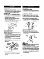
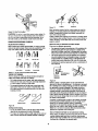
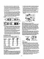
Refer to Figure 1.
Check for shippingdamage. If damage has occurred, a claim
must be filedwith carder.Check for completeness.
Immediatelyrepod:missingparts to dealer.
KNOW YOUR CUTTING TOOLS
•
Dull, gummf, improperly sharpened or set cuttingtonls can
ceuse vibrationend chatterduring cuttingoperations.
Minimize potential injuryby proper care of tools and reguier machine maintenance.
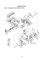
Yourwood lathe is shippedcompletein one c_ton and includes
a motor.Separate allpads from packingmaterialsand check
each one withthe unpaddnglistto make certainall items are
accountedforbeforediscardingany packingmaterial.
THINK SAFETY
If any parts am missing, do not attempt to assemble the lathe,
plug in the pawer cord,ortum the switch on untilthe missing
pads are chtained and properlyinstalled.
A
lathe
B Leg (4)
C Brace(2)
Safety is a combinationof operator common sense and alertness at all times when the lethe is being used.
•
•
•
•
•
•
•
•
•
•
•
•
For your o,,vnsafety,read all rules and pmcautioas in the
operator's manual before using thistool.
For eye protection,wear safaty glasses complyingwith
United States ANSI Z87.1.
D
E
Do net wear loose clothing,gloves, neckties, rings,
bracelets or other jewelry that ceeld gef caught in moving
parts of machine or workpieee.Wear proteotivehair covering to contain long hair.
Tighten all damps, fixtures and tailstsckbefore applying
power.Check to mak_ sure that all tools and wrenches
have been removed.
TSP(2)
Support(2)
F
12" Teel Reef
G 6"Tool Rest
H 4" Face Plate
Parts Bag (Lathe) - NOtShown
Parts Bag (Stand) - Not Shown
IMPORTANT: The bed is coatedwith a protediant.To ensure
proper fit and operation,remove coating,Coating is easily
removedwith mild solvents,such as mineralspirits, and a soft
doth. Avoidgettingcleaningsolution on paint or any of the
rubberor plasticparts, Solventsmay deterioratethese finishes. Use soap and water on paint, plasticor rubbercomponents. Wipe all parts thoroughlywith a clean dry cloth.Apply
paste wax to the bed,
With switch off, rotate workplece by hand to make sure
that there is adequate clearance. Start the machine on
lowestspeed settingto verity that the workplece is secure,
For large pieces, create a rough shape on another piece of
equipmentbefore installingon fsceplate.
Do not mount any workpleces that have splits or knots.
Remove any center from spindle when using an outboard
device for au_itiaryturning.
Ne/er attempt to remount a faneplate turningto the laceplate for any mason,
Never attemptto remounta between-centersturningit the
original centerson the turninghavebeen alteredor removad.
When remounting a between-centem turningthat has nonaltered original centers, make sure that the speed is at the
lowest settingfor etad-ap.
Use extra caution when mountinge batween.centers turning to the faceplata, or a faceplste turningto between-centers, for secondary operations. Male sure that the speed is
at the lowest settingfor start-up.
Rgum I -Unpacking
3
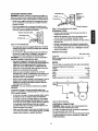
Refer to Figu="es2 - 3.
Reler to Figures 4-9,
CAUTION:
Do not attempt assembly if parts ere missing.
Use this manual to order replacement parts.
LOCATION
•
Remove all components from the shipping carton and verify
against the parts list on page 3. Clean each component and
remo_ shipping preservatives (coatings) as required.
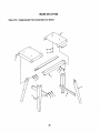
ASSEMBLE
INSTALLATION
STAND
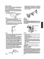
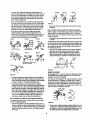
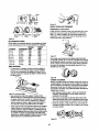
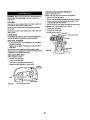
REMOVAL OF SPUR CENTER FROM SPINDLE
• To remove the spur center from the spindle, insert the center removal rod intothe spindle and gently tap the center
out. Refer to Figure 4.
Attach bracesto insideof legs usingcarriagebolts,flat washers, lech washers and hex nuts.
Turn stand upright, level standandsecure sil nuts.
•
OF CENTERS
The spur center and the bearing center have Morsetaper #1
to match the spindle and tail stockbores. To install the centers, slide them intothe bores with a firm,swift movement.
They will be further secured when a workpiece is squeezed
between the centers.
NOTE: Hand tighten all I_ nuts during stand assembly.Do
not completelytighten nuts until stand assemblyis complete.
• Piece bcth toppieces epside downee flooror benchtop.
Attach |font and rear sqoportsto topsusingthe ca,'dagebolts,
flat washers,lockwashers and hexnuts.
• Attach legs to inside nt tops usingcarriage bols, flat
washers, lock washers and hex nuts,
•
OF WOOD LATHE
The lathe shouldbe positionedsothat neither the operator
nor a casual observer is forced to stand in line with the spinning chuck.
Spur Center
Suppo_
1\
R_ure 4 - Spur Center RBmovzd
Rgum 2 - Lalhe Stand Asmmbied
REMOVAL OF BEARING CENTER FROM RAM
MOUNT LATHE TO STAND
•
NOTE: Lathe weighs apprceimately130 Ibs.Two people mw
be required for this operation,
• Obse_e Iocehend meentingholesin the stand top.Pceitinn
lathe on stand top sothat the mountingholesin the stand are
alignedwith hobs in the headstock and n_tor suppodcasting.Securelathe from underneathstand usingsed_ head
bolts andflatwashe(s.
•
To remove bearing center from tall atock quill, insert the
center remavai rod into the quill and gently tap the center
out. Refer to Figure 5.
Beanng
_r
Removal Rob
Insert 6" or 12" tool rest into holderand secure in position
with lockinghandle.
Attach speed control knQb.
When the wood lethe is reedj/for use, it shouldappear as it
doesin Figure3,
•
•
RRure 5
Inboard Spinde
POWER SOURCE
Toel ReSt
Headstock
Spinde
WARNING: Do nat connectwood lathe to the power source
until all assemply steps have been completed,
The motoris designedforoperationonthe veltageand IreqnenoJ
spedled. NotTnatloads willbe handledsafelyan voltagesnot
morethan 10% aboveor belowspecifiedvolage. Ruanklgthe
un! onvoltageswhichare notwthin rangemay causeoverheatn:j and motorburn-out.Heavy loadsrequirethat voltageat mator
terminalsbe no lessthan Ihevoltage specified on namepla_.
• Power supplyto the motoris controlledby a single polelocking rod_r switch.Rerno_ the kayin the rockerswitch to prevent unauthorizeduse.
Bed
Halide
Knob
Rgum 3 - Pmls of the Lathe
•
Examine the liee cord to male ,,_Jrethel the ping is in geed
condition and that the insulation has not been damaged
during transit.
4
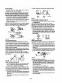
GROUNDING
INSTRUCTIONS
Qmunding Lug
WARNING:
Improper conr_dion d equipmed grounding conductor can ras.J in the dsk d electrical shod<. Eq_ment should
be grounded while in use to protect operstor from eleddcal shock.
•
Adspter_
3-Prong
Check with a qualified elestdcian if grounding instructions
are not understood or i in doubt as to whether the tool is
Ground
_A
propedy grounded.
•
M_<e Sum
This Is
__ConnectedTo
This tool is equipped with as appmvad 3*conductor cord
rated at 300V and a 3-prong grounding type plug (see Figure
6) for your protection against shock hazards.
Kqown
2-Prong Receptacle
Rgure 7 - 2-Prong Receptacle with Adapter
EXTENSION
pmpedy Grounded Outlet
Grounding Prong
CORDS
•
The use of any extension cord will cause some drop in
volnge and loss of power.
•
Wires of the _tension
cord must be ol sutficisnt
size to
carry the ourmnt and maintain adequate voltage,
3-prong Plug __
Rgum 6 - 3-1ProngRmceptado
Groundingplug shouldbe plugged directlyinto a properly
installedand grounded 3-preeg grounding-typereceptacle,
as shown (Figure 6).
• Do not ran'x_e or alter groundingprong in any manner. In
the event ot a maitunctionor breakdown,groundingprovides a path ot least resistancefor electrical shock.
WARNING: Do notpermit lingers to touch the terminalsot
plug when installingor removing lrem outlet.
• Plugmust be pluggedinto matchingoutistthatis propeby
instaled ond groundedin accordancewith al localcodas and
ordinances.Do notmodly plug provided.If itwill nO[ft in
outlet,haveproperoutletinstalledby a qual|led electrician.
• Inspect tool cords pedodicelly and if damaged, have them
repairedby an authorized seP.'iceIacitity.
• Green (or green and yellow) conductorin cord is the
groundingwire. If repairor replacement of the electric cord
or plug is necessary, do not conned the green (or green
and yellow) wire to a liveterminal.
• Where a 2-prong wall receptacle is encountered,it must be
replaced with a properly grounded :)-prongreceptacle
installed in accordancewith National Electdc Code and
local codes and ordinances.
WARNING:
electrician.
This work should be pedormed
•
Use the table to determine the minimum wire size (A.W.G.)
extension cord.
•
Use only 3-wire eadenslen cords h_iug 3-prong grounding
type plugs and 3-pob mcept asles which accept the tool plug.
•
If the extension cord is worn, cut, or damaged in any way.
replace it immediately.
Extemdon
Cord length
Wire Size A.W.G.
Up to 25 tt.....................................
MOTOR
The wood lathe is assembled
Horsepower (Maximum
with rector and wiring installed.
Developed) ...................
Voltage ...................................
1
120/240
Amperes .....................................
Hertz ........................................
Phase .....................................
RPM .......................................
814
60
Single
1725
Rotation (viewed Iron', mater shatt) .......
Counterclockwise
L1
120V I
Power
L2
1±
by e qualified
A temporary 3-preng to 2..prenggroundingadapter (see
Figure 7) is available for consentingplugsto a two pole outlet
if it is properly grounded.
Do not use a 3-preng to 2-preng groundingadaptor unless
permittedby local and national codas and ord'mances.
(A 3-prong to 2-prong groundingadapter is not permitted
in Canada,) Where permitted, the rigidgreen tab or term'lnat on the side ot the adapter must be securelyconnected
to a permanent electricalground such as a propedy
groundedwater pipe, a properlygrounded outlet b_( or a
properlygrounded wire system.
•
18
NOTE: Using extension cords over 25 It, long is not
recommended.
Rgure
B -Wiling
Green
Schemstic
ELECTRICAL CONNECTIONS
WARNING: Make sure unit is off and disconnectedfrom
power sourcebesominspectingany wiring.
The motor is installedand wiring connected as illustratedin
the widng schematic (see Figure8).
The lathe is prewiredlot use on a 120 volt,60HZ powersupply.
The powerst4)plyto the motoris controlledby a singlepole
leddng roder swich.
Many coverplate screws,water pipes and outlet bosas are
not properly grounded.To ensure proper ground,grounding
means must be tested by a qualifiedeleotrician,
5
The power lines are inserted directly ontothe switch.The
0teen groundline must remain securely fastened to the freme
to properlyprotect against electrical shock.
•
•
• Remove the key to prevent unauthorizeduse.
240 VOLT OPERATION
•
•
•
•
To use the lathe with a 240V, single-phase pov,,er supply,
have s qualified electrician attach a 240 volt. 15A 3-prong
plug Onto lathe line cord and install the proper connectors
and receptacles to power supply.
•
•
See wiring diagram (Figure 9) for wiring instructions.
•
C
3
C
__L_
C
L1
1_
_
4
240V
•
)
•
ON-OFF SWITCH
_
2
L1
Figure 9 -Wiring
2
FlesheckallIoddnghandles,Thay mustbe tightensdseoJraly.
Mak_ sure all movingparts are free and clear of any
intederence.
Mal® s_.a'e
al fastonarsam tightand have nct vbrated loose.
With power disconnected,test eperetion by hand for clearance and adjustit necessary.
Always wear eye protectionor face shield.
Alter turningswitchon, alwaysallow the spindle to come
up to lull speed before turning.
Be sure meter runscounterclockwisewhen viewing spindle
from the rightend (inboardside of headstock).
Keep handsclear of spindle,centers, faceplates and other
reeving parts of machine.
For optimum performance, do not stall motor or reduce
speed. Do not forcethe tool into the work.
Refer to Figure 19.
Power supplyto the lathe is controlledby the lockingrocker
switch.To turn lathe on:
)
• Pull red_r snitchup to the ON position.
To turn lathe _f:
• Switch off the rockersNitCh.
1.2
The rocker switch has e removable _ to prevent unsethodzBd use or accidentalstart-up of the lathe. Removingthe kay
will !ock the lathe from use.
To lock the lathe:
• Switch offthe rockerswitch.
S<d'lemallc
Refer to Figures 10 - 74.
•
•
DESCRIPTION
Craftsman 36" variable speed wood lathe providescapability
to turn woodenworkpieces up to 36' long and 4" diameter.
This lathe can also turn b_wls up to 12" diameterand 4"
thick.The motor rofstos at 1725 RPM and the spindle speeds
are 380-2150 RPM. Outboard spindle allows convenientoutboardturning of bowls up to 15" diameter.
SPECIFICATIONS
Disconnectthe line cordlram power source.
Pull out the removable key.The key has the words,
"Remove to Lock".
• Store key in a sale pla_e
NOTE: With the kay removed,the rockercan be "ROCKED",
butthe switchcannot be actuated,
To unlockthe Isthe:
•
•
•
•
Turning length (max.) ............................
38"
Bowl diareeter
(max.)............................12"
Overall
length................................. 60_
Overall
height................................. 13"
Width .......................................
15"
Inboard Spindle Speed ...............
380 to 2150 RPM
Outboard Spindle Speed ................
190-1075 RPM
SpindleTaper.................................
1MT
SpindleThreed ................................
1".-8
Tail Stock Taper ...............................
1MT
Switch ...........................
SP, Lockingrocker
Motor ..........................
120/240V, 8/4 AMPS
Weight ...................................
130 bs
Positionthe rockerin the OFF pneltinn.
Insert the key into the rocker,
Connect line cord to power source.
The switch can now be actuated.
•
WARNING: Operation of any power toolcan result in foreign
objects being thrown into the eyes, which can result in severe
eye damage. Always wear satety goggles complyingwith
Unites States ANSI Z87.1 (shown on paskage) before commencingpower tool operation.Salaty goggles ate available at
Sears retail stores or catalog.
CAUTION: Always Observethe followingsafely precautions:
Rgum 10
CHANGING
_
RemovableI_
Spindle
_/
_Roc_erSwltch
SPEEDS
To valy spindle speeds, rotatespeed control Imop to the
desiredsetting.The speed label on the headstock shows
inboardspindlespeeds in black and outboard spindle speeds
in red. Refer to speed chartfar specific turningoperations.
CAUTION: Change speeds only while motor is running.
SAFETY PRECAUTIONS
• Whenever adjustingor replacing any parts on the tool, turn
switchOFF and remove the plug from power source,
6
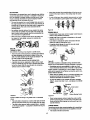
SPINDLE TURNING
•
Observe the speed chart (see page 14). For example, a 2"
square turning uP to 18" long should run at 1100 RPM for
"roughing'. Rotate the wood by hand to make sum that the
If you have never done any amount ot wood turning,we suggest that you practiceusing the variouswood turningtools.
Start with a small spindle turning.
Be sure to studythe follo_vingpages of this manuel.They
explain and illustratethe correct use at the turning tools,the
positioningot the tool rest, and other informationto help you
gain e_pedence.
• Select a plese ot wood 2" x 2" x 12".
• Draw diagonal lines on each end to locate the centers.
corners do not strike tim tool rest and verify that the indexing pin is not engaged.
Diagonal Unes on
Both Ends
Rgure 11
Rgure
•
On one end, make a saw cut epprosJn'_ely
'A," deep on
each diagonal line, This is for the spor o_nter,
•
The other end uses the bearing center. Place the point ot
the bearing center on the wood where the diagonal lines
cross`
•
14
INDEXING
Refer to Figume15,
The spinulepu[k3yhas 24 agu_Jlyspaced slots(15° apart).The
irides(
pin psssesthroughthe headstockengageswith onect the
24 slotsemdlocksthe spindle fromturningwhileyouput a mark
on thewod_lec_
Drive the bearing center into the wood. Use a wooden matlet or a plastic hammer, butput a piece of wood on the end
of the bearing center to prctect it from harm.
i Slots
Rgure lS
Rgum 12
•
•
•
•
•
•
For example, to locate the positionot six flutes on a cylinder:.
• Openthe rearcaver.
Remove the bearing center and drive the spur center into
the other end of the wood. Make sum the spurs are in the
saw cuts. Remove the spur center.
Make sure the centers and the hole in the spindle and the
tail stock ram are clean. Insert the spurcenter into the
headstock and the bearing center intothe tail atock.Tsp
them in lightlywith a piece ot wood. Do not drive them in.
II the tall stock center is not ot the ball bearing type, put a
drop of oil or wax an the wood where it contacts the center.This will It_,ricate the wood while it is tumiag.
Place the wood between the centers andlockthe t6il stock.
•
•
Movethe bearing center intothe wood by turningthe hand
wheel. Make sure that the bearing center and spur center
=seated"into the wood in the holes made eadier. Rotate
the wood by hand while turningthe hand wheel.
Adjust the tool rest approximately',_"away from the corners of the wood and %"shove the center line. Note the
angled position of the tool rest base. Lockthe tool rest
base and the tool rest.
1_
•
Pull index pin out to release pin,Slowly rotate the workpiece untilpin is located 60" (4 holes) from initial position.
Engage index pin into the pulley and place another mark
on the workpiece.
•
Continue these steps untilthere are 6 marks on the workpiece.
Bowl turnings or wheel turnings can be marked in the
S_
rn_qR eL
•
WARNING: The indexingpin must be disengagedfor all
nther operations on the lathe,
OUTBOARD
TURNING
This technique mat_s it possible to do jobs on this machine
that are too large to mount conventionally. It is straight forward
laospiste turning, except, because of the work size, caution
must be talon and speeds must be restricted to minimums. If
you anticipate doing outboard turning you must use a bowl
turning rest (see Recommended Accessories, page 27). The
bowl turning rest is attached to the lathe bed. See Figure 16,
page 8.
_'
,oo°
Rgure 13
Push index pin untilthe indexpin engages one ef the 24
slats in the spindle pulley.
Adjustthe 12" tool meatto the centerline ot the workplece
and make e mark.
TOOL REST _._
7
Rgure 19
figure
16 - Bowl Turning
CAUTION: Do not try to push this support when cutting.Do
nottry to mountwork so large that the motor must strain to
turn it. If youwish to experiment with thistechnique, do so
with softwoods. Let the heavier, herder wood come later.
CHISELS
SELECTION OF CHISELS
SKEW
PA_TfNG
"
WhenYou Can Cut andWhanYou Must Scrape
There are two ditlemnt approaches:
• One sppr_ch is towarde drcunfemsce ofthe workpiece_or
exampleturningdownthe outer surfaced a cylinderor the
innerwall d a hollowroundbex).In thisapproach,the sulfase
he k'igturnedtravelsunderthe chisel edgelikean endlessbelt.
Better chiselshave handles approximately10" longto provide
plentynt grip and leverage.Sharp tools are essentialIordean,
easy work. Select toolsthat will take and hold keen edges.
GOUGE
S
Many operationsrequirethat the cuttingchisels be used for
scraping,but scraping chisels are practicallynever used for
cutting.Scrapingdullsa chisel much faster, especiallythe
razor sharp cuttingchisels.
Cutting is faster than scrapingandproduces a smootherfinish
which requiresless sanding.However, it is far more difficultto
master.Scraping, on the other hand, is lar more precise and
easier to control.
Rest
USING WOODWORKING
Cuttin
• The secondapproachistowardthe diameterd a workpiece
(aswhen turningthe face d a fsceplate turning,or the sided
a largeshoulderon a spindleturning).In thisapproach,the
sudscebeingturnedrotatesIke a discunderthe chisel edge.
T_04_
•
Sometimesthe optirnum approachwill be a sent)ination of
both methods.
t
SPEA
fl POINT
FLATNOSE
ROUND
NOSE
Figure| 7 -The Six CommonlyUsed ChimlTypes
THEORY OF TURNING
The two classes ot chisels are those intendedpdmadly Ior
cutting,and chisels used only for scraping,
• The cuttingchisels are the gouge, skew and parting tool.
These are the most used.They are commonlysharpened
to a razor edge by honingon both sides.
• The scrapingchisels are the flat n_e, roundnose and
spear point.These are not honed on the flat sides- the
wire edges produced by grinding are felt on to aid in the
scrapingprocess.
Cutting Chisel
Diameter
Approach
Rgum 20
Either a cuttingor scrapingaction can be used when the
approach is towarda circumference- the shavingis mmaved
like a peeling from a potato.Scraping can only be used when
the approach is towarda diameter.The mason is obvious
when you considerthat faceplate turningpracticallyalways
requires removal of wood across the grain,Wood does not
peel easily acrossthe grain and attemptsto use any inappropdate cuttingmethodswill likely msul in damage to the workpiece.There is also danger that the tool couldbe pulledfrom
the hands of the operator.
In general, a cueing actionis used for the majority of spindle
turningoperations while taceplate turning is usuallyaccomplished by the scrapingmethod.When a combination
approach is to be used, the operator will haveto judge, by the
feel ot the work, when to stop cutting and start scraping.
Never try to cut when it becomes difficultto hold the chisel
against the mughnese ofthe wood grain.
Scraping Chisel
Rgum 18
Cutting and Scraping
•
To cut, the chisel is held so that the sharp edge actually
digs into the revolving work to peel otf shavings.
•
To scrape, the chisel is held at a dgN angle to the work surlace. This tool remcves fine particles instead of shavings.
Haw to PosltlonTool Rest for Clrcurnterenoa Cutting
When cutting,the object is to pierce the outer skin of wood to
a certain desireddepth and then to hold the chiselsteady
with the bevel edge parallelto the work cimundemnceso that
it will peel oft a shaving at this desired depth,
8
•
The only sure method of holdingthe chisel steady is to
mat the b_vel against the work (Figure 21A). When the toni
mat is at the proper height, the chisel can be held with the
bevel pressed against the work, and the tool restwill act
as a fulcrum to support the chisel against the downward
force of the revolvingwork.
•
Fig, 22A
• ioe
c
If the rest is placed too low, so that the chisel is held with
the bevel out from the work (Figure 21B), the cuttingedge
will continueto dig deeper intothe work. It will dig in until
the "bite" becomes so deep that your hands have difficuly
holding the chisel - then the improperlysupportedchisel
will beginto bounce or chatter against the workplace.
ffthe rest is placed ton low,the chisel must be held
extremely high to positionthe bevel against the work
(Figure 21C).Then the rest losesrno_ of itsvalue as a fulcrum and the downwardforce of the revolvingworkplecu
tends to kick the chiselback out of yourhands.
•
Fig. 21A
Rg, 21B
figure 22
•
Figure 22A shows the chisel actionwith the rest correctly
positioned.
How to PoalUon Chisel and Rest for Diameter
Scraping
When scraping on the diameter, that portico of sudase tothe
right of center is moving upward (Figure 23A). if a chisel is
placed in this area, it will simply be carrisd up oft the rest and
out of your hands.
•
Rg. 21C
All diameter approach aparations
of center,
must be done st the k_t
No aJp_xt
_ S •
'_
B_
ae_
Xhr=,
^_ml
Ctlisel
(_jn_g
Fig. 21D
.....
pl_er
Chan
_
_
_
Olbd
I_
/d"
• [
.
F_
Bev_
pelnl
R_I Too L
TOU H G'lz_m d
Fig, 21E
_I_R_
I
Handle
Three differentchiselcontactpoints are shownin Figure 23B.
It will be noted that when a chisel is above the workpieoscenter (or below it) the work sudase sweeps pastthe chisel edge
at an angle and tends to carry the chisel in one directionor
the other alongthe rest.
• Only when the chisel cent asts the work on the cehtedine,
does the work surfacepass squarely underthe chisel
edge.This, then, is the positionin which it is easiest to
hold the chisel steady.To abtain this position,place the
rest agpreximataly 'k" (thicknessof chisel)balsw center.
Kickback /i
Kickba=_.
TOO Itl_h
RI_ 21F
e
TooHi_
Fill- 2SA
FI w. 23B
Uw_
Rest Too D_IW31 * ChbalToo High
P_nl Too Fat From Rmt
Fig. 21G
R
Rgum 23
UISING THE GOUGE
Three gouges, the 'k, ',_and =k"sizes, are adequate for general hornesheptumieg, Other sizes from 'k to 2" can be purchased to provide more IleKibinty.
The chief use of the gouge is for roughcircumfarenoscutting
of raw stock down to a cylinderof worfdngsize.It is best to
use this toolfor rapidcuttingaway of large areas of the workpiece.When the tool is used thisway, it does not producea
smoothsudace,With practice,the gouge can be used for cutting covesand the shapingof long cats.
Rgure 21
If the rest is placedton high (Figure 21D) and the chisel is
correctlyposlioned tar cutting,it stdkes the workplecunear
the top where the directionof torceeKartedby the workplace
is nearly horizontal- and kickbackwill again result.
•
If the rest is placed too far out Iromthe work surface
(Figure 21E), then, when correctlyheld, the chisel is again
ton high on the work. Also, you hawetess leverage on your
side of the tool rest and it is even more difficultto hold the
chisel. With large diameter work (Figure 21F), the tool rest
can be above the workplece centedine,and sornewhal out
from the work sudace,With small diameterwork (Figure
21G), the rest shouldbe closerto the work surface.As
work grows smaller,the rest shouldbe mpositioned.
CuttingEdge
How to Po_ltlon Tool Rest for Clmunfference Soraplng
In scrapingoperations, the tool rest positionis not as critical
as it isfor cuttingoperations.
• The chisel generally is held horizontally,though it can be
held at an angle to reach intotightplaces, Considering that
the wire edge of the chisel does the scraping,Figures 22B
and 22(3 show the resultsof ton low or ton high a position
for the rest.
P_fflt
Hgum 24
•
9
When ussdfor o-tting,the gouge is alwaysheldwith the conveKside down.It should he rolledapprodmatel),30=to 45_ in
the directionin which| is beingadvancedalongthe restand
the cuttingedge should he slightlyahead ct the handle.
•
USING THE SKEW
•
Any flat sudaca can be scraped with the flat nose chisel.
Two skews, the '/z and 1" sizes, am all that are needed for
general use. Other sizes are avallsble,
This tool is nearly always used to ma_ fbished cuts, to cut vees
and beads, and to square shoulders. Properly used, i produces
the best finish that can he obtained with a chisel. It is not recommended for scraping because the edge tends to dul more qalddy.
Spear
Point
For finish cutting, the skew is held with the cutting edge
considerably in advance of the handle, bevel side down.
Keep the base ol the bevel against the work. It is good
practice is to place the skew well o_,er the wod_, pull it back
until the edge begins to cut, then owing the handle into
position to advance the cut.
Round
Nose
Flat nose
figure 27
USING SHAPER
•
OR MOULDING
KNIVES
An old chisel can be made to serve as a holder for shaper
or moulding knives.
Both the toe and the heal d the slew can be used for taking light
cuts, but do not penetrate the wood too deeply without cutting
_s.There
is danger ol burring the tip of the tooL
Such knives male it possible to scrape many interesting
shades into the workpiece surface using _
or two operations
instead of the many operations required wih standard chisels.
it is generally not practical to use cutting mathods with spedal
shape tools. Scraping methods should he used instead.
•
The holder should provide a shoulder against which the
butt end of lhe krlite can be firmly seated,The knife must
be securely mounted, either by means nt a screw threaded
into the holder, or by compressing it between two prongs
bolted together.
Rgure25
USING THE
USING A BLOCK PLANE
PARTING TOOL
The pwting tool has just one prrnaw purpose: to cut into the
workpiece as deeply as desired, or all the way through to make a
aJt-off, It is, the_ore, a very narrow tool ak" wide) and shaped to
cut its own clearance so that the edge will not he burned.When
used for scraping, however, the parting tool should be backed off
regularly to prevent overheating.
Clear, glass.smooth linishes (especially on softwoods) can be
obtained by using a block plane sat to take a fine shaving.
Unli_ the gouge and slew, the parting tool is seldom hatd with
the beval against the work. Since the _nt
of stock removal is
small, a support for the bevel is not neoes_y.
•
The tool rest should be raised up apprasimately to the top
of the workplece - and the plane should be horizontal, but
turned slightly in the direction of travel so that it will tale a
shearing cut,
•
Two tool rests, one in front and the other behind the work, can
be used to advantage in p_itioning the plane so as to eKaotly
limit the dep(h of cut (and fi_
size of the wod_piece).
The tool is simply led into the work at an angle (for cutting), or
pointed at the workpleoe center (Ior scraping). It can be held easily in one hand.
Cutting
Scraping
4--,,
Rgum 2g
USING WOOD
•
USINGTHE
•
SCRAPING
CHISELS
the rasp firmly against the tool rest. An improperly held
rasp, when used on a rough sudaoe, can kick back and
cause operalor injury,
A '/l' wide spear point chisel, a '/z"wide round nose chisel,
and a 1" wide flat nose chisel complete the list of tools
ordinarily used by crattsmen and hobbyists.
Each of these scraping chisels can be purchased in various
other sizes Ior special purposes. All am very useful for diameter scraping operations and for circumference scraping when
cutting methods cannot be employed.
•
•
RASPS AND FILES
A wood rasp will remove stock quickly when held against
the revolving workpisce. Cam should be talen to support
The spear point is used for line soraping and delicate operations such as the forming of beads, parallel grooves and
shallow vses.
Edges and bowl contours can be rounded with the round
nose chisel.
10
•
The rasp will leave avery rough finish.
•
Finer finishes (similar to those produced by scraping) can
be obtained by using files in the same manner. Various
types of files can be used for shaping vees, beads, caves,
eLc. if pressed too hard into the wood, some files can burn
the workpiece.
•
Keep the file clean to keep it cutting uniformly. Files work
best on hardwoods.
Cutting to Depth
Figure
Many scraping operations and cUtting to depth with the parting tool can be easily accomplished with the one hand. The
chisel is grasped firmly with the index finger on top to press it
down against the rest. it is thrust straight into the work.
Holding the tool in this manner leaves the other hand free to
hold a p_tem or calipers, atc., to check work in progress.
3Q - Using a Rup
HAND POSITIONS
When usingany ofthe chisels,the hand tales a naturalposition
on the toniheedl_This pssitionmav be nearthe middled the
handleor towardsthe end,dependingupan the amesnt of
leverage required.The positisnd the I'_nd nearthe ted re.stis a
matterd individualprdemnee,bUttheream threegenerally
acceptedpositions,each bestfor certaintypesd operations
%..
Rgure 84
Roughing Off
Roughingofl and other heavy work requires a firm grip and
solidpositioningof the chisel against the rest.This is best
obtainedby the toet-mat hand positionedillustrated.The wrist
is dropped down so that the heel of the hand below the little
finger acts as a slidingguide against the rest,The handle
hand controlschisel position.
Rgure
MAKING STANDARD CUTS
THE ROUGHING-OFF
CUT
Reducing a square or odd shaped workDieos down to a cylinder of approximate size for finish turning is called "roughingoff". Faosplste turnings and large diameter spindles should
first be partly reduced by sawing, but small spindles are easily
turned down entirely with the large (',_') gouge.
31 - Roughing
Finish Cutting
Finish cuttingrequires more control- with less force.Finish
cUttingis betterdone with the palm of the tool rest hand
turned up.The wrist is stillheld down, and the side ot the
index finger acts as a guide along the rest. In thispselico,
control of the chiselis shared by both hande.The lingers of
the teet-reet hand are free to assistin positioningthe tooL
RO_o
•
Figure 32 - Finilh
Start the first cut about 2" from tail stock end - then run it
towardthe tailatnekand off the end of the workpieos.
• Nsst, startanothercut 2" nearer the headstock- and run it
back towardsthe taiistnek,to merge with the first cUt.
• Continue cuttingin this manner until2 to 4" from the headstock is lett uncut.Reverse the directionof tool traveland
work one or two cUtsin successiontoward the headstock
and(_f thisend of the workpieee.
• Never start a cUtdirectlyst the end - if the chisel catches
the end, it will damage the wod_leco.
• Never take long cutswhile cornersremain on the work, as
this tends to tear long divers from the corners,
• The first series of cuts shouldnot tie ton deep. It is better
to partiallyreduce the work to a cylinderall along its
length.After that, start a second series of cutsto complete
reducingit to a cylinder.
* Once a cylinder has been Iormed, step lathe up to next
faster speed. Further reductionsin size can now he
accomplishedby cuttingas deeply as desired at any spot
along the work. At this stage, long cuts can be made from
the center to either end.
Cutting
Int deete Cutting
intricate,delicate cuttingrequireseKtremecontrolwith practically no force.This is best accomplishedby guidingthe chisel
with the fingers of the tool-resthand.The hand is held palm up
with the wrist high.The littlefinger isplaced againstthe rest to
steady the hand.The chisel does not touchthe rest andthe
handle hand is completelysecondaryto the tooFresthand.
NOTE: The first and second positionsare equally good for
scrapingoperations,hot the third position is practicallynever
used for scraping.
•
Rgure 33
11
Generally, roughingoff is continueduntilthe cylinder is
approKimately %" lan:jerthan the desired finished size.
•
Roundness can be tested by laying the gouge on top of
the work - it will not ride up and down when cylinder is
perfectly found.
Flrst Cuts
Figure 38
Testing Roundness
Figure
•
Use the gouge to remove any waste stock outside of shoulder. Smooth this section, up to within ',_" oOshoulder, in the
usual manner. Finishing at the shoulder, unless it is more
than 1" high, is best done with the q,_"sl_w.
36
ROUGH-CUTTING
TO SIZE
The toe of the skaw is used to rem_x,e the shavings from
the side of the shoulder - down to finished size.
The roughing-ooIcut can be made to accuratelysize the cylinder to a given diareeter.
Another method is to make a numberof sizing cuts at intervals alongthe work, then use the gouge to reduce the whole
cylinder down to the diameter indicatedby these cuts.
Hold skew sothe bottom edge of bevel neKtto the shoulder will be vely nearly parallel to side oOshoulder- but
with cuttingedge turned away at the top so that only the
extremB toe will do the cutting.If cuttingedge is flat
againstshoulder,the chisel will run.
Startwith handle low, and raise handle to advance toe into
the work.
MAKING SIZING CUTS
Sizing cuts am useJulto establish agprexim_e finishedsize
diameters at various points along a workpieos.The work can
then be turned down to the diameters indicated and be ready
for finishing.
Diameters for sizing cuts shouldbe planned to be about ',_"
greater than the desired finishdiameters.A sizing cut is
made with the parting toot,
• HoOdthe tool in one hand, and use the other hand to hoOd
an outsidecaliper preset to the desiredsizing-cutdiameter.
• As the cut nears completion,lower the chisel point more
and more into a scraping pnettion.
• When the calipersslip over the workoiese at the bottom oO
the groove, then the cut is linished.
•
Cut down to finished
diameter of outside area. Then, clean
out the corner by advancing heel of the skBw into it along
the surface of the outside area.
•
Tilt the cuttingedge, with handle raised up so that onlythe
extrsme heel does this cutting.
II shoulderis at end of work, the process is called aguadng
the end. In thiscase, mduse outer portionto a diameter
about '_" largerthan tool center diaree_acThen,later, saw
off the waste stock.
Figure 37
Rgure 39
CUTTING VEES
Vee groovescan be cut witheither the toe or heel of the skew.
SMOOTHING A CYLINDER
The final ',_"can be removed in two ways, Either use the 1"
skaw, workingfrom the center towardbothends and taking
lighterand lightercuts until finished,or use a block plane as
illustratedin Figure 29.
• When the toe is used,the cuttingaction is exactly the
same as when trimminga shoulderaxsspt that the skew is
tiltedto cut at the requiredbevel. Lightcuts shouldbe
taken on first one side and then the other,gradually
enlargingthe vee to the required depth andwidth.
• When the heel is used, the skmNis rotated down into the
work, usingthe rest as a pivot.Otherwise, cuttingposition
and sequence ot cuts am the same. As when usingthe
toe, it is importantthat cuttingbe done only by extreme
end of cuttingedge.
• If deep vees are planned, it is quickerto start them by
maldng a sizing cut at the center of each vee.
• Voes can also be scrapedwith the spear point chisel or a
three-sided file.
CUI"rlNG A SHOULDER
A shoulder can be the side of a squareportion left in the
workpisce,the side of a tarried section,or the end of the
workpisce.Most shouldersare perpendicularto the work axis,
but a shouldercan be at any angle.
• First, rnark positionof the shoulderwith a pencil held to
the revolvingworkpieoe.
• Second, make a sizing cut with the parting tool, placing
thiscut about '/,." outsidethe shoulderposition and cutting
to within about '/," of the depth desired for the area outside
at the shoulder.
• If shoulder is shallow, the toe of the skew can be used to
make the sizing cut.Do not go in doeper thon ',_"with the
si_w unlesswider and wider vees are cut to provide clearance for this tool.
12
•
At the start of either cut, gouge is held with handle high
and the two sides of blade held between the thumb end
fore_ingar of tool rest hand, just behind the bevel.
Position the fingers so that they are ready to roll the blade
into cove.
Roure 40
CUTTING BEADS
*
Hold bladessothst bevel is at 90° angle to the work axis
with pointtouchingthe pencil line andpointedk'itowork a_is.
• From this start, depresspoint slightlyto stad cut, then coo,
tldue to move point down in an arc towardthe bottom center cove - at the same time roilingchiseluniformlyso that,
at the end ol the cut, it will be flat at the bottom of the
cove.The object is to keep the axtrerne point of gouge
doingthe cuttingfrom start to finish. Reverse these movementsto cut the opposite side.
This operationrequires considerablepractice.
• First, make a pencil line to locate the tops (highestpoints)
of two or more adjoiningbeads,
• Then, male a yea greave st the axact center betweentwo
linesand down tothe desired depth d the separation
betweenthe beads.Be carefulnotto make the groeveton
wide or you will removepodionsof the desiredbeads.The
sidesol the two adjoiningbeads are now cut with the heel d
the sksw.Use a %"skew, unlessbeads am very la,'ge.
•
Place skew st rightangleswith the work axis,flat againstthe
sudase, andwell up near the top.The axtrerne heel should
be justit_sidethe pencil linethat marksthe topof the bead.
Now, draw slew straightback whiio raisinghandle slowlyuntil edge nt the heel at the pencil line starts to cut,
As edge begins to cut, roll sl_w in the directionol the vee
so that the _act portion of the edge which started cutting
will travel in a 90" arc down to bottom of the vea.
_R_t
Rgure
43
Coves also can be scraped to finishusingthe round nose
chisel or a rattailfile.These methods do nutgenerally produce perfectlycurvedcoves.
Upen reachingbottomd the vee,the slew shouldbe en adge.
Reverse the movementsto cut side ol the adjacent bead.
_S_ng
CUttingCoves
MAKING LONG CONVEX CUTS
•Firat, turn work downto eppraximate size, using sizingcuts
(as required)to determinevariousdiameters` Finishcuts
can then be made with either skew or gouge.
• If the slew is used, the pdncipiosof the operatlen are the
same as those employedin cuttinga bead - exceptthat
the curve is leager and may be irregular.Use the eKtreme
heel throughout- start at longer end of curve (if curve is
irregular) and progresstowardsteeper end.
• If gouge is used, make cut in the same direction.Start with
the handle well back of point- swinginghandle in the
directiondi tool travelto overtake the point, if necessary,
when the steep part of the curve is reached. Object is to
have the axtrerne point doingthe cuttingthroughoutwith
the bevel as tangent to curveas possible,
Tod
Rgure 41 - Cutting Beads
It is important that only the _treme heel should do the cuttiag.This means that the bottom edge nt the bevel naxt tothe
vea must at all times be tangent to the arc nt the bead being
lormed.
Easier beads can be shaped with the spear pointchisel.
• Use pencil marks and sizing cuts as belore.
• Push the chisel straightinto each cut end rotate horizontally to roundoff the adjacent edges. It must be moved slightly in the directionof rotation at the same time to keep the
point from digging into the adjacent bead.
Rgure 44 - Chitl
MAKfNG
Start
inclined in Direction of Cul
LONG TAPER CUTS
Long toper cuts are made UI_ long convax cuts, with the sksw
or gouge, However, the angle between the cutting edge and
hac,dle is kept constant during the entire cut.The handle is
Rnish
Rgure 42
not swung around.
CUTTING COVES (CONCAVES)
This is the m_t difficultsingle cut to master- but one of the
most important in goodwood turning.
• First, use pencil marks to indicatethe edges.
• Then, roughoutthe cave, towithinabout ',_"ct the desiredfinishedsudace,byscrapingwi_ the gougeor muadnese d'Lsel. If the ceve is to bevery wide, alziog cutscen he made to
platthe reeghingout.Once it is roughedout, the covecan he
finished in twocuts,onefrom eachsideto the bottomcenter.
•
Always cut downhill. Do nat cut too deeply at the center of
the taper.
SPINDLETURNINGS
PLOTrlNG THE SHAPE
Once the basic cutsha_'ebean mastered, you are ready to
turn outfinished work.
•
13
The first step is to prepare a plan for the proposedturning.
This can be laid out on a suitablesheet ol paper.The layout shouldbe to full size.
•
Next. prepare the turningstock by squanng it up to the
size ot the largest square or round section in your plan.
The stock can be cut to the exact length of the proposed
turning.However, in mast cases, it is best to leave the
stock a littlelong at one or both ends to allowfor trimming.
• Mount the stock in the lathe and rough it otf to a maximum-size cylinder.
•
• To make each sizing out,use outsidecalipersand set
these by actuallymeasuring the length el the vertical lines
an the paltem which representthe diameters desired.
Make the sizingcut down to the properdiameter by using
the calipersto determinewhen the cut is finished.
• Alter maidngthe sizing cuts, hang the pattern behindthe
lathe where it will serve as a guide for completionut the
workpiece.
•
Now, project your pian onto the turning bypencil marking
the various critical dimensionsalongthe length al the spin-die. These dimensionscan be laid out with an ordinary
ruler or by using a template. Make the pencil marks shout
'/z"long so they will be visible when the work is revolved
under power.The lines can be quicklytraced around the
spindle by touching each line with the pencil.
Diameters
1'_"
2" 1',_" 2'k'1_'1",_="2=,_,"
1",_'17_'1"_,'1"
I
I
_ I
1 = I
I_
SizingCuts
14'u' o
-)=.-I
Rgura
After marking, use the parting tool to make sizing cuts at
all ot the important shoulders.When
learning, you will find
it best to make sizing cuts to aocurately plot the various
dian_ters` Experienced wood workers can manage with
lewer such cuts at the important shoulders,
•
Plan each sizing cut so that it is in waste stock and make
each cut deep enough so that there will be just enough
wood left under the cut for the finishing process.
•
Once the sizing cuts have been completed, rough-out the
excess wood wiLh s gou9e. Then, proceed with the finish-
46
Using aTemplate and a Diameter Board
When many identicalturnings are to be produced, it is convenient to have a preparedtemplate.This can be made ofthin
wood or cardboard.It is outon a band saw or scrollsaw to
hove the e¢act contouror the finished turning.The number
one finished turningcan also be used as a template. Attach
the template to a boardand then mountthe board behindthe
lathe, on hinges, so that the template can be moved downto
touch the workpiace and allow you to closely dbser'.'e
progressof yourwork.
If a greatmany turningsare beingproduced,a diameter board
will savethe time usedfor resettingcalipers.Thisis simply a thin
bo_d along the edge ofwhich a oumper d semicircular cuts
havebeen preparedto representall the variouscalipersettings
requiredhx measuringthe sizingcuts.Each semi-drcalarcut is
held against thew0d<pleceinsteed ut usingthe calipers.
Rgum 45
•
Byplacingthe pattern againstthe roughed-out cylinder,you
can quicldymarkthe variouspointsut the criticaldiameters,
ing process by maldng the vadous types ut cuts required.
RECOMMENDED SPEED
Always follow recommendedspeed to do spindle turning
dependingupon the size and length of worl_iece.
SQUARE
1 to 2"
1 to2"
1 to 2"
2to4"
2 to 4"
2t04"
N' Pins
4" Plus
4" Plus
LENGTH
1 to 12"
to 24"
to 38"
1 to 12"
to 24"
to38"
1 Io12"
to 24"
to 38"
ROUGH
RPM
1300
1100
1000
1000
900
700
800
600
400
Usinga Templete
FINISH
RPM
2000
2000
2000
1800
1600
1400
1400
1100
800
Usinge Diameter Board
Rgum 47
LONG SPINDLES
A long turningcan be worked in short sections, with joints
arrangedto be at shoulderswhere they will not be noticed.
Long thin work that is likely te whip while tumthg shouldbe
supported al one or two places by a backstick.This is easy
to make. A simple backstickconsistsut a short length of
wood mountedverticallyin an emtratool rest and notched
so that it can be used to supportthe spindle from behind.
An improvedtype, which uses 2 roller =+kalewheels to form
the notch, also is shown.
DUPMCATETURNINGS
Identical turnings require great accuracy when plotting the
work and pedorming the various cuts. Many methods hove
been devised to aid in pedecting the work.
Use cA'Patterns
Prdassionsiworkersgenerallyuse a paltem or Isyoutheard.This
is a thinpleseof wood or cas:iboardupon whichis dmNns fulF
size h_ sectiond the turning.Thecontcorofthe fid...dr_d
sudase
is drawnfist. Then, the diametersat variousoriUcalpointsate
drawnto sc_e as verticallinesintersectingthe contourr.-_
14
•
Position the backstid_against a pre4umed portionnear the
center ofthe spindle,thisportionbeing at least'/+"over linish
size to allowforlater removalof any marksmade upon it.
•
Operate lathe at a slower speed than normal.Lubricatethe
workplece at point of contactwith the backstick+Use
beeswax (preferred), lard or grease.
a Morse taper shank, it can be mounted directly in some
tail stock rams. OthenNise, it can be mounted in a chuck fit-
Alter completing the turning, remove the bankstick and finish off the original point of contact. Sand off aw slight
burns remaining on workpiece,
ted with the proper type shank.
•
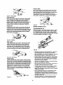
CUTTING DOWELS
Dowels of any size can be turned quicklywith the simplejig
shown.It the stock is prepa,-odas a splitor quartered turning,
half round and quarter roundswill be produced.
The jig uses a ',_"gouge as the cuttingtool and will produce
dowels sp toT,_,"diameter. Make the jig from suitable haJ'dwood stock as shown.
Figure 51
•
•
The hole throughthe jig must be large enough st the side
to the left of the gouge to allow passage of the square
stock. At the right of the gouge,this hole must be just the
diameter of the finished dowel. Make the jig so that you
can hold and guide it by hand.
• To start, center the stock like a spindle turning and turn
down about 2" at the rightend to desired size.
• Then, remove the stock. Place yourjig over the turned
end, with turned portionthroughthe smaller jig hole, and
recenterthe stock on the lathe.
•
•
Another method of holding the drill is to mount it in the
headstock using a 4-jaw (metal-lsthe) chuck or a Jacobs
chuck When this method is employed, there is no accurate
support for the workpiece so that center drilling is difficult.
Hcwover, crose drilling, or drilling random holes through
stock can be accomplished quickly in this manner.
Hold the jig firmly and start the lathe.
Push the jig slewly rightto left along the stock untilthe
whole dowel is completed.
For crossddllingfist sided work, use a (metal-lathe) drill
pad in the tail stock and place a scrapbne_dbetween the
pad and the work. For cross drillinground stock, use a
(metal-lathe) crotchcenter in the tall stock Large workpieces can be locatedon supportingblocks laid upon the
lathe bed.They can be held by band or can be supported
Irom behindby a ddllpad mounted in the tall stock.
Rgare
52 -Cross
Drilling
FACEPLATE AND CHUCK TURNINGS
Rgure
PLANNING THE WORK
Make a I;_ont first,to providea visual pattem to followwhile
workingthe turning.Pattern can be laid out in the same mannet as spindle patterns - or templates can be made which
can be held againstthe work for visual comparison.Circles to
locate the variouscritical points (st which the contoursof the
faceplate take distinctform)can be quicklysorbed on the
rotatingwork by usingthe dividers.
49
MISCELLANEOUS OPERATIONS
GUIDE BLOCKS FOR SCRAPING OPERATIOI_
A guideblock can be damped to a chisel to limitthe depth of
cut and aid in the productiond perfect _linders, tapers and
facings on leceplate turnings.Scrapingmethods most be
used when the guide block is employed.
_9_e
PLANNINGVARIOU$ CUTS
The circomi'erenceol a laceplate turning is roughed-outand
finishedin the same manner that a spindle is worked.
Practically all of the balance of the operations, however,are
done by usingscrapingmethods.A few of the standard contoura which must oftenbe tuned are illustratedin the accompanying sketchwhich also shewsthe properchisels for shaping these contours.Any roughingout to depth is generally
accomplishedwith the gouge held in the scrapingposition.
See Figure 54, page 16.
figure 50
DRILLING
There are se,reml methods of usingthe lathe for drillingcenter holes throughwood stock. When the drill is properly
mounted, centering of the hole is automatic,
• One method is to mount a ddll in the tail stock The workpiece is held and revolvedby the headstock. If the ddll has
15
Rgure
56
FANCY FACEPLATE TURNINGS
PREPARING
Round Nose
Chisel
Sposr-Pdnt
Chisel
A PLUG CHUCK
A plug chuck is an at_iliaq/wood
chuck mounted onto a faosplste. The chuck can be any size diameter, but it should be
about 1%" thick for stability. The wood chuck should be provided with a '_; or _,_" hole in the center for receiving a tenon
Measuring
Depth
turned st the end of the workpieos.
Rgure 54
RECOMMENDED
SPEED
Always follow recommended speed to do |aneplete and chuck
turning depending upon the size and thickness of workpisce.
SQUARE
4t07"
4t07"
4t07"
8to11"
8 to 11"
12to 15"
12 to 15"
12to 15"
THICKNESS
Up to2"
2 to 4"
4" Plus
Up to 2"
2to4"
4" Plus
Up to 2"
2to4"
4" Plus
ROUGH
RPM
1300
1200
1000
1000
900
700
700
550
400
FINISH
RPM
2000
2000
2000
1800
1700
1400
1200
1000
800
Rgure 57
Once made, such chucks are permanent usefulf_tures for
turningballs, goblets, etc. In use, the wood stock for tuming is
turned between centersto producea tenon at one end which
wlil be a drivingfit in the hole of the chuck,When mounted in
the chuck, the workp;aceis sobelantialiysupportedfor any
faosplste type d turning.
DEEP RECESSES
•
The first step is to mmo,_ as much wood as possible by
boring into the center with the largest wood bit available.
This can be accomplished as iliustrsi_ed in Figure 59. Be
carelul to measure in advance the depth to which ddll can
be allowed to g o.
Rgum s8
TURNING CY UNDIBRIS
Stockfor cylindersshould be mountedon the screw center or
a small laceplale.The tail stock can be broughtup to support
the work while the circunterance is being turned and finished.
Afteiwards, the tail stock is backed off and the outer end of
the cylinder is recessed, using methodsalready described |or
making deep recesses.
•
After making a recess at least ',_d the way throughthe
workpiece,and finishingthis on the inside,mmave the
workpiece from the lathe,
• Now mounta shod lengthd sdtwond stockon the screw
center andturnthisdown to |orma dowelthat will be a tight
press(not driving)fit insidethe recessedend o( the cylinder.
• Mount the cylinderon thiswonden chuck, and recess the
unworkad end deep enoughto |orm a perfect hole through
the entire cylinder.
Figure55 -_
•
Now, removethe bulk ol the waste _to rough-outthe
desired recess) by scrapingwith the round-nosechisel or
the gouge.Remove up to within 'Y" nt linishedsize in this
manner. Finish df the inside circun_emnce by scrapldg
with the spearpoint chisel or skew,Smooth the bottom o(
the recess by scraping it flat with the Ilal nose chisel.
•
pruper supportmustbe providodat ell timesfor the scraping
chisels.Severaltoolrest positionsare showninthe auccompawing illustrations.Alwaysendeavorto positionthe pad of
the rest thatsupportsthe rod as _
totheworking surface
as possible.Thedepth and squarenessd the sides d the
reoss_can be quicklycheckedby haldingoneof the straight
sidedchiselsand a combinationsquare as shown.
I
R_m Sg
16
I
RECHUCKING
•
Rechucidng is the general term used to descnbe any additional work mounting that is necessary to complete a turning projeot.The method of working ojlinders, and the use of a plug
chuck as already described are typical examples. Another
good eKample is the rechuddng of a bowl,
Alter being shucked, the remaining face of the ring can be
turned to the proper contour, thus cutting away the center
portion.
•
In work of this type, take constant measumrneats or, better
yet, use a template to guard against over or under cutting.
•
The work is mounted on a wood bac_dng block secured
the large
sudases
mounting
mounting
•
to
faceplate and it is turned in the usual manner. All
ere cut e_cept the back side (which is against the
block), The work is then removed from the
block.
•
TURNING
•
•
to complete the
2
3
4
BALLS
Wooden balls of large size are lirst roughly turned between
centers,
When the bowl is mounted in this chuck, the bottom can
be cleaned off and slightly recessed
desired contours.
1
Rgure 62
An aL_itiary chuck of softwood is now made in the same
manner that the cylinder chuck is made. This chuck must
have a turned recess properly sized to accommodate
the
rim of the bowl in a tight press fit.
using standard procedures.
Smaller balls can be mounted as taseplates on the small
facoplate
•
or screw center.
Unes drawn to indicate the center and ends of the ball
shape are helpful in plotting the curve.
•
A template should always be used for accurate visual
observation of the work progress.
Rgure 60
TURNING A RING
One method of turning a ring requires a spindle chuck,
•
The work stock is first mounted to a bacldng block held by
the large taceplste and is turned to shape on the outer
side. The inside diameter of the ring is also shaped - all
the way through to the bacldng block.
•
The work is then removed from the backing block.
•
A spindle chuck is now prepared so that it will be a tight
press to fit inside the ring.The ring is raversed and mounted on this chuck. With the ring mounted, the remaining
contours can be turned to shape.
Figure64
If the ballis mountedas a facoplateturning,almost the entire
surfacecan be turnedbeforeit becomescecessaryto rechuckit.
Flechuddngcan be be accemplishodin a dsepcupchuck
whichwill holdthe tirishedportionof the ballin s tightprosetit.
Another method of reshuddngis to use a shallow cupchuck
whichwill not supportthe ball alone, but must be used in conjunctionwiththe tall stock,
• When usingthe shallowchuck, a wsed blockis fitted to the
tail stock sothat the ball can revolveupon it. This block
shouldbe lubricatedwith bees'vax or grease.
• In usingthe shallONchuck method, the ball is constantly
shifted- never more than ',_turn - and alwaysin a definite
pattern.
Woodblod(
B.B.
Center
Rgure el
Rgure 64
Another method of turning a ring makes use of a recessed
chuck,
•
•
The work stock is mounted ne a sorew center and oce heit of
the ring is |ormed, but the ring is not cut away from is center.
•
The stock is then removed, and a mcesssd chuck - mounted
on the large facaplete - is prepared to receive the ring in a
tight press tit.
Shallow Beadng Center
Since turningbstween senters makes the work a periect
sphereacross the grain,the ball must be mountedin the
chuckso that the first scrapingcuts will round it up in the
oppositedirection.
TURNED
BOXES
Turned boKes irlvoive deep reses_ng together with a special system of working the lid and body of the boKtogether as one unit.
•
17
The inside of the lid is turned first.
•
Next, the inside of the body is turned. A care/ul check must
be made when turning the lip of the body podiorl so that
the lid will be a tight press fit.
•
The lid is then pressed onto the body and the outer circumference and face of the lid, together with the outer drcumference
of the body, are turned all at one tk_e.This insures accurate
matching of the two pieces.
•
After the work is complete, the tight fit nt the lid can be
relieved by sanding the lip of the body.
Rgure 67
TURNING
TYPES OF PLASTICS
There are two general groups of plastics.The first includesall
phenolplastics mnided underheat and pressure. Bakeliteand
Formica are examples. In the second am all catalystsetting
plasticsef variousbases sold undersuch trade names as
Lucite,Cetalin, Cast Bakelite, Marbiette,Tenite andTraltord.
Those in the secondgroup are most generally used for creft
work.They are easy to turn, being a Iffiie harder than wood,
but much salter than are/of the soft metals.
BadgingBlock
Route 65
SEGMENTED
MOUNTING THE WORK
The most useful mountingdevice is the 4-jaw (metal lathe)
chuck. When thisis not available,cylinders can be mounted
on a slightlytapered wooden mandrel. Reds can be mounted
between centers, usingeither the wood mountingcenters or
metal mountingarrangements.When the spur center is used,
slotsshouldbe sawed acrossthe work.
TURNINGS
Segrnehted bowls and boKes are exceptionally attractive- and
this method of preparing wood stock is more economical than
the use d a large piece of stock. Far some typos of work, segmeriting is the only practical method because a block (f obtainable) would be so laKje that it would be very lilely to warp.
•
The bowl illuetrsted in Figure 66 requires 12 segrnont pieses
lot"the sides. Bowls can also be worked with 6 or 8 pieces.
•
USE OFWOODTURNING
To make the 12-piece bowl, a board about _/,x 3 x 30" is
cut into pieces about 2'/," long, the saw blade being tilted
15 = and the board being turned altemetely lace up and
face down to make the successive cuts.
•
These 12 pieces am glued together and clamped by wrapping the assembly with wire (or equivalent).
•
When dry, the rim thus Iormed is glued to a temporary cir-
PLASTICS
CHISELS
Standard wood turning chisels are excellent for turning piestics by means of scraping methods.
•
The tool rest should be slightly below center and the chisel
handle should be held a little higher than the cutting edge
to give a negative rake.
•
Scraping tools should be kept to a minimum. A large contact area, such as the lull edge of the epear-polnt chisel,
will cause chatter and probable chipping.
•
Properly worked, the chip comes off in a continuous rbbon.
•
In cetd weather, plastic may hecome brittle and shsold be
tempered in warm water for about ton minutes before turning.
cular b ad,,,ingwhich is mounted on a large laceplate.
Rgure e6
•
•
•
•
•
•
A "/," deep recess of the largestpossible diameteris
turned in the open end of the rim.
The rim is removedfrom the lethe and stock forthe bottom
is mounted in its place on a second laceplete. This is
turned to size - and a rim about '/," deep is turned to
exactly fit the recess prepared in the rim.
The dm is then fitted over the bottom andglued, making a
drum shepe with a faceplate st each end,
This drum is cut cee'plately in two at a point about =,_"
above the bottom - completingthe cut with a hand saw.
Bothparts of the cut surface are faced offsquare and
smooth- then reglued together,breakingthe jointsexactly
hall and hall The cuttingand regluingprocessis repeated
with a section about 1'/*"wide.
Rgure 68
USE OF FORMEDTOOLS FOR PRODUCTION BEADING
AND SIMILAR OPERATIONS
When a number of identicalpieces are to be produced,all
having a distinctivesurfacepettem, pre/ormed toolswill
speed the work and assure unilorm_y.Pettems likethose
illustratedcan be created by grindingthin (.020 to .01(7')
gauge aluminum strips.A holder,likethe one shown,can
then be used to support any of your prepared stripsand to
guideit against the workpiece.See Figure 69, page 19.
Alter this, the temporanj backlogblock is cut oft, leaving
the bowl as shown in the linal illustretion.From this point
on, the work is simply a matter of turningdown the bowl to
any desired shape.
18
Rgure
69
WoodFibers
TURNING BALLS
r@
Plastic balls are rough turned in the usual manner and then
broughtto perfect roundnessby using a tube tool,The tube
shouldbe slightlyless in diameterthan the finished size of
the ball. It can be brass or steel, ground square acrossthe
end. The tool is used with or without a rest, and is worked by
swingingit from side to side.
Sandpaper
J®
Fibers tilted aridCut Off
Figure 70
R0are 72
POLISHING PLASTICS
OF BANDING DRUMS
Refer to Figure 73.
Standard sanding drums are usuallyrubber cylinderswhich
can be expandedto hold an abrasive sleeve in place. Similar
cylinders, turned on the lathe and covered with abrasive
paper, will be adequete for the job.These have the advantage
thst special sizes, lagers, etc. can be made. Adhesivepapers
must be glued to the cylindrical surfaceprecisely and completely.
Start with sanding.
• First use 150-grit dry paper to removetool marks.
• Then finishoffwith 150-grit and 400-grit papers, in succession. These abrasives should be wet.
•
Press lightlyto avoid overheating and marringthe work.
•
Buffinggives the fklai polish,usingthe polishingcompounds
commonlysuppliedforthispurpose.Do notpresstoo hardor
holdthe wheel at one spot too long- keep movingaroundotherwise the plasticmightbecome heat marled.
SANDING,
BUFFING
AND POLISHING
USINGTHE LATHETO SANDTURNINGS
• Turalngs shouldbe sanded with the Isthe runningin second I(_Nestspeed.
•
•
Rgure 73
A large sheet of sandpaperis usefulfor smoothingcylinders,
All other sanding operations are done with a narrowstrip
oi abrasive paper. The best finishinggri is 3/0 for softwood, 4/0 for hardwoods.Worn 2/0 paper is oftenused,
and is the equivalent of 3/0 or 4/0 new paper.
The drum is usedmainlyfor sandingthe edges oi curvedwork.
• The squarenessof the edge of the work can be best
retainedby usinga simpleform of vertical fence _ shown.
• The standard sandingdrums are commonly made with a
threaded hole to fit the lethe drive spindle.
• To guard against leeeen_g of the taper shankwhile the
drum is in operation,it is advisableto supportthe free end,
usingeither a baibearing or plain 60'=centerin the tail stock.
Rgure 71
USE OFWOOD
The aopicatianof the sandpaperstrip is shownin the ilustretians.
•
CHUCKS
FOR SANDING
Quick-acting chucks can be very useful for sanding operations
on doplicate production pads. The chuck is made slightly
cversized, and a piece oi rubber hose (for small parts) is
Care must be exercised in order to pr_ent dubbingthe
cornersof beads, shoulders, etc.
inserted in the recess to grip the workpieoss.
J
19
REPLACING
WORN VARIABLE
SPEED
BELT
Refer to Figures 76 and 77.
NOTE: Snap ring pliers are required for this operation.
WARNING: Make certainthat the unitis disconnectedfrom
power sourcebefore attemptingto service or remove any
component.
•
Remove rear cover (4 screws).
•
Ren'Kx,e outboard spindle assembly and drive bet (3 screws).
Remove snap ring, outboard spindle drive puller, and stationary apindie pulley from spindle.
CLEANING
Keep machine and wort_shepdean, Do not ailow sawdust to
accumulate on the tool, Keep centers clean.
Remove snap ring, cap, apdng and pulley from drive shaft.
CAUTION:
Be certain motor is kept clean and is frequentlyvacuumed
line of dust.
•
•
Use soap and water to clean painted parts, rubberparts and
plasticguards.
Assemble in reverse order.
Outboard Spinde Assembly
LUBRICATION
The shieldedball beadngs in thistool are permanently lubricated at the factow.They require no further lubricefine.
KEEP
TOOL
IN REPAIR
•
If pcwer cord is worn, cut, or damaged
replaced immediately.
-
Replace any damaged or missing parts. Use parts list to
order parts.
in any way, hove it
Any attempt to repair motor may create a hazard unless
repair is done by a quaiified service technician. Repair service
is available at your nearest Sears atom.
Figure 78
REPLACING DRNE BELT
Refer to Figures 75 and 77.
•
Remove cover (3 screws)
Loosensocket head boit.
Push motor towardsbed and remove belL,
•
Replace belt and assen_)le in roversoorder.
Socket
S
Screw
Mat_ r pulley
Rgure 75
Cap is spring loaded and in tension.
Remove and replace belt.
Bed Transmission Pulley
20
SYMPTOM
otorwili not start
POSSIBLE CAUSE(S)
1. Lowvoltage
CORRECTIVE ACTION
1. Checkpowerlineforpropervoltage
2. Openconnections.Circuit
in motoror loose
Inspect all lead connectionson motor I
2. Ior loose ar open connection
i
lMotor will not start; fuses blown or circuit
3. Defective capacitor
1. Short circuit in line cord or plug
3, Replace capacitor
-1. Inspect line cord or plug for damaged I
breakers are tripped
2. Short circuit in motoror loose
connections
2. Inspect
all leadshortedwires
connectionson motor J
insulationand
I
or oose or shorted termioas or
worn insulationon wires
]
3. Install correct luses or circuitbreakers
3. Incorrectluses or drcuit breakers
in po_er line
Motorfalls to developfull power (power
outpUtot motor decreases rapidlywith
decrease nvoltage at motortennnals)
1. Power line overloadedwith lights.
appliances and other motors
2. Underefze wires or circuitstou long
1. Reduce the load on the power line
3. General evedoading of power
company'sfacilities
2. Increase wire sizes or reducelength
ot wiring
3. Request a voltage check from the
power company
Motor(_verheats
Motor overloaded
Reduce load on motor
Motorstalls (resultingin blown fuses or
_dppedcircuit bma_rs
1. Short circuitin motoror loose
connections
1. Inspect connections in motor for
loose or shorted terminals or
worn insulation an lead wires
2. Low voltage
3, Incorrectfuses or circuitbreakers
in power line
4. Motor overloaded
2. Correct the low line voltage cendition_
3. Install correct fuses or circuit breal_rs
1. Applying too much pressure
piece
1. Ease up on pressure
I
Vlachine slows down while operating
Tool "chatters" dudng turning operation
to work
4. Reduce load on motor
2. Motor drive belt loose
2. Reposition motor to add tension to
drive belt
1. Workpiece
1 True up the roundnessof the
workplecebefore tuming operation
2. Establishnew center rnerl_ on ends
to reducewobble
3. Read instructionsandtake lightercuts
to minimizechatter
4. Use cutting motionthat is with
the grain
5, Install a steady rest in the middle,
behindthe workpiece
is too far out-of-round
2, Workpieco has too muchwobble
3. Operator usingbad technique
4. CUtting motionis againstthe grainot
the warkpiece
5. Workpiece is too long and
thin- workpleceis dollected
byrod pressure
Workpieco splits or "breaks up" during
tumin9 o_)erat!on.....
i
Workpiece
_mounting
contained defects before
...............
21
Select or assemblea workpiecothat is
f_me
of d3,f_e=_
..............
NOTES
22
NOTES
23
Model 351.217120
Figure 77 - Replacement
Parts
Illustration
for Lathe
8
13.
,53
11.
38
_89
94
24
rKEY
_K_:Y
I NO.
PART NO.
'18120.00
2
STD315555
3
4
18121.00
18122.00
5
01900.00
18123.00
6
DESCRIPTION
QTY
Outboard Spindle
I 1
6005zz Bal Bearing"
; 3BMI-47 Retaining Ring
! 4
', 4
NO.
50
51
PART NO.
18151.00
01930.00
52
53
18152.00
18153.00
Spindle Seat
I
3AMI-25 Retaining Ring
OUtboard Spindle Pulley
Drive Belt
3
1
1
54
18154.00
55
18155.00
56
18156.00
7
i18124.oo
8
9
[30256.00
00483.00
3AMI-20 Retaining Ring
8-1.25 x 25ram Socket Head Bolt
1
8
57
58
01282.00
01874.00
10
STD852008
8mm Lock Washer*
8
59
16080.00
11
00341.00
3AMI-17
1
60
00389.00
12
181 25.00
Outboard
1
61
18157.00
13
14
18126.00
Stationary Spindle Pulley
1
62
01680.00
18127.00
Variable
I
63
18158,00
15
16
18128.00
18129.00
Movable Spindle
51106 Beadng
1
64
65
18060.00
18159.00
17
18
16453.00
01097.00
6-1,0 x 40ram Socket Head Bolt
6-1.0 x 35mm Socket Head Bolt
66
67
18160.00
18161.00
19
Pla_e
68
18162.00
21
i 18130.00
i 181 31.00
18132.00
23
18133.00
181 34.00
24
25
18135.00
181 36.00
L_
00961.00
27
28
i
Retaining Ring
Spindle Drive Pulley
Speed Bell
Pulley
Plate
2
69
18163,00
Spacer
Unk
4
1
Nut (LH)
1
70
71
72
18164.00
STD851008
00732.00
73
74
18165.00
18166.00
75
18167.00
18168.00
00067.00
I
32
i:
135
Adjusting
Screw
1
Nut (RH)
6-1.0mm Hex Nut
1
5
01760.00
18137.00
6-1.0 x 16ram Socket Head Bolt
3
Adjusting Plate
1
76
77
181 38.00
05479.00
Bushing
6-I.0 x 16ram Pan Head Scm,v
1
4
78
79
18169.00
18170.00
181 39.00
Headstock
1
80
9-25356
181 40.00
18141.00
Cap
1
81
20059.00
Spdng Retainer
Spdng
Pin
1
1
1
82
18172.00
83
84
18173.00
118174.00
18142.00
181 43.00
181 44.00
Cover
Movable Transmission Pulley
1
85
18175,00
20063.00
01043.00
Stationary Transmission Pulley
6-1.0 x 8ram Set Screw
1
3
86
87
18176.00
18177.00
STD31 5225
06410.00
6202zz Bail Bearing*
8-1.25 x 16r_"n Socl=_ Head Bolt
2
3
88
89
18178.00
18179.00
41
42
20064.00
18147.00
Beating Support
Headstock
Body
1
1
90
91
18180.00
18181.00
I 43
18148.00
Index Pin with Chain
1
92
08637.00
I 44
02472.00
9-22554
08335.00
1
3
93
45
5 x 5x 35ram Key
5 x 5 x 18ram K_=y
94
18183.00
Spindle
1
1
18193.00
20057.00
2
20058.00
1
20060.00
46
181 49.00
47
181 50.00
/ Transmission
i01784.00
I 5..O.8 x lOmm Pan Head Screw
[ 48
_4,9
[STD851005
Sbait
_ 5mm Flat Wm&he('
*
Standard hardware item available locally
&
Net Shown
18184.02
25
DESCRIPTION
QTY.
Knob
4-O.7 x 6mm Pan Heed Screw I 1
' Pointer
1
Rack Cover
1
Rack
Guide
k 11
Bushing
6-1.25 x 6ram Set Screw
6-1,0 x 20mm Pan PleadScrew
2
I1
12
Switch w_h Key
5,0,8 x 12mm Pan Head Screw
Switch Box
Strain Relief
Switch Plate
5-0.8 x 10mmTap Screw
Bed Tube Assembly
Tool Rest Bracket
Pin
Locking Handle
Tool Rest Support
Tool Rest Holder
8mm FIstWasher'*
8-1.25 x 30ram SockatHead Bolt
12" Tool Rest
MotorCord
Motor
Grommet
Line Cord
Handwheel
Quill
#1M'F Bearing Center
TailstockBody
LockingHandle
Collar
Motor Support
Motor Pulley
TransmissionShett Pulley
V-beit
Cover
Center Cup Insert
Spur Center
Cap
6006ZZ Ball Beadng
4,"Faceplste
6" Tool Rest
Center Removal Rod
Threaded Bushing
Bushing
LockingHandle
OperstoCsManual
1
7
1
1
1
3
1
1
1
3
1
1
4
4
1
1
1
1
1
1
1
1
1
1
1
1
1
1
1!
1
1
1
1
1
1
1
Model 351.217120
Figure 78 - Replacement
Parts Illustrat|on
for Stand
26
KEY
NO.
1
2
3
4
5
6
7
PART NO.
18185.00
STD533107
18186.00
18187.00
STD551031
STD551131
STD541031
DESCRIPTION
Top
"/,o-18x °,_"Carriage
Leg
Brace
_A,"Flat Washer*
'A," Lock Washer*
',_," Hex Nut*
8
9
10
18188.00
06410.00
STD851008
Support
8-1.25 x 16mm Socket Head Bolt
8ram Flat Washer*
18189,00
18190.00
4" Outboard Faceptata
8" Outboard Faceplate
A
&
&
Standard hardware item available locally
Not Shown
RECOMMENDED
ACCESSORIES
i A-TM'I'I Work Arbor with Jaccbs Chuck
A
A
A
_.
A
_.
A
/,
/,
,_
&
M'I'I
MT1
MT1
MT!
MTt
WorkArborwithFlanges
60 ° Bearing Center
Spur Center
60 = Center
Screw Center
MT1 TallstockCup Center
4" Face Plate, t"-8 TPI
8" Face Plate, 1"-8 TPI
6'/z"x 4-Jaw Chuck, t"-STPI
Center Finder
RQbert SofoyTurningTools (6 pc. set)
9-25354
9-25355
925356
9-25357
9-25358
9-25359
9-25360
9-29840
9-29841
9-29842
9-25372
9-2983O
Accessories available in catalog and largerretail st(ca,s.
27
Bolt*
QTY.
T 2
40
4
2
40
40
40
2
4
4
Your Home
For repair-in your home-of
all major brand appliances,
lawn and garden equipment, or heating and cooling systems,
no matter who made it, no matter who sold it!
For the replacement parts, accessories and
owner's manuals that you need to do-it-yourself
For Sears professional installation of home appliances
and items like garage door openers and water heaters
1-800-4-MY-HOME
Call anytime,
® (1-800-469-4663)
day or night (U.S.A. and Canada)
www.seam.com
www.sears.ca
Our Home
For repair of carry-in items like vacuums, lawn equipment,
and electronics, call or go on-line for the location of your nearest
Sears Parts & Repair Center.
1-800-488-1222
Call anytime, day or night (U SA
only)
www.seQrs.com
To purchase a pmtecl_onagreement on a product serviced by Seam:
1-800-827-6655
(u.s.A.)
Para pedir servicio de reparaci0n
a domicilio, y para ordenar piezas:
1-888-SU-HOGAR
_
!
1-800-361-6665
Au Canada
(Canada)
pour service en frangais:
1-800-LE-FOYEFP
c
(1-eoo-533-6937)
(1-888-784-6427)
www .sears .ca
sm 8
® Regtsteced Trsdema#, / ra Trademmk / aM SOP'i= Miuk Cf Seam, Roebuck and Co.
® M area Regist rada / TMMsrca de Fr4bdca / su Mares de 5ent;cio de Sears, _ck
md _
MCMarque de cornmeme / MDM arqJe ddpo,s_e de Sem_ Roebuck md Co.
@ Seam, Roebuck end Co