1
MARINE DIESEL
OWNER'S MANUAL
MODELS
M2-12 M3-20 M4-30 M-2SXP
M-35 M-30 M-40 M-50
M~2
M~5
M~8
M~O
M~5
PART NUMBER
200157
~r-.v- 'WESTERBEKE
j
WESTERBEKECORPORATION
MYLES STANDISH INDUSTRIAL PARK
150 JOHN HANCOCK ROAD, TAUNTON, MA 02780-7319
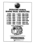
MARINE DIESEL
OWNER'S MANUAL
MODELS
M2-12 M3-20 M4-30 M-2SXP
M-35 M-30 M-40 M-50
M~2
M~5
M~8
M~O
M~5
PART NUMBER
200157
~r-.v- 'WESTERBEKE
j
WESTERBEKECORPORATION
MYLES STANDISH INDUSTRIAL PARK
150 JOHN HANCOCK ROAD, TAUNTON, MA 02780-7319
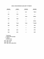
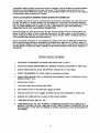
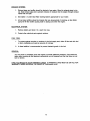
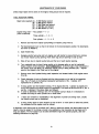
MODEL CROSS REFERENCE GUIDE (PAST 10 PRESENT)
ORIGINAL
UPDATE
5411
5416
1987-1988
1988-1989
M-12
***M2-12
**M-18
#M3-20
*M-15
*M-20
#M4-30
5421
**M-25
5424
M-30
**M-25
***M-25XP
M-30
M-35
5432
M-40
M-40
5444
M-50
M-SO
* Discontinued
** Replaced With New Model
*** Improved
# New Mini Series
New In 1986 - M-25XP
New In 1987 - M-35
New In 1988 - M2-12, M3-20, M4-30
PAGE
CONTENTS
Table of Contents ............................................................. .
3
Caution ..................................................................... .
4-5
General Information ........................................................... .
6-7
Preparations For Starting ....................................................... .
7-8
Before Starting ............................................................... .
8
Starting Engine .............................................................. .
9 - 10
Engine Break-in and General Running ............................................ .
10
Stopping the Engine .......................................................... .
10
Decompression Lever ......................................................... .
11
Instrument Panel ............................................................. .
11 - 12
Wiring Diagram. . . .. . . . . . . . . . . . . . . . . . .. . .. . . . .. . . . . . . . . . . ... . . . .. . ... . . . . . . . ..
13-
Preparing Engine for Storage. . . . . . . . . . . . . . . . . . . . . . . . . . . . . . . . . . . . . . . . . . . . . . . . . . ..
14 - 16
Preparing Engine for Spring Service . . . . . . . . . . . . . . . . . . . . . . . . . . . . . . . . . . . . . . . . . . . . . .
17 - 18
Maintenance of Engine . . . . . . . . . . . . . . . . . . . . . . . . . . . . . . . . . . . . . . . . . . . . . . . . . . . . . . . . .
19
Diesel Valve Timing. . . . . . . . . . . . . . . . . . . . . . . . . . . . . . . . . . . . . . . . . . . . . . . . . . . . . . . . . . . .
20
Adjusting Fuel Timing . . . . . . . . . . . . . . . . . . . . . . . . . . . . . . . . . . . . . . . . . . . . . . . . . . . . . . . . ..
20 - 21
Decompression Device Adjustment. . . . . . . . . . . . . . . . . . . . . . . . . . . . . . . . . . . . . . . . . . . .. . .. 21 - 22
Fuel System. . . . . . . . . . . . . . . . . . . . . . . . . . . . . . . . . . . . . . . . . . . . . . . . . . . . . . . . . . . . . . . . ..
22 - 23
Fuel Bleeding. . . . . . . . . . . . . . . . . . . . . . . . . . . . . . . . . . . . . . . . . . . . . . . . . . . . . . . . . . . . . . . ..
24 - 25
Oil Filter Change . . . . . . . . . . . . . . . . . . . . . . . . . . . . . . . . . . . . . . . . . . . . . . . . . . . . . . . . . . . . ..
25 - 26
Sea Water Pump and Impeller Replacement. . . . . . . . . . . . . . . . . . . . . . . . . . . . . . . . . . . . . . ..
26 - 2:1
Pump Impeller and Parts Diagram. . . . . . . . . . . . . . . . . . . . . . . . . . . . . . . . . . . . . . . . . . . . . . ..
2:1 - 30
Model 15 Sea Water Circulation Diagram ..... : . . . . . . . . . . . . . . . . . . . . . . . . . . . . . . . . . . . .. 31 - 32
Model 12, 18, 20, 25, 25Xp, 30, 40 & 50 Water
Fresh Water Circulation Diagram . . . . . . . . . . . . . . . . . . . . . . . . . . . . . . . . . . . . . . . . . . . . . . . ..
33 - 34
Hurth Transmission . . . . . . . . . . . . . . . . . . . . . . . . . . . . . . . . . . . . . . . . . . . . . . . . . . . . . . . . . . ..
35 - 40
Periodic Service Chart for Engine. . . . . . . . . . . . . . . . . . . . . . . . . . . . . . . . . . . . . . . . . . . . . . . . .
41
Marine Engine Warranty - Limited . . . . . . . . . . . . . . . . . . . . . . . . . . . . . . . . . . . . . . . . . . . . . . ..
42 - 43
Engine Specifications . . . . . . . . . . . . . . . . . . . . . . . . . . . . . . . . . . . . . . . . . . . . . . . . . . . . . . . . ..
44 - 69
FILL OUT AND MAIL YOUR WARRANTY CARD NOW!!
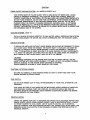
CAUTION
Your Universal Diesel engine is supplied with top quality, factory tested components. These will not,
however, replace safe practices in the handling of fuel and the use of your engine. The following procedures, if observed, will help insure safe operation and prevent damage to your engine and its
components.
SAFETY PROCEDURES:
KEEP THE ENGINE AND ENGINE COMPARTMENT CLEAN AND FREE FROM OILY WASTE
AND CLOTHS.
KEEP FUEL AND OIL OUT OF BILGE.
PERIODICALLY INSPECT THE ENGINE, EXHAUST SYSTEM, FUEL LINES AND WATER CONNECTIONS FOR LEAKS.
DO NOT OVERFILL THE FUEL SUPPLY TANK, THIS MAY CAUSE RAW FUEL TO ACCUMULATE IN THE BILGE.
THE BLOWER SHOULD ALWAYS BE OPERATED FOR APPROXIMATELY FOUR (4) MINUTES
PRIOR TO STARTING THE ENGINE SO THAT THE ENGINE COMPARTMENT WILL BE COMPLETELY VENTILATED, IF BLOWER IS INSTALLED.
LUBRICATION:
THE ENGINE IS SHIPPED FROM THE FACTORY WITH THE CRANKCASE EMPTY.
THE CORRECT GRADE AND AMOUNT OF OIL MUST BE ADDED BEFORE OPERATION, SEE
SPECIFICATIONS AND FILL TO FULL MARK ON DIPSTICK.
THE TRANSMISSION IS FILLED BEFORE SHIPMENT BUT THE OIL LEVEL MUST BE CHECKED BEFORE OPERATION, SEE SPECIFICATIONS, PAGE 41.
ALTERNATOR:
TO PREVENT ALTERNATOR DAMAGE, DO NOT OPEN OR SWITCH BATTERY CIRCUITS
WHILE THE ENGINE IS RUNNING.
RACING THE ENGINE:
DO NOT RACE THE ENGINE. THIS PRACTICE MAY CAUSE SERIOUS DAMAGE.
DECOMPRESSION LEVER:
DO NOT USE THE DECOMPRESSION LEVER TO STOP THE ENGINE, THIS WILL CAUSE
SERIOUS DAMAGE TO THE EXHAUST VALVES. MODELS M-12, M2-10, M3-20, M4-30 ANd M-3S
DO NOT HAVE A DECOMPRESSION LEVER.
MAINTENANCE AND UPKEEP:
IT IS THE OWNER'S OR OPERATOR'S RESPONSIBILITY TO PERFORM ALL NECESSARY
PREVENTIVE MAINTENANCE AND UPKEEp, AT LEAST SEMI ANNUALLY.
4
-CAUTIONFRESH WATER COOLING SYSTEM: ALL MODELS EXCEPT M-15.
THIS SYSTEM MUST BE FILLED SLOWLY WITH A SOISO BLEND OF WATER AND A GOOD
GRADE OF PREMIUM ANTIFREEZE. (THE COOLANT BLEND MAY CHANGE, BASED ON
CLIMATIC CONDITION IN YOUR AREA.) OR YOU MAY ALSO USE CLEAN FRESH WATER WITH
AN ANTI RUST INHIBITOR. DO NOT USE PURE ANTIFREEZE. AFTER ENGINE HAS REACHED
OPERATING TEMPERATURE IT MAY REQUIRE ADDING MORE COOLANT AS THE AIR IS
PURGED FROM THE SYSTEM. IF ENGINE OVERHEATS, RECHECK LEVEL, IF HOT WATER
HEATER IS INSTALLED, ALL AIR MUST BE REMOVED FROM THE LINES AND SYSTEM TO
PREVENT OVERHEATING USUALLY BY MEANS OF AN ADDED BLEED VALVE IN HEATER LINE
OR EXPANSION TANK IN THE SYSTEM.
COOLING SYSTEM: Model 15
THE M-15 WHICH IS COOLED DIRECTLY BY SEA WATER, USES A RECIRCULATING SYSTEM
WHICH DISCHARGES THE WATER AND VAPOR OVERBOARD WITH THE EXHAUST GASES.
EXHAUST SYSTEM:
IT SHOULD BE INSTALLED WITHOUT SHARP BENDS AND SHOULD BE DESIGNED TO DRAIN
ANY WATER AWAY FROM THE ENGINE. THE WATER INLET TO EXHAUST LINE MUST BE
LOCATED TO PREVENT WATER FROM BACKING UP INTO THE ENGINE.lF A WATER-LIFT
"CAN" TYPE MUFFLER IS USED, BE SURE IT IS LARGE ENOUGH TO HOLD APPROXIMATELY 3 TIMES THE AMOUNT OF WATER THAT MAY BE IN THE LINES WHEN THE ENGINE IS
SHUT DOWN SO THAT WATER WON'T BACK UP INTO THE ENGINE.
CAUTION
PROLONGED CRANKING OF THE ENGINE WITH FAILURE TO START CAN FILL THE EXHAUST SYSTEM WITH SEA WATER CAUSING IT TO BACK UP INTO THE ENGINE CAUSING
SERIOUS DAMAGE TO THE ENGINE WHEN CRANKING IS STOPPED.
CHECK COMPLETE SYSTEM AT LEAST MONTHLY FOR LEAKS.
STARTING & STOPPING ENGINE:
BE SURE TO CAREFULLY READ INSTRUCTIONS ON HOW TO START AND STOP YOUR
ENGINE BEFORE STARTING ENGINE.
FUEL SUPPLY:
DO NOT RUN ENGINE OUT OF FUEL OR RE-BLEEDIN.G OF YOUR FUEL SYSTEM WILL BE
REQUIRED.
FUEL MUST BE FREE OF ANY MOISTURE OR IMPURITIES. CHECK CAREFULLY. MOISTURE
CAN SERIOUSLY DAMAGE PUMP AND NOZZLES. AN ADDITIVE SHOULD BE USED AS
BACTERIA GROWTH CAN PREVENT GOOD RUNNING CONDITIONS CAUSING THE ENGINE
TO RUN ERRATIC OR LOSE POWER.
STARTING MOTOR:
CRANK THE ENGINE FOR ONLY 10 SECONDS AND PAUSE FOR 10 SECONDS. REPEAT UNTIL
ENGINE STARTS. NEVER CRANK ENGINE LONGER THAN 20 SECONDS WITHOUT A PAUSE
TO PERMIT STARTER TO COOL DOWN. USE OF GLOW PLUGS WILL AID IN STARTING,
REDUCE CRANKING TIME AND INCREASE BATTERY LIFE. ENGINE SOLD AFTER EARLY 1983
REQUIRES GLOW PLUG BUTTON TO BE ENGAGED IN ORDER FOR STARTER BUTTON TO
ENERGIZE STARTER.
5
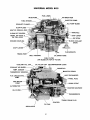
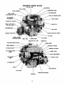
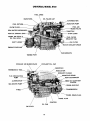
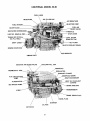
GENERAL INFORMATION
ENGINE:
Universal Diesel engines are four stroke engines. They are designed with special swirl combustion
chambers, balanced crankshaft system for minimum vibration and noise levels.
COOLING SYSTEM: All Models Except M-15
Engines are fresh water cooled, employing a rubber impeller sea water pump moving sea water
through a heat exchanger thereby lowering the temperature of the fresh water coolant. A fresh
water coolant supply is maintained in the expansion tank which is an integral part of the exhaust
manifold. Coolant level should be checked at regular intervals and at least once each season for
leakage, deposits and general condition. Always close the sea water cock before attempting any
work on the coolant system. (Note the make of sea water pump for service parts under general
information. )
COOLING SYSTEM: Model M-15
Engine is sea water cooled, having a rubber impeller sea water pump, with a recirculating
temperature control thermostat. The mixing tee is to be located below the engine and sea water
level to prevent air from entering the system causing overheating.
LUBRICATION SYSTEM:
Engines are pressure lubricated and use replaceable oil filters which should be changed regularly.
FUEL SYSTEM:
Tt'le fuel system utilizes either an electric on all current models or mechanical fuel pump on early
M-15 & M-40, fuel filter, fuel injection pump with injectors and necessary fuel lines. Unused fuel
coming from the injector nozzles is returned to the top of the fuel supply tank through a fuel return
line.
ELECTRICAL SYSTEM:
All models are equipped with a 12 volt starter and a 51 amp alternator. Battery cable connections
as well as all other electrical connections should be checked regularly. The V-belt driving the alternator and water pump should have finger pressure deflection of approximately 1/2".
1.
Battery ground cable (-) should be connected to a component or cylinder block which is
constructed of cast iron or steel.
2.
Do not connect to the transmission, bell housing or front timing cover case.
3.
It is recommended all ground connections are secure and properly coated to prevent corrosion or improper grounding. Check connection semi-annually.
6
GENERAL CARE:
If the boat is left afloat for periods of a month or more, the engine should be started at least every
14 days to prevent internal corrosion.
Regularly spray external unpainted surfaces and exposed, unpainted electrical equipment with a
corrosion and moisture protective coating.
ENGINE ALIGNMENT TO SHAFT COUPLING:
It is the responsibility of the dealer or yard to properly align the engine and shaft to within .002" to
.004" inches. The boat must be in the water when this is done. Alignment is not the responsibility
of Universal Motors. If not done properly damage to shaft and engine can occur, usually vibration
is present if alignment is off.
HAVE YOU MAILED IN YOUR WARRANTY CARD? A WARRANTY CARD MUST BE ON FILE FOR
WARRANTY WORK APPROVAL OR PROOF OF PURCHASE DATE.
--
PREPARATIONS FOR STARTING YOUR NEW DIESEL ENGINE
For long dependable service, become familiar with the operating requirements of your engine.
All Universal Diesel engines are completely factory tested under load conditions before shipment.
In preparation for starting engine, oil must be added to the crankcase. Refer to specifications for
lubrication, oil type and capacity. Recheck oil level on dipstick, it should be to full mark, do not overfill,
when checking oil remove dipstick, wait 15 seconds, then recheck.
The oil level should be checked before the first start-up each day. Dipstick has high and low markings.
Oil levels either above or below these marks should never be allowed. Oil is put into the engine by
removing the screw cap on the top of the rocker arm cover. Fill the crankcase with oil to the upper
mark on the dipstick and securely replace the filler cap.
THE TRANSMISSION IS SHIPPED WITH OIL, BUT SHOULD BE CHECKED PRIOR TO OPERATION.
Refer to specification of oil type and capacity. Recheck oil level on dipstick. (DIPSTICK TO BE INSERTED ONLY. DO NOT SCREW IN). See transmission instructions for additional information. FILL
TO INDENTED RING ON DIPSTICK only.
An unrestricted water supply must be provided to the engine. Use a minimum of 1/2" through hull fitting. Locate the scoop where it will have a full supply of water at all times regardless of running position or rough seas. A sea cock or gate valve is necessary at the water inlet point. The water pump has
a 3/8" N.P.T. suction inlet and the heat exchanger has a 3/8" N.P.T. water outlet. Use a noncollapsible hose for the suction side. A water strainer installed in the line ahead of the water pump aids
in preventing clogging of the cooling system. The exhaust pipe is 1-1/4" N.P.T.' on all models except
M-50, which is 1-112" N.P.T.
The fresh water manifold on all models except M-15 should be filled slowly to the bottom of the filler
cap. A 50/50 mixture of fresh water and antifreeze solution is acceptable as an all weather coolant,
eliminating the need to drain the fresh water system for cold weather operation or storage. A coolant
mixture may change based on climatic conditions in your area. The rust preventive will aid in reducing
rust formation if no antifreeze is used.
Model 15, being sea water cooled, draws its water directly from the sea, filling the engine system and
discharging the hot water overboard into the exhaust line.
Be sure water pump is lubricated by turning grease cup (if provided on your engine) clockwise 112 turn
at 30 hour intervals. Pumps with no grease cup do not require lubrications.
7
Transmission shifting controls must allow the clutch to engage in the full forward and reverse positions.
Restricted or partial engagement will cause undue wear. The transmission should always be in the
neutral position before starting the engine. Also, the transmission shifter arm must be at a 900 angle to
the transmission bracket cable when in neutral.
DO NOT LEAVE GEAR IN FORWARD DURING SAILING WITH ENGINE OFF.
On all models, the fuel line must be connected from the fuel tank to the electric fuel pump, then to the
fuel filter. On Model 15, connect directly to the fuel supply line. A fuel return line must be connected
from the injector nozzles to the top of the fuel tank so that the unused fuel can blow back into the fuel
tank. IT IS VERY IMPORTANT TO KEEP ALL FUEL LINES FREE OF DUST AND IMPURITIES.
THEREFORE, BLOW OUT LINES BEFORE CONNECTING.
Check fuel supply and make sure fuel lines are tight. Any fuel leakage must be corrected before any
attempt to start the engine. If fuel line leaks are discovered or any work is done on the fuel system, it
may be necessary to bleed the fuel system before the engine will start. (Refer to bleeding instructions
in this manual if that procedure becomes necessary.)
Check all electrical connections. A wiring diagram is included in this manual. GROUND IS NEGATIVE
and the ground terminal should be connected to the engine block. Make sure it is metal to metal contact, and securely tightened. Also, check the battery to be sure all cells are covered with electrolyte. Do
not allow flames or sparks near battery openings. Gases produced during normal battery charging are
EXPLOSIVE.
BEFORE STARTING THE ENGINE
1. HAVE SAFETY EQUIPMENT ON BOARD AND KNOW HOW TO USE IT.
2. VENTILATE ENGINE COMPARTMENT BY OPENING HATCHES, OR BLOWER IF INSTALLED.
3.
CHECK CRANKCASE OIL LEVEL ON DIPSTICK, SHOULD BE AT FULL MARK.
4.
CHECK TRANSMISSION OIL LEVEL. (Refer to transmission servicing.)
5.
CHECK FRESH WATER LEVEL IN MANIFOLD OR EXPANSION TANK IF INSTALLED, ON ALL
MODELS EXCEPT M-15.
6.
CHECK FUEL SUPPLY.
7
FUEL SHUT-OFF VALVE SHOULD BE OPEN.
8. SEA WATER VALVE TO WATER PUMP MUST BE OPEN.
9.
EXHAUST SHUT-OFF VALVE MUST BE OPEN OR END-PLUG REMOVED IF INSTALLED.
10. REMOVE ANY OBSTRUCTION CAUGHT IN AIR INTAKE SCREEN.
11. TURN MAIN BATTERY SWITCH "ON".
12. TURN IGNITION KEY TO "ON" POSITION, TO ENERGIZE ELECTRIC FUEL PUMP ON ALL
MODELS TO BLEED THE FUEL LINES AND FILTER. (THIS IS USUALLY COMPLETED BY THE
BOATBUILDER AT THE TIME THE ENGINE IS TESTED AND SHOULD NOT BE REQUIRED BY
CUSTOMER.)
8
STARTING THE ENGINE
1.
Have safety equipment on board and know how to use it.
2.
Ventilate engine compartment by opening hatches.
3.
Be sure engine compartment is thoroughly ventilated. (Run blowers for 4 minutes before starting
engine, if installed.)
4.
Turn blowers off after starting or before starting to eliminate excessive battery drain, if preferred.
5.
Transmission lever should be in neutral. (Center Position)
6.
Place throttle lever at 1/3 open position.
7.
Turn key to "ON" position to energize fuel pump, glow plug and oil pressure light. If your panel
uses a key switch start, go tOh)9.
8.
Press "Glow Plug" button for 30 to 60 seconds, depending on the outside temperature.
Continue to hold glow plug button while pressing "Start" button to crank engine. Release both
buttons immediately after engine starts. Go to 11.
NOTE: YOU MUST HOLD GLOW PLUG BUTTON IN TO ENERGIZE THE STARTER BUTTON
FOR CRANKING ENGINE.
PANELS WITH KEY SWITCH START
9.
Activate "Glow Plug" switch for 30 seconds to 1 minute, depending on the outside air
temperature. It may be necessary to hold the glow plugs on during the time the engine is cranked
in very cold outside temperatures.
10. Turn key to full "right" position to crank engine. Release key immediately after start. MAKE SURE
THE KEY RETURNS TO THE "ON" POSITION.
NOTE: When cranking engine, only crank engine for 10 seconds and pause for 10 seconds.
Repeat until engine starts. (See Caution printed on Starter Motor.)
11.
Check oil pressure light. (Should go out after engine starts.)
12. Ammeter should indicate "Charge", depending on battery condition.
12A. If you have a voltmeter in place of an ammeter, it should read 12.5 to 14.5 volts, indicating alternator is working.
13.
Check cooling system. (Make sure water pump is operating by checking for water coming out of
exhaust pipe with exhaust gases.) Temperature on gauge should gradually increase to 165°F to
195°F on all models except M-15. Temperature on Model 15, should read between 135°F and
155°F.
14.
If oil pressure light does not go out or no water overboard or temperature is not normal, STOP
ENGINE AT ONCE! Recheck all items listed to correct problem.
--
15.
If all indications are normal after start-up, continue to run engine for about 10 minutes to be sure
all systems remain normal and operating temperature is maintained.
16. With boat still SECURED to mooring and throttle reduced to idle, check transmission operation by
shifting from neutral to forward, to neutral, to reverse to neutral. Make sure no lines or obstructions are near the propeller.
17.
Stop engine after above check out has been accomplished and recheck oil and water levels.
9
CAUTION
COOLING SYSTEM IS UNDER PRESSURE AFTER OPERATION. REMOVE CAP
SLOWLY. COOLANT WILL BE VERY HOT, USE A RAG. YOU COULD GET
BURNED.
ENGINE BREAK-IN AND GENERAL RUNNING
1.
Engine break-in period should be approximately 10 hours of operation at 75% of normal cruising
speed.
2.
On your trial cruise, check the propeller shaft for abnormal vibration and engine mounts for
tightness. Realignment of the propeller shaft may be required if noticeable vibration is present.
Boat should be in the water when checking alignment. Universal is not responsible for shaft alignment, or locking nuts on mounts coming loose.
3.
After the break-in period, an average cruising speed for a sail boat installation is about 80% of the
maximum engine speed obtainable, to achieve hull speed.
4. Periodically check oil light indicators, ammeter, temperature and exhaust water for normal operation, this is the operators responsibility.
5.
When shifting transmission, engine R.P.M. should be reduced to idle, then shift transmission firmly from one direction to another. A slight pause in neutral will allow propeller to slow and add life
to transmission. In adverse conditions due to winds, sea, or higher RPM's it may be more difficult
to shift.
STOPPING THE ENGINE
1. Place throttle in the idle position.
2.
Place transmission shift lever in neutral. (Center position).
3. Leave engine idle for approximately 1 to 2 minutes for it to cool down.
4. To stop engine on early Models 15, 18,20,30 & 40, hold throttle lever in the back position
against the spring loading until the engine stops. Then release the throttle from the stop position
and throttle will return to the idle position. Repeat if engine does not stop the first time. Models
M-12, M-25, M2-12, M3-20, M4-30, M-25XP, M-35, M-40, M-SO have a separate stop lever for shutting the engine down. All newer models have a shut down lever on panel, pull
lever to stop engines, then tum off key. The newer models have a separate shut down lever.
5.
Tum key to the "OFF" position to shut off the electric fuel pump and accessories. If not in
"OFF" position, it may drain the batteries.
6. Open battery master switch ONLY AFTER ENGINE HAS COME TO A COMPLETE STOP!
This will prevent alternator and regulator damage.
7.
00 NOT USE THE DECOMPRESSION LEVER TO STOP THE ENGINE! This practice could
seriously damage the exhaust valves.
8.
You may want to close the fuel and sea water valves after stopping the engine. If so, BE SURE
TO RE-OPEN THEM BEFORE RESTARTING. FAILURE TO 00 SO COULD CAUSE ENGINE
TO OVERHEAT AND DAMAGE TO THE PUMP IMPELLER, OR FUEL LINES TO BECOME AIR
LOCKED. THIS SITUATION WOULD THEN REQUIRE BLEEDING OF THE FUEL SYSTEM
BEFORE RESTARTING ANDIOR REPLACING THE PUMP IMPELLER.
10
DECOMPRESSION LEVER
A decompression lever fitted to the engine enables the user to start the engine easier when it is extremely cold, when the battery is low or when bleeding the fuel system. There is no decompression
lever on Models 12, M2-12, M3-20, M4-30 and M-35.
-CAUTIONTHE DECOMPRESSION LEVER MUST NOT BE USED TO STOP THE ENGINE
EXCEPT IN EMERGENCY SITUATIONS SUCH AS RUN AWAY ENGINE OR
THROTILE DAMAGE, AS SERIOUS DAMAGE CAN BE DONE TO THE EXHAUST VALVES.
When the battery is weak or starting in extremely cold weather:
(In most cases decompression is not necessary.)
Models with Glow and Start Buttons and Decompression:
1.
Pull decompression lever to release position.
2.
Turn ignition switch to ON position.
3.
Hold Glow Plug Button in for 30 to 60 seconds then press Start Button to crank engine
(Models after early 1983).
4.
After 3 to 5 seconds, when the engine has gained momentum, return decompression lever to
its original position. Engine should now start.
Models With Start On Key Switch:
1.
Pull decompression lever to release position.
2.
Turn key to ON position.
3.
Energize glow plugs for 30 to 60 seconds.
4.
Turn key to start position to crank engine.
5.
After 3 to 5 seconds, when the engine has gained momentum, return decompression lever to
its original position. Engine should now start.
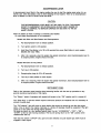
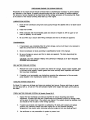
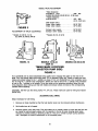
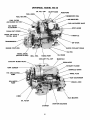
INSTRUMENT PANEL
Refer to the instrument panel drawing when becoming familiar with the start up procedure or any
general operating requirements of the engine.
The "Blower" switch (if equipped with engine) will remain in the "ON" position until it is turned off.
The "Glow Plug" or pre-heat switch requires continuous pressure for whatever time it is necessary to
activate the glow plug.
The "Oil Pressure" light will come on when starting the engine but should go out after the engine
starts. A low oil level in the engine crankcase or a serious oil leakage should be suspected if the light
comes on at any other time during engine operation.
Old style key switch is a four position selector type. Far left, "ACCESSORY"-"OFF"-"ON""START" at the far right moving clockwise. The key will spring return to the "ON" position when
released after start up.
New style key switch is ON-OFF only; glow and start switches are push button type. Both must be
engaged to start engine.
11
Operating temperature is approximately 165°F to 195°F on all models except M-15. Operating
temperature is approximately 135°F to 155°F on Model 15. The ammeter should indicate the charge required based on equipment and battery condition.
There are three (3) New style "Universal" panels.
1. Standard: Includes temp. and AMP gauges, oil light, on-off key switch, glow plug and start
300680 buttons.
2.
Deluxe:
300685
Same as Standard plus a tachometer with 4 selection stations on the back. To be
set to correct Model for accurate readings.
3.
Custom:
300690
Same as Standard plus a tachometer/hour meter with Model selection station on
back and a low-oil high-temp audio alarm with red light.
KEY START PANELS
®€)®
@bJ ~ IUNIVERSAL I ® ~
~~
IUNIVERSAL I ®
CD
DEWXE
STANDARD
BUTTON START PANELS
(Replace With Panels Below)
(@) (@)
UNIVERSAL
G)
CD
STANDARD
300680
@~o©
®8®
(@) (@)
UNIVERSAL (!)
(@) (@)
CD
DEWXE
300685
UNIVERSAL
CUSTOM
300690
FIGURE 1
12
@ CD
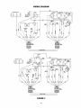
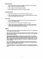
WIRING DIAGRAM
....... " ' - (' PO< cyI.)
.
X
~
!
iii
o
~~-:-----------------~------Hwneg-----------------------~-~~~: :
Glow Plugs (1 per tyI.)
..
".!!
.
".!!
~
~
c
!
0
~
'"
~
."
~
j!
.
~
iii
6
~~-:----------------~----~H-'-mep---------------------~-:---~: :
FIGURE 2
13
PREPARING THE ENGINE FOR WINTER STORAGE OR LAYUPS
Proper preparation of your engine for storage will avoid damage and minimize expense when agai,n
placing your engine in service.
NOTE: It is recommended that your engine be winterized by an authorized Universal mechanic or at
least, a trained mechanic familiar with the engine and its options.
LUBRICATION SYSTEM:
1.
Before boat is lifted out of the water, run the engine until operating temperature is attained.
2.
Stop engine after warm up and remove crankcase oil through the dipstick hole using hand
sump pump designed for that purpose. Replace dipstick after oil has been removed or
through oil drain hose if one is provided. The newer engines have a drain hose for changing
crankcase oil.
3.
Refill crankcase with new oil and replace filler cap.
4.
Run engine again for about 5 minutes to distribute a protective film of clean oil to act as a
rust preventive during storage.
TRANSMISSION: (See transmission instructions)
1.
Fill transmission completely with type AFT or DEXRON II transmission oil. You may just add
to the existing oil or drain the old oil and completely refill with new transmission oil.
2.
Be sure both drain and filler plugs are tight after draining or adding to the oil in the
transmission.
3.
Transmission is now ready for storage.
SEA WATER COOLING SYSTEM: All Models Except M-15
OPTION #1 (Dry Storage)
1. To drain sea water system, disconnect hose end at sea water pump that comes from heat
exchanger.
Lower free end of hose to a pOint approximately level with the front engine mount. This will
allow the sea water to drain from heat exchanger and hoses.
2.
Loosen the 4 or 6 screws on the sea water pump cover plate. Tap the plate lightly to loosen
it, this will allow pump to drain.
3.
After pump has drained, apply a light coat of lubrication to protect pump and impeller during
storage and replace cover.
4.
Dr~in
exhaust muffler and system separately.
OPTION #2 (Wet Storage)
Repeat Steps 1, 2 and 4 of Option #1
1.
Disconnect sea water inlet hose at sea cock shut off valve. BE SURE SEA INLET VALVE IS
CLOSED FIRST.
2.
After the inlet hose has stopped draining, place hose into a (2 Gallon) container of antifreeze. Start engine and run the two gallons on antifreeze through the system until the antifreeze comes out the exhaust outlet, stop engine and check item 4. Make sure you do not
run out of antifreeze while engine is running.
14
3.
You should now have antifreeze in sea water pump, hoses, heat exchanger and exhaust
system.
4.
If aqua-lift or pot type muffler is used, it is recommended to drain prior to pumping antifreeze thru system and afterwards to prevent coolant from backing up into the engine.
SEA WATER COOLING SYSTEM: Model M-15
OPTION #1
1. Open the cylinder block drain cock on the side of the block where hose from water pump
enters, and drain.
2.
Loosen water pump cover plate, allowing pump to drain, lubricate and replace cover.
3.
Remove drain plug or rear bottom of exhaust manifold, and drain.
4.
When boat is out of water, inlet lines to pump and thermostat will drain. Close sea cock
valve when completed for storage.
5.
If aqua-lift or can type muffler is used, it is recommended to drain muffler and lines of water.
OPTION #2 (With engine at operating temperature and stopped)
1.
Shut off sea cock valve.
2.
Remove hose at sea cock. Let water drain from hose. Place inlet hose into container of antifreeze (with decompression lever on). Crank engine over at 10 second intervals until antifreeze comes out exhaust outlet.
3.
If aqua-lift or can type muffler is used, drain prior to pumping antifreeze thru system and
afterwards to prevent coolant from backing up into the engine.
4.
You may wish to do option -1 prior to -2 to insure all water is out of engine and exhaust
system.
5.
Replace hose to sea cock when complete. Be sure sea valve is closed.
6.
Antifreeze will aid in coating inside of the engine, reducing rusting.
TO DRAIN FRESH WATER COOLING SYSTEM: All Models Except M-15
1.
Remove pressure cap from manifold. (when engine is cool)
2.
Open drain cock located above oil filter to drain engine block and head cylinder.
3.
Open the in-line drain petcock located below the alternator. This will drain the manifold, heat
exchanger and engine fresh water pump.
4.
Remove 1/8" pipe plug at lower rear of manifold, to drain manifold separately.
5.
Close all drain valves and petcocks when draining has been completed.
6.
If antifreeze solution is used, it is not necessary to drain the system each year, providing you
have the correct mixture to prevent freezing during winter storage.
15
EXHAUST SYSTEM:
1.
Exhaust pipes and muffler should be drained of sea water. Allow the exhaust pipes to dry
out. Seal exhaust pipe end to prevent entrance of moisture into the engine through exhaust
valves that are open.
2.
See Option -2 under Sea Water Cooling System appropriate for your model.
3.
All can type mufflers should be drained after any long periods of cranking, as Sea Water
pump will fill the muffler causing water to backup and enter the engine.
ELECTRICAL SYSTEM:
1.
Remove battery and store it in a warm dry area.
2.
Protect other electrical parts against moisture.
FUEL TANK:
1. To protect against corrosion or moisture in the fuel supply tank, either fill the tank with fuel
or drain completely and seal top securely for storage.
2.
A diesel additive is recommended to prevent bacterial growth in the fuel.
GENERAL:
You may want to completely cover the engine to provide additional protection. Care should be
taken when covering so that electrical connections are not loosened and that fuel lines are not
bent or broken.
HAVE YOU MAILED IN YOUR WARRANTY CARD? A WARRANTY CARD MUST BE ON FILE FOR
WARRANTY WORK APPROVAL, OR PROOF OF PURCHASE DATE.
16
PREPARING ENGINE FOR SPRING SERVICE
Preparation of the engine should include all those items of maintenance necessary to permit satisfactory operation of the engine. A properly serviced engine will give a full season of carefree pleasure.
The amount of service needed will be determined by the storage procedure of the previous fall. Refer
to the section of the manual covering initial start up of the engine.
LUBRICATION SYSTEM:
1. Drain oil from crankcase using hand sump pump through the dipstick hole or oil drain hose if
installed.
2.
Install new oil filter.
3.
Refill crankcase with recommended grade and amount of engine oil. (Fill to upper or full
mark on dipstick). Do not overfill.
4.
Be sure filler cap is secure after filling crankcase and that no oil leaks are apparent.
TRANSMISSION:
1. If transmission was completely filled for winter storage, some oil will have to be removed to
attain the correct level in the transmission.
2.
Check transmission oil level according to specifications found in this manual.
3.
Be sure all plugs are secure and that no leaks are apparent. The drain plug should be
checked regularly.
CAUTION: DO NOT CROSS THREAD THE DIPSTICK THREADS AS IT MAY REQUIRE
HOUSING REPLACEMENT.
SEA WATER COOLING SYSTEM:
1. Remove front cover of pump if system was drained for storage. Inspect rubber impeller, lightly lubricate pump impeller, replace gasket and cover securely when inspection and lubrication have been completed.
2.
If impeller is not serviceable, see instructions covering the replacement of the sea water
pump impeller in the maintenance section of this manual.
COOLING SYSTEM: Model M-15
On Model 15, make sure all plugs and hoses are replaced and secure. Remove inlet hose on pump
and add about 314 oz. of lube oil. This will lubricate impeller when engine first starts until it picks up
sea water.
FRESH WATER COOLING SYSTEM: All Models Except M-15
1.
Inspect the heat exchanger and exhaust manifold for secure mounting and interior
cleanliness. If system was filed with a 50/50 water and antifreeze mixture for storage, leaks
will be easier to detect than if the system was drained. The coolant should be relatively clear
and should be free of scale or other foreign particles.
2.
If system was drained and inspection is satisfactory, fill slowly with coolant and replace
pressure cap. Recheck coolant level after engine has run and reached operating
temperature. Use caution when removing cap when engine is hot, you could get burnt.
3.
Use antifreeze or rust preventative in system to prevent rust.
17
EXHAUST SYSTEM:
1.
Check all hoses and hose clamps for serviceability and security. Any worn or damaged
hoses or clamps must be replaced before operation.
2.
Check all valves and remove all plugs before operation.
3.
Check complete system monthly for leaks, make repairs as needed.
ELECTRICAL SYSTEM:
1.
Inspect all wiring, terminals, controls and switches for damage or corrosion.
2.
Install a fully charged battery and connect it correctly. (NEGATIVE GROUND.) Be careful to
not short across negative and positive terminals.
FUEL SYSTEM:
1. Fuel tank must be clean, free of water and securely mounted. If it was filled with fuel for
storage, FUEL MUST BE CLEAN.
2.
Check fuel cap vent hose. It must be open for unrestricted air venting.
3.
Fuel lines must be secure and all clamps and nuts tight. Lines must not be leaking. Fuel
system will require bleeding before operation, if tank has been drained or filter has been
replaced. (See instructions covering fuel system bleeding).
GENERAL:
All of the above items must be carefully checked if satisfactory operation is to be expected, good
common sense will aid during servicing.
Refer to the start up check list in this manual after above items have been checked and before attempting to start the engine so that the proper procedure may be followed. In some cases other
add ons may require serviCing.
WITH THE BOAT IN THE WATER, check freedom of the propeller shaft in the bearings and
alignment of the propeller shaft with the engine. Shaft alignment should not be more than .002" to
.004" out at four pOints in one position at coupling flange and the same four pOints in the same
position when shaft and coupling is rotated 1800 from first check. If propeller shaft is out of alignment, we strongly recommend that re-alignment be performed by a qualified mechanic familiar
with the installation.
Also, it may be necessary to tighten the stuffing gland just enough to stop excessive leakage
along the shaft. Excessive tightening will cause power loss and burned stuffing material. A slight
seepage is necessary to lubricate the stuffing gland.
Any problems arising from this pre-use inspection requiring special tools or attention should be
referred to the boat dealer, a Universal Dealer service center, or a qualified diesel engine service
center.
18
MAINTENANCE OF YOUR ENGINE
Unless major repair work is done on the engine, timing should not be required.
FUEL INJECTION TIMING:
Basic tools required: (A) - 10 MM
(B) - 13 MM
(C) - 17 MM
(D) - 12 MM
(E) - 27 MM
Socket wrench
Socket wrench
Open end wrench
Box end wrench
Socket (1-1/16")
Engine firing order - Two cylinder - 1 - 2
(Front V belt end)
Three cylinder - 1 - 2 - 3
Four cylinder -
1-3-4-2
1. Remove fuel lines from injector pump fittings on injector pump (Tool C).
2.
Pull decompression lever so that it will remain in the decompression position. No decompression lever on Model-12.
3.
Open throttle fully.
4.
Energize electric fuel pump and turn engine over with starter to ensure that fuel is coming
out of each injector pump opening. Have clean rags around opening to soak up fuel.
5.
Wipe off any fuel on injector pump body and the top of each injector opening.
6.
Turn crankshaft over by hand, being careful not to damage spline on end of crankshaft.
Engine rotation will be clockwise. STOP IMMEDIATELY at the first sign of fuel movement in
the injector pump fuel fitting, for whichever injector pump is being checked. (No. 1 injector
pump is the closest to the V-belt end of the engine).
7.
Remove cover from flywheel timing mark inspection hold located inside of left engine mount
(Tool B).
8.
Check alignment of mark on flywheel with the timing pointer on the wall of the inspection
hole. The 1-FI mark on the flywheel represents fuel injection of No.1 cylinder.2-FI
represents No.2 cylinder, etc.
9.
If timing pointer and the flywheel marking 1-FI is aligned then No.1 cylinder is properly timed for fuel injection and should require no adjustment. The same will be true for No.2, No. 3
and No. 4 cylinders if the above steps are followed.
10. In order to determine if timing is off, or if the injection pump is faulty, it is necessary to
recheck the timing for each cylinder two or three times.
11
If there are variations in repeatability in the alignment of pOinter and timing mark, a faulty
fuel injector pump may be suspected.
12.
If timing marks repeat to same location but are off 3/16" or more above or below the pointer,
this indicates that the engine must be retimed.
If alignment of the timing mark is not within 3/16" above or below the pointer, the above steps must be
taken to time the engine. If the timing is found to be satisfactory, then reconnect all fuel lines and fittings and tighten. The fuel system must be bled beforeh)the engine will operate properly. (See fuel
bleeding instructions on page 28).
19
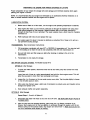
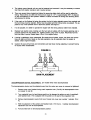
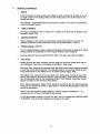
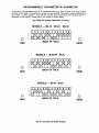
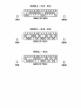
DIESEL VALVE ADJUSTMENT
"Valve clearance
M-12-M2-12, 15-18 ................006 - .0(]7
M-25XP-35, M3-20, M4-30 (0.145 - 0.185 mm)
""Valve Clearance
M-20-30-40-50 . . . . . . . . . . . . . . . . .. .0(]7 - .009
(.0.18 - 0.22 mm)
(with engine cOld.)
Intake valve opens.............. 200 B TDC
Intake valve closes .............. 450 A BDC
FIGURE 3
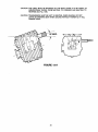
ADJUSTMENT OF VALVE CLEARANCE
.. Models 12, M2-12, 15, 18,
25, 25Xp, 35, M3-20, M4-30
Exhaust valve opens. . . . . . . . . . . .. 500 B BDC
Exhaust valve closes............ 150 A TDC
""Models 20, 30, 40 & 50
.
"
tn
:::E:"
e
W
W
Z
Z
az
az
w
w
MODEL 12
MODELS 15-18-25
25XP 35
...I
...I
W
CD
W
Z
az
w
MODELS 20-30-40-50
TIMING MARK LOCATIONS
(INJECTOR PUMP SIDE)
FIGURE 4
Turn crankshaft over by hand (Clockwise) being careful not to damage the spline on the end of the
shaft. Turn until pointer aligns with timing mark 1TC on flywheel (Figure 4A). Check to make sure both
intake and exhaust valves on No.1 cylinder are loose. If not, turn crankshaft one more complete revolution to bring No. 1 cylinder onto compression. Valves can now be set on No. 1 cylinder.. This procedure
is true for No. 1 cylinder on all models. To set the valves on the remaining cylinders, follow the matching diagrams above being sure that both intake and exhaust valves are loose at the corresponding
cylinder before adjusting.
CAUTION: DO NOT use the timing marks 1-FI, 2-FI, etc. These marks are used for timing fuel injector
pumps only.
ADJUSTING FUEL TIMING
Steps necessary for fuel timing:
1.
Remove air intake manifold so that the fuel injector pump can be removed without interference.
2.
Set throttle lever at full speed.
3.
Remove injector pump side cover. This will enable you to visually check to insure that the fuel rack
pin jnside the pump properly aligns with the opening in the top of pump housing when being
removed to prevent binding or shearing of the pin. This pin is critical to proper pump operation
and if damaged will require replacement of the complete pump.
20
4.
The injector pump internal unit can now be loosened and removed. It may be necessary to remove
fuel lines from injector nozzles to aid in pump removal
5.
There are several shims located just below the pump top plate which will be used to adjust the
timing. These shims are .006 inch thick and are equal to 1-V2 ° or approximately 3/16" of distance
on the circumference of the flywheel. Addition of shims will retard the timing and removing shims
will advance the timing.
6.
If the mark on the flywheel is below the pointer, the fuel is being injected sooner than required and
the fuel timing must be retarded. Shims must be added until the timing marks are aligned. The opposite is true if the flywheel mark is above the pointer. See figure 5.
7.
If at all possible, it is better to operate the engine with the timing advance rather than retarded.
8.
Replace fuel injector pump, making sure the fuel rack pin aligns with the housing opening and is
properly inserted into the slotted arm. Tighten injector pump cover in place. Reconnect fuel line
from fuel filter to pump. Repeat steps 2 thru 12 on engine timing.
9.
If timing is satisfactory, then reassemble. Be certain that all plates, covers, fuel lines and connections are tight and free of leaks so that safe operation may be expected when the engine is
started. Clean engine throughly.
10.
Caution: Be sure all fuel lines and connections are kept clean during adjusting, to prevent fouling
of nozzles when reassembled.
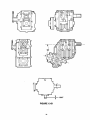
FIGURE 5
SHIM PLACEMENT
DECOMPRESSION DEVICE ADJUSTMENT: (on models which have decompression)
The decompression device must be adjusted every time the rocker arm cover is removed or tightened.
1.
Remove cover over flywheel timing mark inspection hole. (Tool B). No decompression lever
on models 12 and 35.
2.
Turn crankshaft over by hand being careful not to damage the spline on end of crankshaft,
until flywheel mark 1-TC is aligned with the pointer on the wall of the inspection hole.
3.
Remove decompression covers from top of rocker arm cover over number 1 cylinder. (Tool
A).
4.
With the alignment of the pointer and flywheel mark 1-TC the no. 1 cylinder decompression
adjustment can now be accomplished.
5.
Pull and hold lever to full decompression position.
21
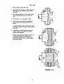
6.
Working through the access hole, loosen the lock nut with a wrench (tool A) and back the
adjusting screw off until no contact is made on the rocker arm (Using screw driver).
7.
Now tum adjusting screw in until first contact is made, continue to tum screw in (1) turn.
8. Lock the screw in this position with the lock nut. Observe the position of slot in screw prior
to locking nut, recheck after tightening lock nut.
9. The above stops are to be followed to adjust the decompression for all remaining cylinders.
After aligning the respective flywheel marks (2-TC, 3-TC, etc.). Adjustments can be made
described in steps 3 thru 7 above.
as
10. After all necessary adjustments have been made, be sure to replace and secure all access
hole covers and the flywheel inspection hole cover.
DECOMPRESSION DEVICE
FIGURE 6
FUEL SYSTEM:
The fuel system utilizes either an electric or mechanical fuel pump, fuel filter, fuel injection pump with
injectors and fuel lines. Any fuel not used by the injectors is returned through fuel return lines from the
rear most nozzle to the top of the fuel supply tank.
ALL MODELS AFTER 1986 HAVE ELECTRIC FUEL PUMPS
The canister type fuel filter should be changed each season before the engine is placed back in service or more often based on engine usage.
The engine operates on No.2 diesel fuel only and care should be taken to see that no water or dirt
enters the fuel system.
Clean fuel is very important to a smooth, trouble free running engine. Add a fuel additive to prevent
algae growth.
PLEASE MAIL IN YOUR WARRANTY NOW!
22
FUEL SYSTEM
I
I
,
I
\
I
U
1
(Early M-15 & M-40)
FIGURE 7
23
BLEEDING THE FUEL SYSTEM:
It will be necessary to bleed the fuel system to achieve a steady air free flow of fuel if any of the follow.
ing have occured: Models M-12, M2-12, M3-20, and M4-30 have self bleeding fuel systems.
1.
Running out of fuel.
2.
If fuel shut off valve is left closed and engine runs out of fuel.
3.
Replacing fuel filter.
4.
Fuel injector nozzle or injector pump repair.
5.
After repairing or replacing any fuel line.
6.
Before putting engine back into service in the spring, if fuel system has been drained.
7.
Replacement of electric or mechanical fuel pump.
8.
Any time air is permitted to enter the fuel system.
BLEEDING PROCEDURE:
Be sure to have some means available to catch or absorb any fuel escaping during the bleeding process so that it will not accumulate in the engine compartment or bilge.
1. Be sure there is a sufficient supply of fuel in the fuel tank.
2.
Open the fuel shut-off valve at the tank.
3.
Start the electric fuel pump by turning the ignition key to the "ON" position on models 18,
20, 25, 30, 50, all models after 1986.
4.
Model 15 has a mechanical fuel pump. Therefore with decompression on, turn engine over
with starter. Crank at 10 second intervals while doing steps #5 and 7.
5.
Slowly loosen the air bleed plug on the fuel filter, letting air escape until an air free flow of
fuel is evident. (1986 models see item 7).
6.
At this time, tighten the air bleed plug on the filter.
7.
Slowly loosen the air bleed plug on the injector pump, letting air escape until an air free flow
of fuel is evident. Units with a self bleed return valve, open for a short period then start
engine, as soon as engine runs smooth close valve. Model-12 has continuous fuel bleeding.
8.
At this time, tighten the air bleed plug or knurled knob on the injector pump.
9.
The fuel system should now be properly bled and ready for operation.
Refer to starting instructions before attempting to start the engine after bleeding the fuel system.
CAUTION: Excessive cranking with sea cock valve open can cause water accumulation in
the muffler and possibly back up into the engine. Drain muffler as needed.
FUEL INJECTORS:
Fuel injectors should be removed and taken to a qualified diesel engine repair center to be tested for
leakage and spray pattern, if poor engine performance such as loss of power, rough or uneven running, sudden notice of dark exhaust, or engine becomes hard to start.
24
REMOVING INJECTORS:
1.
Clean the area around the injectors before removing.
2.
Loosen nuts holding fuel lines to injector pump and injector nozzle and remove fuel lines
(fool C).
3.
Loosen "nuts on return line adapters "and remove adapters (fool C.)
4.
Loosen injectors (using Tool E) and remove injectors.
REPLACING INJECTORS:
1.
Check to be sure contact surfaces and area around injectors is clean.
2.
Replace injectors in the same cylinder from which they were removed.
3.
Torque required to properly seat the injectors will be between 43 and 58 ft./lbs.
4.
Replace fuel return lines and secure nuts.
S.
Replace all fuel lines and secure all nuts.
6.
After all injectors, fuel lines and hoses have been replaced and are secured, the fuel system
will have to be bled. (Refer to bleeding instructions in this manual. (P-27)
The fuel injection pump has been set at the factory and should need no adjustment. Any apparent problem with the pump should be referred to a qualified diesel mechanic or to a Universal Diesel dealer as
advised.
NOTE: NO WARRANTY COVERAGE WILL BE GRANTED IF ANY OF THE FACTORY SET
AND SEALED FUEL AND MAXIMUM R.P.M. ADJUSTMENTS ARE ALTERED.
OIL FILTER CHANGE:
After draining engine oil and before refilling with new oil, the oil filter should be changed.
1.
Unscrew old filter. If it will not loosen, use a speCial oil filter removal tool.
2. Take care to catch any escaping oil so that it will not accumulate in the engine compartment.
3.
When installing new filter, moisten the rubber seal with oil, screw new oil filter onto the
threaded shaft and tighten it. Hand pressure is sufficient to tighten the filter.
4.
Refill the crankcase with the correct grade and amount of oil as indicated by the full mark on
dipstick.
S.
Start the engine according to the starting procedure in this manual. Run only long enough to
check for any oil leaks and stop engine.
6. The oil level will have dropped by the amount of oil which enters the oil filter and by the
amount which has distributed around the engine.
7.
After engine has stopped and the oil level allowed to settle, recheck the oil level and fill as
required.
2S
WBE OIL FILTER
FIGURE 8
UNIVERSAL RECOMMENDS THAT YOU USE FACTORY REPLACEMENT FILTERS. THE USE OF
OTHERS MAY VOID THE ENGINE WARRANTY.
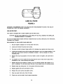
SEA WATER PUMP:
Your engine is equipped with a rubber impeller type sea water pump.
CAUTION: DO NOT RUN PUMP DRY AT ANY TIME OR YOU WILL DAMAGE THE IMPELLER,
CAUSING ENGINE TO OVERHEAT.
You can use methyl alcohol based anti-freeze compounds such as Zerex, Shell Zone, Pyro Permanent,
Permagard and Dowgard.
REPLACEMENT OF SEA WATER PUMP IMPELLER:
1.
Be sure engine is stopped. Turn off sea water inlet valve.
2.
Loosen and remove the pump cover screws.
3.
Tap cover on side to loosen, being careful not to damage cover gasket and remove cover.
4.
At this time be careful not to pull the pump shaft forward or out of its present position. If the
shaft does come forward during the changing of impeller, it will be necessary to remove
complete pump.
.
5.
Remove the snap ring located on the end of shaft in center of impeller, with shaft held in
place.
6.
The impeller can now be pulled off the pump shaft. Be sure to hold shaft in place with a
screwdriver or etc., when removing the impeller.
7.
Replace with the new impeller by rotating. (You can lubricate impeller with vaseline or oil
prior to installing.) This will also prevent burning of new impeller when first starting engine.
8.
Replace snap ring, being sure it is in the groove all the way around.
9.
Replace gasket and cover (oil inside of cover).
10. Replace the cover screws and tighten evenly.
11. Open sea water inlet valve, check for leaks.
12. Engine can now be started, check engine temperature.
26
NOTE: IF DURING IMPELLER REPLACEMENT THE PUMP SHAFT CAME FORWARD, IT
COULD HAVE COME OUT OF THE GROOVE AND DRIVE ADAPTOR. IF SO, YOU MUST COMPLETE THE FOLLOWING. NOTE - ON NEWER UNITS WITHOUT A MOUNTING SPACER BETWEEN THE PUMP AND ENGINE BLOCK YOU DO NOT HAVE A DRIVE ADAPTOR TO BE CONCERNED ABOUT. HOWEVER, YOU MUST ALIGN THE SHAFT TANG AND THE DRIVE
GROOVE WHEN REINSTALLING THE PROPELLER SHAFT.
1.
Loosen and remove the two capscrews holding the pump body to engine.
2.
Slowly move pump away from engine as the adaptor will come out.
3.
Complete the replacement of impeller as noted above.
4.
The pump shaft will now be protruding through the body mounting flange.
5. -Place the adaptor on to the pump shaft aligning the pin on the groove. On later models this
may not be present, the pump may mount direct to engine block.
6.
Align the slot on the other side of adaptor with the drive shaft in engine and place pump on
engine.
7.
Hold in place and start the two mounting capscrews. TIGHTEN FINGER TIGHT SO PUMP
IS FREE TO MOVE AND ALIGN ITSELF. ON 1987 MODELS THE PUMP HAS A PILOT
FOR SELF ALIGNING, JUST MOUNT AND TIGHTEN.
8.
Open sea water valve and start engine at idle. This will align pump to the drive and adaptor.
9.
Stop engine - now tighten capscrews carefully.
CAUTION: BE VERY CAREFUL DUE TO V-BELT MOVING ON FRONT OF ENGINE.
10.
Feel the bearings to make sure they ·are not hot; they are located in the center of pump
body.
11.
Alignment of pump can also be accomplished by turning engine over with the starter while
decompression lever is in the open position, approximately 5 to 10 revolutions. Release
starter button and decompression lever - tighten water pump screws.
NOTE: THERE ARE TWO TYPES OF SEA WATER-RUBBER IMPELLER PUMPS USED. ORBERDORFER PUMP HAS 4 SCREWS SECURING COVER TO PUMP BODY AND SHERWOOD
PUMP WHICH HAS 6 SCREWS SECURING COVER TO PUMP BODY. NOTE WHICH PUMP
YOU HAVE ON COVER OF THIS MANUAL. IT IS RECOMMENDED TO HAVE A SPARE IMPELLER AND COVER GASKET ON BOARD AT ALL TIMES.
ORBERDORFER IMPELLER NO. 295628
SHERWOOD IMPELLER NO. 287439
COVER GASKET NO. 295626
COVER GASKET NO. 295745
CAUTION: DO NOT RUN PUMPS DRY OR WITH SEA INLET VALVE CLOSED. LACK OF
WATER WILL CAUSE EXCESSIVE HEAT BUILD UP DAMAGING OR DESTROYING THE RUBBER IMPELLER, AND ENGINE WILL OVERHEAT.
IF VANES COME OFF IMPELLER THEY MUST BE LOCATED AND REMOVED TO INSURE
THEY ARE NOT BLOCKING OR RESTRICTING THE COOLING WATER FLOW IN THE ENGINE,
HOSES, OR FITTINGS.
\
NEW STYLE PUMPS HAVE A PILOT AND CAN BE MOUNTED AND BOLTED TIGHT WITHOUT
TURNING THE ENGINE OVER.
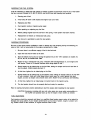
27
1.
2.
3.
4.
5.
6.
7.
8.
9.
10.
11.
12.
13.
14.
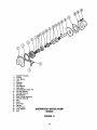
15.
Cover Screws (6)
Pump Cover
Cover Gasket
Impeller Snap Ring
Impeller
Key
Pump Shaft
Water Seal
Cam
Pump Body
Cam Locking Screw
Oil Seal
Drive Adaptor - Not used on Newer Models
Roll Pin
Drain Plug
SHERWOOD RUBBER IMPELLER PUMP
(PIN 300986)
FIGURE 9
28
1.
2.
3.
4.
5.
6.
7.
8.
9.
10.
11 .
12.
13.
14.
15.
16.
Cover Screws (4)
Pump Cover
Cover Gasket
Impeller Snap Ring
Impeller
Key
Pump Shaft
Water Seal
Cam
Pump Body
Cam Locking Screw
Oil Seal
Drive Adaptor - Not used on Newer Models
Roll Pin
Grease Cup
Drain Plug
OBERDORFER RUBBER IMPELLER PUMP
(PIN 301357)
FIGURE 10
29
1
2
3
4
5
6
7
8
9
10
11
12
13
14
15
16
17
18
19
20
21
Impeller Housing
O-Ring
Cam Screw
Cam
Impeller
Cir-Clip
Flat Washer
Seal Seat
Not Available Order #13
Cir-Clip Internal
Cir-Clip External
Ball Bearing
Seal & Seat Assembly
Cir-Clip External
Key
Shaft
End Plate
Gasket
Pump Body
Lock Washer
Bolt
SHERWOOD WATER PUMP
302648
FIGURE 11
30
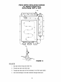
MODEL 15 SEA WATER CIRCULATION
Normal Range 1350 to 1440 F
r - ----------------1
I
I
I
I
I
\
I
~
I
1
I
1
I
:
I
I
I
IL.. _ _ _ _ _ _ _ _ _ _ _ _ _ _ _ _ _ _ 1I
FIGURE 12
1. Sea water enters thru sea water inlet,
2. Through sea water valve when open,
3.
Into mixing tee to suction side of pump, located below water line.
4.
Out of pump by hose to inlet on side of block.
5.
Circulates through block into cylinder head,
6.
Leaves head on top front to exhaust manifold,
7.
Circulates through manifold to thermostat,
31
8.
Enters thermostat which remains closed during warm up, permitting a small amount of water
to enter exhaust system for cooling and overboards.
9.
As engine temperature rises the
haust line. At the same time the
replace the discharge hot water.
engine (or water line) to prevent
thermostat starts to open, permitting hot water to enter exsame amount of cool sea water is drawn in by the pump to
This is done through the mixing tee which is located below
air from entering the system.
10. There may be some fluctuation in engine temperature until engine stabilizes.
11.
In areas of cold inlet say 50°, you may notice some movement from 135° to 155° as engine
R.P.M. are changed. This is less noticeable with warmer inlet water. The reason being that
the colder water causes thermostat to react faster than engine temperature stabilizes.
12.
It may appear at first that no water is being pumped overboard with the exhaust gases.
However as long as water temperature is within operating range (135° - 155°), there is a flow
of water being pumped overboard which may be noticed ·only as a fine mist. This will continue until the thermostat directs the water flow overboard to allow for greater intake of
cooler sea water.
32
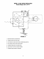
FRESH WATER CIRCULATION DIAGRAM
ALL MODELS EXCEPT M-15
Normal Range 1650 F to 1950 F
......
,
~:a.
- .......
--~-
/--~---'\
I
I
I
f
\'-.. ...... -____
.
.
I
\
,
/-~--'"
f
"-- ...... --......
~~-
,
J
t
I
I
II
I
I
I
\.....
,
I
I
•I
•I
I
+
-~-)
+
-)
FIGURE 13
SEA WATER
1. Sea water enters through sea water inlet,
2.
Through sea water valve when open,
3.
Through sea water pump into heat exchanger to cool fresh water system,
4.
From heat exchanger to sea water overboard through exhaust port.
33
FRESH WATER
1.
Coolant (fresh water with antifreeze) is introduced into the system from the coolant section of
exhaust manifold by removing pressure cap and filling manifold tank to within one inch of
lower rim of fill port.
2.
Fresh water engine driven circulating pump moves coolant from heat exchanger through
engine block circulating pump and thermostat back through exhaust manifold into heat exchanger to be cooled.
The manifold serves as the engine expansion tank to allow for expansion of coolant as it is
heated. You also fill the system at this point. In some cases when hot water heaters are installed an expansion or surge tank may be required to prevent air from entering the system.
Should your engine overheat, first check coolant level to make sure it is not low which would
cause air locks to develop. If air does enter the system, it may require a couple of fillings to
remove the air pocket. A momentary increase of engine R.P.M. to approximately 2800 to
3000 R.P.M. may aid in moving the air from the system. In some cases it may require dOing
this 2 or 3 times. Do this just as you notice the temperature starting to rise above normal.
34
UNIVERSAL DIESEL WITH HURTH TRANSMISSION
Model HBW-SO (2:1)
Used on Models 12, M2-12, M-18, M3-20, M4-30, M2S and M-2SXP
Model HBW-100 (1.8:1)
Used on Models 30, 3S, and 40
Model HBW-1S0 (1.9:1)
Used on Model SO
Model HBW-1S0 V-Drive (2.13:1)
Used on All of our V-Drive Models
TABLE OF CONTENTS
A. Description
B. Servicing
C. Maintenance
D. General Information
E. Illustrations
CAUTION
DO NOT LEAVE GEAR IN FORWARD WHEN SAILING. GEAR MUST BE IN NEUTRAL FOR FREE
WHEELING OR SHIFTED INlO REVERSE TO LOCK PROPELLER WHILE SAILING.
35
A.
DESCRIPTION:
The Hurth transmission housing is made of a high strength aluminum alloy that is resistant to sea
water. The transmission is equipped with shaved and case hardened helical gears and with shafts
mounted in heavy-duty roller bearings. Forward and reverse is accomplished by a mechanical friction clutch.
Gear shifting is mechanical and requires only a minimum effort on the gear lever. Precision setting or readjustment of the shifting control (Morse or Teleflex) is not required.
The transmission is designed to permit reversing at full engine speed. TO BE USED ONLY IN
THE EVENT OF AN EMERGENCY!
B.
SERVICING:
The transmission is filled with Type AFT or DEXRON II transmission fluid at the factory during the
engine load test.
Recheck and fill the gear box with the prescribed oil up to the FULL INDENTED RING
MARK ON THE DIPSTICK (approximately 1/4" up from bottom of stick). Do not overfill.
When checking the oil level, DIPSTICK TO BE INSERTED ONLY - DO NOT SCREW IN.
Tighten the dipstick after adding oil or checking the oil level.
FULL 1.
Placing in service after storage.
If the transmission was completely filled with oil for storage and preservation, make sure to
drain the excess oil to the proper level. Use new oil if necessary.
2.
Oil quantity.
Approximately
3.
Oil grade.
Transmission Fluid
Quantity
HBW50
0.29 Quarts (O ..30 Liters)
HBW100
0.33 Quarts (O.35 Liters)
HBW150
0.59 Quarts (O.56 Liters)
HBW 150V
1.10 Quarts (1.05 Liters)
Automatic Transmission Fluid, "AFT Type A oil only" according to specification DEXRON II
(General Motors) and M2 C33 G (Ford).
ALWAYS USE THE SAME GRADE AND TYPE OF OIL WHEN ADDING OR CHANGING OIL.
WARNING: ADDITIVES SUCH AS MOYBDENUM SULPHITE OR THE LIKE MUST NOT BE
CONTAINED IN THE OIL UNDER ANY CIRCUMSTANCES.
C.
MAINTENANCE:
1. Oil level in the transmission should be checked weekly.
Oil level: See Servicing.
2.
Changing oil.
Change oil after first 25 hours of operation. Then change every 300 hours of operation, or at
least at intervals of once a year or season.
3.
Placing transmission in storage.
If the transmission is put out of operation for long periods of time under unfavorable environmental conditions, it should be protected against corrosion by filling it completely with oil
of the same, grade and type. Otherwise, it should be operated briefly, with a good oxidation inhibiting oil to allow the agent to contact all parts of the gearbox.
36
REVISED NOVEMBER 1997
D.
GENERAL INFORMATION:
1.
General
If the transmission is being painted, care should be taken to protect the oil seals at the output shaft in back of the coupling. Make sure the venting hole on the oil filter screw is not
covered with paint.
The assembly - (engine/transmission) should be flex mounted in the boat to avoid distortion
of the transmission housing.
2.
Angle of installation
The angle of installation must not exceed 150 in relation to the water line in operation. See
illustration (Figure 13-A)
3.
Operating temperature
Proper ventilation of the engine and transmission compartment should be insured. The
operating temperature of the transmission oil should not exceed 2500 F. (130 0 C)
4.
Flexible couplings (Optional)
The flex coupling between engine coupling and propeller shaft should be designed to absorb
bending stresses to compensate for minor angular deviations after installation.
Coupling alignment must be checked with the boat in the water, both rigid and flexible.
5.
Gear shifting
Shifting requires little effort, therefore, both the single and dual lever control works well on
this transmission. Dual lever is considered the standard in most cases.
Shift lever: Upon loosening the retaining screw, the shifting lever can be rotated as required
to meet the control cable connection. The operating cable or rod assembly should be positioned perpendicular to the shifting lever in its neutral position (Figure 13-8).
The shifting travel, measured at the pivot pOint of the shifting lever, must be at least 1-3/8"
(35mm) from neutral to forward and neutral to reverse position. Longer shifting movements
have no detrimental effect on the transmission (Figure 13-8), however, insure lever travels
beyond the detent in both directions when shifting.
When shifting transmission, engine R.P.M. should be returned to idle, then shift transmission
firmly from one direction to another. A slight pause in neutral will allow propeller to slow and
add life to transmission.
When running the engine to charge batteries in neutral, engage transmission for 1 or 2
minutes every 2 or 3 hours to lubricate all internal parts.
To lock the propeller vertically in line with the keel, mark the coupling and POSITION GEAR
IN REVERSE. This will prevent slippage and damage to the clutch.
37
CAUTION: THE CABLE MUST BE MOUNTED TO THE SHIFT LEVER AT A 90° ANGLE TO
INSURE EQUAL TRAVEL FROM NEUTRAL TO FORWARD AND NEUTRAL TO
REVERSE (See Fig. 13-B).
CAUTION: TRANSMISSION MUST BE LEFT IN NEUTRAL WHEN SAILING, DO NOT
LEAVE IN FORWARD GEAR WHEN SAILING WITHOUT POWER AS IT WILL
DAMAGE GEAR.
FIGURE 13-A
38
i
•
FIGURE 13-8
39
1/64"
COUPLINGS
1.
Rigid Coupling Specify Bore Size
2.
Drivesaver Flex Coupling 1" Thick Require (1)
rigid coupling (2A) & (2B) mounting screws
and bolts.
3.
Flex Coupling (Deluxe) 2" Thick Specify Bore
Size (3A) Mounting capscrews, locks, and
nuts.
,-,
,-,
,=,
~_-f-..l-='- -
- T
,
------t-
-------rI
4.
Set Screws To Lock Coupling To Shaft.
5.
Point at which you check shaft coupling to
gear coupling. See coupling alignment for
details.
To ground shaft to engine install jumper lead
from shaft coupling to engine or gear coupling
capscrews.
6.
Transmission or Gear Coupling mounted on
engine. V-Drive is threaded and requires
capscrew MM diameter.
7.
Double check clearance between coupling nut
or bolt and bearing cover capscrew on
transmission. Must not hit or it will cause
serious transmission failure. Rotate coupling
and shaft to check.
FIGURE 13-C
40
PERIODIC SERVICE CHART
Always be sure engine is stopped and cool and that your personal safety is considered before making checks
or doing any repair work.
PERIOD OF OPERATION
THINGS TO DO
Break-in period (Approx. 25
hours at 75% cruise speed).
Change engine oil, filter and
transmission oil after first 25 hours.
Always allow engine to warm up before
applying load. Check V-belt tension.
1/2" deflection.
Every 75 hours.
At least once each season, or
whichever comes first change engine
oil and oil filter.
Every 100 hours.
Or monthly, check V-belt tension. 1/2"
deflection.
Check electrolyte levels in battery.
At least once each year, or whichever
comes first change fuel oil filter and
transmission oil.
Check engine mounts bolts and lock
nuts for looseness, and rubber for
wear.
Check engine and shaft alignment
annually or if vibration is noticed
during engine powering.
Check all cables for tightness and
location to proper positioning.
Check for clean tight engine ground
connection to block.
Check all fuel and water lines for
tightness or replacement.
41
REMARKS
MARINE ENGINE WARRANTY - LIMITED
PRODUCT WARRANTY
Seller warrants all products and parts of its own manufacture against defects in material or
workmanship for a period of one (1) year from date of shipment when given normal and proper
usage as determined by seller upon examinations, and when owned by the original purchaser.
Components purchased by seller as complete units and used as an integral part of sellers equipment
will be covered by the standard warranty of the manufacture thereof. Seller will repair or replace
F.O.B. original shipping point (but not install) any part or parts of its manufacture which in its
judgment, shall disclose defects in either material or workmanship. H requested by seller, parts for
which a warranty claim is made are to be retumed transportation prepaid to our factory. This
warranty becomes void if article claimed to be defective has been repaired or altered in any way or
when the article has been subject to misuse, negligence or accident, or when instructions for
installing or operating have been disregarded. WE MAKE NO OTHER WARRANTY, EXPRESS OR
IMPLIED, AND MAKE NO WARRANTY OR MERCHANTABILITY OR OF FITNESS FOR ANY
PARTICULAR PURPOSE, AND THERE ARE NO WARRANTIES WHICH EXTEND BEYOND THE
DESCRIPTION ON THE FACE HEREOF.
NO EMPLOYEE OR REPRESENTATIVE IS
AUTHORIZED TO CHANGE THIS WARRANTY IN ANY WAY OR GRANT ANY OTHER
WARRANTY.
THE REMEDIES HEREIN ABOVE AFFORDED TO THE PURCHASER ARE
EXCLUSIVE OF ALL OTHER REMEDIES PROVIDED BY LAW.
SELLER SHALL NOT BE
LIABLE FOR INDIRECT OR CONSEQUENTIAL DAMAGES WHERE THE LOSS SUSTAINED IS
OF A COMMERCIAL NATURE.
PRODUCT IMPROVEMENTS
The Manufacturer reserves the right to make product improvements at any time without responsibility
or obligation to make similar changes or add similar improvements on engines delivered prior to
those changes.
WARRANTY REGISTRATION
Enclosed with each engine is a warranty registration card. This card must contain the owner's name,
address, serial number and model number of the engine and be retumed to Medalist before the
warranty becomes effective. Warranty registration will assist in identifying components required for
your engine.
WARRANTY EXCLUSIONS
The following services or expenses will not be reimbursed under the warranty:
1.
Tune up of the engine.
2.
Repairs as a result of neglect, misuse, improper application, accident, racing of the
engine and installations that do not meet minimum standards as set forth in the
instruction manual.
3.
Adjustments needed for cleaning of fuel system and components due to contamination.
4.
Standard reverse gear adjustments from normal usage or wear.
42
5.
Moisture in engine from exhaust systems which permit condensation or back flow of
moisture into the engine.
6.
Damage or loss of personal property, loss of revenue, towing charges, storage fees,
fuel and telephone calls.
7.
Damages or losses related to handling and shipping.
8.
Expenses related to replacement of lubricants, anti-freeze or special additives.
9.
Failure due to not following recommended maintenance schedules.
10.
All transportation charges will be the ob6gation of the owner, such as freight, travel,
time and tolls.
11.
Warranty items returned to the factory collect will be billed to the shipper.
WARRANTY AUTHORIZATION
All repairs and/or claims must be approved by Medalist Universal Motors prior to performance of
work.
RETURN OF MATERIAL TO THE FACTORY
All material to be returned must be authorized in advance by Medalist Universal Motors. Contact the
service department for assignment of a return goods number. Ship material on a prepaid basis, after
receiving the return goods form.
PLEASE NOTE
ENGINE WARRANTY REGISTRATION CARD MUST BE RETURNED TO MEDALIST UNIVERSAL
MOTORS IMMEDIATELY.
GENERAL
Medalist Universal distributors and dealers are located throughout the United States and Canada.
Distributors and dealers have an ample inventory of parts and can provide prompt, expert service in
the maintenance and repair of your engine.
Medalist Universal Service Department will also provide assistance, within the limits of our
specifications.
Welcome to the Universal Diesel powered sailing fleet.
43
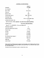
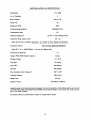
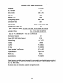
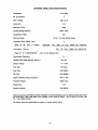
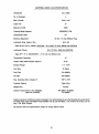
UNIVERSAL M-12 SPECIFICATIONS
Model 12
Horsepower
10
@
No. of Cylinders
2
Bore x Stroke
2.52 x 2.45 in.
Cubic Inch
25
Maximum R.P.M.
3600
Cruising Range (Approx.)
2600 - 3300 R.P.M.
Compression Ratio
23:1
Electrical Equipment
12 Volt - 51 Amp WIGlow Plugs
Lubrication (Eng. Approx. Qts.)
(SAE 30 HD. (CD) or 1OW40) CAUTION:
Lubrication (Trans.)
3600
1.5 - 2.0
FILL ONLY TO FULL MARK ON DIPSTICK
FILL TO FULL RING ON DIPSTICK
(Type AFT. oW' or GM-DEXRON - II Do not mix different oils)
2:1
Transmission Reduction
2.3 Qts.
Coolant FWC (50/50 Solution Approx.)
Exhaust Flange
1 Y4" N.P.T.
Fuel Type
#2 Diesel
Fuel Filter
PIN 298854
Oil Filter
PIN 300209
Eng. Operating Temp. Degrees F.
1650 to 1950
Propeller Rotation
Right Hand
Weight (Ibs.)
1751bs.
Injection Nozzle
PIN 301302
Engine is governor controlled to prevent overspeed. It is recommended to carry the following extra parts should
the need arise: V-Belt, Sea Water Pump Impeller, Fuel & Lube Oil Filters, 1 at. of Trans. Oil, 2 Qts. LUb. Oil
and 1 Gal. 50/50 Coolant.
All pictorial views and specifications subject to change without notice.
44
UNIVERSAL MODEL M,-12
THERMOSTAT HSG.
FUEL RETURN
FUEL FILTER
(AIR BLEED ON TOP)
FUEL AIR BLEED VALVE
SEA WATER
TO EXHAUST
::-----STOP LEVER
CLEAN OUT COVER--_ _--:::A
TRANS. DIP STICK &
OIL FILL HOLE
---~~
g""",,,,n
ENGINE COUPLI
COOLANT DRAIN '
~OILPAN
BELL HSG.
TIMING PORT
OIL DRAIN
IMANIFOLD
COOLANT FILL CAP
COOLANT BLEED VALVE
TEMP. SENDER
FLANGE
-----,;:Q
MANIFOLD DRAIN
F.W. CIRCULATING - - PUMP
~_-- HEAT
SEA WATER---PUMP
EXCHANGER
DRAIN & ZINC
PANEL PWG
STARTER SOLENOID
STARTER
45
UNIVERSAL M2-12 SPECIFICATIONS
M2-12
11
Horsepower
@
No. of Cylinders
2
Bore x Stroke
2.6 x 2.45 in
Cubic Inch
26
Maximum R.P.M.
3600
2600 - 3300 R.P.M.
Cruising Range (Approx.)
23:1
Compression Ratio
12 Volt - 51 Amp WIGlow Plugs
Electrical Equipment
1.5 - 2.0
Lubrication (Eng. Approx. Qts.)
(SAE 30 HD. (CD) or 10W40) CAUTION:
Lubrication (Trans.)
3600
FILL ONLY TO FULL MARK ON DIPSTICK
FILL TO FULL RING ON DIPSTICK
(Type AFT. "A" or GM-DEXRON® - II Do not mix different oils)
Transmission Reduction
2:1
Coolant FWC (50/50 Solution Approx.)
2.3 Qts.
1 V4" N.P.T.
Exhaust Flange
Fuel Type
#2 Diesel
Fuel Filter
PIN 298854
Oil Filter
PIN 300209
Eng. Operating Temp. Degrees F.
Right Hand
Propeller Rotation
1751bs.
Weight (Ibs.)
PIN 302735
Injection Nozzle
Engine is governor controlled to prevent overspeed. It is recommended to carry the following extra parts should
the need arise: V-Belt, Sea Water Pump Impeller, Fuel & Lube Oil Filters, 1 Qt. of Trans. Oil, 2 Qts. Lub. Oil
and 1 Gal. 50/50 Coolant.
All pictorial views and specifications subject to change without notice.
46
UNIVERSAL MODEL M2-12
GLOW PWGS
FUEL LINES
THERMOSTAT HSG.
FUEL RETURN
FUEL FILTER
(AIR BLEED ON TOP)
SEA WATER
TO EXHAUST
LEVER
CLEAN OUT COVER
TRANS. DIP STICK &
OIL FILL HOLE
---_::::x
---=
THROTTLE
g~"",n.
TRANS. DRAIN
(OPPOSITE SIDE)
~OILPAN
BELL HSG.
TIMING PORT
COOLANT FILL CAP
COOLANT BLEED VALVE
TEMP. SENDER
COOLANT DRAIN
OIL DRAIN
MANIFOLD
/
-----.(:'£1
F.W. CIRCULATING - - PUMP
~_-.
SEA WATER----,
PUMP
HEAT EXCHANGER
DRAIN & ZINC
PANEL PWG
V-BELT
MOUNTS
STARTER
47
UNIVERSAL MODEL M-15 SPECIFICATIONS
l:i0rsepower
11 @ 3000
No. of Cylinders
2
Bore x Stroke
2.68 x 2.76
Cubic Inch
31
Maximum R.P.M.
3000
Cruising Range (Approx.)
210012600 R.P.M.
Compression Ratio
22:1
12 Volt - 51 Amp WIG low Plugs
Electrical Equipment
Lubrication (Eng. Approx. ats.)
(SAE 30 HD. (CD) or 10W40) CAUTION:
2.5
FILL ONLY TO FULL MARK ON DIPSTICK
Lubrication (Trans.)
FILL TO FULL RING ON DIPSTICK
(Type AFT. "/1\' or GM-DEXRON - " Do not mix different oils)
Transmission Reduction
2:1
Coolant FWC (50/50 Solution Approx.)
Sea Water Cooled
1 Y4" N.P.T.
Exhaust Flange
Fuel Type
#2 Diesel
Fuel Filter
PIN 298854
Oil Filter
PIN 299381
Eng. Operating Temp. Degrees F.
Propeller Rotation
Right Hand
Weight (Ibs.)
245 Ibs.
Injection Nozzle
PIN 299517 &299518
Engine is governor controlled to prevent overspeed. It is recommended to carry the following extra parts should
the need arise: V-Belt, Sea Water Pump Impeller, Fuel & Lube Oil Filters, 1 Qt. of Trans. Oil, 2 Qts. LUb. Oil
and 1 Gal. 50/50 Coolant.
All pictorial views and specifications subject to change without notice.
Use pictOrial view M-18 or M-15 for parts locations.
48
UNIVERSAL MODEL M-15
FUEL LINES
OIL FILL CAP
GLOW PLUGS
FUEL RETUR
THERMOSTAT HSG.
FUEL FILTER
(BLEED ON TOP)
FUEL AIR BLEED VALVE
SEA WATER
TO EXHAUST
STOP LEVER
THROTTLE
TRANSMISSION ............
BLOCK COOLANT DRAIN
SHIFT LEVER
TIMING PORT
DECOM PRESSION LEVER
COOLANT AIR BLEED
TEMP. SENDER
\
BY·PASS HOSE
EXHAUST DRAIN
HEAT EXCHANGER
SEA WATER
PUMP - - -
PANEL PLUG
ALTERNATOR
TRANS. DIP STICK &
OIL FILL HOLE
V·BELT
"",--"",,,GINE COUPLING
:....--TRANS. DRAIN
OIL PAN
OIL DRAIN HOSE
49
UNIVERSAL MODEL M-18 SPECIFICATIONS
14 @ 3200
Horsepower
2
No. of Cylinders
Bore x Stroke
2.60 x 2.45
Cubic Inch
35
Maximum R.P.M.
3200
2100/2600 R. P. M.
Cruising Range (Approx.)
21:1
Compression Ratio
12 Volt - 51 Amp WIGlow Plugs
Electrical Equipment
2.5 - 3.0
Lubrication (Eng. Approx. Qts.)
(SAE 30 HD. (CD) or 10W40) CAUTION:
Lubrication (Trans.)
FILL ONLY TO FULL MARK ON DIPSTICK
FILL TO FULL RING ON DIPSTICK
(Type AFT. "p,:' or GM-DEXRON - " Do not mix different oils)
2:1
Transmission Reduction
3.0 qts.
Coolant FWC (50/50 Solution Approx.)
1 114" N.P.T.
Exhaust Flange
Fuel Type
#2 Diesel
Fuel Filter
PIN 298854
Oil Filter
PIN 300209
Eng. Operating Temp. Degrees F.
Right Hand
Propeller Rotation
2551bs.
Weight (Ibs.)
PIN 299517
Injection Nozzle
&299518
Engine is governor controlled to prevent overspeed. It is recommended to carry the following extra parts should
the need arise: V-Belt, Sea Water Pump Impeller, Fuel & Lube Oil Filters, 1 Qt. of Trans. Oil, 2 Qts. Lub. Oil
and 1 Gal. 50/50 Coolant.
All pictorial views and specifications subject to change without notice.
50
UNIVERSAL MODEL M·18
OIL FILL CAP
THERMOSTAT HSG.
FUEL FILTER
(BLEED ON TOP)
FUEL AIR BLEED VALVE
SEA WATER
TO EXHAUST
P LEVER
THROTTLE
TRANSMISSION
............
BLOCK COOLANT DRAIN
SHIFT LEVER
TIMING PORT
DECOMPRESSION LEVER
COOLANT AIR BLEED
TEMP. SENDER
.
~.
\
BY·PASS HOSE
EXHAUST DRAIN
HEAT EXCHANGER
SEA WATER
PUMP - - -
PANEL PLUG
DRAIN & ZINC
ALTERNATOR
TRANS. DIP STICK &
OIL FILL HOLE
V·BELT
m - - ..
",GINE COUPLING
_=---TRANS. DRAIN
ARTER SOLENOID
OIL PAN
OIL DRAIN HOSE
51
UNIVERSAL MODEL M-20 SPECIFICATIONS
Horsepower
16 @ 2800
No. of Cylinders
2
Bore x Stroke
2.68 x 2.76
Cubic Inch
45
Maximum R.P.M.
2800
Cruising Range (Approx.)
2000/2400 R.P.M.
Compression Ratio
21:1
Electrical Equipment
12 Volt - 51 Amp WIGlow Plugs
Lubrication (Eng. Approx. Ots.)
(SAE 30 HD. (CD) or 10W40) CAUTION:
Lubrication (Trans.)
4.0
FILL ONLY 10 FULL MARK ON DIPSTICK
FILL 10 FULL RING ON DIPSTICK
(Type AFT. "/1\' or GM-DEXRON - II Do not mix different oils)
Transmission Reduction
2:1
Coolant FWC (50/50 Solution Approx.)
5 qts.
1 V4" N.P.T.
Exhaust Flange
Fuel Type
#2 Diesel
Fuel Filter
PIN 298854
Oil Filter
PIN 298852
Eng. Operating Temp. Degrees F.
Propeller Rotation
Right Hand
Weight (Ibs.)
3651bs.
Injection Nozzle
PIN 298787 & 298788
Engine is governor controlled to prevent overspeed. It is recommended to carry the following extra parts should
the need arise: V-Belt, Sea Water Pump Impeller, Fuel & Lube Oil Filters, 1 Ot. of Trans. Oil, 2 Ots. Lub. Oil
and 1 Gal. 50/50 Coolant.
All pictorial views and specifications to change without notice.
Use pictorial view M-40 or M-20 for parts locations.
52
UNIVERSAL MODEL M-20
FUEL LINES
AIR BREATHER
FUEL RETURN
GLOWP~u,~~-
_ _ _ _ _~
FUEL AIR
D VALVE
SEA WATER OVERBOARD
---THROTTLE
HEAT EX. DRAIN & ZINC
- - - STOP LEVER
TRANS. DIP STICK &
OIL FILL HOLE - - SHIFT LEVER
' - - - - OIL FILTER
BLOCK COOLANT DRAIN
ENGINE COUPLING/
TIMING PORT
COOLANT AIR BLEED VALVE
COOLANT FILL CAP
MANIFOLD
THERMOSTAT
REGULATOR
EXHAUST FLANGE
/
F.W. CIRCULATING
PUMP - - -
MANIFOLD DRAIN
HEAT EXCHANGER
HEAT EX. CLEAN·OUT
COVERS
ALTERNATOR
SEA WATER PUMP
DRAIN AND ZINC
. DRAIN PLUG
OIL PAN
DIP STICK
53
UNIVERSAL MODEL M3-20 SPECIFICATIONS
Horsepower
18 @ 3600
No. of Cylinders
3
2.60 x 2.45
Bore x Stroke
Cubic Inch
38.9
Maximum R.P.M.
3600
Cruising Range (Approx.)
2600 - 3300
23:1
Compression Ratio
12 Volt - 51 Amp WIGlow Plugs
Electrical Equip.
Lubrication (Eng. Approx. Qts.)
3.2
(SAE 30 HD. (CD) or 10W40) CAUTION:
FILL 10 FULL RING ON DIPSTICK
Lubrication (Trans.)
(Type Aft. "N' or GM-DEXRON
FILL ONLY 10 FULL MARK ON DIPSTICK
®
- II Do not mix different oils)
Transmission Reduction
2:1
3 Qts.
Coolant FWC (50/50 Solution Approx.)
1 1/4" N.P.T.
Exhaust Flange
Fuel Type
#2 Diesel
Fuel Filter
PIN 298854
Oil Filter
PIN 300209
Engine Operating Temp. Degrees F.
Right Hand
Propeller Rotation
2351bs.
Weight (Ibs.)
Injection Nozzles
PIN 302735
Engine is governor controlled to prevent overspeecl. It is recommended to carry the following extra parts should
the need arise: V-Belt, Sea Water Pump Impeller, Fuel & Lube Oil Filters, 1 Qt. of Trans. Oil, 2 Qts. Lube
Oil, 1 Gal. 50/50 Coolant.
All pictorial views and specifications subject to change without notice.
54
UNIVERSAL MODEL M3-20
OIL FILL CAP
GLOW PWGS
\
FUEL RETURN
THERMOSTAT HSG.
AIR BREATHER
FUEL AIR BLEED VALVE
SEA WATER
TO EXHAUST
;;L----liiTCJP LEVER
CLEAN OUT COVER
TRANS. DIP STICK & _ _-""':",
OIL FILL HOLE
THROTTLE
TRANSMISSION
DIP STICK
ENGINE COUPLING
DL.".I",n
COOLANT DRAIN
BELL HSG.
COOLANT FILL CAP
MANIFOLD
/
COOLANT BLEED VALVE~ ..
TEMP. SENDER
MANIFOLD DRAIN
F.W. CIRCULATING
PUMP
--''''_'·n~ ...
PWG
_ _-nel\. EXCHANGER
SEA WATER
PUMP
DRAIN & ZINC
\
STARTER SOLENOID
STARTER
55
FLEX MOUNTS
UNIVERSAL MODEL M-25 SPECIFICATIONS
Horsepower
21
@
No. of Cylinders
3
Bore x Stroke
2.83 x 2.76
Cubic Inch
52
Maximum R.P.M.
3000
Cruising Range (Approx.)
210012600 R.P.M.
Compression Ratio
21:1
Electrical Equipment
12 Volt - 51 Amp WIG low Plugs
Lubrication (Eng. Approx. Qts.)
(SAE 30 HD. (CD) or 10W40) CAUTION:
3200
4.0
FILL ONLY TO FULL MARK ON DIPSTICK
Lubrication (Trans.)
FILL TO FULL RING ON DIPSTICK
(Type AFT. "p,:' or GM-DEXRON - II Do not mix different oils)
Transmission Reduction
2:1
Coolant FWC( 50/50 Solution Approx.)
5 qts.
Exhaust Range
1 Y4" N.P.T.
Fuel Type
#2 Diesel
Fuel Filter
PIN 298854
Oil Filter
PIN 300209
Eng. Operating Temp. Degrees F.
Propeller Rotation
Right Hand
Weight (Ibs.
285 Ibs.)
Injection Nozzle
PIN 299517 & 299518
Engine is governor controlled to prevent overspeed. It is recommended to carry the following extra parts should
the need arise: V-Belt, Sea Water Pump Impeller, Fuel & Lube Oil Filters, 1 Qt. of Trans. Oil, 2 Ots. Lub. Oil
and 1 Gal. 50/50 Coolant.
All pictorial views and specifications subject to change without notice.
56
UNIVERSAL MODEL M-25
AIR BREATHER
NJECTOR PUMP
FUEL RETURN
INJ. PUMP BLEED
EXHAUST FLANGE
GLOW PLUGS - - - - - :
THROTTLE
CLEAN OUT
DIP STICK
LOCK COOLANT
DRAIN
TIMING PORT
BELL HOUSING
OIL DRAIN HOSE
FUEL FILTER
(AIR BLEED ON TOP OF FILTER)
COOLANT AIR BLEED-_ _ """,
MANIFOLD
TEMP. SENDER-MANIFOLD DRAIN
HEAT EXCHANGER
F.W. CIRCULATING
PUMP
PANEL PLUG
SEA WATER
PUMP
DRAIN & ZINC
ALTERNATOR
-
STARTER SOLENOID
OIL FILTER
TRANSMISSION
TRANS. DRAIN PLUG
REGULATOR
57
UNIVERSAL MODEL M-25XP SPECIFICATIONS (UPDATE OF M-25)
Horsepower
23
@
No. of Cylinders
3200
3
Bore x Stroke
2.95 x 2.76
Cubic Inch
56.6
Maximum R.P.M.
3200
Cruising Range (Approx.)
2100/2600 R.P.M.
Compression Ratio
21:1
Electrical Equipment
12 Volt - 51 Amp WIG low Plugs
Lubrication (Eng. Approx. Ots.)
(SAE 30 HD.(CD) or 10W40) CAUTION:
4.0 to 4.3
FILL ONLY TO FULL MARK ON DIPSTICK
Lubrication (Trans.)
FILL TO FULL RING ON DIPSTICK
(Type AFT. ''/1\' or GM-DEXRON - " Do not mix different oils)
2:1
Transmission Reduction
Coolant FWC (50/50 Solution Approx.)
5 qts.
1 1/4" N.P.T.
Exhaust Flange
Fuel Type
#2 Diesel
Fuel Filter
PIN 298854
Oil Filter
PIN 300209
Eng. Operating Temp. Degrees F.
Right Hand
Propeller Rotation
2851bs.
Weight (Ibs.)
PIN 299517
Injection Nozzle
&299518
Engine is governor controlled to prevent overspeed. It is recommended to carry the following extra parts should
the need arise: V-Belt, Sea Water Pump Impeller, Fuel & Lube Oil Filters, 1 at. of Trans. Oil, 2 ats. Lub. Oil
and 1 Gal. 50/50 Coolant.
All pictorial views and specifications subject to change without notice.
58
UNIVERSAL MODEL M-2SXP
OIL FILL CAP
THERMOSTAT HSG.
AIR BREATHER
FUEL FILTER
(AIR BLEED ON TOP)
FUEL AIR BLEED VALVE
SEA WATER
TO EXHAUST
_ - - - - STOP LEVER
THROTTLE
DIP STICK
......... vn.
COOLANT DRAIN
COOLANT BLEED VALVE
TEMP. SENDER -
_ _ __
BY·PASS HOSE
IFOLD DRAIN
F.W.
PANEL PWG
---HEAT EXCHANGER
SEA WATER
PUMP
---DRAIN & ZINC
MOUNTS
STARTER
59
UNIVERSAL MODEL M4-30 SPECIFICATIONS
Horsepower
25
@
No. of Cylinders
3600
4
Bore x Stroke
2.60 x 2.45
Cubic Inch
51.9
Maximum R.P.M.
3600
Cruising Range (Approx.)
2600 - 3300
Compression Ratio
23:1
Electrical Equip.
12 Volt - 51 Amp WIGlow Plugs
Lubrication (Eng. Approx. Ots.)
4
(SAE) 30 HD. (CD) or 10W40) -
CAUTION:
Lubrication (Trans.)
(Type Aft. "1\' or GM-DEXRON
FILL ONLY TO FULL MARK ON DIPSTICK
FILL TO FULL RING ON DIPSTICK
®
- II Do not mix different oils)
Transmission Reduction
2:1
Coolant FWC (50/50 Solution Approx.)
3112 Ots.
1 114" N.P.T.
Exhaust Flange
Fuel Type
#2 Diesel
Fuel Filter
PIN 298854
011 Filter
PIN 300209
Engine Operating Temp. Degrees F.
Propeller Rotation
Right Hand
Weight (Ibs.)
270
Injection Nozzles
PIN 302735
Engine is governor controlled to prevent overspeed. It is recommended to carry the following extra parts should
the need arise: V-Belt, Sea Water Pump Impeller, Fuel & Lube Oil Filters, 1 at. of Trans. Oil, 2 Ots. Lube
Oil, 1 Gal. 50/50 Coolant.
All pictorial views and specifications subject to change without notice.
60
UNIVERSAL MODEL M4-30
OIL FILL CAP
GLOW PWGS
FUEL LINES
THERMOSTAT HSG.
R BREATHER
FUEL FILTER
(AIR BLEED ON TOP)
AIR BLEED VALVE
SEA WATER
TO EXHAUST
~_--STOP
LEVER
CLEAN OUT COVER
TRANS. DIP STICK & _ __
OIL FILL HOLE
----THROTTLE
DIP STICK
DL""~~
ENGINE COUPLING
COOLANT DRAIN
BELL HSG.
COOLANT FILL CAP
COOLANT BLEED VALVE
FLANGE
TEMP. SENDER
F.W. CIRCULATING
PUMP - - - - - - - - " l
PANEL PWG
---HEAT EXCHANGER
SEA WATER----·
PUMP
- - DRAIN & ZINC
FLEX MOUNTS
STARTER SOLENOID
STARTER
61
UNIVERSAL MODEL M-30 SPECIFICATIONS
Horsepower
24 @ 2800
No. of Cylinders
3
Bore x Stroke
3.00 x 3.23
Cubic Inch
68
Maximum R.P.M.
2800
Cruising Range (Approx.)
2000-2400 R.P.M.
Compression Ratio
21:1
12 Volt - 51 Amp WIG low Plugs
Electrical Equipment
Lubrication (Eng. Approx. Qts)
(SAE 30 HD. (CD) or 10W40) CAUTION:
Lubrication (Trans.)
5.0 to 5.5
FILL ONLY TO FULL MARK ON DIPSTICK
FILL TO FULL RING ON DIPSTICK
(Type AFT. "/{' or GM-DEXRON - II Do not mix different oils)
Transmission Reduction
2:1
Coolant FWC (50/50 Solution Approx.)
6 qts.
1 Y4" N.P.T.
Exhaust Flange
Fuel Type
#2 Diesel
Fuel Filter
PIN 298854
Oil Filter
PIN 300209
Eng. Operating Temp. Degrees F.
Propeller Rotation
Right Hand
Weight (Ibs.)
4251bs.
PIN 298787 & 298788
Injection Nozzle
Engine is governor controlled to prevent overspeed. It is recommended to carry the following extra parts should
the need arise: V-Belt, Sea Water Pump Impeller, Fuel & Lube Oil Filters, 1 at. of Trans. Oil, 2 ats. Lub. Oil
and 1 Gal. 50/50 Coolant.
All pictorial views and speCifications subject to change without notice.
Use pictorial view M-40 for parts locations.
62
UNIVERSAL MODEL M-30
FUEL LINES
AIR BREATHER
FUEL RETURN
GLOWPLu\~~---
________~
---....
SEA WATER OVERBOARD
FUEL AIR
VALVE
---THROTTLE
- - STOP LEVER
HEAT EX. DRAIN & ZIN
TRANS. DIP STICK
OIL FILL HOLE - - SHIFT LEVER
'----OIL FILTER
ENGINE COUPLING/
TIMING PORT
COOLANT AIR BLEED VALVE
COOLANT FILL CAP
MANIFOLD
THERMOSTAT
ST FLANGE
ANIFOLD DRAIN
HEAT EXCHANGER
F.W. CIRCULATING
PUMP - - -
HEAT EX. CLEAN·OUT
COVERS
ALTERNATOR
SEA WATER PUMP
- - - DRAIN AND ZINC
TRANSMISSION
S. DRAIN PLUG
OIL PAN
DIP STICK
63
UNIVERSAL MODEL M-35 SPECIFICATIONS
Horsepower
30
@
No. of Cylinders
3200
4
Bore x Stroke
2.96 x 2.76
Cubic Inch
75.5
Maximum R.P.M.
3200
Cruising Range (Approx.)
2100-2600 R.P.M.
Compression Ratio
21:1
Electrical Equipment
12 Volt - 51 Amp W/Glow Plugs
Lubrication (Eng. Approx. Qts.)
(SAE 30 HD. (CD) or 10W40) CAUTION:
4.5 to 5.0
FILL ONLY 10 FULL MARK ON DIPSTICK
Lubrication (Trans.)
FILL 10 FULL RING ON DIPSTICK
(Type AFT. "I{' or GM-DEXRON - II Do not mix different oils)
Transmission Reduction
2:1
Coolant FWC (50/50 Solution Approx.)
5 qts.
1 Y4" N.P.T.
Exhaust Flange
Fuel Type
#2 Diesel
Fuel Filter
PIN 298854
Oil Filter
PIN 300209
Eng. Operating Temp. Degrees F.
165Ofo 1950
Propeller Rotation
Right Hand
Weight (Ibs.)
3351bs.
Injection Nozzle
PIN 299517 &299518
Engine is governor controlled to prevent overspeed. It is recommended to carry the following extra parts should
the need arise: V-Belt, Sea Water Pump Impeller, Fuel & Lube Oil Filters, 1 Qt. of Trans. Oil, 2 Ots. Lub. Oil
and 1 Gal. 50/50 Coolant.
All pictorial views and specifications subject to change without notice.
64
UNIVERSAL MODEL M·35
OIL FILL CAP
THERMOSTAT HOUSING
INJ
BY·PASS HOSE
GLOW PLUGS
SALT WATER TO
EXHAUST
FUEL AIR BLEED VALVE
CLEAN OUT
COVERS
STOP LEVER
----THROTTLE
TRANS. DIP STICK &
OIL FILL HOLE
LOCK COOLANT DRAIN
SHIFT LEVER
------FLEX MOUNTS
TRANSMISSION
FUEL FILTER
(AIR BLEED ON TOP)
BELL HOUSING
COOLANT FILL CAP
FUEL LINES
TEMP.SENDERS~
F.W. CIRCULATING
PUMP
MANIFOLD DRAIN
SEA WATER--PUMP
HEAT EXCHANGER
ALTERNATOR
ENGINE COUPLING.
~TRANS
OIL FILTER
OIL DRAIN
HOSE
STARTER SOLENOID
OIL PAN
65
DRAIN
UNIVERSAL MODEL M-40 SPECIFICATIONS
Horsepower
32
2800
@
No. of Cylinders
4
Bore x Stroke
3.00
Cubic Inch
x 3.23
91
Maximum R.P.M.
2800
Cruising Range (Approx.)
2000/2500 R.P.M.
Compression Ratio
21:1
Electrical Equipment
12 Volt - 51 Amp WIG low Plugs
ao to 8.5
Lubrication (Eng. Approx. Qts.)
(SAE 30 HD. (CD) or 1OW40) CAUTION: FILL ONLY 10 FULL MARK ON DIPSTICK
Lubrication (Trans.)
(Type AFT. "A" or GM-DEXRON -
FILL 10 FULL RING ON DIPSTICK
II Do not mix different oils)
Transmission Reduction
2:1
Coolant FWC (50/50 Solution Approx.)
8 qts.
Exhaust Flange
Fuel Type
#2 Diesel
Fuel Filter
PIN 298854
Oil Filter
PIN 299927
Eng. Operating Temp. Degrees F.
Right Hand
Propeller Rotation
Weight (Ibs.)
545lbs.
Injection Nozzle (Prior to Ser. #315023)
(After Ser. #315023)
PIN 299517 &299518
PIN 299567
Engine is governor controlled to prevent overspeed. It is recommended to carry the following extra parts should
the need arise: V-belt, Sea Water Pump Impeller, Fuel & Lube Oil Filters, 1 Qt. of Trans. Oil, 2 Ots. Lub. Oil
and 1 Gal. 50/50 Coolant.
All pictorial views and specifications subject to change without notice.
66
UNIVERSAL MODEL M·40
FUEL LINES
AIR BREATHER
FUEL RETURN
FUEL AIR
LEED VALVE
GLOW PLUGS-_ _ _ __
'----TH ROTTLE
STOP LEVER
HEAT EX. DRAIN & ZI
TRANS. DIP STICK
OIL FILL HOLE
'----OIL FILTER
SHIFT LEVER
BLOCK COOLANT DRAIN
ENGINE COUPLING/
TIMING PORT
COOLANT- AIR BLEED VALVE
COOLANT FILL CAP
THERMOSTAT HSG.
ST FLANGE
IFOLD DRAIN
F.W. CIRCULATING
PUMP - - -
HEAT EX. CLEAN·OUT
COVERS
ALTERNATOR
SEA WATER PUMP
----DRAIN AND ZINC
TRANSMISSION
V·BELT
. DRAIN PLUG
OIL PAN
DIP STICK
67
UNIVERSAL MODEL M-50 SPECIFICATIONS
Horsepower
44
@
No. of Cylinders
4
Bore x Stroke
3.35 x 3.23
Cubic Inch
115
Maximum R.P.M.
3000
Cruising Range (Approx.)
2000/2500 R.P.M.
Compression Ratio
21:1
Electrical Equipment
12 Volt - 51 Amp WIG low Plugs
Lubrication (Eng. Approx. Qts.)
(SAE 30 HD. (CD) or 10W40) CAUTION:
Lubrication (Trans.)
3000
8.5
FILL ONLY TO FULL MARK ON DIPSTICK
FILL TO FULL RING ON DIPSTICK
Transmission Reduction
1.9:1
Coolant FWC (50/50 Solution Approx.)
8 qts.
Exhaust Flange
1 V4" N.P.T.
Fuel Type
#2 Diesel
Fuel Filter
PIN 298854
Oil Filter
PIN 299927
Eng. Operating Temp. Degrees F.
1650 to 1950
Propeller Rotation
Right Hand
Weight (Ibs.)
545 Ibs.
Injection Nozzle
PIN 299567
Engine is governor controlled to prevent overspeed. It is recommended to carry the following extra parts should
the need arise: V-Belt, Sea Water Pump Impeller, Fuel & Lube Oil Filters, 1 Qt. of Trans. Oil, 2 Qts. Lub. Oil
and 1 Gal. of 50/50 Coolant.
All pictorial views and specifications subject to change without notice.
68
UNIVERSAL MODEL M-50
FUEL LINES
INJECTORS
AIR BREATHER
FUEL RETURN
FUEL AIR
LEED VALVE
GLOW PLUGS--_ _ _---.J
SEA WATER OVERBOARD
HEAT EX. DRAIN & ZINC_
' - - - STOP LEVER
TRANS. DIP STICK
OIL FILL HOLE - - - - O I L FILTER
BLOCK COOLANT DRAIN
ENGINE COUPLING/
MOUNTS
TIMING PORT
COOLANT AIR BLEED VALVE
COOLANT FILL CAP
/
THERMOSTAT HSG.
MANIFOLD
ANI FOLD DRAIN
HEAT EXCHANGER
F.W. CIRCULATING
PUMP - - - :
HEAT EX. CLEAN·OUT
COVERS
ALTERNATOR
SEA WATER PUMP ----.
----- DRAIN AND ZINC
TRANSMISSION
V·BELT
. DRAIN PLUG
STARTER
OIL PAN
DIP STICK
69
PROGRAMMABLE TACHOMETER WI HOURMETER
On the back of the tachometer there is an over/shaped black plug. Upon removal of the plug, fourteen
switches will be visible. The switches are divided into two sections. The program must be entered from
left to right, i.e., switch position 1 is the left most number. Down represents an OFF position and UP
represents an ON position. Please refer to your model for proper setting.
(SETTINGS AS VIEWED FROM BACK OF TACH)
MODELS -
~1~ 3
o
M2-12
4 5ffi2
M3-20
M4-30
3~4
5 6 7 8
1 ~ ~bid
!
~~-
o
BACK OF TACH
GND
MODELS -
M-25XP
SEND
M-35
P(3~456]
o l_~BACK OF TACH
GND
MODELS -
o
GND
M-40
SEND
M-50
~1 2 3 4~5
6 ~ 2 3 4 5 ~7
8
1~~_
l
o
_
M
BACK OF TACH
SEE OTHER SIDE FOR MORE MODELS
o
SEND
MODELS -
M-15
M-18
o.I~
GND
BACK OF TACH
MODELS -
o
GND
M-20
SEND
M-30
~45~6~23456~
lI~~~___
_
WD<J
BACK OF TACH
MODEL -
o
o
SEND
M-25
~234~4567~8
o
GND
I1 ==kkbd~
_
_ _ ~~D<J
BACK OF TACH
o
SEND