1
Brother Laser Printer
HL-Series
Technical Reference Guide
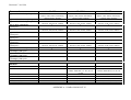
Revision A
Revision B
December, 1993
January, 1994
Revision C
October, 1994
Addition of Appendix A "Comparison list
for some models"
Addition of the model HL-660/HL-1260
Copyright © 1993 - 1994
Brother Industries Ltd.
ALL RIGHTS RESERVED
Trademark acknowledgments
Brother is a registered trademark and Twinriter a trademark of Brother Industries Ltd.
PostScript is a registered trademark of Adobe Incorporated.
Epson is a registered trademark and FX-850 a trademark of Seiko Epson Corporation.
Hewlett Packard, HP, LaserJet and PCL are registered trademarks and LaserJet 4, HP-GL, and HP-GL/2 are
trademarks of Hewlett Packard Company.
IBM is a registered trademark and Proprinter XL is a trademark of International Business Machines
Corporation.
Microsoft and MS-DOS are registered trademarks, Windows is a trademark of Microsoft Corporation and.
Diablo and Diablo 630 are trademarks of Xerox Corporation.
Intellifont is a registered trademark of Agfa Corporation.
TrueType is a trademark of Apple Computer, Inc.
All other brand and product names mentioned in this manual are registered trademarks or trademarks of
respective companies.
Compilation and Publication
Under the supervision of Brother Industries Ltd., this manual has been compiled and published, covering the
latest product's descriptions and specifications.
The contents of this manual and the specifications of this product are subjected to change without notice.
Brother reserves the right to make changes without notice in the specifications and materials contained herein
and shall not be responsible for any damages (including consequential) caused by reliance on the materials
presented, including but not limited to typographical and other errors relating to the publication.
Contents
Glossary
Chapter 1 - Introduction to the HL Series Laser printer
DESCRIPTION OF THE PRINTER
ABOUT THE MANUAL
AREAS OF USE
Using word-processing packages and spreadsheets
Graphics
Programming
2
2
2
2
3
3
Chapter 2 - PCL
COMMAND LIST
INTRODUCTION
CONTROLLING THE PRINTER
ENVIRONMENTS
JOB CONTROL
THE PAGE
USING FONTS
USING GRAPHICS
MACRO
STATUS READBACK
2
5
6
9
10
15
32
68
89
95
Chapter 3 - PJL , Printer Job Language
INTRODUCTION
PJL SYNTAX AND FORMAT
HOW TO USE PJL
KERNEL COMMANDS
JOB SEPARATION COMMANDS
ENVIRONMENT COMMANDS
STATUS READBACK COMMAND
DEVICE ATTENDANCE COMMANDS
2
4
8
10
14
17
33
52
Chapter 4 - Diablo 630
COMMAND LIST
INTRODUCTION
EMULATION DETAILS
TERMINOLOGY
CONTROLLING THE PRINTER
COMMANDS
2
3
3
4
4
6
Chapter 5 EPSON FX-850
COMMAND LIST
INTRODUCTION
EMULATION DETAILS
TERMINOLOGY
CONTROLLING THE PRINTER
COMMANDS
Chapter 6 IBM Proprinter XL
2
4
4
5
5
7
COMMAND LIST
INTRODUCTION
EMULATION DETAILS
NOTATION USED IN THIS EMULATION DESCRIPTION
COMMANDS
2
4
4
5
5
Chapter 7 - Barcode Control
Chapter 8 - HP-GL/2
TABLE OF CONTENTS
INTRODUCTION
TERMINOLOGY
COMMAND SYNTAX
THE HP-GL GRAPHICS WINDOW
PREPARING TO PRINT GRAPHICS IMAGES
COMMANDS
INITIALIZATION AND DEFAULT SETTING INSTRUCTIONS
PLOT AREA AND UNIT SETTING INSTRUCTIONS
PEN CONTROL AND PLOT INSTRUCTIONS
THE POLYGON GROUP
PLOT FUNCTION INSTRUCTIONS
CHARACTER PLOT INSTRUCTIONS
2
4
4
5
6
6
8
8
10
16
25
32
44
Chapter 9 - HP-GL
TABLE OF CONTENTS
INTRODUCTION
HP-GL SYNTAX
FONT SELECTION
COORDINATE SYSTEM AND PRINTING AREA
COORDINATE SYSTEM
printing AREA
COMMANDS
INITIALIZATION AND DEFAULT SETTING INSTRUCTIONS
PLOT AREA AND UNIT SETTING INSTRUCTIONS
PEN CONTROL AND PLOT INSTRUCTIONS
THE POLYGON GROUP
PLOT FUNCTION INSTRUCTIONS
CHARACTER PLOT INSTRUCTIONS
DUAL CONTEXT EXTENSIONS
USER RESET
FACTORY RESET
2
4
4
4
4
4
5
6
6
8
12
21
29
33
43
43
43
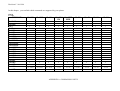
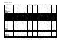
Appendix-A - Comparison list for
HL-660, HL-1260, HL-10h, HL-10V/DV, HL-10PS/DPS, HL-8V, HL-4V, HL-4Ve and HL-6V
Glossary
Absolute plotting
A method of plotting in the HP-GL and HP-GL/2 graphics language where
coordinates are specified relative to the origin of the coordinate system
currently in use.
Anchor point
The top left-hand corner of the PCL picture frame. You can position this on
the page using a PCL command.
Anisotropic scaling
A form of image scaling using the SC command in HP-GL and HP-GL/2
mode in which the user units can be of different sizes. Hence the entire
graphics window can be used to display the image.
ASCII
The standard system for assigning number codes (0 ~ 255) to alphabetic,
numeric and control code characters.
Attribute
A characteristic of a downloadable font or a character of a Downloadable font
that is represented by a number of a fixed length.
Bitmap font
A font whose characters are defined as raster images. The characters that
make up a bitmap font are of a fixed size.
Bold
A wider line thickness for typographical characters, used to make the text
stand out, for example, in headings.
Calling a macro
A way of running a macro in which changes to the modified print environment
are not retained when the macro has finished running.
Cartridge
A storage medium that you can insert into the printer cartridge slots.
Cartridges can store fonts. The advantage of using cartridges is that they
allow you to use more fonts without taking up printer memory space.
Cartridge font
A font that is stored on a cartridge. These are widely available commercially.
Character cell
The imaginary grid on which downloadable characters are designed.
Character code
A number assigned to a character that uniquely identifies it.
Character descriptor
A block of data that describes the characteristics of an individual character in
a downloadable font, such as its width and height.
Character set
A selection of different characters. Characters sets normally include the
alphabet in both upper- and lowercase, the digits' 0-9, punctuation marks,
common mathematical symbols and a few other useful characters. There are
also some specialized character sets that are used for specific applications like
mathematics. A font is defined as having a particular character set.
Column
A vertical sub-division of the page whose width is equal to the HMI
(horizontal motion index). The print position moves across the page one
column width when any single character is printed ( in a monospaced font),
or when a space character is printed ( in a proportionally spaced font). See
also HMI.
Control code
An ASCII code that tells the computer to perform a particular function, such
as a carriage return.
Control panel reset
A reset or factory reset performed using the printer control panel.
Cross-hatching
A method of shading using perpendicular diagonal lines that cross one
another.
Current units
The current unit type in use in HP-GL and HP-GL/2 mode. Current units are
either user units or graphics units depending on whether an SC command has
been used.
Cursor
Although the printer does not have a cursor, it is sometimes easier to visualize
the printer's operation in terms of a cursor that can be moved from place to
place on the page.
Cursor position
The current position of the imaginary cursor.
Decipoint
A unit of measure equal to 1/720".
Default conditions
A set of HP-GL and HP-GL/2 mode settings that you restore using the DF;
command. The default conditions are a subset of the initial settings.
Destination image
The graphic image that is already in place on a page and to which the source
image is applied in the LaserJet series print model.
Dots
A unit of measure equal to 1/600", the smallest increment that the cursor can
move.
Downloadable font
A character font that can be downloaded from your computer to the printer.
You can either buy Downloadable fonts or create your own. A downloadable
font consists of a font descriptor block followed by a character code,
character descriptor block and the data for each character in the font.
Downloading
The process of sending either a font, a macro or a graphic image from your
computer to the printer.
Effective window
The area of the page on which HP-GL and HP-GL/2 output can appear. The
effective window is determined by the overlap of the logical page, the PCL
picture frame, the hard clip and the soft clip limits.
Emulation mode
A mode of operation in which the printer imitates the functions of a different
model.
Enabling a macro for overlay
A macro that is enabled for overlay runs as the final operation before each
page is printed, using the macro overlay environment printer settings.
Escape sequence
The Esc character followed by a string of other characters that tell the printer
which operation to perform.
Factory default environment The collection of printer settings that have been made to the printer before it
leaves the factory. You can reset the printer to the factory settings either by
using a printer command or using the control panel.
Factory reset
A reset in which LaserJet mode is made the current emulation mode and the
factory default environment is restored.
Fill
A shading applied to a shape that you have drawn.
Fixed spacing
See monospacing.
Font
A collection of characters that are designed to work in harmony together. A
font has several characteristics that identify it uniquely: character or symbol
set, spacing, pitch, height or point size, style, stroke weight and typeface.
Fonts can either be resident in the printer's ROM, installed on cartridge or
downloaded from your computer. You can either buy downloadable fonts
commercially or create your own. The word "font" is often wrongly used to
mean "typeface". A font is confined to a single height or point size whereas a
typeface is not.
Font descriptor
A block of data that is downloaded to the printer as the first part of a
downloaded font. The font descriptor describes the characteristics that are
common to every character in the font, such as stroke weight, and contains
other relevant information.
Graphics mode initial settings
The HP-GL and HP-GL/2 mode settings that are in effect when you enter HPGL and HP-GL/2 mode. You can restore the initial conditions using the IN;
command.
Graphics units
The default units of the HP-GL and HP-GL/2 coordinate system. Also
sometimes called plotter units.
Graphics window
The area on the page in which HP-GL and HP-GL/2 graphic images can
appear. Initially this is the same as the picture frame, but you can change the
size, position and aspect ratio of the graphics window using the IW
command.
Gray scale
A degree of continuous shading ranging from 0%, very light gray, to 100%,
black.
Hard clip limits
The area of the page on which it is physically possible to print using HP-GL
and HP-GL/2 graphics language commands. The hard clip limits are
determined by the size of the physical page and are equivalent to the LaserJet
mode printable area.
Hatching
A method of shading using parallel lines.
Height
The height in typographic points (1/72") of an unaccented capital letter in a
font.
HMI
Horizontal motion index. The horizontal distance that the print position
moves across the page when any single character is printed ( in a monospaced
font ), or when a space character is printed ( in a proportionally spaced font
). You can set the HMI using printer commands, however, when you alter
any font characteristic ( in effect, select a new font ) or switch between the
primary and secondary fonts, the HMI is reset to its default value based on
the newly selected font.
Horizontal plot size
The original horizontal size of an imported HP-GL and HP-GL/2 image.
Internal font
A font that is stored in the printer ROM and is therefore always available for
use, for example, Brougham 10 pitch, or a font generated from a scalable
typeface stored in the printer's ROM, for example, Tennessee bold 15 pt.
Isotropic scaling
A form of image scaling using the SC command in HP-GL or HP-GL/2 mode
in which the user units must be of equal size. Hence it may not be possible to
use the entire graphics window to display the image.
Justification
The way in which text is aligned. For example, left justification involves
aligning the left end of every line of text.
Label
A text string that forms part of an HP-GL and HP-GL/2 plot.
Landscape
The orientation in which the top edge of the page is longer than the side edges.
Logical page
The area of the physical page on which the cursor can be positioned in
LaserJet mode. You can use PCL commands to specify the position of the
logical page on the physical page. Also known as the PCL addressable area.
LSB
i) The least significant byte of a set of data bytes.
ii) The least significant bit of a single byte of data.
Macro
A sequence of PCL commands that can be stored in the printer memory. To
run the sequence you need only use a single PCL command.
Macro execution
Executing a macro is a way of running a macro whereby any changes made to
the modified print environment by the macro are retained when macro
execution has been completed.
Macro overlay environment
Used only by a macro that has been enabled for overlay. A combination of
the user default environment and the modified print environment.
Medium
The line thickness of normal type.
Modified print environment
The collection of all current LaserJet printer settings. This environment is
saved if you call a macro or enter HP-GL and HP-GL/2 mode, and then
restored when the macro has finished running or when you quit HP-GL or
HP-GL/2 mode.
Monospacing
Some bitmap fonts are printed with each character occupying the same space
on a line of text. This is known as monospacing.
MSB
i) The most significant byte of a set of data bytes.
ii) The most significant bit of a single byte of data.
Pattern
i) The hatching or cross-hatching that can be applied to an outline shape.
ii) The non-white areas of the source image in the LaserJet print model.
Pattern transparency
The patterned ( non-white ) areas of the source image are either transparent,
in which case the destination image is visible through the white parts of the
pattern, or opaque, in which case the destination image is not visible at all
throughout the patterned areas of the source image.
PCL
Printer Control Language. The language consisting of escape sequences that
is used to control the printer in LaserJet mode
PCL addressable area
See logical page.
PCL picture frame
See picture frame.
Pen
Although this printer is a laser printer the HP-GL/2 and HP-GL graphics
languages retains the notion of a pen and allows you to select between two
pens, white and black. You must select a pen before you can draw anything.
The HP-GL and HP-GL/2 language were originally developed for use with
plotters and the terminology remains.
Perforation skip
A feature whereby the printer automatically compensates for a page break
and resumes printing from the top of the text area on the next page.
Permanent font
A downloaded font that is retained when a printer reset is performed.
Permanent macro
A macro stored in the printer that will not be erased if the printer is reset.
Physical page
The paper or envelope on which the printer prints.
Picture frame
The area of the physical page in which HP-GL and HP-GL/2 graphic images
can be printed.
Pitch
The number of characters in one inch of text. Only applicable to monospaced
(fixed pitch fonts.)
Plot
A drawing produced using the HP-GL and HP-GL/2 graphics language. So
called because the language was originally invented for use with plotters.
Plotter units
See graphics units.
Point
The standard unit of measurement for character height. Equal to 1/72".
Point factor scaling
A form of image scaling using the SC command in HP-GL or HP-GL/2 mode
in which the user units and the location of the scaling point P1 are specified in
terms of graphics units.
Point size
See height.
Polygon
A shape consisting of one or more closed groups of connected lines.
Polygon buffer
An area of printer memory in which you can store one or more polygons and
sub-polygons defined using HP-GL and HP-GL/2 commands. Some HP-GL
and HP-GL/2 commands use the polygon buffer automatically.
Portrait
The orientation in which the side edges of the page are longer than the top
edge.
Posture
A component of a font's style - whether it is upright or italic.
Primary font
In LaserJet mode the printer maintains two current font settings. The primary
font is the first of these.
Print model
A way of describing the interaction between different graphic elements (
source image, pattern and destination image ).
Printable area
The area of the page on which the printer can print.
Print position
The position from which printing of the next character or graphic object will
begin, providing that no operations that change the print position are
performed in the interim.
Proportional spacing
Fonts intended for high quality typographic output use a method of character
spacing in which the space occupied by a single character on a line of text
depends on the individual design of the character. This is known as
proportional spacing. Scalable fonts are almost invariably proportionally
spaced.
RAM
Random Access Memory. The printer's memory in which fonts and macros
can be stored and where pages that are to be printed are composed.
Raster graphics
A method of representing a graphic image as a series of zeroes and ones that
correspond to white and black dots respectively.
Relative plotting
A method of plotting in the HP-GL and HP-GL/2 graphics language where
coordinates are specified relative to the point at which the last graphics
command terminated.
Reset
When you reset the printer you restore a base set of conditions. A reset can
either be performed using the control panel or by sending the printer a reset
command. There are two types of reset, the normal reset and factory reset. A
normal reset simply restores the current emulation mode with the most recent
control panel settings -- it does not change the emulation mode itself. A
factory reset makes LaserJet mode the current emulation mode and restores
the factory default environment.
Resident font
See internal font.
ROM
Read Only Memory. Part of the printer's memory that contains the software
controlling the printer and the printer internal fonts. The ROM cannot be
altered.
Row
A horizontal sub-division of the page whose height is equal to the VMI
(vertical motion index). The print position moves down the page a distance
equal to the row height when a line feed is performed.
Sans serif
A kind of typeface normally used for headlines. Sans serif typefaces do not
have little hooks (serifs) on the individual characters. This helps Sans serif
headline text stand out more prominently.
Scalable fonts
A font for which you can specify the character size. The printer will
automatically scale the characters to the size you require.
Scaling
In HP-GL or HP-GL/2 mode you can use the SC command to scale graphic
images. The three types of scaling are known as anisotropic, isotropic and
point factor scaling.
Scaling points
Two imaginary points called P1 and P2 that define a rectangular area relative
to the picture frame. You can user the HP-GL or HP-GL/2 SC and IP or IR
commands to transform and scale images by changing the relationship
between the two scaling points.
Scalable typeface
A typeface for which you can choose a point size (height) in order to obtain a
particular font for printing. For example, you might select the Utah typeface
and then select 14 pt. as the height. The printer has many resident typefaces.
You can also buy scalable typeface cartridge and disks.
Secondary font
In LaserJet mode the printer maintains two current font settings. The
secondary font is the second of these.
Serif
A kind of typeface normally used for body text. Serif typefaces have little
hooks (serifs) on the individual characters that makes text more readable.
Soft clip limits
See graphics window. The soft limits are determined by the IW command.
Source image
The graphic image that is applied to the destination image in the LaserJet
print model. The interaction of the two images is determined by the current
source and pattern transparency settings.
Source transparency
The source image is either transparent, in which case the destination image is
visible throughout the white parts of the source image, or opaque, in which
case the destination image is not visible at all through the source image.
Spacing
The way in which a font's characters are arranged on a line of text. See
monospacing and proportional spacing.
Stick font
The default HP-GL and HP-GL/2 font consisting of thin lined characters.
Stroke weight
The thickness of the lines that comprise the characters in a particular font.
Medium, bold and light stroke weights are commonly used.
Sub-polygon
A shape consisting of a closed group of points connected by lines. Several
sub-polygons can form one polygon.
Symbol set
See character set.
Tab channel
A set of up to sixteen vertical tab stops. Up to eight vertical tab channels can
be set up in the Epson FX-850 mode.
Temporary font
A downloaded font that is erased from the printer's memory when a printer
reset is performed. To use the font again you must download it again.
Temporary macro
A macro that is erased from the printer's memory when a reset is performed.
If you want to use the macro again you must redefine it and download it to the
printer again.
Text area
The area of the physical page on which the printer can place text.
Text direction
The orientation of printed text relative to the physical page.
TIFF
Tagged Image File Format. A common file format used for storing raster
graphics data.
Transparency
See pattern transparency and source transparency.
Typeface
The design style of a set of typographic characters. The character design is
intended to make the characters work together cohesively to produce readable
text. The word "font" is often erroneously used to mean "typeface".
User default environment
The current combination of LaserJet factory default settings and settings
made using the control panel. This is the environment that is in effect when
you switch on the printer in LaserJet mode or change to LaserJet emulation
from another emulation mode. You can reset the printer to its user default
settings either by using a printer command or using the control panel.
User units
Coordinate units specified by the user with the HP-GL and HP-GL/2 SC
command.
Vector graphics
A method of defining graphic images in terms of coordinates, points and
lines. The HP-GL and HP-GL/2 graphics language uses this method.
Vertical plot size
The original vertical size of an imported HP-GL and HP-GL/2 image.
VMI
Vertical motion index. The vertical distance that the print position moves
down the page when a line feed is performed. This can be set using printer
commands or with the printer's control panel by adjusting the "Lines" menu
option in PAGE FORMAT MODE.
Revision A 16/01/96
Chapter 1
Introduction
About the manual
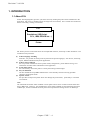
This technical reference manual is intended to help you get the most out of each of the emulation
modes supported by your HL Series laserprinter. It is divided into nine sections - this introductory
section and one section for each of the emulation modes. Each emulation mode section describes the
software commands (the escape sequences and control codes) that you can use to make the printer
perform each of its available functions. Some example programs are included to give you useful
ideas.
This manual is for our PCL5 models. For the differences between each model, see the Appendix
"Model Comparison."
For basic set-up information, such as how to connect the printer to your computer, look in the User
guide. The User guide also describes the printers control panel and how you can set various options
using the keys.
Areas of use
There are several different applications for which you may want to use your HL Series laserprinter.
Four general areas are outlined in the following sections.
USING WORD-PROCESSING PACKAGES AND SPREADSHEETS
You may simply wish to use the printer with your software application packages, such
as word-processors or spreadsheets. Many software packages automatically send
commands to the printer requesting particular type styles, character sizes and
specifying page set-up information and other relevant data. In this case you will not
need to use this manual, as your software package will perform the task of controlling
the printer for you. Other packages allow you to embed software commands within
your word-processed or spreadsheet documents. This manual describes the commands
you need, and you can simply include them in the form that your package requires. In
either case, read the documentation that came with your software to find out its own
specific requirements for driving a printer.
2
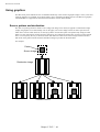
GRAPHICS
HP-GL/2 or HP-GL mode offers many powerful graphic features that enable you to draw and print
detailed images quickly and easily. Many commercial graphic packages, notably computer-aided
design applications programs, produce HP-GL/2 or HP-GL output. LaserJet mode also has several
graphics features. You can either write your own programs to generate images or use existing
graphics software.
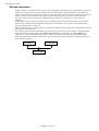
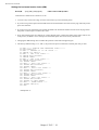
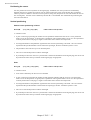
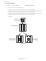
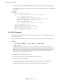
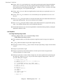
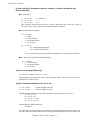
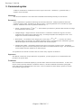
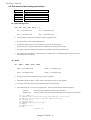
PROGRAMMING
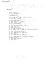
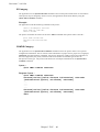
If you are writing software, for example in BASIC or C, to drive the printer, the description and
formal specification of each command will enable you to transcribe them straight into your
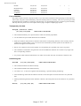
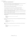
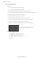
programs. Below is a simple example of a program to draw and print a three inch black square. The
program is given in both C and BASIC.
C language program
#include <stdio.h>
main()
{
FILE *prn; /* initialization section */
prn = fopen("PRN","wb");
fprintf(prn,"\33E"); /* Esc E - Reset the printer */
fprintf(prn,"\33%0B"); /* Esc%0B - Enter HP-GL/2 */
fprintf(prn,"IN"); /* Initialize */
fprintf(prn,"SP1PA1024,1024"); /* Select pen 1 & move to 0,0
*/
fprintf(prn,"PDFT1RA4096,4096"); /* Draw 3" solid square */
fprintf(prn,"\33%0A"); /* Quit HP-GL/2 & restore original
cursor position */
fprintf(prn,"\33E /* Reset and eject page */
}
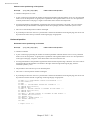
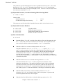
BASIC language program
10 LPRINT CHR$(27);"E"; :REM Esc E - Reset the printer
20 LPRINT CHR$(27);"%0B"; :REM Esc%0B - Enter HP-GL/2
30 LPRINT "IN"; :REM Initialize
40 LPRINT "SP1PA1024,1024"; :REM Select pen 1 & move to 0,0
50 LPRINT "PDFT1RA4096,4096"; :REM Draw 3" solid square
60 LPRINT CHR$(27);"%0A"; :REM Quit HP-GL/2 & restore
original cursor position
70 LPRINT CHR$(27);"E"; :REM Reset and eject page
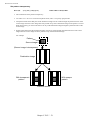
FONT DEVELOPMENT
In LaserJet 4 mode you can send your own character designs to the HL Series laserprinter and print
text using them. To do this you need first to design your characters on paper. Having done this you
can then either input and download your characters using a commercial software package, or encode
your designs numerically and write your own program to download them.
3
Revision C 16/01/96
Chapter 2
PCL
Chapter 2 "PCL" - 1
Revision C 16/01/96
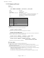
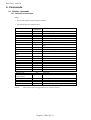
Command list
Control Codes
Escape sequences
Esc&k#G
Esc&s#C
EscY
EscZ
6
Line Termination
End-of-line wrap
Display function mode
Display function mode
Environments
7
8
8
8
8
9
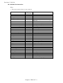
Job Control
Esc&l#A
Esc&l#H
Esc&l#U
Esc&l#Z
Esc&l#S
Esc&a#G
Esc&l#X
Esc&l1T
EscE
EscCR FD
EscCR!#R
Escz
Esc%-12345X
EscCR##
Page size
Paper source
Left long-edge offset registration
Top offset registration
Simplex/Duplex printing
Paper Side Selection
Number of copies
Job separation command
Reset
Reset to factory default settings
Reset to user settings
Printer self test
Exit current emulation mode
Change emulation mode
10
10
11
11
12
12
12
12
13
13
13
13
14
14
14
The Page
Esc&u#D
Esc&a#L
Esc&a#M
Esc9
Esc&l#E
Esc&l#C
Esc&k#H
Esc&l#D
Esc&l#F
Esc&l#P
Esc&l#L
Esc&a#R
Esc*p#Y
Esc&a#V
Esc&a#C
Esc*p#X
Esc&a#H
Esc&f#S
Esc=
Esc&l#O
Esc&a#P
Unit of measure
Setting the left and right margins
Setting the left and right margin
Resetting the horizontal margins
Setting the top margin
Setting the vertical motion index (VMI)
Setting the horizontal motion index (HMI)
Setting line spacing
Text length
Page length
Perforation skip
Vertical positioning -rows
Vertical positioning - units
Vertical positioning - decipoints
Horizontal position - columns
Horizontal position - units
Horizontal position - decipoints
Using the cursor position stack
Half line feed
Logical page orientation
Text direction
15
18
19
19
20
20
21
21
23
23
24
24
25
25
26
26
27
28
29
29
30
31
Using fonts
Esc(3@, Esc)3@
SI, SO
Esc*c#R
Esc(f#W
Esc*c#S
Esc(symbol set ID
Esc(s#C, Esc)s#C
Esc(s#P, Esc)s#P
Esc(s#H, Esc)s#H
Selecting the default fonts
Switching between the primary and secondary font
Symbol Set ID Code Command
Define symbol set
Symbol Set Control Command
Select the symbol set
Select the symbol set
Selecting the type of character spacing
Selecting the pitch
32
34
34
36
37
39
39
40
41
42
Chapter 2 "PCL" - 2
Revision C 16/01/96
Esc(s#V, Esc)s#V
EscCR!#H, EscCR!#V
Esc(s#S, Esc)s#S
Esc(s#B, Esc)s#B
Esc(s#T, Esc)s#T
Esc&p#X
Esc&d#D, Esc&d@
Esc&*c#D
Esc*c#F
Esc(#X, Esc)#X
Esc)s#W
Esc*c#E
Esc(s#W
Seelcting the height
Scaling the scalable fonts vertically or horizontally
Selecting the style
Selecting the stroke weight
Selecting the typeface
Transparent print data
Underlining text
Font ID
Operations on downloaded fonts
Selecting a downloaded font
Sending the font descriptor
Sending a character code
Sending a character descriptor and data
42
43
43
44
44
45
45
46
46
47
47
61
61
Using graphics
Esc*v#N
Esc*v#O
Esc*c#G
Esc*c#W
Esc*p#R
Esc*c#Q
Esc*v#T
Esc*c#A, Esc*c#H
Esc*c#B, Esc*c#V
Esc*c#P
Esc*t#R
EscCR ##
Esc*r#F
Esc*r#T
Esc*r#S
Esc*b#Y
Esc*b#M
Esc*r#A
Esc*b#W
Esc*b#C
Esc*rB
Esc*rC
Esc%#B
Esc*c0T
Esc*c#Y
Esc*c#X
Esc*c#L
Esc*c#K
Set source transparency
Set pattern transparency
Set area fill identity
User-defined pattern command
Set pattern reference point
User-defined pattern control
Set pattern type
Set rectangle width
Set rectangle height
Draw filled rectangle
Set raster resolution
Set high resolution control
Set raster image orientation
Set raster area height
Set raster area width
set raster y-offset
Set compression mode
Start raster transfer
Send raster data
Compress transfer graphics
End raster transfer
End raster transfer
Enter HP-GL/2 mode
Set picture frame anchor point
Set picture frame vertical size
Set picture frame horizontal size
Specify vertical plot size
Specify horizontal plot size
68
69
70
71
71
72
72
73
74
75
76
77
77
77
78
78
79
79
84
85
85
85
85
87
87
87
87
88
88
Macros
Esc&f#Y
Esc&f0X
Esc&f1X
Esc&f2X
Esc&f3X
Esc&f4X
Esc&f5X
Esc&f6X
Esc&f7X
Esc&f8X
Esc&f9X
Esc&f1030X
Esc&f1036X
Esc&f1038X
Macro ID
Start macro definition
End macro definition
Execute macro
Call macro
Enable macro for overlay
Disable macro for overlay
Delete all macros
Delete all temporary macros
Delete macro
Make macro temporary
Delete all macros from PCMCIA memory card
Delete macro from PCMCIA memory card
Save macro into PCMCIA memory card
89
89
89
90
90
90
90
90
91
91
91
91
91
91
91
Chapter 2 "PCL" - 3
Revision C 16/01/96
EscCR!#E
Esc&b#W
EscCR!1234#M
Execute Data
AppleTalk Configuration
MIO Video I/O port control
93
94
94
Status Readback
Esc*s#T
Esc*s#U
Esc*s#I
Esc*s1M
Esc&r#F
Esc*s#X
Set status readback location type
Set status readback location unit
Inquire status readback entity
Free space command
Flush All pages command
Echo command
95
97
97
98
104
105
105
Chapter 2 "PCL" - 4
Revision C 16/01/96
Introduction
This laserprinter provides a complete emulation of the Hewlett Packard LaserJet 4 printer. Features include raster
and vector graphics, support for bitmap and scalable fonts and page control. There are many resident fonts in the
printer and you can gain access to more by inserting a font cartridge/card or PCMCIA card into the printer or by
downloading fonts from your computer.
Chapter 2 "PCL" - 5
Revision C 16/01/96
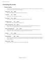
Controlling the printer
Control codes
Control codes are ASCII codes that tell the printer to perform a given function, such as a carriage return. You can
send these codes to the printer as part of a program.
Backspace
(08)
<08h>
ASCII code 8. This code moves the cursor one column to the left.
Line feed
(10)
<0Ah>
ASCII code 10. This code performs a line feed.
Form feed
(12)
<0Ch>
ASCII code 12. This code ejects the most recently printed page from the printer.
Carriage return
(13)
<0Dh>
ASCII code 13. This code performs a carriage return.
Select primary font (14)
<0Eh>
ASCII code 15. When you send this code to the printer subsequent characters will be printed in the current
primary font. This is explained further in the sub-section entitled “Using fonts”.
Select secondary font
(15)
<0Fh>
ASCII code 14. When you send this code to the printer subsequent characters will be printed in the current
secondary font. This is explained further in the sub-section entitled “Using fonts”.
Escape
(27)
<1Bh>
ASCII code 27. You must use this character code to start every instruction sequence that you send to the printer.
Horizontal tab
(09)
<09h>
ASCII code 9. This code moves the cursor one tab position to the right. The tab positions are at the left margin and
at the left edge of every 8th column as defined by the horizontal motion index (HMI) described in the next section,
entitled “The Page”.
Space (32)
<20h>
ASCII code 32. This code moves the cursor one column to the right.
Chapter 2 "PCL" - 6
Revision C 16/01/96
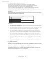
Escape sequences
Escape sequences, also known as PCL (Printer Control Language) commands, tell the printer which operations to
perform. An escape sequence consists of the Esc character followed by a string of characters which define the
operation to be performed. Some escape sequences require parameter values. These are included in the sequence as
numeric characters. The final letter of an escape sequence must be uppercase: all others must be lowercase.
You can send the printer instructions by embedding escape sequences in programs or in word processed
documents.
In this manual escape sequences are shown as they would be entered, except that the character # in a sequence
indicates that a number should be included at that point in the sequence. If no number is included the printer
interprets that parameter’s value as 0.
When downloading fonts or sending raster scan images to the printer the final uppercase character of the sequence
is followed by the relevant data.
Two escape sequences can be combined into one if the first three characters of each sequence (including the Esc
character itself) are the same. Hence, Esc*c45G and Esc*c2P may be combined to give Esc*c45g2P. The
uppercase ‘G’ which terminated the first sequence becomes a lowercase character in the combined sequence.
combined escape sequences are executed left to right, so be careful to place commands in the order in which you
want them to be executed.
Esc*c45G
Esc*c2P
Esc*c45g2P
Chapter 2 "PCL" - 7
Revision C 16/01/96
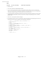
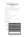
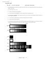
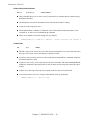
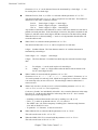
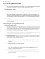
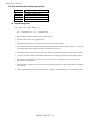
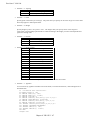
Line termination
You can set the carriage return, line feed and form feed control codes to perform compound functions. You can
either do this using the printer’s control panel (see the User Guide) or by sending the printer the following escape
sequence:
• 0 = Carriage return, line feed and form feed perform their normal functions.
• 1 = Carriage return performs carriage return/line feed, line feed and form feed perform their normal functions.
• 2 = Carriage return performs its normal function, line feed performs carriage return/line feed, and form feed
performs carriage return/form feed.
• 3 = Carriage return performs carriage return/line feed, line feed performs carriage return/line feed, and form
feed performs carriage return/form feed.
0
1
2
3
CR→CR
CR→CR+LF
CR→CR
CR→CR+LF
LF→LF
LF→LF
LF→CR+LF
LF→CR+LF
FF→FF
FF→FF
FF→CR+FF
FF→CR+FF
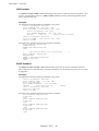
End-of-line wrap
If the printer tries to print a line of text that is longer than the width of the text area, the end of the line will
normally be lost. However, you can set the printer to flow text onto the next line so that text is not lost.
You can turn on the automatic text wrap feature either from the printer’s control panel (see the User Guide) or by
sending the printer the following escape sequence:
Esc&s0C
(27)(38)(115)(48)(67)
<1Bh><26h><73h><30h><43h>
To turn off the facility send:
Esc&s1C
(27)(38)(115)(49)(67)
<1Bh><26h><73h><31h><43h>
Display functions mode
You can choose to make the printer print escape sequences instead of executing them. Send the printer the
following sequence:
EscY
(27)(89)
<1B><59>
Now the printer prints out escape sequences and prints the characters of the control codes. It does not execute
them. The only exceptions to this are CR, the carriage return code, which causes a carriage return and line feed to
be performed, and the EscZ escape sequence which turns the mode off.
To turn the display functions mode off and enable escape sequences to be executed again send:
EscZ
(27)(90)
<1B><5A>
The printer exits the display function mode after printing a character of code 1B Hex and the letter "Z". All
subsequent escape sequences and control codes are executed normally and not printed literally.
Chapter 2 "PCL" - 8
Revision C 16/01/96
Environments
Factory default environment
The factory default environment is the collection of printer settings programmed into the printer before it leaves
the factory. You can restore the factory default environment using the printer’s control panel.
See the User's Guide to find how to reset the printer from the printer's control panel.
Some settings cannot be restored to the factory default environment with the RESET operation from printer's
control panel.
User default environment
The user default environment is a combination of factory default settings and settings which the user has made
from the printer’s control panel or remote printer console. You can store user default setting(s) in the printer by
using the printer control panel. You can restore the user default environment either by sending the reset escape
sequence to the printer, EscE, or by performing a reset from the printer’s control panel.
Modified print environment
The modified print environment is made up of all the current printer settings. If you call a macro or go into HPGL/2 graphics language the modified print environment settings are saved. When the macro has been executed, or
when you quit HP-GL/2, these saved settings are restored. The modified print environment consists of settings for
the following features:
Page length
Page size
Orientation
Left registration
Top registration
Paper source
Number of copies
Margins
Perforation skip mode
Line termination mode
End-of line wrap
Current font
Primary font characteristics
Secondary font characteristicsHMI
Primary font
Secondary font
Font ID
Character codeMacro ID
VMI/Line spacing
Horizontal rectangle size
Vertical rectangle size
Area fill ID
Raster graphics resolution
Raster graphics presentation mode
Raster graphics left margin
Pattern ID
Current pattern
Source transparency mode
Pattern transparency mode
Print direction
Raster graphics compression mode
Underline mode
Raster graphics height
Raster graphics width
Macro overlay environment
The macro overlay environment is a combination of the user default environment and the current modified print
environment. The overlay environments settings take effect when a macro is enabled for automatic overlay. This is
detailed in the section of this manual in which macros are described.
Chapter 2 "PCL" - 9
Revision C 16/01/96
Job control
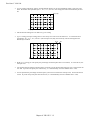
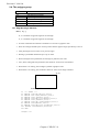
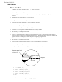
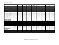
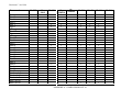
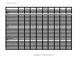
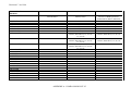
Page size
Esc&l#A
(27)(38)(108)#(65)
<1Bh><26h><6Ch>#<41h>
# stands for the type of paper or envelope to be used.
• Values for # correspond to the paper or envelope sizes shown in the table. Envelopes sizes are shown in the
shaded part of the table.
1
2
3
26
100
1024
1025
1026
2048
80
81
90
91
Executive
Letter
Legal
A4
B5
B6 (HL1260 only)
A5 (HL1260 only)
A6 (HL1260 only)
16" (HL660 only)
Monarch
COM-10
International DL
International C5
• When the printer receives this command any unprinted pages are printed, and the left, right and top margins,
and the text length are set to their user defaults for the new page size.
• The cursor is moved to the top left of the text area on the new page.
• Depending on your model, you may also set the page size from the printer’s control panel or remote printer
console program by setting PAPER in PAGE FORMAT mode to the page size you require (see the User
Guide).
• If the paper size you select differs from the size of the currently loaded paper, a message appears in the control
panel or display window prompting you to load the selected size of paper (except for HL-660 series printer).
Example)
Select letter size
Esc&l2A
<1Bh><26h><6Ch><32h><41h>
Chapter 2 "PCL" - 10
Revision C 16/01/96
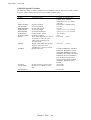
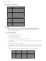
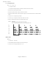
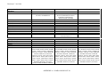
Paper source
Esc&l#H
(27)(38)(108)#(72)
<1Bh><26h><6Ch>#<48h>
# denotes the paper source.
Values for # may be 0, 1, 2, 3, or 4.
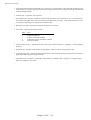
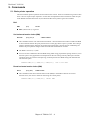
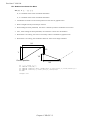
•
•
•
•
•
•
•
•
•
If # = 0 the current page is ejected and the paper source remains the same.
If # = 1 the current page is printed and the upper cassette becomes the paper source.
If # = 2 the current page is printed and paper is fed in manually.
If # = 3 the current page is printed and envelopes are fed in manually.
If # = 4 the current page is printed and the lower cassette becomes the paper source.
If # = 4 the current page is printed and the multi-purpose tray becomes the paper source. (HL-1260)
If # = 5 the current page is printed and the lower cassette becomes the paper source. (HL-1260)
If # = 1 or # = 2 either paper or envelopes may be fed in, depending on the current page size setting.
The cursor is positioned at the top left of the text area on the next page.
#=0
#=1
#=2
#=3
#=4
#=5
HL-10h
Eject
Tray 1
Manual Feed
Envelope
Tray 2
HL-660
←
Sheet Feeder
←
N/A
N/A
N/A
HL-1260
←
Tray 1
←
Envelope
MP Tray
Tray 2
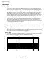
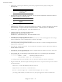
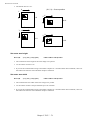
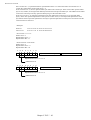
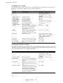
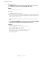
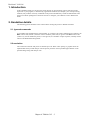
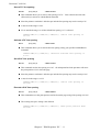
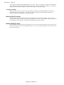
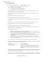
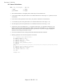
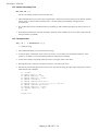
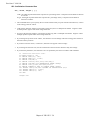
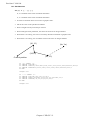
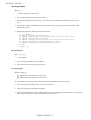
Left long-edge offset registration
Esc&l#U
(27)(38)(108)#(85)
<1Bh><26h><6Ch>#<55h>
# stands for the distance in decipoints (1/720") that the left edge of the logical page is to be moved.
• Values for # may be in the range -32,767 to 32,767.
• The distance specified is relative to the logical page’s current position.
• # can be positive or negative. Use a positive number to move the logical page to the right on the physical page,
and a negative number to move it to the left.
AAAA
AAAA
AAAA
AAAA
AAAA
AAAA
AAAA
AAAA
AAAA
AAAA
AAAA
AAAA
AAAA
AAAA
AAAA
AAAA
AAAA
AAAA
AAAA
AAAA
AAAA
AAAA
AAAA
AAAA
AAAA
AAAA
AAAA
AAAA
AAAA
AAAA
AAAA
AAAA
AAAA
AAAA
AAAAAAAA
AAAA
AAAA
AAAA
AAAA
AAAA
AAAA
AAAA
AAAA
AAAA
AAAA
AAAA
AAAA
AAAA
AAAA
Positive
AAAA
AAAA
AAAA
AAAA
AAAA
AAAA
AAAA
AAAA
AAAA
AAAA
AAAA
AAAA
AAAA
AAAA
AAAA
AAAA
AAAA
AAAA
AAAA
AAAA
AAAA
AAAA
AAAA
AAAA
AAAA
AAAA
AAAA
AAAA
AAAA
AAAA
AAAA
AAAA
AAAA
AAAA
AAAA
AAAA
AAAA
AAAA
AAAA
AAAA
AAAA
AAAA
AAAA
AAAA
AAAA
AAAA
AAAA
AAAA
AAAA
AAAA
AAAA
AAAA
AAAA
AAAA
AAAA
AAAA
AAAA
AAAA
AAAA
AAAA
AAAA
AAAA
AAAA
AAAA
AAAA
AAAA
AAAA
AAAA
AAAA
AAAA
AAAA
AAAA
AAAA
AAAA
AAAA
AAAA
AAAA
AAAA
AAAA
AAAA
AAAA
AAAA
AAAA
AAAA
AAAA
AAAA
AAAA
AAAA
AAAA
AAAA
AAAA
AAAA
AAAA
AAAA
AAAA
AAAA
AAAA
AAAA
AAAA
AAAA
AAAA
AAAA
AAAA
AAAA
AAAA
AAAA
AAAA
AAAA
AAAA
AAAAAAAA
AAAA
AAAA
AAAA
AAAA
AAAA
AAAA
AAAAAAAA
AAAAAAAA
AAAA
AAAA
AAAA
AAAA
AAAA
AAAA
AAAA
AAAA
AAAA
AAAA
AAAA
AAAA
AAAA
AAAA
AAAA
AAAA
AAAA
AAAA
AAAA
AAAA
AAAA
AAAA
AAAA
AAAA
AAAA
AAAA
AAAA
AAAA
AAAA
AAAA
AAAA
AAAA
AAAA
AAAA
AAAA
AAAA
AAAA
AAAA
AAAA
AAAA
AAAA
AAAA
AAAA
AAAA
AAAA
AAAA
AAAA
AAAA
Negative
AAAAAAAA
AAAA
AAAA
AAAA
AAAA
AAAA
AAAAAAAAAAAA
AAAA
Chapter 2 "PCL" - 11
Revision C 16/01/96
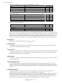
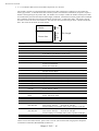
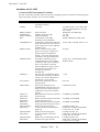
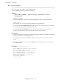
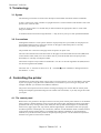
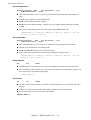
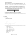
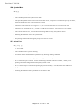
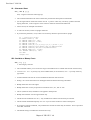
Top offset registration
Esc&ll#Z
(27)(38)(108)#(90)
<1Bh><26h><6Ch>#<5Ah>
# stands for the distance in decipoints (1/720") that the top edge of the logical page is to be moved.
• Values for # may be in the range -32,767 to 32,767.
• The distance specified is relative to the logical page’s current position.
• # can be positive or negative. Use a positive number to move the logical page downwards on the physical page,
and a negative number to move it upwards.
AAAANegative
AAAAAAAAAAAA
AAAA
AAAA
AAAAAAAA
AAAAAAAA
AAAAAAAA
AAAAAAAA
AAAA
AAAAAAAAAAAAAAAA
AAAA
AAAAAAAAAAAA
AAAAAAAA
AAAAAAAA
AAAAAAAA
AAAA
Positive
AAAA
AAAA
AAAA
AAAA
AAAA
AAAAAAAAAAAAAAAAAAAA
AAAAAAAAAAAAAAAAAAAA
AAAAAAAAAAAAAAAAAAAA
AAAA
AAAAAAAAAAAAAAAA
AAAA
AAAA
AAAAAAAA
AAAAAAAA
AAAAAAAA
AAAAAAAA
AAAA
AAAAAAAAAAAA
AAAAAAAA
AAAA
AAAA
AAAA
AAAA
AAAAAAAAAAAAAAAAAAAA
AAAA
AAAAAAAAAAAA
AAAAAAAA
AAAA
AAAA
AAAA
AAAA
AAAAAAAAAAAAAAAAAAAA
AAAAAAAAAAAAAAAAAAAA
AAAA
AAAA
AAAA
AAAA
AAAAAAAAAAAAAAAAAAAA
AAAA
AAAAAAAAAAAAAAAAAAAA
AAAA
AAAAAAAAAAAA
AAAAAAAA
AAAAAAAAAAAAAAAA
AAAA
AAAAAAAAAAAAAAAA
AAAA
AAAA
AAAA
AAAAAAAA
AAAAAAAA
AAAAAAAA
AAAAAAAA
AAAAAAAA
AAAAAAAA
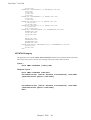
AAAAAAAA
AAAAAAAA
AAAA
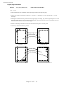
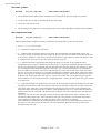
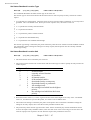
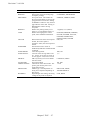
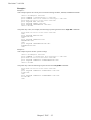
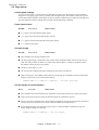
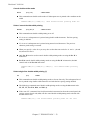
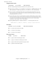
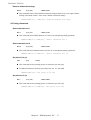
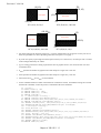
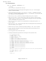
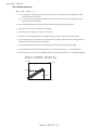
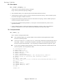
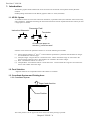
Simplex/Duplex printing ( Only for HL-1260 )
Esc&l#S
(27)(38)(108)#(83)
<1Bh><26h><6Ch>#<53h>
# can be 0, 1, or 2.
• # = 0 indicates the Simplex printing.
• # = 1 indicates the Duplex - Long edge binding printing.
• # = 2 indicates the Duplex - Short edge binding printing.
• If the optional duplex unit is not installed to the printer, this mode is fixed at Simplex mode.
• This command setting is not saved in the printer's NV-RAM.
[Long Edge Binding]
[Short Edge Binding]
Paper Side Selection
Esc&a#G (27)(38)(97)#(71) <1Bh><26h><61h>#<47h>
# can be 0, 1, or 2.
• # = 0 indicates the next side. If there are the page which is in process, the printer finishes the process to the
page. If there are no page in process, this command is ignored.
Chapter 2 "PCL" - 12
Revision C 16/01/96
• # = 1 indicates the front side.
If the currently processing page is odd page, the printer finishes the process to the page and attaches a dammy
page.
If the odd page had already processed to the page and even page has not been processed yet, only a dammy
page is attached.
If the currently processing page is even page, the printer finishes the process to the page.
If even and odd pages had been processed and the next odd page has not been processed yet, this command is
ignored.
• # = 2 indicates the back side.
If the currently processing page is odd page, the printer finishes the process to the page.
If the odd page had already processed to the page and even page has not been processed yet, this command is
ignored.
If the currently processing page is even page, the printer finishes the process to the page and attaches a dummy
(white) page.
If even and odd pages had been processed and the next odd page has not been processed yet, only a dummy
(white) page is attached.
Job separation command
Esc&ll1T
(27)(38)(108)(49)(84)
<1Bh><26h><6Ch><31h><54h>
• It is recommended to insert this command at the end of each job.
Reset
EscE
(27)(69)
<1Bh><45h>
• A printer reset restores the user default environment, deletes any temporary fonts and temporary macros.
• Any pages that have been transmitted are printed out.
• You can also perform a printer reset using the printer’s control panel or remote printer console program (see
the User Guide).
Reset to factory default settings
EscCRFD
(27)(13)(70)(68)
<1Bh><0Dh><46h><44h>
• This command causes a factory reset to be performed, restoring all the printer’s factory default settings. See the
section “Factory default environment” for a list of the factory default settings.
• You can also perform a factory reset using the printer’s control panel or remote printer console program (see
the User Guide).
Reset to user settings
EscCR!#R
(27)(13)(33)#(82) <1Bh><0Dh><21h>#<52h>
• # can be 0, 1 or 2.
• #0 indicates the current settings are restored. Unlike Esc E reset command, Esc CR!0R command reset input
buffer.
• #1 indicates the user settings 1 are restored, if the printer supports multi user settings.
• #2 indicates the user settings 2 are restored, if the printer supports multi user settings.
Chapter 2 "PCL" - 13
Revision C 16/01/96
• Depending on models you may make the control panel setting locked ("SETTING LOCK=ON"). In that case,
the parameters 1 and 2 are ignored.
Printer self test
Escz
(27)(122)
<1Bh><7Ah>
• A printer self test causes a test sheet to be printed out to show that the machine is working properly. Depending
on the models, you may also see the test pattern for HRC setting.
Exit current emulation mode
Esc%-12345X
(27)(37)(45)(49)(50)(51)(52)(53)(88)
<1Bh><25h><2Dh><31h><32h><33h><34h><35h><58h>
• When the printer receives this command, all page data already received is printed out.
• All settings are reset to user settings.
• Exit the current emulation mode.
Change emulation mode
EscCRGL
(27)(13)(71)(76) <1Bh><0Dh><47h><4Ch>
• This command changes the emulation mode to HP-GL mode.
EscCRAB
(27)(13)(65)(66) <1Bh><0Dh><41h><42h>
• This command changes the emulation mode to BR-Script Batch mode.
EscCRAI
(27)(13)(65)(73) <1Bh><0Dh><41h><49h>
• This command changes the emulation mode to BR-Script Interactive mode.
EscCRP or EscCRD
(27)(13)(80)
<1Bh><0Dh><50h>
(27)(13)(68)
<1Bh><0Dh><44h>
• These two commands change the emulation mode to Diablo 630 mode.
EscCRI
(27)(13)(73)
<1Bh><0Dh><49h>
• This command changes the emulation mode to IBM Proprinter XL mode.
EscCRE
(27)(13)(69)
<1Bh><0Dh><45h>
• This command changes the emulation mode to Epson FX-850 mode.
EscCRTD
(27)(13)(84)(68) <1Bh><0Dh><54h><44h>
• This command changes the emulation mode to Brother Twinriter DP emulation mode.
EscCRTW
(27)(13)(84)(87) <1Bh><0Dh><54h><57h>
• This command changes the emulation mode to Brother Twinriter WP emulation mode.
• Depending on the models, you can also switch between emulation modes using the printer’s control panel (see
the User Guide).
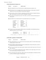
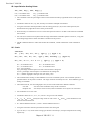
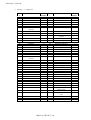
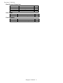
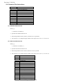
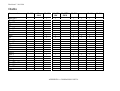
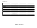
Emulations availabe for each model are listed below.
PCL HP-GL BR-Script BR-Script 2 Diablo 630
HL-4Ve
HL-10V/DV
HL-10PS/DPS
HL-6V
HL-10h
HL-660
HL-1260
¡
¡
¡
¡
¡
¡
¡
¡
¡
¡
¡
¡
¡
¡
¡
Chapter 2 "PCL" - 14
Epson
FX-850
IBM
Proprinter XL
¡
¡
¡
¡
¡
¡
¡
¡
¡
¡
Twinriter
¡
¡
Revision C 16/01/96
The page
Physical page
The physical page refers to the size of the paper or envelope currently in use: A4, Letter, B5, JIS B5, Legal and
Executive are the permitted paper sizes: Monarch, COM-10, International DL and International C5 are the
allowable envelope sizes.
Printable area
The printable area is a rectangular area of the physical page on which the printer can print. Its edges are 1/6" in
from the edges of the physical page.
Logical page
The logical page is the area of the physical page where the cursor can be positioned. (Although the printer does
not really have a cursor, we refer to the position on the page from which the printing of a character or graphic
starts as the cursor position). You can alter the size of the logical page using the left offset registration and top
offset registration commands. The logical page is also called the PCL (printer control language) addressable area.
Text area
The text area is the area of the physical page on which text can be printed, and is determined by the left, right and
top margin settings, the text length and whether the perforation skip facility is on or off. All these settings can be
made either from the printer’s control panel (see the User Guide) or using PCL commands.
HP-GL/2 graphics window
The HP-GL/2 graphics window is the area of the physical page on which images can be printed using HP-GL/2
commands. This is described in the HP-GL/2 section of this manual. The default graphics window is bound by the
left and right edges of the logical page and horizontal boundaries half an inch below the top and above the bottom
of the logical page.
Chapter 2 "PCL" - 15
Revision C 16/01/96
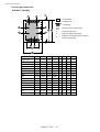
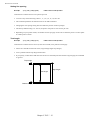
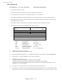
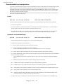
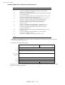
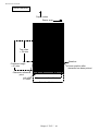
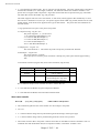
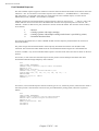
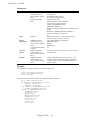
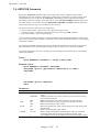
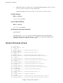
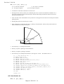
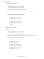
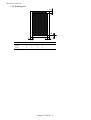
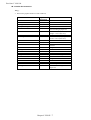
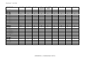
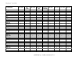
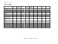
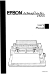
Portrait page dimensions
(DEFAULT VALUES)
H
G
F
Physical page
Printable area
Logical page
E
E
G
G
Default HP-GL/2 picture frame
D
B
B
Physical page length
D
Maximum logical page length
F
DIstance from edge of physical page to
edge of logical page
F
G
H
C
A
PAPER SIZE
A
B
C
LETTER
2550 3300 2400
LEGAL
2550 4200 2400
EXECUTIVE 2175 3150 2025
A4
2480 3507 2338
B5
2078 2952 1936
JIS B5
2148 3030 2010
B6
1476 2078 1334
A5
1754 2480 1612
A6
1240 1754 1098
A4 80 chara
2480 3507 2400
A4 long
2480 4783 2400
COM-10
1237 2850 1087
MONARCH
1162 2250 1012
C5
1913 2704 1771
DL
1299 2598 1157
All measurements in 1/300'"
D
3300
4200
3150
3507
2952
3030
2078
2480
1754
3507
4783
2850
2250
2704
2598
Chapter 2 "PCL" - 16
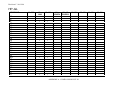
E
75
75
75
71
71
69
71
71
71
40
40
75
75
71
71
F
0
0
0
0
0
0
0
0
0
0
0
0
0
0
0
G
50
50
50
50
50
50
50
50
50
40
40
50
50
50
50
H
150
150
150
150
150
150
150
150
150
150
150
150
150
150
150
Revision C 16/01/96
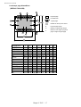
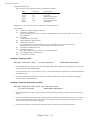
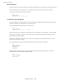
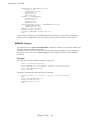
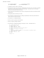
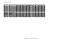
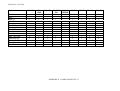
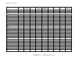
Landscape page dimenSions
( DEFAULT VALUES)
H
G
F
Physical page
Printable area
E
E
Logical page
D
B
Default HP-GL/2 picture frame
G
G
B
Physical page length
D
Maximum logical page length
F
DIstance from edge of physical
page to edge of logical page
G
H
F
C
A
PAPER SIZE
A
B
C
D
LETTER
3300 2550 3180 2550
LEGAL
4200 2550 4080 2550
EXECUTIVE
3150 2175 3030 2175
A4
3507 2480 3389 2480
B5
2952 2078 2834 2078
JIS B5
3030 2148 2910 2148
B6
2078 1476 1960 1476
A5
2480 1754 2362 1754
A6
1754 1240 1636 1240
A4 long
4783 2480 4665 2480
COM-10
2850 1237 2730 1237
MONARCH
2250 1162 2130 1162
C5
2704 1913 2586 1913
DL
2598 1299 2480 1299
All measurements in 1/300'"
E
60
60
60
59
59
60
59
59
59
59
60
60
59
59
F
0
0
0
0
0
0
0
0
0
0
0
0
0
0
Chapter 2 "PCL" - 17
G
50
50
50
50
50
50
50
50
50
50
50
50
50
50
H
150
150
150
150
150
150
150
150
150
150
150
150
150
150
Revision C 16/01/96
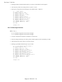
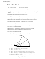
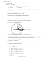
Coordinates
The printer control language coordinate system has its origin at the intersection of the left edge of the logical page
and the top margin. The x-coordinate value of the current cursor position increases as the cursor moves from left
to right, the y-coordinate value increases as the cursor moves down the page. The cursor can be explicitly
positioned anywhere on the current logical page using the PCL coordinate system. In addition, the cursor’s
coordinate position will change as text and graphics are printed.
Units
You can specify cursor movement within the PCL coordinate system using one of three different unit systems.
Decipoints
A decipoint is one-tenth of a typographic point measurement = 1/720".
Rows and columns
Using the horizontal motion index (HMI) (Esc&k#H) and vertical motion index (VMI)(Esc&l#C) commands you
can set the width of a column and the height of a row. You can then use the column width and row height as the
units of the coordinate system. The line-spacing command is an alternative to the VMI command.
Units
A unit is the measurement which can be defined by the unit of measure command.
Unit of Measure
Esc&u#D
(27)(38)(117)#(68)
<1Bh><26h><75h>#<44h>
• # value can be 96, 100, 120, 144, 150, 160, 180, 200, 225, 240, 288, 300, 360, 400, 450, 480, 600, 720, 800,
900, 1200, 1440, 1800, 2400, 3600, 7200.
• # stands for the unit of measurement in dots per inch.
• The value set by this command is used as the unit setting for use by other setting commands such as ESC*p#X.
• The default value of # is 300.
Example)
Esc&u300D
Esc&u600D
Esc*p+100x+200Y
move cursor 100/300 inch right and 200/300 inch down.
Esc*p+100x+200Y
move cursor 100/600 inch right and 200/600 inch down.
Chapter 2 "PCL" - 18
Revision C 16/01/96
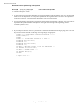
Setting the left and right margins
Esc&a#L
(27)(38)(97)#(76)
<1Bh><26h><61h>#<4Ch>
# stands for the distance between the left edge of the logical page and the left margin in columns.
Esc&a#M
(27)(38)(97)#(77)
<1Bh><26h><61h>#<4Dh>
# stands for the distance between the left edge of the logical page and the right margin in columns.
• The column width is as defined by the HMI. If you subsequently change the HMI the margin positions that you
have set do not change - that is, when you specify margin positions they remain fixed physically until you
specify new ones or reset them to default values.
• You cannot specify a value for the left margin that is greater than the value of the current right margin.
• If the current cursor position is to the left of your new left margin setting, the cursor will be moved to the new
left margin.
• You cannot set the right margin to be further right than the right edge of the logical page.
• If the current cursor position is to the right of your new right margin setting, the cursor will be moved to the
new right margin.
• The factory default left and right margin settings are at the left and right edges of the logical page respectively.
• Depending on your model, margin settings can be made from the printer’s control panel (see the User Guide).
10 REM ***** SET AND CLEAR SIDE MARGINS *****
20 ESC$=CHR$(27)
30 WIDTH "LPT1:",255
40 REM --- END OF LINE WRAP ON --50 LPRINT ESC$+"&s0C";
60 REM --- LEFT MARGIN SET TO 10 COLUMNS ---70 LPRINT ESC$+"&a10L";
80 REM --- RIGHT MARGIN SET TO 70 COLUMNS ---90 LPRINT ESC$+"&a70M";
100 REM --- PRINT "0123456789" 10 TIMES
110 FOR I=1 TO 10
120 LPRINT "0123456789";
130 NEXT
140 LPRINT
150 REM --- CLEAR SIDE MARGIN ---160 LPRINT ESC$+"9";
170 REM --- PRINT "0123456789" 10 TIMES
180 FOR I=1 TO 10
190 LPRINT "0123456789";
200 NEXT
210 REM --- PAPER EJECT ---220 LPRINT CHR$(12);
230 END
Chapter 2 "PCL" - 19
Revision C 16/01/96
Resetting the horizontal margins
Esc9
(27)(39)
<1Bh><39h>
• This command resets the left and right margins to the left and right edges of the logical page respectively.
Setting the top margin
Esc&ll#E
(27)(38)(108)#(69)
<1Bh><26h><6Ch>#<45h>
# stands for the distance between the top of the logical page and the top margin in rows.
• The row height is as defined by the VMI. If you subsequently change the VMI (or the line spacing) the top
margin position that you have set does not change - that is, when you specify the top margin position it remains
fixed physically until you specify a new one or reset it to a default value.
• The top margin command is ignored if you try to set a margin greater than the current length of the logical
page.
• The top margin command is ignored if the current VMI is 0.
• The factory default top margin setting is half an inch below the top of the logical page.
• Depending on your model, the top margin can be set from the printer’s control panel (see the User Guide).
10
20
30
40
50
60
70
REM ******* SET TOP MARGIN TO 10 LINES *******
REM
ESC$=CHR$(27)
LPRINT ESC$+"&l10E";
LPRINT "10 LINES "
LPRINT CHR$(12);
END
Chapter 2 "PCL" - 20
Revision C 16/01/96
Setting the vertical motion index (VMI)
Esc&ll#C
(27)(38)(108)#(67)
<1Bh><26h><6Ch>#<43h>
# stands for the height of one row in 1/48".
• # can have any value in the range 0-32767.
• The distance specified by the VMI is the vertical distance moved down the page when the printer performs a
line feed. The VMI is also sometimes referred to as the line pitch.
• If you try to set a VMI that is greater than the current length of the logical page the command is ignored.
• Changing the VMI setting does not affect the position of the top margin.
• The factory default setting is 8 - that is, the printer will print six lines of text per inch.
• Depending on your model, you can change the number of lines per page setting from the printer's control
panel or remote printer console. If you change its setting, the VMI will change automatically.
10 REM ***** SETTING THE LINE PITCH *****
20 ESC$=CHR$(27)
30 REM
40 REM --- SET LINE PITCH TO 1/48 INCH --50 LPRINT ESC$+"&l1C";
60 FOR I=1 TO 10
70 LPRINT "I can't read."
80 NEXT
90 LPRINT ESC$+"&l8C";
100 LPRINT
110 LPRINT
120 REM --- SET LINE PITCH TO 1/12 INCH ---130 LPRINT ESC$+"&l4C";
140 LPRINT "line pitch is 1/12 inch"
150 REM --- SET LINE PITCH TO 1/8 INCH ---160 LPRINT ESC$+"&l6C";
170 LPRINT "line pitch is 1/8 inch"
180 REM --- SET LINE PITCH TO 1/6 INCH ---190 LPRINT ESC$+"&l8C";
200 LPRINT "line pitch is 1/6 inch"
210 REM --- SET LINE PITCH TO 1/4 INCH ---220 LPRINT ESC$+"&l12C";
230 LPRINT "line pitch is 1/4 inch"
240 LPRINT "line pitch is 1/4 inch"
250 REM --- PAPER EJECT ---260 LPRINT CHR$(12);
270 END
< Sample file 1>
Chapter 2 "PCL" - 21
Revision C 16/01/96
Setting the horizontal motion index (HMI)
Esc&k#H
(27)(38)(107)#(72)
<1Bh><25h><6Bh>#<48h>
# stands for the width of one column in 1/120".
• # can have any value in the range 0-32767 and can have up to four decimal places.
• If you are using a fixed space font the HMI is the horizontal distance moved across the page when the printer
prints one character.
• If you are using a proportionally spaced font the HMI is the horizontal distance moved across the page when
the printer receives a space control code <20h>.
• If any font characteristics are changed, or a Select Primary Font or Select Secondary Font control code is sent
to the printer, the HMI is set to correspond to the default pitch value of the newly selected font.
• Changing the HMI setting does not affect the positions of the left and right margins.
• The factory default setting is 12 - that is, the printer will print ten characters of fixed pitch text per inch.
10 REM ***** SETTING THE CHARACTER PITCH *****
20 ESC$=CHR$(27)
30 REM --- DEFAULT IS 10 CPI PITCH --40 LPRINT "10 PITCH "
50 REM --- SET 5 CPI PITCH --60 LPRINT ESC$+"&k24H";
70 LPRINT "AAA"
80 REM --- SET 6 CPI PITCH --90 LPRINT ESC$+"&k20H";
100 LPRINT "AAA"
110 REM --- SET 8 CPI PITCH --120 LPRINT ESC$+"&k15H";
130 LPRINT "AAA"
140 REM --- SET 10 CPI PITCH --150 LPRINT ESC$+"&k12H";
160 LPRINT "AAA"
170 REM --- SET 12 CPI PITCH --180 LPRINT ESC$+"&k12H";
190 LPRINT "AAA"
200 REM --- SET 0 CPI PITCH --210 LPRINT ESC$+"&kH";
220 LPRINT "I CAN'T READ"
230 REM --- PAPER EJECT ---240 LPRINT CHR$(12);
250 END
< Sample file 2>
Chapter 2 "PCL" - 22
Revision C 16/01/96
Setting line spacing
Esc&ll#D
(27)(38)(108)#(68)
<1Bh><25h><6Ch>#<44h>
# stands for the number of lines to be printed per inch.
• # can have any of the following values: 1, 2, 3, 4, 6, 8, 12, 16, 24 or 48.
• This command performs the same function as the VMI command.
• Changing the line spacing setting does not affect the position of the top margin.
• The factory default setting is 6 - that is, the printer will print six lines of text per inch.
• Depending on your printer model, the number of lines per page can also be set from the printer’s control panel
or remote printer console.
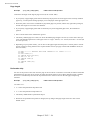
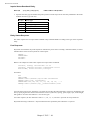
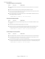
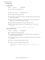
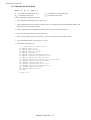
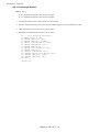
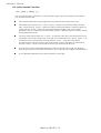
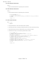
Text length
Esc&ll#F
(27)(38)(108)#(70)
<1Bh><25h><6Ch>#<46h>
# stands for the number of lines of text (at the current VMI) to be printed on each page.
• Values for # should be within the value (Logical Page length-Top margin).
• Text is printed from the top margin downwards.
• If you specify a value that would cause the text area to extend beyond the end of the logical page, the command
is ignored.
Top margin
Page length
Text length
Bottom margin
Chapter 2 "PCL" - 23
Revision C 16/01/96
Page length
Esc&ll#P
(27)(38)(108)#(80)
<1Bh><25h><6Ch>#<50h>
# stands for the length of the logical page in lines (at the current VMI).
• If you specify a page length greater than is allowed by the physical size of the paper in the currently installed
paper tray, a control panel message prompts you to load paper of the appropriate size.
• When the printer receives this command any unprinted pages are printed, and the left, right and top margins,
and the text length are set to their user defaults.
• If you specify a page length greater than is allowed by any of the supported paper sizes, the command is
ignored.
• If the current VMI is 0 the command is ignored.
• The factory default page size is letter, for which the default page length is 66 lines (11 inches with 6 lines per
inch). The default lengths for the other paper sizes are: Legal - 84 lines, A4 - 70 lines, Executive - 63 lines (all
at 6 lines per inch).
• Depending on your printer model, you can also set the page length from the printer’s control panel or remote
printer console by setting LINES to the required number of lines per page in the PAGE FORMAT mode (see
the User Guide).
10
20
30
40
50
60
70
80
90
REM ******* SETTING THE PAGE LENGTH TO 66 LINES *******
REM
ESC$=CHR$(27)
LPRINT ESC$+"&l66P";
FOR I=1 TO 67
LPRINT STR$(I)
NEXT
LPRINT CHR$(12);
END
Perforation skip
You can set the printer to flow text from one page to the next when it encounters a line feed (or half line feed) that
would otherwise move the cursor position to below the bottom of the text area. When perforation skip is enabled
the cursor is automatically moved to the top left hand corner of the text area on the next page and printing
continues.
Esc&ll#L
(27)(38)(108)#(76)
<1Bh><25h><6Ch>#<4Ch>
# is either 0 or 1.
• # = 0 turns the perforation skip feature off.
• # = 1 turns the perforation skip feature on.
• The factory default mode is perforation skip on.
• Whenever the perforation skip mode is changed, the top margin and page length values are reset to their
default values.
Chapter 2 "PCL" - 24
Revision C 16/01/96
Positioning the cursor
You can position the cursor anywhere on the logical page. In addition, the cursor position is automatically
changed when text or graphics are printed. You can either position the cursor using absolute PCL coordinate
values or position it relative to the current cursor position, using dots, decipoints or rows and columns as units. In
case of using dots, the units value is defined by the ESC & u # d command. The commands for positioning the
cursor are listed below.
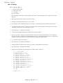
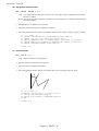
Vertical positioning
Vertical cursor positioning in Rows
Esc&a#R
(27)(38)(97)#(82)
<1Bh><26h><61h>#<52h>
# = number of rows
• A plus or minus sign preceding the number of rows parameter indicates that the cursor is to be positioned
relative to its current position. A signed positive parameter value signifies that the cursor is to be repositioned
vertically downwards on the page, a negative value means that it will be moved upwards.
• An unsigned number as the parameter signifies that the vertical repositioning is absolute - the cursor will be
repositioned the specified number of rows below the top margin, the PCL coordinate system’s x-axis.
• The parameter value can have up to two decimal places.
• The cursor’s horizontal position remains unchanged.
• If you attempt to move the cursor to a position that is outside the boundaries of the logical page, the cursor will
be positioned at either the top or bottom of the logical page as appropriate.
Units
Esc*p#Y
(27)(38)(112)#(89)
<1Bh><26h><70h>#<79h>
# = number of units
• Units value is defined by the Esc & u # D command.
• A plus or minus sign preceding the number of dots parameter indicates that the cursor is to be positioned
relative to its current position. A signed positive parameter value signifies that the cursor is to be repositioned
vertically downwards on the page, a negative value means that it will be moved upwards.
• An unsigned number as the parameter signifies that the vertical repositioning is absolute - the cursor will be
repositioned the specified number of dots below the top margin, the PCL coordinate system’s x-axis.
• The cursor’s horizontal position remains unchanged.
• If you attempt to move the cursor to a position that is outside the boundaries of the logical page, the cursor will
be positioned at either the top or bottom of the logical page as appropriate.
Chapter 2 "PCL" - 25
Revision C 16/01/96
Vertical cursor positioning in Decipoints
Esc&a#V
(27)(38)(97)#(86)
<1Bh><26h><61h>#<56h>
# = number of decipoints in 1/720"
• A plus or minus sign preceding the number of decipoints parameter indicates that the cursor is to be positioned
relative to its current position. A signed positive parameter value signifies that the cursor is to be repositioned
vertically downwards on the page, a negative value means that it will be moved upwards.
• An unsigned number as the parameter signifies that the vertical repositioning is absolute - the cursor will be
repositioned the specified number of decipoints below the top margin, the PCL coordinate system’s x-axis.
• The cursor’s horizontal position remains unchanged.
• If you attempt to move the cursor to a position that is outside the boundaries of the logical page, the cursor will
be positioned at either the top or bottom of the logical page as appropriate.
Horizontal position
Horizontal cursor positioning in Columns
Esc&a#C
(27)(38)(97)#(67)
<1Bh><26h><61h>#<43h>
# = number of columns
• A plus or minus sign preceding the number of columns parameter indicates that the cursor is to be positioned
relative to its current position. A signed positive parameter value signifies that the cursor is to be repositioned
to the right on the page, a negative value means that it will be moved to the left.
• An unsigned number as the parameter signifies that the horizontal repositioning is absolute - the cursor will be
repositioned the specified number of columns to the right of the left edge of the logical page, the PCL
coordinate system’s y-axis.
• The parameter value can have up to two decimal places.
• The cursor’s vertical position remains unchanged.
• If you attempt to move the cursor to a position that is outside the boundaries of the logical page, the cursor will
be positioned at either the left or right edge of the logical page as appropriate.
10 REM ***** HORIZONTAL CURSOR POSITIONING *****
20 ESC$=CHR$(27)
30 REM
40 REM --- POSITIONING CURSOR AT COLUMN 10 --50 LPRINT ESC$+"&a10C";
60 LPRINT "A";
70 REM --- MOVING CURSOR 5 COLUMNS TO THE LEFT --80 LPRINT ESC$+"&a-5C";
90 LPRINT "B";
100 REM --- MOVING CURSOR 10 COLUMNS TO THE RIGHT --110 LPRINT ESC$+"&a+10C";
120 LPRINT "C";
130 REM --- PAPER EJECT --140 LPRINT CHR$(12);
150 END
< Sample file 3 >
Chapter 2 "PCL" - 26
Revision C 16/01/96
Units
Esc*p#X
(27)(38)(112)#(88)
<1Bh><26h><70h>#<58h>
# = number of units
• Units value is defined by the Esc & u # D command.
• A plus or minus sign preceding the number of dots parameter indicates that the cursor is to be positioned
relative to its current position. A signed positive parameter value signifies that the cursor is to be repositioned
to the right on the page, a negative value means that it will be moved to the left.
• An unsigned number as the parameter signifies that the horizontal repositioning is absolute - the cursor will be
repositioned the specified number of dots to the right of the left edge of the logical page, the PCL coordinate
system’s y-axis.
• The cursor’s vertical position remains unchanged.
• If you attempt to move the cursor to a position that is outside the boundaries of the logical page, the cursor will
be positioned at either the left or right edge of the logical page as appropriate.
10 REM ***** HORIZONTAL CURSOR POSITIONING *****
20 ESC$=CHR$(27)
30 REM
40 REM --- POSITIONING CURSOR AT 1 INCH --50 LPRINT ESC$+"*p300X";
60 LPRINT "A";
70 REM --- MOVING CURSOR 0.5 INCHES TO THE LEFT --80 LPRINT ESC$+"*p-150X";
90 LPRINT "B";
100 REM --- MOVING CURSOR 1 INCH TO THE RIGHT --110 LPRINT ESC$+"*p+300X";
120 LPRINT "C";
130 REM --- PAPER EJECT --140 LPRINT CHR$(12);
150 END
< Sample file 4 >
Chapter 2 "PCL" - 27
Revision C 16/01/96
Horizontal cursor positioning in Decipoints
Esc&a#H
(27)(38)(97)#(72)
<1Bh><26h><61h>#<48h>
# = number of decipoints 1/720"
• A plus or minus sign preceding the number of decipoints parameter indicates that the cursor is to be positioned
relative to its current position. A signed positive parameter value signifies that the cursor is to be repositioned
to the right on the page, a negative value means that it will be moved to the left.
• An unsigned number as the parameter signifies that the horizontal repositioning is absolute - the cursor will be
repositioned the specified number of decipoints to the right of the left edge of the logical page, the PCL
coordinate system’s y-axis.
• The cursor’s vertical position remains unchanged.
• If you attempt to move the cursor to a position that is outside the boundaries of the logical page, the cursor will
be positioned at either the left or right edge of the logical page as appropriate.
10 REM ***** HORIZONTAL CURSOR POSITIONING *****
20 ESC$=CHR$(27)
30 REM
40 REM --- POSITIONING CURSOR AT 1 INCH --50 LPRINT ESC$+"&a720H";
60 LPRINT "A";
70 REM --- MOVING CURSOR 0.5 INCHES TO THE LEFT --80 LPRINT ESC$+"&a-360H";
90 LPRINT "B";
100 REM --- MOVING CURSOR 1 INCH TO THE RIGHT --110 LPRINT ESC$+"&a+720H";
120 LPRINT "C";
130 REM --- PAPER EJECT --140 LPRINT CHR$(12);
150 END
< Sample file 5 >
Chapter 2 "PCL" - 28
Revision C 16/01/96
Positioning the cursor using control codes
The carriage return, space, horizontal tab and backspace control codes can also be used to reposition the cursor
using the current VMI and HMI settings.
Using the cursor position stack
You can save and retrieve up to 20 cursor positions using the cursor position stack.
Esc&f#S
(27)(38)(102)#(115)
<1Bh><26h><66h>#<73h>
# = 0 or 1
• Setting # to 0 stores the current cursor position on the stack.
• Setting # to 1 retrieves the cursor position currently on the top of the stack and makes it the current cursor
position.
• Resetting the printer deletes all the positions from the stack.
Half line feed
Esc= (27)(61)
<1Bh><3Dh>
• This command moves the cursor down half a row as defined by the last VMI or line spacing command
(Esc&l#C).
Chapter 2 "PCL" - 29
Revision C 16/01/96
Logical page orientation
Esc&ll#O
(27)(38)(108)#(79)
<1Bh><26h><6Ch>#<4Fh>
# = 0, 1, 2 or 3
• This command sets the orientation of the logical page relative to the physical page.
• Values of # produce orientations as follows: 0 = portrait, 1 = landscape, 2=reverse portrait and 3 = reverse
landscape.
• Sending this command to the printer causes the page length, text length, top, left and right margins to be set to
their user default values. Any previously transmitted data is printed out and the cursor is positioned at the top
left hand corner of the text area on the next page.
• Portrait or landscape orientation can also be selected from the printer’s control panel.
• The factory default orientation is portrait.
X
(0,0)
"TEXT"
Y
Top margin
Physical page
Logical page
X
(0,0)
Portrait # = 0
Y
Landscape # = 1
Y
(0,0)
Physical page
Logical page
X
Top margin
Y
(0,0)
X
Reverse portrait # = 2
Chapter 2 "PCL" - 30
Reverse landscape
#=3
Revision C 16/01/96
Text direction
Esc&a#P
(27)(38)(97)#(80)
<1Bh><26h><61h>#<50h>
# = 0, 90, 180 or 270.
• This command changes the orientation of the logical page relative to the physical page, but without the side
effects of the logical page orientation command. Hence you can print text in different directions on the same
page.
• Values of # have the following effects: 0 = portrait, 90 = landscape, 180 = reverse portrait and 270 = reverse
landscape. The value specifies the angle through which the text direction is rotated counterclockwise.
• The cursor position remains at the same physical page position.
• All subsequent text is printed in the newly selected orientation.
• The PCL coordinate system and margin settings are rotated through the specified angle. Hence the cursor
coordinates will change.
• HP-GL/2 graphics images cannot be rotated using this command.
• The factory default orientation is portrait.
10 WIDTH "LPT1:",255
20 REM --- PRINTER RESET --30 LPRINT CHR$(27);"E";
40 REM --- MOVING CURSOR TO X=500, Y=500 --50 LPRINT CHR$(27);"*p500X";
60 LPRINT CHR$(27);"*p500Y";
70 REM --- 0 deg --80 LPRINT CHR$(27);"&a0P";
90 LPRINT "BROTHER ";
100 REM --- 90 deg --110 LPRINT CHR$(27);"&a90P";
120 LPRINT "BROTHER ";
130 REM --- 180 deg --140 LPRINT CHR$(27);"&a180P";
150 LPRINT "BROTHER ";
160 REM --- 270 deg --170 LPRINT CHR$(27);"&a270P";
180 LPRINT "BROTHER ";
190 REM --- PAPER EJECT --200 LPRINT CHR$(12)
210 END
Chapter 2 "PCL" - 31
Revision C 16/01/96
Using fonts
Introduction
A font is a collection of characters that have common characteristics, such as size, style and typeface, and which
ranges over a given set of symbols. For example, 12 point Tennessee Bold in the Roman-8 symbol set is a typical
HL Series font. Different sorts of fonts are used to create various typographic effects. Traditionally, large point size
sans serif typeface fonts, like Helsinki and Utah are used for document headlines while smaller fonts with serif
typefaces, like Tennessee and Portugal are used for body text. In LaserJet mode you can have access to a large
range of fonts that are already built in to the printer’s ROM, plus the facility for downloading more fonts from a
personal computer or plugging in font cards/cartridges or PCMCIA memory cards. When you select a font for
printing you will specify a number of characteristics which identify the font you require. The laser printer does its
best to print using the font you specified, but if amongst all its available fonts it does not have the exact one that
you specified, it will compromise and give you what it regards as the closest available font. Sometimes the results
will not be what you expected and you should exercise care in selecting fonts for printing.
In some instances the selection of a font will be handled automatically from your word processing software or
other applications package. In these cases you need only ensure that the correct font is available (that is, as a
standard font in the ROM, on cartridge/card or downloaded) and the application will do the rest. You do not need
to concern yourself with sending any escape sequences.
As well as using software commands you can also select fonts using the printer’s control panel. Consult the User
Guide for details.
Font types
There are two types of fonts supported by this HL Series printer in LaserJet mode - bitmap fonts and scalable fonts.
Bitmap fonts
The characters which make up a bitmap font are raster bit images of the relevant symbols. When text is printed
using the font it is nearly always monospaced and when you select the font you specify it by its typeface, pitch (the
number of characters printed per inch), height (point size) and symbol set.
Scalable fonts
The printer has many scalable fonts available as standard. The following table shows scalable fonts available for
model HL-1260. ( For the other models' resident fonts, please see the User's Guide.)
Intellifont Compatible Fonts:
1260
Albertville
Antique Oakland
PcBrussels
Oklahoma
Cleveland Condensed
Connecticut
Brougham
Guatemala
LetterGothic
Maryland
PcTennessee
PcBrussels
Utah
Utah Condensed
Medium, Extra Bold
Medium, Oblique, Bold
Light, Light italic, Demi, Demi italic
Medium, Oblique, Bold, BoldOblique
Medium, Oblique, Bold, Bold oblique
Antique, Italic, Bold, Bold italic
Medium, Oblique, Bold
Roman, Italic, Bold, Bold italic
Light, Demi, LightItalic, DemiItalic
Medium, Oblique, Bold, BoldOblique
Medium, Oblique, Bold, Bold oblique
Chapter 2 "PCL" - 32
ü
ü
ü
ü
ü
ü
ü
ü
ü
ü
ü
ü
ü
ü
660
ü
ü
ü
ü
ü
ü
ü
ü
ü
ü
ü
ü
ü
ü
Revision C 16/01/96
Microsoft Windows 3.1 TrueType Compatible Fonts:
Tennessee
Helsinki
BR Symbol
W Dingbats
Roman, Italic, Bold, Bold Italic
Medium, Oblique, Bold, BoldOblique
1260
ü
ü
ü
ü
660
1260
ü
ü
ü
ü
660
1260
660
BR-Script Fonts:
Atlanta
Copenhagen
Portugal
Calgary
Book, BookOblique, Demi, DemiOblique
Roman, Italic, Bold, Bold italic
Roman, Italic, Bold, Bold italic
MediumItalic
Brother Original FOnts:
Bermuda Script
German
US Roman
San Diego
ü
ü
ü
ü
You can select a font in any of these typefaces, specifying height (point size) and symbol set. Characters printed in
scalable fonts are always proportionally spaced - that is, the spacing between characters on a line depends on their
shapes. To add to the number of fonts available, you can buy scalable typeface cartridges/cards which you can
insert into the printer’s cartridge/card slots, and scalable typeface disks from which you can copy the typefaces into
the printer’s memory. You can also create your own downloadable scalable typefaces, using software commands.
Bound fonts
Bound fonts are the fonts which have only a single symbol set.
Unbound fonts
Unbound fonts are the fonts which have a large amount of symbols selected from complementary symbol index
(intellifont) or unicode symbol index (TrueType).
Font sources
Depending on your model, fonts available to the printer can be in one of three places, either in the printer’s ROM
as supplied from the factory, on a cartridge/card or on a PCMCIA memory card or in the printer’s RAM. RAM
fonts are downloaded from a personal computer.
Internal fonts
The printer comes with some bitmap fonts contained in its ROM and many scalable typefaces which can be used
to create scalable fonts.
Cards/Cartridges fonts
You can buy cartridge/card -based bitmap fonts and scalable typefaces. Plug the cartridge/card into one of the
printer’s cartridge/card slots and then select any font from them as if it were in the printer’s ROM. Depending on
your model, you can also save bitmap fonts and scalable typeface in the flash ROM memory and you can use it as
font card.
Downloadable fonts
You can buy diskettes containing fonts which can be copied directly to the printer using the DOS COPY
command. You can also design of your own fonts and download them to the printer.
One disadvantage of downloaded fonts is that they reside in the printer’s RAM memory. The printer also uses this
memory for composing the text and graphic output that it prints on the page. If the memory contains too many
fonts the printer may run out of memory. Since downloaded fonts are stored in the printer’s RAM they are lost
when the printer is switched off, and you must redownload them before you can use them again.
Chapter 2 "PCL" - 33
Revision C 16/01/96
Primary and secondary fonts
The printer maintains two sets of font characteristics which define its primary and secondary fonts. The primary
font is the one it will use by default, the secondary font can be selected instead. This facility enables you to have
two parallel font definitions that you can switch between easily without invoking long escape sequences. You can
select the primary and secondary fonts using PCL commands.
Depending on your model, you can also set any available fonts to be the printer’s user default primary and
secondary fonts using the printer’s control panel. Refer to the User Guide for instructions on how to do this.
The factory default settings for both primary and secondary fonts are Brougham 12 point, 10 cpi Roman 8.
Specifying the primary font
When you specify primary font characteristics you send escape codes with ‘(’ as the second character of the
sequence. This tells the printer that the font characteristic you are specifying applies to the primary font.
Specifying the secondary font
When you specify secondary font characteristics you send escape codes with ‘)’ as the second character of the
sequence. This tells the printer that the font characteristic you are specifying applies to the secondary font.
Selecting the default fonts
To set the primary font settings to those of the printers default font and discard all the software settings you have
made in the meantime, send the printer the following escape sequence:
Esc(3@ (27)(40)(51)(64)
<1Bh><28h><33h><40h>
To set the secondary font settings to those of the printers default font send:
Esc)3@ (27)(41)(51)(64)
<1Bh><29h><33h><40h>
Switching between the primary and secondary fonts
To select the primary font as the font for printing send the printer the SI control code:
SI
(15)
(0F)
To select the secondary font as the font for printing send the printer the SO control code:
SO
(14)
(0E)
Criteria for font selection
The printer will try to match your stated font requirements as best it can with the fonts available to it in the three
font locations. In most cases you will be specifying a font you know to be present in one of the locations and the
resulting printed text will appear exactly as you envisaged. However, if you specify a particular combination of
font characteristics that is not possible, the printer will produce the closest possible match that it can by satisfying
the following specifications in the order: the symbol set, spacing type, pitch (for monospaced fonts), the height,
the stroke weight and the style. The meanings of each of these are explained in the following sub-sections.
Likewise, if you simply specify a font attribute that is not available, for example if you request a Utah Light font
when only Utah Medium and Utah Bold are available in the font locations, the printer will simply ignore the
requirement (light stroke weight, in this case) that it cannot fulfill.
Symbol set
The symbol set is the list of symbols that constitute a particular font. Normally symbol sets contain lower and
upper case letters, numbers, punctuation marks and a selection of other commonly used symbols. Some symbol sets
are designed for specific needs, for example, for generating text with mathematical expressions. The symbol set
has the highest priority of all the characteristics you specify when you designate the font you require. If the symbol
set you choose is available, but not in conjunction with any of the other characteristics you specify, the printer will
satisfy your symbol set request at the expense of the rest of your designation and the text printed out may well look
completely different from what you expected to see.
Chapter 2 "PCL" - 34
Revision C 16/01/96
Symbol collections
The symbol collections contain many symbols and a symbol set is made from symbol collections by selecting the
required symbols for unbound fonts. As symbol collections have more symbols than symbol sets, unbound fonts
can have more symbols than bound fonts. Due to the compatibility between symbol sets and symbol collections,
the printer searches the designated MSL or Unicode number by using a symbol set mapping table.
Type of character spacing
Character spacing is either fixed (monospacing), in which every printed character is allocated the same amount of
space on the line, or proportional, where characters are spaced according to their shape and size. For any serious
typographic work proportional spacing is essential since fixed spacing is unattractive and hard to read. In general
monospacing is used with bitmap fonts, and proportional spacing is used with scalable fonts. However,
proportionally spaced bitmap fonts do exist.
Pitch
Pitch is the number of characters that are printed per inch and therefore only applies to monospaced fonts. If you
make a pitch selection while using a proportionally spaced font the command will have no immediate effect.
However, the new pitch will be stored as part of the primary (or secondary) font designation and applied the next
time a monospaced font is selected as the primary (or secondary) font.
The printer’s in-built bitmap fonts all have a pitch of either 10, 12 or 16.66 characters per inch.
Height
Height refers to the height in points (1/72") of unaccented capital letters in a font. This is the generally accepted
method of defining the height of a font’s characters. Scaled fonts can be specified to an accuracy of 0.25 points.
Style
A font’s style is defined by its posture (upright or italic), width (condensed, normal or expanded) and structure
(solid, outline or shadow). Upright and italic bitmap fonts and scalable typefaces are available in the printer’s
ROM. However, these are all normal and solid fonts. To print using any of the other styles (for example, using
Condensed Helsinki, or Outline Tennessee) you would have to download the requisite font or install a font
card/cartridge containing it.
Stroke weight
Stroke weight refers to the thickness of the lines which make up the printed characters. Characters of normal line
thickness are called medium. Thicker lines are referred to as bold or black and thinner lines as light or thin. You
can specify 15 different stroke weights - 0 denotes medium weight, negative values signify thinner strokes, and
positive values signify bolder (thicker) strokes. If you have the bold font available that matches your font
designation, a stroke weight selection of 1 to 7 will produce bold text. Likewise, for light or thin text you would
need to make the requisite light or thin font available for the stroke weight selection to have any effect.
Typeface
Typeface refers to the designed style of the characters. Commonly known typefaces include Times, Helvetica,
Univers and Palatino. The printer has its own resident typefaces. When selecting a particular typeface ensure that
it meets all your other specified criteria, otherwise the printer will substitute a font of a different typeface that can
satisfy the other, higher priority criteria, such as style and stroke weight.
Chapter 2 "PCL" - 35
Revision C 16/01/96
Font selection commands
User-defined symbol sets
User-defined symbol sets can be used with Unbound scalable fonts. Three new commands below are prepared for
user-defined symbol set.
To define a symbol set, its ID code must be defined at first.
Next, a list of symbols for the symbol set must be downloaded.
Then, you can use the defined ID code for symbol set selection.
Symbol Set ID Code Command
Esc*c#R
(27)(42)(99)#(82)
<1Bh><2Ah><63h>#<52h>
• Value for # can be from 0 to 2047.
• This command defines the ID code for a user-defined symbol set which can be used to control symbol set
selection.
• The symbol set ID code defined by this command must be calculated by using the following formula.
Symbol Set ID Code = ( # x 32 ) + ( ID - 64 )
Symbol set selection values consists of numerical character(s) and alphabetical character.
For example, 8U is the symbol set selection value for Roman-8. In this case, the Symbol set ID code
is 277 as the result of the following calculation.
(8 x 32 ) + (85 - 64) = 277
• Make sure to select an unused number for a new ID code that you define. If the ID code has been used
already, the printer deletes the existing symbol set and defines the new symbol set.
Chapter 2 "PCL" - 36
Revision C 16/01/96
Define Symbol Set
Esc(f#W[data] (27)(49)(102)#(87)
<1Bh><28h><66h>#<57h>
• # value can be from 18 to 32767.
• # stands for number of bytes in the data which is followed this command.
• If an existing ID code is used for a user-defined symbol set, it is overwritten.
• Up to 2047 downloadable user-defined symbol sets can be stored subject to the printer's memory capacity.
• If a memory full error occurs while downloading the user-defined symbol set, the symbol set which is being
downloaded becomes invalid.
• The symbol set which is defined by this command is temporary stored in the printer memory.
• The data followed this command should be in the following format.
0-1
2-3
4-5
6-7
8-9
10 -
15
8
7
MSB
Header Size (18)
Encoded symbol set designator
Format
Symbol Set Type
First Code
Last Code
Character Requirements
Symbol Map [Last Code - First code + 1 ]
(B)
(UB)
(SB)
(UI)
(SI)
(ULI)
(SLI)
(ASC**)
Boolean
Unsigned Byte
Signed Byte
Unsigned Integer
Signed Integer
Unsigned Long Integer
Signed Long Integer
ASCII string array
0
LSB
(0,1)
(0 ~ 255)
( -128 ~ 127 )
( 0 ~ 65535 )
( - 32768 ~ 32767 )
( 0 ~ 232-1)
(-231 ~ 231 - 1)
(0 ~ **-1) of characters
0 -1: Header size (UI) - set to 18 or greater.
This value stands for the byte number of header.
2 -3 : Encoded Symbol Set Designator (UI) - should be as same as the ID code which is defined by ESC*c#R.
4:
Format (UB) - 1 for MSL (Intellifont), 3 for Unicode (TrueType).
5:
Symbol Set Type (UB) - 0, 1 or 2.
0 specifies a 7-bit font with character codes 20H to 7FH acceptable.
1 specifies a 8-bit font with character codes 20H to 7FH and 80H to FFH acceptable.
2 specifies 8-bit 256 all character fonts. Only when the printer is set to transparent print mode can the
characters 0, 7~15, 27 be printed.
6 - 7: First Code (UI) - indicates the first code of definition data followed this header.
8 -9: Last Code (UI) - indicates the last code of definition data followed this header. This value should be more
than the first code value. Also, the data followed this header should have (Last code - first code + 1) bytes.
Chapter 2 "PCL" - 37
Revision C 16/01/96
10 - 17:
Character Requirement Flag ( 8 bytes )
Used in conjunction with the character complement field in the header of the font descriptor, to decide the
compatibility of a symbol set for an unbound font. This flag indicates which symbol collections are
necessary to make the required symbol set.
Each bit in this field stands for the selection of each symbol collection. When set to 1, the symbol
collection is included and when set to 0, the symbol collection is not included in the unbound scalable font.
Character Requirements for MSL Symbol index
Bit
63
62
61
34
33
32
2,1,0
Value
1
0
1
0
1
0
1
0
1
0
1
0
000
Designated Use
Basic Latin required (such as ISO 8859/1 Latin 1)
Basic Latin not required
East European Latin required (such as ISO 8859/2 Latin 2)
Basic European Latin not required
Turkish required (such as ISO 8859/9 Latin 5)
Turkish not required
Math required (such as Math-8)
Math not required
Semi-graphic required (such as PC-8 D/N)
Semi-graphic not required
Dingbats required (such as ITC Zapf Dingbats series 100,series 200 )
Dingbats not required
MSL Symbol index
Character Requirements for Unicode Symbol index
Bit
31
30
29
28
27
26
25
24
23
22
2,1,0
Value
1
0
1
0
1
0
1
0
1
0
1
0
1
0
1
0
1
0
1
0
001
Designated Use
ASCII required (such as ISO 6 ASCII)
ASCII not required
West Europe extensions required (such as ISO 69 French)
West Europe extensions not required
East Europe extensions required (such as ISO 8859/2 Latin 2)
East Europe extensions not required
Turkish extensions required (such as ISO 8859/9 Latin 5)
Turkish extensions not required
Desktop Publishing extensions required (such as Windows 3.1)
Desktop Publishing extensions not required
Accent extensions required (such as ISO 8859/1 Latin 1)
Accent extentions not required
PCL extensions required (such as Roman-8)
PCL extensions not required
Macintosh extensions required (such as MC text)
Macintosh extensions not required
PostScript extensions required (such as PS Text)
PostScript extensions not required
Code Page extensions required (such as PC-8)
Code Page extensions not required
Unicode Symbol Index
Symbol Map (Array of UI )
The symbol map, which has a list of symbol index numbers, is used to define the symbols for the symbol set. This
map defines the combination between symbol index number and character code.
Chapter 2 "PCL" - 38
Revision C 16/01/96
Symbol set control command
Esc*c#S
(27)(42)(99)#(83)
<1Bh><2Ah><63h>#<53h>
• Values for # can be 0, 1, 2, 4, or 5.
• 0 specifies to delete all temporary and permanent user-defined symbol sets.
• 1 specifies to delete all temporary user-defined symbol sets.
• 2 specifies to delete current user-defined symbol set.
• 4 specifies to make current user-defined symbol set temporary.
• 5 specifies to make current user-defined symbol set permanent.
Selecting the symbol set
Esc(symbol set ID
(27)(40)
<1Bh><28h>
• This command selects the symbol set (character set) for the primary font.
• Symbol set IDs consist of a number followed by a letter.
• Default symbol set ID is Roman-8. If an invalid default symbol set ID is selected, the symbol set becomes
Roman-8.
• Selectable symbol set varies depending on your printer model.
Symbol set
ISO 60 : Norwegian 1
ISO 61 : Norwegian 2
ISO 4 : United Kingdom
Windows 3.1 Latin 2
ISO 25 : French
ISO 69 : French
HP German
ISO 21 : German
ISO 15 : Italian
Microsoft Publishing
Desk Top
HP Spanish
ISO 17 : Spanish
ISO 10 : Swedish
ISO 14 : JIS ASCII
ISO 85 : Spanish
PC Turkish
Legal
Roman 8
PC-8
PC-850
PC-852
MC Text
Set primary font
Esc(0D
Esc(1D
Esc(1E
Esc(9E
Esc(0F
Esc(1F
Esc(0G
Esc(1G
Esc(0I
Esc(6J
Esc(7J
Esc(1S
Esc(2S
Esc(3S
Esc(0K
Esc(6S
Esc(9T
Esc(1U
Esc(8U
Esc(10U
Esc(12U
Esc(17U
Esc(12J
Symbol set
ISO 57 : Chinese
ISO8859-1 (ECMA-94)
Latin 1
Wingdings
PS Math
Ventura Math
Math-8
Symbol
ISO 8859-2 Latin 2
ISO 8859-9 Latin 5
ISO 11: Swedish; names
PS Text
Ventura International
Ventura US
ISO 16 : Portuguese
ISO 84 : Portuguese
Windows 3.1 Latin 5
ISO 6 : ASCII
ISO 2 : IRV
Windows 3.0 Latin 1
PC-8 D/N
Pi Font
Windows 3.1 Latin 1
Chapter 2 "PCL" - 39
Set primary font
Esc(2K
Esc(0N
Esc(579L
Esc(5M
Esc(6M
Esc(8M
Esc(19M
Esc(2N
Esc(5N
Esc(0S
Esc(10J
Esc(13J
Esc(14J
Esc(4S
Esc(5S
Esc(5T
Esc(0U
Esc(2U
Esc(9U
Esc(11U
Esc(15U
Esc (19U
Revision C 16/01/96
User-defined symbol sets are available for the HL-10h, HL-1260 and HL-660. They are defined by the command
ESC ( f # W.
Esc)symbol set ID
(27)(41)
<1Bh><29h>
• This command selects the symbol set (character set) for the secondary font.
• To select any of the above symbol sets for the secondary font simply substitute ‘)’ for ‘(’ in the command
shown in the table.
10 REM ****** SELECT A CHARACTER SET ******
20 ESC$=CHR$(27)
30 WIDTH "LPT1:",255
40 REM --- ROMAN-8 CHARACTER SET SELECTION -----50 LPRINT ESC$+"(8U";
60 REM --- PRINT CHARACTERS ---70 FOR I=160 TO 255
80 LPRINT CHR$(I);
90 NEXT
100 LPRINT
110 REM --- PC-8 CHARACTER SET SELECTION -----120 LPRINT ESC$+"(10U";
130 REM --- PRINT CHARACTERS ---140 FOR I=160 TO 255
150 LPRINT CHR$(I);
160 NEXT
170 LPRINT
180 REM --- PAPER EJECT --190 LPRINT CHR$(12);
200 END
There is a further group of symbol sets that are available for Brother fonts only. You can select these as follows:
Esc(s#C
(27)(40)(115)#(67)
<1Bh><28h><73h>#<43h>
• This command selects the symbol set (character set) for the primary font.
Esc)s#C
(27)(41)(115)#(67)
<1Bh><29h><73h>#<43h>
• This command selects the symbol set (character set) for the secondary font.
• Brother symbol set IDs consist of a number only.
Symbol Set
Roman-8
US ASCII
German
UK English
French
Dutch
Italian
S. Spanish
A. English WP
UK ASCII/2
Symbol
International
American English
UK ASCII
Set primary font
Esc(s1C
Esc(s2C
Esc(s3C
Esc(s4C
Esc(s5C
Esc(s6C
Esc(s7C
Esc(s8C
Esc(s9C
Esc(s10C
Esc(s11C
Esc(s12C
Esc(s13C
Esc(s14C
Symbol set
Portuguese
Swiss German
American Spanish
Norwegian/Danish
Canadian
Finnish/Swedish
South African
PC-8 D/N
PC-8
PC-850
PC-860
PC-863
PC-865
Japanese English
Chapter 2 "PCL" - 40
Set primary font
Esc(s15C
Esc(s16C
Esc(s17C
Esc(s18C
Esc(s19C
Esc(s20C
Esc(s21C
Esc(s23C
Esc(s25C
Esc(s26C
Esc(s27C
Esc(s28C
Esc(s29C
Esc(s38C
Revision C 16/01/96
• To select any of the above symbol sets for the secondary font simply substitute ‘)’ for ‘(’ in the command
shown in the table.
10 REM ****** SELECTING CHARACTER SETS ******
20 ESC$=CHR$(27)
30 WIDTH "LPT1:",255
40 REM --- GERMAN CHARACTER SET SELECTION -----50 LPRINT ESC$+"(s3C";
60 REM --- PRINT CHARACTERS ---70 FOR I=33 TO 127
80 LPRINT CHR$(I);
90 NEXT
100 LPRINT
110 REM --- FRENCH CHARACTER SET SELECTION -----120 LPRINT ESC$+"(s5C";
130 REM --- PRINT CHARACTERS ---140 FOR I=33 TO 127
150 LPRINT CHR$(I);
160 NEXT
170 LPRINT
180 REM --- PAPER EJECT --190 LPRINT CHR$(12);
200 END
Selecting the type of character spacing
Esc(s#P (27)(40)(115)#(80) <1Bh><28h><73h>#<50h>
• This command selects the spacing type for the primary font.
Esc)s#P
(27)(41)(115)#(80)
<1Bh><29h><73h>#<50h>
• This command selects the spacing type for the secondary font.
•
# = 0 selects fixed spacing and # = 1 selects proportional spacing.
10 REM ****** SELECTING A PROPORTIONAL OR FIXED SPACE FONT ******
20 ESC$=CHR$(27)
30 WIDTH "LPT1:",255
40 REM --- SELECT A PROPORTIONALLY SPACED FONT ---50 LPRINT ESC$+"(s1P";
60 FOR I=33 TO 127
70 LPRINT CHR$(I);
80 NEXT
90 LPRINT
100 REM --- SELECT A FIXED SPACE FONT --110 LPRINT ESC$+"(s0P";
120 FOR I=33 TO 127
130 LPRINT CHR$(I);
140 NEXT
150 LPRINT
160 REM --- PAPER EJECT --170 LPRINT CHR$(12);
180 END
Chapter 2 "PCL" - 41
Revision C 16/01/96
Selecting the pitch
Esc(s#H (27)(40)(115)#(72) <1Bh><28h><73h>#<48h>
• This command designates the pitch for the primary font.
Esc)s#H (27)(41)(115)#(72) <1Bh><29h><73h>#<48h>
• This command designates the pitch for the secondary font.
• # = the number of characters to be printed per inch. However, the actual size range is defined in combination
with the character height.
• The printer’s in-built bitmap fonts all have a pitch of either 10, 12 or 16.66 characters per inch, and you can
specify any of these as follows:
Esc&k0S
( 10 cpi )
Esc&k2S
( 16.66 cpi )
Esc&k4S
( 12 cpi )
• The selection will apply to whichever font you are currently specifying (primary or secondary).
• If the printer doesn't have the specified size of font, the next largest size of font is used. If the printer doesn't
have a larger sized font, the next smallest one is used.
• This value is ignored by the printer when a proportional spaced font is selected.
10 REM ****** CHARACTER PITCH SELECTION ******
20 ESC$=CHR$(27)
30 WIDTH "LPT1:",255
40 REM --- SELECT A 10 CPI PITCH FONT ---50 LPRINT ESC$+"(s10H";
60 FOR I=33 TO 127
70 LPRINT CHR$(I);
80 NEXT
90 LPRINT
100 REM --- SELECT A 12 CPI PITCH FONT --110 LPRINT ESC$+"(s12H";
120 FOR I=33 TO 127
130 LPRINT CHR$(I);
140 NEXT
150 LPRINT
160 REM --- PAPER EJECT --170 LPRINT CHR$(12);
180 END
Selecting the height
Esc(s#V (27)(40)(115)#(86) <1Bh><28h><73h>#<56h>
• This command designates the height of the primary font.
Esc)s#V (27)(41)(115)#(86) <1Bh><29h><73h>#<56h>
• This command designates the height of the secondary font.
• # is the size in points (1/72") from 0.25 to 999.75 in 0.25 increments.
• This value is ignored by the printer when a fixed-spaced scalable font is selected.
Chapter 2 "PCL" - 42
Revision C 16/01/96
Scaling the scalable fonts vertically or horizontally
EscCR!#H (27)(13)(33)#(72) <1Bh><0Dh><21h>#<48h>
• This command designates the height of the scalable fonts.
EscCR!#V (27)(13)(33)#(86) <1Bh><0Dh><21h>#<56h>
• This command designates the width of the scalable fonts.
• # can be from 0.25 ~ 3.00 in 0.01 increments.
• # value is set to 0.25 when # is specified less than 0.25, and # value is set to 3.00 when # is specified bigger
than 3.00.
• The value set by this command is initialized when the emulation change, Resetting, Test Printing, or Macro
overlay is executed.
Selecting the style
Esc(s#S (27)(40)(115)#(83) <1Bh><28h><73h>#<53h>
• This command designates the style of the primary font.
Esc)s#S (27)(41)(115)#(83) <1Bh><29h><73h>#<53h>
• This command designates the style of the secondary font.
• If you select a particular style (for example upright condensed outline) the command will only take effect if the
font is available in one of the three font locations.
Value
0
1
4
5
8
24
32
64
128
160
Font Style
Upright & solid
Italic
Condensed
Condensed italic
Compressed, or extra condensed
Expanded
Outline
Inline
Shadowed
Outline shadowed
10 REM ****** PRINT IN ITALIC & UPRIGHT STYLE ******
20 ESC$=CHR$(27)
30 WIDTH "LPT1:",255
40 REM --- PRINT USING AN ITALIC FONT ---50 LPRINT ESC$+"(s1S";
60 REM --- PRINT FONT ---70 FOR I=33 TO 127
80 LPRINT CHR$(I);
90 NEXT
100 LPRINT
110 REM --- PRINT USING AN UPRIGHT FONT --120 LPRINT ESC$+"(s0S";
130 REM --- PRINT FONT ---140 FOR I=33 TO 127
150 LPRINT CHR$(I);
160 NEXT
170 LPRINT
180 REM -- PAPER EJECT --190 LPRINT CHR$(12);
200 END
Chapter 2 "PCL" - 43
Revision C 16/01/96
Selecting the stroke weight
Esc(s#B (27)(40)(115)#(66) <1Bh><28h><73h>#<42h>
• This command designates the stroke weight of the primary font.
Esc)s#B (27)(41)(115)#(66) <1Bh><29h><73h>#<42h>
• This command designates the stroke weight of the secondary font
• # is an integer between –7 and 7. A value of 0 signifies a medium stroke weight, negative numbers signify thin
or light stroke weights and positive numbers signify bold stroke weights.
• If you select a light or bold stroke weight the command will only have an effect if the font is available in one of
the three font locations.
Selecting the typeface
Esc(s#T (27)(40)(115)#(84) <1Bh><28h><73h>#<54h>
• This command designates the typeface of the primary font.
Esc)s#T (27)(41)(115)#(84) <1Bh><29h><73h>#<54h>
• This command designates the typeface of the secondary font.
• If the typeface you specify is not available in any of the three font source locations the printer will substitute a
font of a different typeface.
• The available values vary with the printer model. The following table shows the value for each typeface and
availability.
Typeface
Albertville
Antique Oakland
Brougham
Cleveland Condensed
Connecticut
Guatemala Antique
LetterGothic
Maryland
Oakland
PC Brussels
PC Tennessee
Utah
Set primary font Set secondary font
Esc(s4362T
Esc)s4362T
Esc(s4168T
Esc)s4168T
Esc(s4099T
Esc)s4099T
Esc(s4140T
Esc)s4140T
Esc(s4116T
Esc)s4116T
Esc(s4197T
Esc)s4197T
Esc(s4102T
Esc)s4102T
Esc(s4297T
Esc)s4297T
Esc(s4113T
Esc)s4113T
Esc(s4143T
Esc)s4143T
Esc(s4101T
Esc)s4101T
Esc(s4148T
Esc)s4148T
6V
10V
*
*
*
*
*
*
10h
*
*
*
*
*
*
*
*
*
*
*
*
660
*
*
*
*
*
*
*
*
*
*
*
*
1260
*
*
*
*
*
*
*
*
*
*
*
*
*
*
*
*
*
*
*
*
BR Symbol
Helsinki
Tennessee
W Dingbats
Esc(s16686T
Esc(s16602T
Esc(s16901T
Esc(s31402T
Esc)s16686T
Esc)s16602T
Esc)s16901T
Esc)s31402T
*
*
*
*
Atlanta
Calgary
Copenhagen
Portugal
Esc(s155T
Esc(s159T
Esc(s157T
Esc(s158T
Esc)s155T
Esc)s159T
Esc)s157T
Esc)s158T
*
*
*
*
Letter Gothic16.66
Brougham
OCR-A
Esc(s130T
Esc(s128T
Esc(s104T
Esc)s130T
Esc)s128T
Esc)s104T
Chapter 2 "PCL" - 44
*
*
*
*
*
*
*
*
*
*
*
*
*
*
Revision C 16/01/96
OCR-B
Esc(s110T
Esc)s110T
Bermuda Script
Germany
San Diego
US Roman
Esc(s134T
Esc(s132T
Esc(s133T
Esc(s135T
Esc)s134T
Esc)s132T
Esc)s133T
Esc)s135T
*
*
*
*
*
*
*
Font orientation
The printer’s built-in fonts are all portrait fonts. If you switch the orientation of the logical page to landscape and
select a font, the printer will automatically create the landscape font in its memory. This saves you having to make
the landscape font available by installing a card/cartridge or by downloading the font, but takes up printer memory
and may cause the printer to run out of space when trying to compose complex page layouts.
Transparent print data
Esc&p#X (character codes)
(27)(38)(112)#(88)
<1Bh><26h><70h>#<58h>
• This command enables you to print characters which are normally unprintable.
• # is the number of bytes of data that follow the command.
• Each byte of data is interpreted as a character code and the corresponding character in the currently selected
symbol set is printed (if there is one). You can use this command to print the symbols in the character set
which do not appear on the keyboard.
• If there is no character in the current symbol set corresponding to a specified code, a space is printed.
• The command is useful when using character sets like the IBM All Character Set in which every single code
has a corresponding character.
• Any control codes within the data will have no effect. The control code byte is treated as a character code.
Underlining text
Esc&d#D
(27)(38)(100)#(68)
<1Bh><26h><64h>#<44h>
• This command enables the underline facility.
• This command disables the underline facility.
• # is either 0 or 3. A value of 0 signifies fixed underlining, 3 specifies floating underlining.
• Fixed underlining means that the underline is drawn in the same place for all the characters of a particular
font.
• Floating underlining means that the underline is drawn in the same place for all the characters on a particular
line.
Esc&d@
(27)(38)(100)(64)
<1Bh><26h><64h><40h>
Chapter 2 "PCL" - 45
Revision C 16/01/96
Downloadable font manipulation
Fonts that you have bought on diskette can be downloaded to the printer from diskette or hard disk using the DOS
COPY command or a font downloading applications program. To create your own fonts you can use PCL
commands to send the various blocks of data that comprise a downloadable font. There are also a number of PCL
commands that enable you to manage fonts that you have already downloaded (both those that you have bought
and those you may have created yourself).
If you are using commercially available fonts consult the documentation that came with them for information on
how best to send them to the printer.
Font ID
Esc&*c#D (27)(38)(42)(99)#(68)
<1Bh><26h><2Ah><63h>#<44h>
• This command identifies the numerical ID of the font on which subsequent operations will be performed.
• # is the font ID number.
• Use this command to specify the ID number of a font that you are about to download, or of a font already in
printer memory that you want to perform a particular operation on it.
• If you specify the number of a font that already exists in memory and then download a new font from your
computer, the new font will overwrite the original font and assume the ID number that you specified.
Operations on downloaded fonts
Esc*c#F
(27)(38)(42)(99)#(70)
<1Bh><26h><2Ah><63h>#<46h>
• This command performs an operation on one or more downloaded fonts.
• # identifies the operation to be performed.
• # = 0 Delete all downloaded fonts from the printer’s memory.
• # = 1 Delete all temporary fonts from the printer’s memory.
(Fonts can be made permanent so as to be saved when the printer is reset - see below).
• # = 2 Delete the font (whose ID number was most recently specified) from the printer’s memory.
• # = 3 Delete the character (whose character code was most recently specified) from the font (whose ID number
was most recently specified).
(The command for specifying a character code is given in the section entitled Creating Downloadable
Fonts).
• # = 4 Make the font (whose ID number was most recently specified) temporary
• If # = 5 Make the font (whose ID number was most recently specified) permanent
• If # = 6 Make/Assign a copy of the current font (primary or secondary) with the last specified ID number.
• If # = 1026 Delete the font (whose ID number was most recently specified) from the installed PCMCIA card.
• If # = 1028 Delete all download fonts in the installed PCMCIA card
• If # = 1029 Save the font (whose ID number was most recently specified) into the installed PCMCIA card.
(All download fonts on PCMCIA card are permanent fonts.)
• #=1026, 1028, 1029 is available only when the PCMCIA memory card is installed to HL-1260 & HL-10h.
Chapter 2 "PCL" - 46
Revision C 16/01/96
Selecting a downloaded font
Esc(#X
(27)(40)#(88)
<1Bh><28h>#<58h>
• This command selects a downloaded font as the primary font.
Esc)#X
(27)(41)#(88)
<1Bh><29h>#<58h>
• This command selects a downloaded font as the secondary font.
• # is the ID number of the downloaded font.
Creating downloadable fonts
Downloading
You can download existing fonts (that is, ones that you have bought or ones that you have created previously)
using either a font downloading application program or the DOS command
COPY/b <filename> PRN
In addition, some word-processing and DeskTop publishing programs will automatically download the fonts that
have been used in a document when that document is printed.
Alternatively, you can create a new downloadable font and download the necessary blocks of data that comprise
the downloadable font using PCL commands.
To send a font, you must send
* a font descriptor block followed by the character code
* a character descriptor
* data for each character
The printer can download 3 types of fonts.
Bitmapped fonts, Bound Scalable fonts, and Unbound scalable fonts.
Sending the font descriptor
Esc)s#W (font descriptor data) (27)(40)(115)#(58) <1Bh><28h><73h>#<88h>
•
This command sends the font descriptor to the printer.
•
# should be in the range 0 to 32767.
•
# is the number of bytes in the descriptor.
•
Characters are designed on a notional grid known as the character cell. The positioning and shape of each
character on the grid defines its size, shape and alignment to the other characters in the font.
Chapter 2 "PCL" - 47
Revision C 16/01/96
Cell width
Cell height
Baseline distance
x-height
Baseline
Underline distance
Underline thickness
Chapter 2 "PCL" - 48
Revision C 16/01/96
• The Font descriptor has information for the whole character set. When this font descriptor is sent to the
printer with a font header to identify the font ID, the descriptor parameters become the basis of the downloaded
fonts.
• The data format for each type of font descriptor block is shown below.
< Bitmapped font > ··· This type of font descriptor is not recommended for HL-10h,1260 and 660.
Byte 15 (MSB)
8 7
(LSB) 0
0 Font Descriptor Size (64)
2 Descriptor Format (0)
Font Type
4 Style MSB
Reserved
6 Base Line Position
8 Cell Width
10 Cell Height
12 Orientation
Spacing
14 Symbol Set
16 Pitch (Default HMI)
18 Height
20 x-Height
22 Width Type
St
yle LSB
24 Stroke Weight T
ypeface LSB
26 Typeface MSB
Serif St
yle
28 Quality
Placement
30 Underline Distance
Underline Height
32 Text Height
34 Text Width
36 First Code
38 Last Code
40 Pitch Extended
Height Extended
42 Cap Height
44 - 47 Font Number
48 - 63 Font Name
64 Copyright (optional)
< Special Bitmapped font >
Byte 15 (MSB)
8 7
0 Font Descriptor Size (68)
2 Descriptor Format (20)
Font Type
4 Style MSB
Reserved
6 Base Line Position
8 Cell Width
10 Cell Height
12 Orientation
Spacing
14 Symbol Set
16 Pitch (Default HMI)
18 Height
20 x-Height
22 Width Type
St
yle LSB
24 Stroke Weight T
ypeface LSB
26 Typeface MSB
Serif St
yle
28 Quality
Placement
30 Underline Distance
Underline Height
32 Text Height
34 Text Width
36 First Code
38 Last Code
40 Pitch Extended
Height Extended
42 Cap Height
44 - 47 Font Number
48 - 63 Font Name
64 X Resolution
66 Y Resolution
n Copyright (Optional)
Chapter 2 "PCL" - 49
(LSB) 0
Revision C 16/01/96
< Intellifont Scalable Bound font >
Byte 15 (MSB)
8 7
0 Font Descriptor Size (>80)
2 Descriptor Format (10)
Font Type
4 Style MSB
Reserved
6 Base Line Position
8 Cell Width
10 Cell Height
12 Orientation
Spacing
14 Symbol Set
16 Pitch (Default HMI)
18 Height
20 x-Height
22 Width Type
St
yle LSB
24 Stroke Weight T
ypeface LSB
26 Typeface MSB
Serif St
yle
28 Quality
Placement
30 Underline Distance
Underline Height
32 Text Height
34 Text Width
36 First Code
38 Last Code
40 Pitch Extended
Height Extended
42 Cap Height
44 - 47 Font Number
48 - 63 Font Name
64 Scale Factor
66 Master X Resolution
68 Master Y Resolution
70 Master Underline Position
72 Master Underline Thickness (Height)
74 OR Threshold
76 Global Italic Angle
Desc. size Global Intellifont Data Size
80 Global Intellifont Data
n Copyright (optional)
Reserved
Checksum
Chapter 2 "PCL" - 50
(LSB) 0
Revision C 16/01/96
< Intellifont Scalable Unbound font >
Byte 15 (MSB)
8
0 Font Descriptor Size (<88)
2 Descriptor Format (11)
4 Style MSB
6 Base Line Position
8 Cell Width
10 Cell Height
12 Orientation
14 Symbol Set
16 Pitch (Default HMI)
18 Height
20 x-Height
22 Width Type
24 Stroke Weight
26 Typeface MSB
28 Quality
30 Underline Distance
32 Text Height
34 Text Width
36 Reserved
38 Number of Contours (Characters)
40 Pitch Extended
42 Cap Height
44 - 47 Font Number
48 - 63 Font Name
64 Scale Factor
66 Master X Resolution
68 Master Y Resolution
70 Master Underline Position
72 Master Underline Thickness
74 OR Threshold
76 Global Italic Angle
78-85 Character Complement
Desc. Global Intellifont Data size
Size - 2
Desc. size Global Intellifont Data
n Copyright (optional)
Reserved
7
Font Type (10)
Reserved
Spacing
Style LSB
Typeface LSB
Serif Style
Placement
Underline Thickness
Height Extended
Checksum
Chapter 2 "PCL" - 51
(LSB) 0
Revision C 16/01/96
< TrueType Scalable Bound font >
Byte 15 (MSB)
8
7
(LSB) 0
0 Font Descriptor Size (>72)
2 Descriptor Format (15)
Font Type
4 Style MSB
Reserved
6 Base Line Position
8 Cell Width
10 Cell Height
12 Orientation
Spacing
14 Symbol Set
16 Pitch (Default HMI)
18 Height
20 x-Height
22 Width Type
Style LSB
24 Stroke Weight
Typeface LSB
26 Typeface MSB
Serif Style
28 Quality
Placement
30 Underline Distance
Underline Thickness
32 Text Height
34 Text Width
36 First Code
38 Last Code / Number of characters
40 Pitch Extended
Height Extended
42 Cap Height
44 - 47 Font Number
48 - 63 Font Name
64 Scale Factor
66 Master Underline position
68 Master Underline Thickness
70 Font Scaling Technology
Variety
72 [ additional data may be inserted here ]
Desc. size Segmented Font data
# - 2 Reserved
Checksum
• Attributes are in one of six numerical formats.
Unsigned integer (UI) 0 to 65535
Unsigned long integer (ULI) 0 to 232–1
Signed integer (SI) –32768 to 32767
Unsigned byte (UB) 0 to 255
Signed byte (SB) –128 to 127
Boolean 0 or 1
• Font descriptor size (UI) - the size in bytes of the font descriptor block. Minimum size values for each font
type are shown in the above figure.
• Descriptor format (UB) - format type of the font.
0
10
11
15
20
Bitmapped font
Intellifont bound scalable font
Intellifont unbound scalable font
TrueType bound scalable font
Special bitmapped font
Chapter 2 "PCL" - 52
Revision C 16/01/96
• Font type (UB) - specifies type of symbol set.
0
Bound font. A 7-bit font with character codes 20H to 7FH acceptable.
1
Bound font. A 8-bit font with character codes 20H to 7FH and 80H to FFH acceptable.
2
Bound font. 8-bit all character codes are printable. However, 00H, 07H to 0FH and 1BH are printable
only when the data is defined as transparent print data.
10
Unbound font. Character codes corresponding to MSL numbers are acceptable.
11
Unbound font. Character codes corresponding to Unicode numbers are acceptable.
When a 7-bit font or 8-bit font is selected, it is possible for codes 00H to FFH to load characters or delete
them. It is also possible to print the characters if they are defined as transparent print data.
• Style MSB (UW) - combined with the Style LSB to make the style word. The value of the style word is
calculated as follows: style word = posture + (4 width) + (32 structure).
Value
0
1
2
3
Posture
Upright
Italic
Alternate Italic
Reserved
Value
0
1
2
3
4
5
6
7
Width
Normal
Condensed
Compressed or Extra Condensed
Extra compressed
Ultra compressed
Reserved
Extended or Expanded
Extra Extended or Extra Expanded
Value
0
1
2
3
4
5
6
7
8-11
12-15
16
17
18-30
31
Structure
Solid
Outline
In-line
Contour
Solid with Shadow
Outline with Shadow
Inline with Shadow
Contour with Shadow
Patterned (Complex patterns, subject to type family )
Patterned with Shadow
Inverse
Inverse in Open Border
Reserved
Unknown structure
The reserved bits should be set to Zero.
• Baseline position (UI) Bitmap font -
Intellifont scalable TrueType scalable -
the height in dots from the top of the character cell to the baseline. The units of dots is
the same as the defined font resolution. This number can be in the range 0 to (cell
height - 1).
a Ycoordinate in the design cell.
the height in dots from the top of the character cell to the baseline. This should be set to
0.
Chapter 2 "PCL" - 53
Revision C 16/01/96
• Cell width (UI) - ignored by this printer. the width in dots of the character cell. This can be from 1 to 65535.
• Cell height (UI) - ignored by this printer. the height in dots of the character cell. This can be from 1 to 65535.
• Orientation (UB) - 0(portrait), 1(landscape), 2(reverse portrait) or 3(reverse landscape). Ignored by this printer.
• Spacing (B) - the type of spacing, 0 (fixed pitch) or 1 (proportional spacing).
• Symbol set (UI) - a symbol set ID consists of a number and a letter. The symbol set attribute value is calculated
as follows: symbol set = (32 x number) + (ASCII value of letter - 64). For example, Math-8 has the symbol set
ID ‘8M’ so it would be encoded as (32 x 8) + (77 – 64) = 269.
Symbol set name
Default Set
Line Draw-7
ISO 60: Danish/Norwegian
Roman Extensions
ISO 25: French
HP German
Greek-8
Hebrew-8
Microsoft Publishing
Document
Ventura International
ISO 14: JIS ASCII
ISO 57: Chinese
Korean-8
HP Block Characters
Line Draw-8
Tech-7
Ventura Math
ECMA-94 Latin 1 (ISO 8859/1)
ECMA-128 Latin 5 (ISO 8859/9)
OCR A
OCR M
APL (Bit Paired)
Cyrillic ASCII (ECMA-113/86,
PC Cyrillic
HP Spanish
ISO 10: Swedish
ISO 84: Portuguese
HP European Spanish
HP-GL Download
HP-GL Special Symbols
Thai-8
Legal
HP-GL Language Set
Roman-8
PC-8
PC-850
Pi Font
Arabic-8
Industrial 2 of 5 Barcode
Interleaved 2 of 5 Barcode
MSI/Plessey Barcode
UPC/EAN Barcode
Symbol set ID Symbol set name
0@
Math-7
0B
HP Large Characters (264x Terminals)
0D
ISO 61: Norwegian version 2
0E
ISO 4: United Kingdom
0F
ISO 69: French
0G
ISO 21: German
8G
Hebrew-7
8H
ISO 15: Italian
6J
DeskTop
8J
PS Text
13J
Ventura US
0K
ISO 13: Katakana
2K
Kana-8
9K
Line Draw-7 (Same as 0B)
1L
Tax Line Draw
8L
Math-7 (Same as 0A)
1M
PS Math
6M
Math-8
0N
ECMA-94 Latin 2 (ISO 8859/2)
5N
ECMA-113/88 Latin/Cyrillic
0O
OCR B
2O
APL (Typewriter Paired)
1P
Specials
0R
Cyrillic
3R
ISO 11: Swedish for Names
1S
ISO 17: Spanish
3S
ISO 16: Portuguese
5S
ISO 85: Spanish
7S
HP Latin Spanish
16S
HP-GL Drafting
18S
Turkish-8
0T
ISO 6: ASCII
1U
ISO 2: International Reference Version
5U
OEM-1
8U
Windows
10U
PC-8 D/N (Danish/Norwegian)
12U
PC-852
15U
Arabic (McKay’s version)
8V
3 of 9 Barcode
1Y
Matrix 2 of 5 Barcode
4Y
CODABAR Barcode
6Y
Code 11 Barcode
8Y
USPS Zip
Chapter 2 "PCL" - 54
Symbol set ID
0A
0C
1D
1E
1F
1G
0H
0I
7J
10J
14J
1K
8K
0L
2L
0M
5M
8M
2N
10N
1O
0P
xQ
1R
0S
2S
4S
6S
8S
17S
8T
0U
2U
7U
9U
11U
17U
0V
0Y
2Y
5Y
7Y
15Y
Revision C 16/01/96
• Pitch (UI) - This value defines the default spacing for each point size in 1/4 dots. Combined with Pitch
Extended to specify the pitch of the font in 1/1024 dots. This is available for fixed pitch font characters
including the space character, and the space character of proportional spacing fonts.
For example, in case of a 17 cpi font (at 600 dpi),
1 inch
17 chara.
600 dpi
1 inch
4
1
= 141.17646
the value of Pitch (UI) should be 141.
The remainder of 0.17646 is calculated as pitch extended:
0.17646
256
4
1
the value for pitch extended is 45.
= 45.17376
For Intellifont-scalable fonts only, the default HMI is calculated as follows.
Default HMI (in dots) = (300 x master design pitch x required point size) ÷
{Master x Resolution ÷(height x 8)}
Default HMI ( in dots ) =
(300 x master design pitch x required point size) ÷ {72.307 x scale factor}
• Height (UI) - specifies the height of the font in 1/4 dots. Combined with Height Extended to specify the height
of the font in 1/1024 dots. This value can be converted to the point size (1/72").
For example, in case of a 10 point font at 300 dpi,
4
300 dots
1
= 166.667
1
dots
1
inch
72
This value is normally set to 2000 for Intellifont and should be set to zero for TrueType fonts.
10 point
• x-height (UI) - ignored by this HL Series printer. This word specifies the height (for Bit mapped fonts) or the
distance from the baseline (for Scalable fonts) of a lower case ‘x’ in 1/4 dots.
• Width type (SB) - ignored by this HL Series printer. This byte specifies the fonts character width according to
the table below.
Value
–5
–4
–3
–2
0
2
3
Width type
Ultra compressed
Extra compressed
Compressed or Extra condensed
Condensed
Normal
Expanded
Extra expanded
• Style LSB (UB) - see Style MSB.
Chapter 2 "PCL" - 55
Revision C 16/01/96
• Stroke weight (SB) - valid values are from –7 to +7. 0 denotes the normal (Roman) stroke width, –7 is the
lightest possible stroke and 7 is the boldest.
Value
–7
–6
–5
–4
–3
–2
–1
0
1
2
3
4
5
6
7
Stroke Weight
Ultra thin
Extra thin
Thin
Extra light
Light
Demi light
Semi light
Medium, Book, or Text
Semi bold
Demi bold
Bold
Extra bold
Black
Extra black
Ultra black
• Typeface family (UB) – the typeface. This word is made up of the Typeface MSB and the Typeface LSB and
identifies the typeface by number.
Bits 0 to 11 specify the typeface family and bits 12 to 15 specify the vending company.
15
12 11
Typeface Family
Vendor
Value
0
1
2
3
4
5
0
Vendor
Reserved
Agfa Division, Miles Inc.
Bitstream Inc.
Linotype Company
The Monotype Corporation plc
Adobe Systems Inc.
The Typeface family number can be 0 to 4095. This value is calculated as follows;
(TrueType base value) + (Vendor value x 4096) = Typeface Family
<Previous Models>
The typeface word consists of four fields. Bits 0 to 8 specify the typeface family, bits 9 to 10 indicate the
version number, bits 11 to 14 identify the vending company, and bit 15 is always set to zero.
15
0
11 10
Vendor
9 8
0
Version Typeface Base Value
• Serif style (UB) Bitmapped font - ignored by this printer.
Scalable font - values for the lower 6 bits are ignored and values for the upper 2 bits indicates the serif style.
Bit 6 indicates sans serif and bit 7 indicates serif.
Chapter 2 "PCL" - 56
Revision C 16/01/96
• Quality (UB) - ignored by this HL Series printer. This byte specifies the fonts quality according to the
following table.
Value
0
1
2
Quality
Data processing
Near letter quality
Letter quality
• Placement (SB) - ignored by this HL Series printer. This byte specifies the placement of characters relative to
the baseline according to the following table.
Value
1
0
–1
Placement
Superior
Normal
Inferior
• Underline distance (SB) Bitmapped fonts - the distance in dots from the baseline to the underline. A positive value places the underline
above the baseline, a negative value places it below the baseline. A value of 0 places it on the baseline.
Scalable fonts - ignored by this printer. This value should be set to 0.
• Underline height (UB) - the height of underline itself.
Bitmapped fonts - this value is fixed at 3 dots.
Scalable fonts - ignored by this printer. This value should be set to 0.
• Text height (UI) - ignored by this HL Series printer.
This word specifies the spacing between successive lines of text in 1/4 dots for bitmapped fonts and in design
units for scalable fonts. This is normally about 1.2 times the fonts height.
• Text width (UI) - ignored by this HL Series printer.
This word specifies the average width of the fonts lowercase characters in 1/4 dots for bitmapped fonts and in
design units for scalable fonts.
• First code (UI) - ignored by this printer. This word specifies the character code of the first (lowest numbered)
printable character in the font.
• Last code (UI) - specifies the character code of the last (highest numbered) character in the font. If this value
is less than 255, it is recognized as 00FFH.
• Pitch extended (UB) - the fractional part of the character pitch. For a 17 cpi font the bytes value would be
calculated as follows:
1200/17 = 70.588
The Pitch byte takes the value 70.
Pitch Extended = 0.588 X 256 = 150 (rounded down).
( According to HP's manual, this should be set to 0.) This printer ignores the value for scalable fonts.
• Height extended (UB) - the fractional part of the height of the font. For a 10 point font the bytes value would be
calculated as follows:
1200 X 10/72 = 166.667, the Height byte takes the value 166
Height Extended = 0.667 X 256 = 170 (rounded down).
Point size = (character height x 256 + extended character height) x 300 / (72 x 1024)
( According to HP's manual, this should be set to 0.) This printer ignores the value for scalable fonts.
Chapter 2 "PCL" - 57
Revision C 16/01/96
• Cap height data (UI) - ignored by this HL Series printer. This word specifies for the font the distance between
the baseline and the top of an unaccented capital letter (for example, ‘H’), as a percentage of the font’s em rule,
‘—’.
• Font number (ULI) - ignored by this HL Series printer. This 4-byte field specifies the number assigned to the
font by the vending company. The number is stored as a hexadecimal value in the lower three bytes, bytes 44,
45 and 46.
• Font name (16 bytes) - ignored by this HL Series printer. This 16-byte field can be used to specify a name for
the font.
• X-Resolution (UI) - specifies the resolution in the X-scan direction.
This value can be 300 or 600 for bitmapped fonts, and is normally set to 2540 for Intellifont scalable fonts.
This is used for scaling the X-coordinates of font data to the required point size.
After scaling ( in dots ) =
(300 x the required point size x X-coordinate) ÷ {72.307 x scale factor (8782)}
After scaling ( in dots ) =
(300 x the required point size x X-coordinate) ÷ {Master X-resolution x (Height ÷ 8) }
• Y-Resolution (UI) - specifies the resolution in the Y-scan direction.
This value should be set to 300 or 600 dpi for special bitmapped fonts and is not available for Bitmapped font
and TrueType font.
This is normally set to 2540 for Intellifont -scalable fonts and is used for scaling the Y-coordinates of the font
data to the required point size.
This value is calculated as:
After scaling ( in dots ) = (300 x the required point size x Y-coordinate) ÷ (72.307 x scale factor (8782) )
After scaling ( in dots ) = (300 x the required point size x Y-coordinate) ÷
{Master Y-resolution x (Height ÷8)}
• Scale Factor (UI) - specifies the number of design units per Em. This value can be the unit for the metrics of
Intellifont / TrueType scalable fonts.
This is normally set to 8782 and calculated for Intellifont as follows:
• Scale factor x 72.307 = resolution x height ÷ 8
• This is normally set to 2048 for TrueType fonts.
• Master Underline position (UI) - Specifies the distance from the baseline to the top of the underline in design
units and this is an alternative for "Underline Position (bit 30)" only for scalable fonts.
• Master Underline height (UI) - specifies the height of the underline itself in design units and this is an
alternative for "Underline Thickness (bit 31)" only for scalable fonts.
• Font Scaling Technology (UB) - specifies the type of font scaling technology for any scalable fonts.
Value
0
1
Font scaling technology
Intellifont
TrueType font
• Variety (UB) - only for TrueType fonts, this value should be set to 0.
• OR (LRE) Threshold (UI) - specifies the pixel size in design units. This is switched on between scaling the font
and its rasterization.
• Global Italic Angle (SI) - specifies the italic angle as a tangent relative to the vertical. The value 0 makes
upright fonts.
Chapter 2 "PCL" - 58
Revision C 16/01/96
• Global Intellifont Data Size (UI) - indicates the size of the global Intellifont data block.
• Global Intellifont Data - includes the global intellifont data.
• Character Complement (Array of UB) - identifies the symbol set compatibility for unbound fonts used with the
Character Requirement flag in the symbol set descriptor.
MSL Symbol Index
Bit Field
58 - 63
55 - 57
52 - 54
50 - 51
48 - 49
3 - 47
0-2
Designated Use
Reserved for Latin fonts.
Reserved for Cyrillic fonts.
Reserved for Arabic fonts.
Reserved for Greek fonts.
Reserved for Hebrew fonts.
Miscellaneous uses (South Asian, Armerian, other alphabets,
bar codes, OCR, Math, PC Semi-graphics, etc.)
Symbol Index field. 111 - MSL Symbol Index
Unicode Symbol Index
Bit Field
32 - 63
28 - 31
22 - 27
3 - 21
0-2
Designated Use
Miscellaneous uses (South Asian, Armenian, other alphabets, bar
codes, OCR, Math, etc.)
Reserved for Latin fonts.
Reserved for platform / application variant fonts.
Reserved for Cyrillic, Arabic, Greek and Hebrew fonts.
Symbol Index field. 110 - Unicode Symbol Index
MSL Symbol Index Character Complement bits
Bit Field
63
62
61
34
33
32
Designated Use
0 if font is compatible with standard Latin character sets (e.g., Roman8, ISO 8859-1 Latin 1); otherwise set to 1.
0 if font is compatible with East European Latin character sets (e.g.,
ISO 8859-2 Latin 2); otherwise set to 1.
0 if font contains Turkish character sets (e.g., ISO 8859/9 Latin 5);
otherwise set to 1.
0 if font has access to the math characters of the Math-8, PS Math and
Ventura Math character sets; otherwise set to 1.
0 if font has access to the semi-graphic character of the PC-8, PC-850,
etc. character sets; otherwise set to 1.
0 if font is compatible with ITC Zapf Dingbats series 100, 200, etc.;
otherwise set to 1.
111 if font is arranged in MSL symbol Index order.
2,1,0
Chapter 2 "PCL" - 59
Revision C 16/01/96
Unicode Symbol Index Character Complement bits
Bit Field
31
30
29
28
27
26
25
24
23
22
Designated Use
0 if font is compatible with 7-bit ASCII; otherwise set to 1.
0 if font is compatible with ISO 8859/1 Latin 1 (West Europe)
character sets; otherwise set to 1.
0 if font is compatible with ISO 8859/2 Latin 2 (East Europe) character
sets; otherwise set to 1.
0 if font is compatible with Latin 5 (Turkish) character sets (e.g., ISO
8859/9 Latin 5,PC-Turkish); otherwise set to 1.
0 if font is compatible with Desktop Publishing character sets (e.g.,
Windows 3.1 Latin 1, DeskTop, MC Text); otherwise set to 1.
0 if font is compatible with character sets requiring a wider
selection of accents (e.g., MC Text, ISo 8859/1 Latin 1);
otherwise set to 1.
0 if font is compatible with traditional PCL character sets (e.g.,
Roman-8, Legal, ISO 4 United Kingdom); otherwise set to 1.
0 if font is compatible with the Macintosh character set (MS
Text); otherwise set to 1.
0 if font is compatible with PostScript Standard Encoding (PS Text);
otherwise set to 1.
0 if font is compatible with Code Pages (e.g., PC-8, PC-850,
PC-Turk, etc.); otherwise set to 1.
110 if font is arranged in Unicode Symbol Index order.
2,1,0
• Checksum - This should be set to a value which, when added to the contents of the 64 bytes of this font
descriptor data produces a total of 0.
• Descriptor size - segmented font data.
MSB
15
8
x First segment, segment identifier
x + 2 First segment, Segment size
x + 4 First segment, Data segment
7
x + 4 + 1st Second segment,segment identifier,
seg. size
|
# - 6 Null segment identifier
# - 4 Null segment size
# - 2 Reserved
LSB
0
Size, Data segment
|
Checksum
This segment follows just after the font header for TrueType. Each segment is divided into segment identifier,
segment size, and data segment parts.
Chapter 2 "PCL" - 60
Revision C 16/01/96
*Segment Identifier (UI) Each item in the data segment part has an identification number.
Value
17219
17232
18260
20545
22618
65535
Mnemonic
CC
CP
GT
PA
XW
Data Segment
Character Complement
Copyright
Global TrueType Data
Panose Description
X windows font name
Null Segment
*Segment Size (UI) - indicates the size of each item in the data segment.
*Data segment AP - Application support segment (reserved)
CC - Character Complement
Function and form are as same as character complement flag in the font descriptor. This is only for
unbound fonts.
CP - Copyright
Value should be ASCII data.
GI - Global Intellifont data (reserved)
GT - Global TrueType Data
This segment consists of a table directory and several tables for the TrueType font scaler.
The table directory consists of a 12-byte header and 16 bytes pen entry.
IF - Intellifont Face Data (Reserved)
PA - PANOSE Descriptor
This data segment is used for font selection and substitution.
PF - PS-compatible font name (Reserved)
XW - X-Windows font name
Sending a character code
Esc*c#E (character code)
(27)(42)(99)#(69)
<1Bh><2Ah><63h>#<45h>
• This command sends a character code for the bitmapped font ( MSL number for unbound fonts ) to the printer.
The font data must follow immediately.
• # is the character code. # can be from 0 to 65535. The specified character is defined by the data which follows
the character code.
• Use this command also to designate a character for deletion from a font, using the command for deleting a
character from a downloaded font.
Sending a character descriptor and data
Esc(s#W (character descriptor and character data)
(27)(40)(115)#(87)
<1Bh><28h><73h>#<57h>
• This command sends a character descriptor block and raster data describing the shape of the character to the
printer.
• # is the total number of bytes (descriptor and data) which will follow this command and can be up to 32767. If
you need to send more than 32767 bytes to describe a single character you must split it into blocks of 32767
bytes or fewer and send each block separately.
• The character header for the first block of data describing a character is in the following format.
Chapter 2 "PCL" - 61
Revision C 16/01/96
[Bitmapped font ]
Byte Data
0 - 1 Format
2 - 3 Descriptor size
4 - 5 Orientation
6 - 7 Left offset
8 - 9 Top offset
10 - 11 Character width
12 - 13 Character height
14 - 15 Delta X
16 - Raster Character Data
Continuation
Class
Reserved
< Bitmapped continuation data >
Byte
0-1
2
Format
Raster Character Data
Data
Continuation
• The bytes which follow the header are the raster data that make up the character.
• Attributes are in one of four numerical formats.
Unsigned integer (UI) 0 to 65535
Signed integer (SI) –32768 to 32767
Unsigned byte (UB) 0 to 255
Boolean - 0 or 1
• Format (UB) - 4 for bitmap fonts.
• Continuation (B) - signifies whether the character data represents a new character (0) or is a continuation of
the character described by the previous character descriptor block and its data (non-zero). If the continuation
byte is non-zero the bytes following it are interpreted as character data.
• Descriptor size (UB) - 14 for bitmap fonts.
• Class (UB) - 1 for bitmap fonts, 2 for compressed bitmap fonts. Bitmap fonts are described using uncompressed
raster data. Compressed bitmap fonts character data is encoded as follows. The first byte of a line of data
contains the number of times that the line is successively repeated. The second byte indicates the number of
successive white pixels that start the line and the third byte indicates the number of successive black pixels
that follow the white pixels. Subsequent even and odd numbered bytes indicate the number of successive white
and black pixels respectively that make up the line. If there are more than 255 successive pixels of a single
color this is indicated by a byte set to 255 followed by a byte set to 0 followed by a byte indicating the
remaining number of pixels of that colour. The width of each line is determined by the character width
attribute. All rows must contain the same number of pixels. The total number of pixels on each row must equal
the character width attribute.
• Orientation (UB) - the orientation of the character. 0 = portrait, 1 = landscape, 2 = reverse portrait or 3 =
reverse landscape. This attribute setting must match the orientation specified in the font descriptor block.
• Left offset (SI) - the distance between the character reference point and the leftmost dot of the character on the
grid. The offset can be from -16384 to 16383.
• Top offset (SI) - the distance between the character reference point and the topmost dot of the character on the
grid. The offset can be from -16384 to 16383.
• Character width (UI) - the width of the download character in grid dots. This can be in the range 1 to 16384.
Chapter 2 "PCL" - 62
Revision C 16/01/96
• Character height (UI) - the height of the download character in grid dots. This can be in the range 1 to 16384.
• Delta X (UI) - the horizontal distance from the bottom left hand corner of the character’s grid that the cursor is
moved after the character is printed. The attribute is specified in units of 1/1200" and can be in the range 32768 to 32767.
[ Intellifont scalable font data]
Byte
0-1
2-3
4-5
Last data
Format
Descriptor size
Contour Character data
Reserved
Data
Continuation
Class
Checksum
< Intellifont-scalable contour data>
MSB
4 Contour Data size
6 Metric data offset
8 Character Intellifont data
10 Contour tree offset
12 XY data offset
14
Metric data
Character Intellifont Data
Contour tree data
XY coordinate data
LSB
offset
< Continuation data for Intellifont scalable contour data >
Byte
Data
0-1 Format
Continuation
2 - 3 Continuous contour character data
Last Reserved
Checksum
< Compound character data of Intellifont scalable font >
Byte
Data
0-1 Format
Continuation
2 - 3 Descriptor size
Class
4 - 5 Compound character escapement
6 - 7 piled character number
ignore
8 - ... piled character list ( 6 byte x characters
)
Last Reserved
checksum
• Format (UB)
Value
4
10
15
- specifies the character format.
Format
Bitmapped font
Intellifont-scalable font
TrueType scalable font
• Continuation (B) - signifies whether the character data represents a new character (0) or is a continuation of
the character described by the previous character descriptor block and its data (non-zero). If the continuation
byte is non-zero the bytes following it are interpreted as character data.
• Descriptor size (UB) - specifies the character descriptor size in bytes.
Chapter 2 "PCL" - 63
Revision C 16/01/96
• Class (UB) . indicates the character format.
Value
1
2
3
4
15
Class
Bitmap
Compressed Bitmap
Contour (Intellifont scalable)
Compound Contour (Intellifont scalable)
TrueType Scalable
• Contour data size (UI) - specifies the contour data size.
• Metric Data offset (SI) - relative to the address of the coutour data size field.
• Contour Tree Offset (SI) -relative to the address of the coutour data size field.
• XY Data Offset (SI) -relative to the address of the contour data size field.
• Metric Data
• Character Intellifont Scalable Data
• Contour Tree Data
• XY Coordinate Data
• Checksum - this value is placed at the end of the character data.
• Compound character escapement (SI)
• Piled character number (UB)
• Piled character list - includes some piled characters. Each of them is 6 bytes.
[ TrueType scalable font ]
<TrueType character descriptor>
Byte
0-1 Format (15)
2 - 3 Descriptor size
4 ~ Additional descriptor size
2 + Desc.size Character Data Size
4 + Desc. size Glyph ID
6 + Desc. size TrueType Glyph Data
0-1
2-3
4~
2 + Desc.size
4 + Desc. size
6 + Desc. size
0-1
Last-2
Data
Continuation (0)
Class (15)
Format (15)
Continuation (0)
Descriptor size
Class (15)
Additional descriptor size
Character Data Size
Glyph ID
beginning of TrueType Glyph Data
Format (15)
TrueType Glyph Data
Continuation (1)
Reserved
Checksum
Chapter 2 "PCL" - 64
Revision C 16/01/96
• The character data follows these header bytes. Characters are represented as raster data and the data bytes are
used to build up an image of the character from left to right and from top to bottom, according to the character
width and height settings.
• Format (UB) - 15 specifies TrueType font.
• Continuation (B) - specifies whether the character data represents a new character (0) or is a continuation of
the character described by the previous character descriptor block (non-zero). If the continuation byte is nonzero the bytes following it are interpreted as character data.
• Descriptor size (UB) - specifies the character descriptor size in bytes.
• Class (UB) - indicates the character format.
Value
1
2
3
4
15
Class
Bitmap
Compressed Bitmap
Contour (Intellifont scalable)
Compound Contour (Intellifont scalable)
TrueType scalable
• Character data size (UI) - should be the same value as (the character data size + Glyph ID + TrueType Glyph
data) size.
• Glyph ID (UI) - specifies the ID number for glyph data, which is used by TrueType font scaler.
• TrueType Glyph data - includes the data segment which is associated with the given character as found in the
glyph table of the original TrueType font file.
• Checksum (UB) - should be a value which, when added to "Character data + Glyph ID + TrueType Glyph
data" size, produces a zero result.
Chapter 2 "PCL" - 65
Revision C 16/01/96
Portrait character
Paper motion
Raster scan
Top offset
= 22 dots
Baseline
Character height
= 31 dots
Cursor position after
character has been printed
Character reference
point
Left offset
= 2 dots
Character width = 26 dots
Delta X = 30 dots
Chapter 2 "PCL" - 66
Revision C 16/01/96
Landscape character
Paper motion
Top offset = 27 dots
Character height
= 26 dots
Raster scan
Left offset
= 22 dots
Baseline
Character width
= 31 dots
Cursor position after
character has been printed
Character reference
point
Delta X = 30 dots
Chapter 2 "PCL" - 67
Revision C 16/01/96
Using graphics
This HL Series printer affords the user considerable flexibility in the creation of graphic images. Vector, raster and
rectangle graphics are available, all of which allow a range of shading and filling options. The HP-GL/2 graphics
commands that are supported are described in the HP-GL/2 section of this manual.
Source, pattern and destination
We refer to a printing model in which a source image (the image to be drawn) is applied to a destination image
(simply the graphics or text that already exist on the page). The source image consists of white space and nonwhite areas. The non-white areas are covered by a pattern of some description. The pattern may simply be solid
black or it may itself consist of white and non-white areas, for example the pattern may consist of vertical spaced
lines. You can specify the way in which the white and dark areas of the entire source image and the white and
dark areas of the pattern interact with the destination image to produce the finished effect.
For example
Pattern
Source image
Destination image
Possible results
Chapter 2 "PCL" - 68
Revision C 16/01/96
Set source transparency
Esc*v#N
(27)(42)(118)#(78)
<1Bh><2Ah><76h>#<4Eh>
• This command sets the source image transparency.
• # is either 0 or 1. Set # to 0 to select transparent mode, and to 1 to specify opaque mode.
• Transparent mode means that parts of the destination image will be visible through the white space areas of the
source image when the source image has been printed on top of the destination image.
• Opaque mode means that parts the destination image will not be visible through the white space areas of the
source image when the source image has been printed on top of the destination image.
For example
Pattern
Source image
Destination image
With transparent
source image
With opaque
source image
Possible results
Chapter 2 "PCL" - 69
Revision C 16/01/96
Set pattern transparency
Esc*v#O
(27)(42)(118)#(79)
<1Bh><2Ah><76h>#<4Fh>
• This command sets the pattern transparency.
• # is either 0 or 1. Set # to 0 to select transparent mode, and to 1 to specify opaque mode.
• Transparent mode means that parts of the destination image will be visible through the patterned areas of the
source image when the source image has been printed on top of the destination image. If the pattern is a solid
black fill obviously you will not be able to see any of the destination image through the patterned areas of the
source image.
• Opaque mode means that the destination image will not be visible through the patterned areas of the source
image when the source image has been printed on top of the destination image.
For example
Pattern
Source image
(Source image is transparent)
Destination image
With transparent
pattern
With opaque
pattern
Possible results
Chapter 2 "PCL" - 70
Revision C 16/01/96
Set area fill identity
Esc*c#G
(27)(42)(99)#(71)
<1Bh><2Ah><63h>#<47h>
• This command sets the pattern ID of a shading tone, a fill pattern, or a user-defined pattern for subsequent
selection with the Set Pattern Type command.
• # 1 ~ 100 specify the percentage of a gray scale.
• # 1 ~ 6 select a fill pattern.
• # 1 ~ 32767 select a user-defined pattern.
• You can specify a gray scale tone from 1 to 100. To use the specified tone for shading you must then select one
of the two gray scale pattern options with the Set Pattern Type command.
For example
Fill patterns
#=1
#=2
#=4
#=5
#=3
#=6
User-defined pattern command
Esc*c#W [ data ]
(27)(42)(99)#(87)
<1Bh><2Ah><63h>#<57h>
• # should be in the range 0 ~ 32767.
• # stands for the number of pattern data bytes.
• User defined patterns can be defined by binary data or an 8 byte pattern descriptor.
• Here are the formats for the pattern descriptor.
< For 300 dpi >
MSB
0 - 1 Format (0)
2 - 3 Pixel Encoding (1)
4 - 5 Height in Pixels
6 - 7 Width in Pixels
8 - Pattern Image
LSB
Continuation (0)
Reserved (0)
Chapter 2 "PCL" - 71
Revision C 16/01/96
< For model HL-10h, HL-1260 and HL-660 >
MSB
0 - 1 Format (20)
Continuation (0)
2 - 3 Pixel Encoding (1)
Reserved (0)
4 - 5 Height in Pixels
6 - 7 Width in Pixels
8 - 9 X resolution
10 - 11 Y resolution
12 - Pattern Image
LSB
• A pattern which is defined at 600 dpi cannot be converted one at 300 dpi.
• Format - set to 0 or 20.
• Continuation - set to 0.
• Pixel Encoding - set to 1.
• Height in Pixels - specifies the pattern height by the number of rows.
• Width in Pixels - specifies the pattern width by the number of pixels.
• Pattern Image - consists of the raster data for the pattern.
• X resolution - specifies the resolution in the X scan direction.
• Y resolution - specifies the resolution in the Y scan direction.
Set pattern reference point
Esc*p#R
(27)(42)(112)#(82)
<1Bh><2Ah><70h>#<52h>
• This command sets the pattern reference point to the current cursor position.
• # specifies whether the pattern rotates with the print direction or remains fixed.
• The Pattern reference point should be placed on a physical page and the base pattern is positioned at the
pattern reference point for tiling.
User-defined pattern control
Esc*c#Q
(27)(42)(99)#(81)
<1Bh><2Ah><63h>#<51h>
• # = 0 deletes all (temporary and permanent) user-defined patterns from the printer memory.
• # = 1 deletes all temporary user-defined patterns from the printer memory.
• # = 2 deletes the pattern whose ID number was specified most recently.
• # = 4 saves the user-defined pattern as a temporary pattern, whose ID number was specified most recently.
• # = 5 saves the user-defined pattern as a permanent pattern, whose ID number was specified most recently.
Chapter 2 "PCL" - 72
Revision C 16/01/96
Set pattern type
Esc*v#T
(27)(42)(118)#(84)
<1Bh><2Ah><76h>#<54h>
• This command selects the fill pattern (black, white, gray scale or cross-hatch pattern) for use with subsequent
graphics operations.
• # is in the range 0 to 4 or 130.
• # = 0 selects solid black as the fill pattern.
• # = 1 selects white as the fill pattern (all source images will be completely white).
• # = 2 selects one of eight gray scales. Specify the gray scale you require as a percentage (0-100%) with the Set
Area Fill Identity command.
• # = 3 selects the cross-hatch pattern you choose with the Set Area Fill Identity.
• # = 4 selects the user-defined pattern
• # = 130 selects one of the 64 gray scales. You can specify the gray scale you require as a percentage (0-100%)
with the Set Area Fill Identity command. This feature is unique to this HL-Series printer.
0%
100%
#=130
3 - 10%
21-55%
56-80%
#=2
1- 2%
11 - 20 % 36-55%
81-99%
#=0
#=1
#=2
#=3
#=130
Chapter 2 "PCL" - 73
Revision C 16/01/96
Pattern example
10 WIDTH "LPT1:", 255
20 ESC$ = CHR$(27)
30 REM --- RESET PRINTER --40 LPRINT ESC$; "E";
50 REM --- SET SOURCE=TRANSPARENT --60 REM --- SET PATTERN=OPAQUE --70 LPRINT ESC$; "*v0n1O";
80 REM --- BACKGROUND --90 LPRINT ESC$; "*c80G"; ESC$; "*v2T";
100 LPRINT ESC$; "*p100x100Y"; ESC$; "*c1000a300b2P";
110 REM --- PATTERN --120 LPRINT ESC$; "*p150x300Y";
130 LPRINT ESC$; "(s1p48v0s0b4101T";
140 LPRINT ESC$; "*c1G"; ESC$; "*v3T"; : LPRINT "P";
150 LPRINT ESC$; "*c2G"; ESC$; "*v3T"; : LPRINT "A";
160 LPRINT ESC$; "*c6G"; ESC$; "*v3T"; : LPRINT "T";
170 LPRINT ESC$; "*c4G"; ESC$; "*v3T"; : LPRINT "T";
180 LPRINT ESC$; "*c5G"; ESC$; "*v3T"; : LPRINT "E";
190 LPRINT ESC$; "*c3G"; ESC$; "*v3T"; : LPRINT "R";
200 LPRINT ESC$; "*c1G"; ESC$; "*v3T"; : LPRINT "N";
210 REM --- PAPER EJECT --220 LPRINT CHR$(12);
230 END
<
Sample file 6
>
Plotting rectangles
Drawing rectangles is a basic case of printing graphics: the source image consists solely of the rectangle itself.
Thus only the pattern transparency has any bearing on the final effect - the source transparency is irrelevant.
Cursor position
Position the cursor using the commands described in the chapter entitled “The Page”. You can use units,
decipoints or rows and columns as coordinate units. Remember that the y-coordinate value goes up as the cursor
moves down the logical page.
Set rectangle width
Esc*c#A
(27)(42)(99)#(65)
<1Bh><2Ah><63h>#<41h>
• This command sets the width of the rectangle to be printed in dots.
• # is a number of dots.
Esc*c#H
(27)(42)(99)#(72)
<1Bh><2Ah><63h>#<48h>
• This command sets the width of the rectangle to be printed in decipoints.
• # is a number of decipoints.
Chapter 2 "PCL" - 74
Revision C 16/01/96
Set rectangle height
Esc*c#B
(27)(42)(99)#(66)
<1Bh><2Ah><63h>#<42h>
• This command sets the height of the rectangle to be printed in dots.
• # is a number of dots.
Esc*c#V
(27)(42)(99)#(86)
<1Bh><2Ah><63h>#<56h>
• This command sets the height of the rectangle to be printed in decipoints.
• # is a number of decipoints.
Draw filled rectangle
Esc*c#P
(27)(42)(99)#(80)
<1Bh><2Ah><63h>#<50h>
• This command fills a rectangular area with the specified shading option.
• # is 0 to 5 or 130.
• # = 0 uses solid black as the fill pattern.
• # = 1 uses white as the fill pattern.
• # = 2 selects the gray scale you chose with the Set Area Fill Identity command as the fill pattern.
• # = 3 selects the cross-hatch pattern you chose with the Set Area Fill Identity.
• # = 4 selects the user defined pattern, which is a specified ID number selected by the set Area Fill Identity.
• # = 5 uses the pattern specified by the combination of the most recent Set Area Fill Identity command and the
most recent Set Pattern Type command.
• # = 130 selects one of the sixty-four gray scales. You can specify the gray scale you require as a percentage (0100%) with the Set Area Fill Identity command. This feature is unique to this HL Series printer.
• See following two pages for programming examples using gray scales and patterns
#
0
1
2
3
4
5
130
Fill
Solid black
White
Gray scale (1 - 8)
Cross hatch pattern
User-defined pattern
Current pattern
Gray scale ( 1 - 64)
Chapter 2 "PCL" - 75
Revision C 16/01/96
Gray scale example
10 ESC$ = CHR$(27)
20 WIDTH "LPT1:", 255
30 REM --- DRAW A PATTERN USING 64 GRAY SCALES --40 X = 50: Y = 100: XL=50 :YL=200
50 FOR GRAY = 0 TO 100 STEP 2
60 GOSUB 220
70 X=GRAY*10+50 :XL=X-XL
80 GOSUB 260
90 XL=X
100 NEXT GRAY
110 REM --- DRAW A PATTERN USING 8 GRAY SCALES --120 Y=400
130 FOR GRAY = 0 TO 100 STEP 2
140 GOSUB 220
150 X=GRAY*10+50 :XL=X-XL
160 GOSUB 320
170 XL=X
180 NEXT GRAY
190 REM --- PAPER EJECT --200 LPRINT CHR$(12)
210 END
220 REM --- SET THE CURSOR POSITION --230 LPRINT ESC$; "*p"; X; "X";
240 LPRINT ESC$; "*p"; Y; "Y";
250 RETURN
260 REM --- PRINT 64-GRAY SCALE PATTERN --270 LPRINT ESC$; "*c"; XL; "A";
280 LPRINT ESC$; "*c"; YL; "B";
290 LPRINT ESC$; "*c"; GRAY; "G";
300 LPRINT ESC$; "*c130P";
310 RETURN
320 REM --- PRINT 8-GRAY SCALE PATTERN --330 LPRINT ESC$; "*c"; XL; "A";
340 LPRINT ESC$; "*c"; YL; "B";
350 LPRINT ESC$; "*c"; GRAY; "G";
360 LPRINT ESC$; "*c2P";
370 RETURN
< Sample file 7 >
Chapter 2 "PCL" - 76
Revision C 16/01/96
Raster graphics
Positioning the cursor
Position the cursor using the commands described in the chapter entitled “The Page”, using dots, decipoints or
rows and columns as coordinate units.
Set raster resolution
Esc*t#R
(27)(42)(116)#(82)
<1Bh><2Ah><74h>#<52h>
• This command sets the raster image resolution in dots per inch.
• # is 75, 100, 150, 200, 300 or 600.
• The lower the resolution you specify, the less printer memory your raster image will occupy.
• Use this command before you issue a Begin Raster Graphics command, otherwise the resolution that you
specify will not take effect until the next time you re-enter raster graphics mode.
Set high resolution control
EscCRRO
(27)(13)(82)(79)
<1Bh><0Dh><52h><4Fh>
• This command sets high resolution control off.
EscCRRL
(27)(13)(82)(76)
<1Bh><0Dh><52h><4Ch>
• This command sets high resolution control light level.
EscCRRM
(27)(13)(82)(77)
<1Bh><0Dh><52h><4Dh>
• This command sets high resolution control Medium level.
EscCRRD
(27)(13)(82)(68)
<1Bh><0Dh><52h><44h>
• This command sets high resolution control dark level.
Set raster image orientation
Esc*r#F
(27)(42)(114)#(70)
<1Bh><2Ah><72h>#<46h>
• This command specifies the orientation of the raster image.
• # is 0 or 3.
• # = 0 determines that the image will be printed from left to right and from top to bottom within the current
logical page.
• # = 3 determines that the image will be printed from left to right and from top to bottom within the current
physical page irrespective of logical page orientation.
Chapter 2 "PCL" - 77
Revision C 16/01/96
• The default value of # is 3.
X
Y
(X1,Y1) = Cursor position
(X1, Y1)
#=0
Y
X
(X1, Y1)
#=0
Landscape
Portrait
Y
X
(X1, Y1)
Y X
(X1, Y1)
#=3
#=3
Landscape
Portrait
Set raster area height
Esc*r#T
(27)(42)(114)#(84)
<1Bh><2Ah><72h>#<54h>
• This command sets the height of the raster image to be printed.
• # is the number of raster rows.
• If you use this command after using a Start Raster Graphics or a Transfer Raster Data command, it does not
take effect until after the next End Raster Graphics command.
Set raster area width
Esc*r#S
(27)(42)(114)#(83)
<1Bh><2Ah><72h>#<53h>
• This command sets the width of the raster image to be printed.
• # is the number of dots at the specified dots per inch resolution.
• If you use this command after using a Start Raster Graphics or a Transfer Raster Data command, it does not
take effect until after the next End Raster Graphics command.
Chapter 2 "PCL" - 78
Revision C 16/01/96
Set raster y-offset
Esc*b#Y
(27)(42)(98)#(89)
<1Bh><2Ah><62h>#<59h>
• This command sets the offset (number of blank rows to be skipped) for the raster image to be printed.
• # is the number of rows that are left blank at the top of the image.
• # must be in the range 0-32767
• This command is only effective in raster graphics mode, that is, after a Start Raster Graphics mode command.
Set compression mode
Esc*b#M
(27)(42)(98)#(77)
<1Bh><2Ah><62h>#<4Dh>
Identifies the method of compression used to encode the raster image that is to be sent to the printer.
•
# is 0, 1, 2, 3, 5, 9, 1152 or 1024.
•
# = 0 signifies no compression is to be used.
•
# = 1 indicates that run-length encoding is to be used. The raster data bytes are transmitted in pairs. The
second byte of each pair specifies the raster output: the first byte specifies the number of times the second byte
is successively repeated. A value of 0 for the first byte indicates a single occurrence of the second byte, a value
of 1 indicates two consecutive occurrences of the second byte and so on.
•
# = 2 indicates that TIFF (tagged image file format) encoding is to be used. In this format the data is
transmitted in groups of bytes. The first byte of each group is a control byte and defines how the subsequent
data byte or bytes should be interpreted, and how many data bytes there are before the next control byte. If the
two’s complement value of the control byte is in the range –1 to –127, the following byte is a repeated data
byte. The number of successive occurrences of the data byte is given by the absolute value of the control byte
plus one - that is if the control byte is -6, the following data byte is repeated 7 times. If the value of the control
byte is in the range 0-127 the bytes which follow are unencoded raster data. The number of data bytes is given
by the absolute value of the control byte plus one - that is if the control byte is 9, the following ten bytes are
unencoded data. If a control byte has the two’s complement value –128 it is ignored and the next byte is treated
as a control byte.
•
# = 3 indicates that delta row compression is to be used. In this method byte sequences identify how each raster
row differs from the last row that was transmitted. The first byte identifies a number of consecutive bytes (the
value of the senior 3 bits plus 1) to be changed and the position in the line at which to start substituting the
replacement bytes (the junior 5 bits plus 1). Hence, if the command byte has a 3 in the top three bits and 10 in
the bottom five bits, the 11th, 12th, 13th and 14th bytes of the last row will be replaced by the four data bytes
that follow.
If the junior 5 bits are all 1, the next byte is treated as a further offset value and its value is added to 32 to
calculate the offset. If this byte in turn is all ones the next byte is also treated as a continuation byte and its
value is added to the offset, and so on until a byte whose value is not 255 is encountered.
This combination of command bytes and replacement bytes is used to specify all the differences between the
last raster row sent (the seed row) and the new row to be transmitted. When the new row has been sent it
becomes the new seed row.
Chapter 2 "PCL" - 79
Revision C 16/01/96
• # = 5 indicates that adaptive compression is to be used.
This compression compresses multiple rows (block) into one transfer graphics command.
Most of other compression method compresses only one row to one transfer graphics command.
One transfer graphic command (ESC *b##W) can contain only up to 32,767 bytes.
As mode 5 compression compresses multiple rows, the amount of transferred data may become large.
If compressed data exceeds this limit, please reduce the number of rows in one block.
We can use mode 0 to mode 3 compression to compress each row. We can even compress empty (white) rows
and duplicate rows in this compression.
Command byte
Mode 5 compressed data consists of multiple elements. Each element contains 3 header bytes at the biginning.
The first byte of the header bytes is a command byte.
First byte
0
Unencoded
1
Run-length Encoding
2
TIFF
3
Delta Row compression
4
Empty Row
5
Duplicate Row
Second, third byte
Number of a block data
Number of empty row or repetition
Command byte
0-
This element is an uncompressed row. Next two bytes contain byte count of uncompressed data.
Uncompressed data follows the header.
1-
This element identifies compressed row. Compression method is mode 1. Next two bytes (upper
byte first) contain byte count of compressed data. Compressed data follows the header.
2-
This element identifies a compressed row. Compression method is mode 2. Next two bytes
(upper byte first) contain byte count of compressed data. Compressed data follows the header
3-
This element identifies a compressed row. Compression method is mode 3. Next two bytes
(upper byte first) contain byte count of compressed data. Compressed data follows the header
4-
This element identifies multiple empty rows. Next two bytes (upper byte first) contain empty
row count.
5-
This element identifies duplicate rows. Next two bytes (upper byte first) contain duplicate row
count.
• # = 9 Mode 9 compression
Like mode 3 compression, this compression (mode 9) data contains only the difference of the current row from
the preceding row.
Replacement data often consists of a repetition of a particular byte in mode 3 compression.
Mode 9 compression is effective in such cases.
Simple mode 9 compression data consists of a command byte and the replacement data.
A Command byte consists of 3 parts. They are the control bit, the offset count and the replacement count.
The Control bit is the most significant bit (bit 7) of a control byte.
Chapter 2 "PCL" - 80
Revision C 16/01/96
Command byte for mode 9 compression (non repeated replacement data)
7
6
5
4
3
2
1
0
0
Offset count
Replacement count-1
Control bit
If the control bit is 0, replacement data is not repeated data. Bits 6 to 3 contain the offset count. This field value
is from 0 to 15. If this value is 15, the next byte of the control bytes is an optional offset count. The value of
this optional offset count byte is from 0 to 255. If this optional offset count value is 255, then the next byte is
another (second) optional offset count byte. Optional offset count bytes will continue until the value is less than
255. The total Offset value is the sum of the offset count in the control byte and all the optional offset bytes.
Bits 2 to 0 of the control byte contains the replacement count - 1. The value is from 0 to 7. If this value is 7,
optional replacement byte(s) follow the control byte or optional offset byte(s) (if any).
If the first optional replacement count byte is 255, then a second optional count byte follows the first optional
count byte. Optional offset count bytes will continue until the value becomes less than 255. The addition of the
replacement count in the control byte and all optional replacement count bytes gives the total replacement
count.
Replacement data bytes follow the control byte and any optional offset bytes and any optional replacement
count bytes.
<Example>
Seed row
Current row
55 55 55 55 55 55 55 55 55 55 55 55 55
55 55 55 55 55 11 11 22 33 44 55 66 77
<Different section 11 11 22 33 44 55 66 77>
Offset count = 5
Replacement count = 8
Replacement data = 11 11 22 33 44 55 66 77
7
6
5
4
3
2
1
0
0
0
1
0
1
1
1
1
Optional offset count byte = 0
11 11 22 33 44 55 66 77
8 bytes of repracement data
Offset count = 5
Replacement count = 7 + 1 = 8
Command byte for mode 9 compression (repeated replacement data)
7
6
5
4
3
2
1
1
Offset count
Replacement count
Control bit
Chapter 2 "PCL" - 81
0
Revision C 16/01/96
If the control bit is 1, replacement data is repeated data. Bits 6 to 5 contain the offset count and bits 4 to 0
contain the 'replacement count(repeat count) - 2'.
If bit 6 and bit 5 are '1', then an optional offset byte follows the control byte. If the value of this optional offset
byte is 255, another (second) optional offset byte follows the first optional offset byte. The addition of the offset
count in the control byte and any optional offset bytes gives the total offset count.
If bits 4 to 0 are all '1', an optional replacement count byte follows the control byte or any optional offset
byte(s). If the first optional replacement count byte has a value of 255, a second optional replacement count
byte follows the first optional replacement count byte. Optional replacement count bytes will continue until the
value becomes less than 255.
<Example>
Seed row
Current row
55 55 55 55 55 55 55 55 55 55 55 55 55
55 55 55 11 11 11 55 55 66 66 66 66 55
<First section 11 11 11>
Offset count = 3
Replacement count = 3
Replacement data = 11
<Second section 66 66 66 66>
Offset count = 2
Replacement count = 4
Replacement data = 66
7
6
5
4
3
2
1
0
1
1
1
0
0
0
0
1
Optional offset count byte = 0
Replacement count = 1 + 2 = 3
Offset count = 3
7
6
5
4
3
2
1
0
1
1
0
0
0
0
1
0
Replacement data = 66
Replacement count = 2 + 2 = 4
Offset count = 2
Chapter 2 "PCL" - 82
Replacement data = 11
Revision C 16/01/96
•
# = 1152 indicates that CCITT G3/G4 data compression is to be used.
This format is popular in optical document storage area as this compression is effective to store black and
white type pictures. As G3/G4 format does not have picture size/resolution information, the printer requires a
header at the beginning of the picture data. The header size is 94 Byte. Bothe the header and the picture data
are transferred by the ESC*b###W(###=data length) command. Normal PCL transfer graphics data command
has a limitatino of the data size and ### should not exceed 32767. Unlike other mode, this mode is special
and does not have the 32767 size limitation. The data must have the following structure - Header and Picture
data. The values in this mode are little endians.
Header
94 bytes
Picture data
Picture
data
length
File Length
Byte
position
0-1
2-3
4-7
8 - 11
Data
Description
6E 6E
0A 00
5E 00 00 00
File length
12 - 13
14 - 15
16 - 19
20 - 21
01 00
01 00
4A 00 00 00
Compression mode
22 - 55
56 - 59
00 ... 00
Picture data length
60 - 61
62 - 63
64 - 65
66 - 67
68- 69
71 - 71
72 - 73
74 - 75
01 00
01 00
Pixels/line
Pixels/line
Lines/picture
Lines/picture
00 00
Photometrics 00 00
or 01 00
02 00
Fill order 01 00 or
02 00
01 00
00 00
01 00
Resolution 200,
300, 400, 600
'nn' This is header ID.
Reserved
Picture data start offset from header top
File length including 94 Byte header. If file length is 65,536
byte, these 4 bytes become "00 00 01 00"
Reserved
Reserved
Reserved
02 00: Fax MH format
03 00: Fax MR format
04 00: Fax G4 format
All zero
If picture data length is 65,442 (65,536 ~-94) byte, these 4 bytes
become "A2 FF 00 00."
bit / pixel
bit / pixel
If picture dot width = 2,400, these 2 bytes become "60 09"
Same as above.
If picture dot count = 3,100, these 2 bytes become "1C 0C."
Same as above.
Reserved
00 00 : data 0 = white
01 00 : data 0 = black
Reserved
01 00 : filled from MSB
02 00 : filled from LSB
Reserved
Reserved
Reserved
C8 00 00 00 : 200 dpi,
2C 01 00 00 : 300 dpi,
90 01 00 00 : 400 dpi,
58 02 00 00 : 600 dpi
400 and 600 dpi are available when printer operates in 600 dpi.
C8 00 00 00 : 200 dpi,
2C 01 00 00 : 300 dpi,
90 01 00 00 : 400 dpi,
58 02 00 00 : 600 dpi
400 and 600 dpi are available when printer operates in 600 dpi.
Reserved
Reserved
76 - 77
78 - 79
80 - 81
82 - 83
84 - 85
86 - 87
88 - 89
Resolution 200,
300, 400, 600
90 - 91
92 - 93
02 00
00 00
About CCITT G3/G4 data format, please refer to CCITT (The International Telegraph and Telephone
Consultative Committee) BLUE BOOK Volume VII.
Chapter 2 "PCL" - 83
Revision C 16/01/96
• # = 1024 indicates the TIFF format. This is valid only for 600 dpi data. The raster graphics data is transferred
with the ESC*b###W (### = data length) command. The TIFF file follows this mode set command. This
printer does not support LZW compression. Pages that contain TIFF data are printed in the gray scale mode.
The TIFF data contains the header, tag, and print data.
This mode supports TIFF Version 5.0 file format. In this mode, transfer graphics data command by te count
does not have a limitation of 32,767 byte. Ths printer supports bothe "MM" (big endian) format and "II" (little
endian) format. Print model is not applied to this type of data transfer. The printer has some limitations on
the TIFF format.
1. Tags position has to be prior to the picture (strip) data.
2. Compression tag - Tag ID : 259
The printer supports 1, 2, 3, 4 and 32773.
1 : no compression (Bits/Sample=1,4,8)
2 : CCITT G3 MH (Bits/Sample=1)
3 : CCITT G3 MR (Bits/Sample=1)
4 : CCITT G4 (Bits/Sample=1)
32773 : Pack Bits (Bits/Sample=1)
3. Sample/pixel - Tag ID : 277
This value should be 1. This means the printer accepts only monochrome TIFF file.
4. Bits/Smple - Tag ID: 258
The printer supports 1,4 and 8.
If you specify 4 or 8 and the printer resolution is 600 dpi, the printer prints that the page utilizing
APT.
5. Horizontal resolution (Tag ID=282) and Vertical resolution (Tag ID=283)
Compression type
No Compression
No Compression
Pack Bit
CCITT G3 & G4
Bits/Sample
4,8
1
1
Available Resolution
From 1 dpi to 300 dpi
Printer's Resolution
(300 or 600 dpi)
200,300,400,600 dpi
400 & 600 dpi are only when
printer operates in 600 dpi.
APT
ON
OFF
OFF
We recommend 150 dpi or less resolution for APT to reduce data size.
• # = 1025 indicates the Brother origianl Compression Method.
• # = 1026 indicates the Brother Advanced Data Transfer Mode.
Start raster transfer
Esc*r#A
(27)(42)(114)#(65)
<1Bh><2Ah><72h>#<41h>
• This command signals the start of the transfer of a raster image to the printer.
• # is 0 or 1.
• # = 0 denotes that the image will be printed starting from the left edge of the logical page.
• # = 1 denotes that the image will be printed starting from the current cursor position.
• The transfer of raster data to the printer continues until either an End Raster Transfer command is sent or a
command other than Send Raster Data, Set Compression Mode, or Set Raster Y-Offset is sent.
Chapter 2 "PCL" - 84
Revision C 16/01/96
Send raster data
Esc*b#W<data> (27)(42)(98)#(87) <1Bh><2Ah><62h>#<57h>
• This command sends a single row of the raster image to the printer for printing.
• # signifies the number of bytes to be sent.
• If more data is transmitted than can be fitted onto one row of the specified raster area, the excess data will be
ignored.
Compress transfer graphics
Esc*b#C<image data> (27)(42)(98)#(67) <1Bh><2Ah><62h>#<43h>
•
As a more efficient alternative to the Send Raster Data command, this command sends a single row of the
raster image to the printer for printing, in a compressed form.
•
# signifies the number of data bytes that the uncompressed row would consist of.
•
Pairs of bytes describe the data which follows.
•
If the MSB of the first byte of a pair is 1, the byte that follows the pair is repeated. The number held in the
remaining fifteen bits of the byte pair is the number of times the data byte is repeated.
•
If the MSB of the first byte of the pair is 0, the bytes that follow the pair are not repeated. The number held in
the remaining fifteen bits of the byte pair is the number of bytes of unrepeated raster data that follow.
• A raster row is made up of a sequence of byte pair-image data combinations.
End raster transfer
Esc*rB
(27)(42)(114)(66)
<1Bh><2Ah><72h><42h>
• This command signals the end of a transfer of a raster image to the printer.
• After execution of this command the cursor is positioned a distance of one raster row (at the last specified
number of dots per inch) down from the bottom of the raster area.
Esc*rC
(27)(42)(114)(67)
<1Bh><2Ah><72h><43h>
• This command signifies the end of the raster graphic data transfer and this is a modified version of the ESC
*rB.
• After receiving this command, the printer resets the compression seed, compression mode, and left-graphics
margin to 0.
• Also, the cursor is positioned a distance of one raster row (at the last specified number of dots per inch) down
from the bottom of the raster data.
• This command resets the compression mode setting to 0.
• This command defaults the left graphics margin to 0.
Chapter 2 "PCL" - 85
Revision C 16/01/96
Raster graphics example
10 REM ***** A EXAMPLE OF RASTER GRAPHICS *****
20 ESC$=CHR$(27)
30 WIDTH "LPT1:",255
40 REM --- SET GRAPHICS RESOLUTION TO 300 DPI --50 LPRINT ESC$+"*t300R";
60 REM --- START RASTER GRAPHICS --70 LPRINT ESC$+"*r1A";
80 REM --- TRANSFER RASTER GRAPHICS --90 FOR I=1 TO 28
100 REM --- TRANSFER 1 LINE OF DOTS (4 byte = line) --110 LPRINT ESC$+"*b4W";
120 FOR J=1 TO 4
130 READ A$
140 LPRINT CHR$(VAL("&H"+A$));
150 NEXT J
160 NEXT I
170 REM --- END RASTER GRAPHICS --180 LPRINT ESC$+"*rB"
190 LPRINT
200 LPRINT
210 REM --- CHANGE GRAPHIC RESOLUTION
220 LPRINT ESC$+"*t75R";
230 REM --- START RASTER GRAPHICS --240 LPRINT ESC$+"*r1A";
250 REM --- TRANSFER RASTER GRAPHICS --260 RESTORE 410
270 FOR I=1 TO 28
280 REM --- TRANSFER 1 LINE OF DOTS (4 byte = line) --290 LPRINT ESC$+"*b4W";
300 FOR J=1 TO 4
310 READ A$
320 LPRINT CHR$(VAL("&H"+A$));
330 NEXT J
340 NEXT I
350 REM --- END RASTER GRAPHICS --360 LPRINT ESC$+"*rB"
370 REM --- PAPER EJECT --380 LPRINT CHR$(12);
390 END
400 REM --- RASTER DATA --410 DATA 00,1F,E0,00
420 DATA 00,7F,F8,00
430 DATA 01,F0,3E,00
440 DATA 03,C0,0F,00
450 DATA 07,00,03,80
460 DATA 0E,00,01,C0
470 DATA 1C,38,70,E0
480 DATA 18,70,70,60
490 DATA 38,38,70,70
500 DATA 30,00,00,30
510 DATA 70,00,00,38
520 DATA 61,00,02,18
530 DATA 61,00,02,18
540 DATA 6F,80,07,98
550 DATA 67,80,07,D8
560 DATA 61,80,06,18
570 DATA 61,C0,0E,18
580 DATA 70,E0,1C,38
590 DATA 30,70,78,30
600 DATA 38,3F,F0,70
610 DATA 18,0F,C0,60
620 DATA 1C,00,00,E0
630 DATA 0E,00,01,C0
640 DATA 07,00,03,80
650 DATA 03,C0,0F,00
660 DATA 01,F0,3E,00
670 DATA 00,7F,F8,00
680 DATA 00,1F,E0,00
690 REM --- DATA END --< Sample file 8 >
Chapter 2 "PCL" - 86
Revision C 16/01/96
Vector graphics
For large-scale graphic images it is more efficient to use vector graphics. In Laserjet 4 emulation mode you can set
up the page area on which to print vector graphics images. The vector graphics capabilities of this HL Series
printer working in HP-GL/2 mode are described in the HP-GL/2 section of this manual.
Enter HP-GL/2 mode
Esc%#B
(27)(37)#(66)
<1Bh><25h>#<42h>
• This command enters HP-GL/2 graphics mode.
• # = 0 the cursor is positioned at the previous HP-GL/2 cursor position. If this is the first time you have
switched to HP-GL/2 mode since switching the printer on, the cursor is placed at the origin of the HP-GL/2
graphics window.
• # = 1 the cursor remains at its current position.
The picture frame
The PCL picture frame is the rectangular area of the page on which you can print graphic images. You can
position and size the picture frame to suit your requirements and achieve effects such as scaling or distortion of
vector graphics images.
The default picture frame
The default picture frame size and position is determined by the default logical page size and text length for each
given paper size.
Set picture frame anchor point
Esc*c0T
(27)(42)(99)(48)(84)
<1Bh><2Ah><63h><30h><54h>
• This command sets the anchor point (top left hand corner) of the picture frame to the current cursor position.
Set picture frame vertical size
Esc*c#Y
(27)(42)(99)#(89)
<1Bh><2Ah><63h>#<59h>
• This command sets the vertical size of the picture frame.
• # is the height of the picture frame in decipoints.
Set picture frame horizontal size
Esc*c#X
(27)(42)(99)#(88)
<1Bh><2Ah><63h>#<58h>
• This command sets the horizontal size of the picture frame.
• # is the width of the picture frame in decipoints.
Chapter 2 "PCL" - 87
Revision C 16/01/96
Specify vertical plot size
Esc*c#L
(27)(42)(99)#(76)
<1Bh><2Ah><63h>#<4Ch>
• This command specifies the height in inches of an imported image.
• # is the height of the image in inches.
• # can be in the range 0 to 32767 and can have up to four places of decimals.
• This command is only applicable to existing graphic images which are being imported from an application.
• The imported graphic will be scaled so that its height matches that of the HP-GL/2 graphics window.
Specify horizontal plot size
Esc*c#K
(27)(42)(99)#(75)
<1Bh><2Ah><63h>#<4Bh>
• This command specifies the width in inches of the image being imported.
• # is the width of the image in inches.
• # can be in the range 0 to 32767 and can have up to four places of decimals.
• This command is only applicable to existing graphic images which are being imported from an application.
• The imported graphic will be scaled so that its width matches that of the HP-GL/2 graphics window.
Chapter 2 "PCL" - 88
Revision C 16/01/96
Macros
The purpose of a macro
A macro is a sequence of commands that you wish to execute. You can specify the command sequence and
download it to the printer after which you can execute it with a single command. For example, you might wish to
draw a raster image at the top of each page you print. Rather than sending the same sequence of commands every
time you print a new page, it is more efficient to define a macro to draw the image and store the macro in the
printer’s memory. Having done this, you can draw the picture on each page simply by running the macro, that is,
with a single command.
Like downloaded fonts, macros take up printer memory. To alleviate this, some macros are available on cartridges
that can be plugged into the printer’s cartridge slots. A cartridge-based macro must have a unique ID number or
else you will not be able to access it. If a downloaded macro has the same ID number as a cartridge macro, all
references to the ID number will be interpreted as references to the downloaded macro. To access the cartridge
macro you would first have to delete the downloaded macro.
Another method of storing Macros is uniquely available on the HL-10h/1260 printer. This is the use of PCMCIA
format memory cards type I or type III in the card slot of the printer. Macros can be saved to this card as required
and then executed from the card. A delete facility is also included to allow the removal of macros when no longer
required. The rules for identifying and calling Macros from this card are exactly the same as for cartridge stored
Macros detailed above.
One macro can call another, however, only two levels of nesting are permitted.
A printer reset will delete macros from the printer’s memory unless they have been explicitly designated as
permanent.
The PCL picture frame commands, the printer reset command and HP-GL/2 graphic language commands cannot
be invoked from within a macro.
Defining a macro
To define a macro you must first assign an ID number to it, then send to the printer a Start Macro Definition
command, the macro definition itself (consisting of a sequence of PCL commands) and finally an End Macro
Definition command.
Macro ID
Esc&f#Y
(27)(38)(102)#(89)
<1Bh><26h><66h>#<59h>
• This command assigns an identity number to a macro that is to be downloaded, or references an existing macro
in the printer’s memory.
• # is the ID number of a macro. The ID number must be in the range 0-32767.
• If you specify the ID number of an existing macro and then download a new macro definition to the printer, the
new macro will overwrite the existing macro.
Start macro definition
Esc&f0X
(27)(38)(102)(48)(89)
<1Bh><26h><66h><30h><59h>
• This command signifies that the following commands constitute a macro definition.
Chapter 2 "PCL" - 89
Revision C 16/01/96
End macro definition
Esc&f1X
(27)(38)(102)(49)(89)
<1Bh><26h><66h><31h><59h>
• This command terminates the macro definition.
Running a macro
Macros can be invoked in three different ways: they can be executed, called or enabled for overlay. When a macro
is 'executed' it uses the current modified print environment. Any changes it makes to the environment are
permanent. A macro that is 'called' also uses the current modified print environment, however, any changes it
makes to the environment are discarded when the macro has performed its function. When a macro is 'enabled' for
overlay, the macro’s command sequence is performed as the final operation every time a page is printed. Overlaid
macros use the overlay environment. The overlay environment is a combination of the user default environment
and the modified print environment. This environment has effect only while the macro is running.
Page length
Page size
Orientation
Registration
Paper source
Number of copies
Cursor position stack
Execute macro
Esc&f2X
(27)(38)(102)(50)(89)
<1Bh><26h><66h><32h><59h>
• This command executes the macro whose ID number was specified most recently.
• Any changes made to the modified print environment during the execution of a macro, such as font selection or
margin settings, are retained after macro execution has been completed.
Call macro
Esc&f3X
(27)(38)(102)(51)(89)
<1Bh><26h><66h><33h><59h>
• This command calls the macro whose ID number was specified most recently.
• Any changes made to the modified print environment during a macro call, such as raster graphics settings, are
temporary and remain in effect only while the macro is running. They are not retained after the macro has
finished.
Enable macro for overlay
Esc&f4X
(27)(38)(102)(52)(89)
<1Bh><26h><66h><34h><59h>
• This command overlays the macro whose ID number was specified most recently.
Disable macro for overlay
Esc&f5X
(27)(38)(102)(53)(89)
<1Bh><26h><66h><35h><59h>
• This command stops overlaying the macro whose ID number was specified most recently.
Chapter 2 "PCL" - 90
Revision C 16/01/96
Handling macros
Delete all macros
Esc&f6X
(27)(38)(102)(54)(89)
<1Bh><26h><66h><36h><59h>
• This command deletes all macros from the printer’s memory.
Delete all temporary macros
Esc&f7X
(27)(38)(102)(55)(89)
<1Bh><26h><66h><37h><59h>
• This command deletes all temporary macros from the printer’s memory. Temporary macros are those which
have not been made permanent with the Esc&f10X command.
Delete macro
Esc&f8X
(27)(38)(102)(56)(89)
<1Bh><26h><66h><38h><59h>
• This command deletes from printer memory the macro whose ID number was specified most recently.
Make macro temporary
Esc&f9X
(27)(38)(102)(57)(89)
<1Bh><26h><66h><39h><59h>
• This command makes the macro whose ID number was specified most recently temporary (that is, it will not be
retained if the printer is reset).
Delete all macros from PCMCIA memory card
Esc&f1030X
(27)(38)(102)(49)(48)(51)(48)(89)
<1Bh><26h><66h><31h><30h><33h><30h><59h>
• This command deletes all macros and all data from the installed PCMCIA memory card.
Delete macro from card
Esc&f1036X
(27)(38)(102)(49)(48)(51)(54)(89)
<1Bh><26h><66h><31h><30h><33h><36h><59h>
• This command delete the macro whose ID number was specified most recently from the installed PCMCIA
memory card.
Save macro into PCMCIA memory card
Esc&f1038X
(27)(38)(102)(49)(48)(51)(56)(89)
<1Bh><26h><66h><31h><30h><33h><38h><59h>
• This command saves the macro whose ID number was specified most recently into the installed PCMCIA
memory card.
Chapter 2 "PCL" - 91
Revision C 16/01/96
Make macro permanent
Esc&f10X (27)(38)(102)(49)(48)(89)
<1Bh><26h><66h><31h><30h><59h>
• This command makes the macro whose ID number was specified most recently permanent (that is, it will be
retained if the printer is reset).
Macro example
10 REM ***** A EXAMPLE OF A MACRO *****
20 ESC$=CHR$(27)
30 WIDTH "LPT1:",255
40 REM --- RESET PRINTER --50 LPRINT CHR$(27);"E":
60 REM --- SET MACRO ID TO 0 --70 LPRINT ESC$+"&f0Y";
80 REM --- START MACRO DEFINITION --90 LPRINT ESC$+"&f0X";
100 REM --- SET CURSOR POSITION X=1800 DOT, Y=0 DOT --110 LPRINT ESC$+"*p1800x0Y";
120 REM --- SET FONT TO LETTER GOTHIC (18 DOTS WIDE) --130 LPRINT ESC$+"(s0p16.66h8.5v0s0b130T";
140 REM --- PRINT COMMENT --150 LPRINT "Printed by this printer";
160 REM --- SET CURSOR POSITION X=1790 DOT, Y=-40 DOT --170 LPRINT ESC$+"*p1790x-40Y";
180 REM --- PERFORM SHADING --190 REM --- SET SHADING WIDTH TO 23 CHARACTERS + 20 DOTS --200 LPRINT ESC$+"*c";23*18+20;"A";
210 REM --- SET SHADING HEIGHT TO 30 DOTS --220 LPRINT ESC$+"*c60B";
230 REM --- DRAW SHADING PATTERN (5% GRAY SCALE) --240 LPRINT ESC$+"*c5g2P";
250 REM --- END MACRO DEFINITION --260 LPRINT ESC$+"&f1X";
270 REM --- MACRO OVERLAY ON (PRINT THE MESSAGE ON EVERY PRINTOUT) - 280 LPRINT ESC$+"&f4X";
290 REM --- SET FONT TO BROUGHAM 10 --300 LPRINT ESC$+"(s0p10h12v0s0b128T";
310 REM --- MACRO OVERLAY ON, PAPER EJECT --320 LPRINT "MACRO OVERLAY ON"
330 LPRINT CHR$(12);
340 REM --- MACRO OVERLAY ON, PAPER EJECT --350 LPRINT "MACRO OVERLAY ON"
360 LPRINT CHR$(12);
370 REM --- MACRO OVERLAY OFF (PRINT WITHOUT THE MESSAGE) --380 LPRINT ESC$+"&f5X";
390 REM --- MACRO OVERLAY OFF, PAPER EJECT --400 LPRINT "MACRO OVERLAY OFF"
410 LPRINT CHR$(12);
420 END
Chapter 2 "PCL" - 92
Revision C 16/01/96
Execute data
The data saved in the PCMCIA card by using Printer's control panel "SAVE DATA" function can be printed by
the following command. It is also printed by the operation of Printer control panel.
EscCR!#E (27)(13)(33)#(69)
<1Bh><0Dh><21h>#<45h>
• # indicates the DATA ID.
• Execute the data which is saved in the flash memory card or Hard Disk card.
• The printer uses the current environment when this command is executed.
• During execiting the data, it is possible to change the emulation or reset the printer.
• If this command is included on the last of the data which is saved by "SAVE DATA" operation from the
printer's control panel, the printer enters the permanent roop so that the saved data such as DEMO printing
keeps printing. To stop it, press the RESET key on the printer's control panel. This function is available only
for the Flash ROM card.
Chapter 2 "PCL" - 93
Revision C 16/01/96
AppleTalk Configuration
Esc&b#W[key]<sp>[value]
(27)(38)(98)#(87)[Key](32)[value]
<1Bh><26h><62h>#<57h>[Key]<20h>[value]
• # value can be from 0 to 32767.
• # stands for number of bytes in the data which is followed this command.
• [key] should be [RENAME], [JOB] or [TYPE].
• If the key is [RENAME], this command allows the printer to change the name field of AppleTalk name
binding protocol.
<ESC>&b#WRENAME<sp>printername
printername should be specified with 1 to 31 characters.
The character $00 to $FF (except for $00, @, :, *, =, $C5) can be used for printername.
$00 is used for terminater.
If invalid characters are used, this command is ignored.
• If the [key] is set to [JOB], this command changes the current job name.
<ESC>&b#WJOB<sp>jobname
All character from $00 to $FF can be used for jobname.
jobname can have maximum 127 characters.
• If the [key] is set to [TYPE], this command allows the printer to change the type field of AppleTalk name
binding protocol.
<ESC>&b#WTYPE<sp>devicetype
devicetype should be specified with 1 to 31 characters.
The character $00 to $FF (except for $00, @, :, *, =, $C5) can be used for devicetype.
$00 is used for terminater.
If invalid characters are used, this command is ignored.
MIO Video I/O port control
HL-1260 has only "VSREQ" signal for vertical syncronization signal to be sent to MIO port. This cause a little
delay of actual printing start after sending VSREQ signal, if the video controller have interrupt. This delay causes
the incorrect printing position vertically. To avoid the problem, the following command is useful.
EscCR!12340M
(27)(13)(33)(49)(50)(51)(52)(48)(77)
<1Bh><0Dh><21h><31h><32h><33h><34h><30h><4Dh>
• Laser diode drive port of video interface of MIO port is closed.
EscCR!12341M
(27)(13)(33)(49)(50)(51)(52)(49)(77)
<1Bh><0Dh><21h><31h><32h><33h><34h><31h><4Dh>
• Laser diode drive port of video interface of MIO port is opened.
EscCR!12342M
(27)(13)(33)(49)(50)(51)(52)(50)(77)
<1Bh><0Dh><21h><31h><32h><33h><34h><32h><4Dh>
• Laser diode drive port of video interface of MIO port is opened and send the print start command to printer
engine immediately after sending the VSREQ signal.
Chapter 2 "PCL" - 94
Revision C 16/01/96
Status readback
Introduction
Status readback features are explained in this section. The printer sends a status response message after receiving a
request for its status by these commands. You can get the information as shown below from the printer.
- available printer(user) memory
- current available fonts and symbol sets
- the ID numbers of downloaded macros and user-defined patterns to verify their
presence
The computer system must have a device driver for bi-directional communication to get the printers status
response. Bi-directional communication is supported on the HL-10h and HL-6V by the printer driver which
comes with these machines.
Memory status request
You can identify the capacity of the user memory in the printer by using the memory status request. You can
determine whether to execute "downloading" or not, by knowing the available memory and thus avoid printer
memory overrun errors.
Entity Status
You can request the printer to send the status of its entities. A font, symbol set, macro, or user-defined pattern in
the printer can be an entity. In order to request entity status, a position type and a position unit must be identified
first and then the entity request command must be sent.
Location type is the memory positions that contain the entities. Memory positions are internal ROM, RAM,
cartridges/cards, PCMCIA memory card and one additional position specified as "currently selected". Currently
selected means the entity is active. However, "currently selected" can be applied only for fonts and user-defined
patterns.
Location unit means more specific position within the location type.
When the location type and unit are identified, you can request the status with the Inquire Status Readback Entity
command. The entity (font, symbol set, macro, or user-defined pattern) is specified by this command and the
printer sends the response.
When an invalid request is sent, the printer sends an error response back.
Chapter 2 "PCL" - 95
Revision C 16/01/96
Status Response
If a status request (command) is received, the printer produces the response data. The printer accumulates this data
in an I/O status buffer and saves the response in this buffer until a user reads it or you turn off the printer.
The printer clears the status responses when Printer resolution or Page protection or Emulation language is
changed.
The printer processes status requests and their related response in the order in which the printer receives them.
According to the internal printer operations, the number of responses the printer can accumulate is different. If
you use multiple applications or share the printer, you should read the response to a request before making a new
request.
You should use the Echo command so that your applications request will synchronize with the printer's responses,
because an earlier application might have requested a status and the printer might retain it.
A status response gets routed back to the I/O port that it was requested from.
Status response syntax
All of the status responses begin with "PCL", Carriage Return control code and a Line Feed control code. The
response is ended by a Carriage Return and a Line Feed control code. At the end of the transaction, status
responses are ended by a Form Feed Control code. The fundamental syntax for the status response is as shown
below.
PCL<CR> <LF>
INFO TITLE<CR><LF>
KEYWORDn=DATAn<CR><LF>
KEYWORDn=DATAn<CR><LF>
.
.
.
<FF>
TITLE, KEYWORDn, and DATAn are strings which differ according to the status readback command being
operated. One or more keyword lines related to the status readback response accompanies every status readback
response. Echo command response differs from this, and is as shown below.
PCL<CR><LF>
ECHO ValueField<CR><LF>
<FF>
ValueField is the decimal number which comes from the Echo command value field.
For future printers, keywords might be added. Applications in which the status readback is used should be made to
disregard lines with keywords they do not understand.
Chapter 2 "PCL" - 96
Revision C 16/01/96
Set Status Readback Location Type
ESC*s#T
(27)(42)(115)#(84)
<1Bh><2Ah><73h>#<54h>
This command determines the status location type to the value of #.
The location type is used in association with the location unit in order to specify an entity location for a status
request.
• #=0 specifies an invalid location. When the printer receives an Inquire Entity Command, an error response is
generated. This is the default value. When you execute a printer reset, this value is reset to 0.
•
• # = 1 specifies the currently selected location.
•
• # = 2 specifies all locations.
•
• # = 3 specifies the printer's internal location.
•
• # = 4 specifies the downloaded entity.
•
• # = 5 specifies the user-installed card/cartridge
The location type setting is retained by the printer. When the printer does not send the set status readback location
type command in order to change the setting for an entity request, then the printer uses the currently available
location type setting.
Set Status Readback Location Unit
ESC*s#U
(27)(42)(115)#(85)
<1Bh><2Ah><73h>#<55h>
• The status location unit is selected by the value of #.
• The printer uses the location unit in association with the location type in order to specify an entity location for
a status request.
Type
0
1
2
3
4
5
Unit
0
0
1
2
0
1
n
invalid location
currently selected location
all locations
all internal entities
all downloaded entities
downloaded entity as temporary
downloaded entity as permanent
All cartridge/cards
the cartridge/card which has the highest
priority.
the cartridge/card which has the lowest
priority
• When the location value is 0, 1 and 2, it ignores the unit value which might be set to any value. The default
value is 0, and whenever you reset the printer, the value is reset to default value.
• The location unit setting is retained by the printer. If the printer does not send this command to change the
setting for an entity request, then it uses the currently available location units.
• The printer may set the location type and unit in order. It does not identify any invalid combinations until it
receives the inquire entity command. Hence, if the unit value is not in the correct range, it sets the unit to the
value for a proper error response to be sent when the inquire entity command is received.
Chapter 2 "PCL" - 97
Revision C 16/01/96
Inquire Status Readback Entity
ESC*s#I
(27)(42)(115)#(73)
<1Bh><2Ah><73h>#<49h>
• Specifies the entity type and makes the printer produce a status response for the entity identified in the status
readback location (type and unit).
Value
0
1
2
3
4
entity type
Font
Macro
User-defined Pattern
Symbol set
Font extended
Entity Status Response
The status response for an inquire status readback entity command differs according to the type of the requested
entity.
Font Response
Keywords returned from the printer depend on whether the printer font is a bitmap, unbound scalable, or bound
scalable. Below is the list of keywords for a font request.
SELECT =
SYMBOLSETS=
LOCTYPE=
LOCUNIT=
Below is an example of a font status response for inquire status command.
Internal, bitmap, LetterGothic 16.66
Internal, unbound scalable, PcTennessee italic
Downloaded, bound scalable, Portugal
Font status:
PCL
INFO FONTS
SELECT="<Esc>(8U<ESC>(s0p16.66h9.5v0s0b130T"
SELECT="<Esc>(s1p__v1s0b4101T"
SYMBOLSETS="0D, 0I, 0N, 0S, 0U, 1E, 1F, 1G, ..."
SELECT="<Esc>(1U<Esc>(s1p__v0s0b5111T<Esc>(22X"
.
.
.
In a font status response, the "SELECT=" keyword line specifies the individual fonts. The font is identified by this
line by specifying the font selection characteristics such as symbol set, spacing, pitch, height, style, stroke weight,
and typefaces. It returns the "SELECT=" for all font types.
In a status response, the five characters such as "<", "E", "s", "c", and "&>" represent an escape character.
Keywords following a "SELECT=" keyword mean the font specified by that "SELECT=" keyword.
Chapter 2 "PCL" - 98
Revision C 16/01/96
Bitmap Fonts
With regard to bitmap fonts, the printer returns the "SELECT=" line. This specifies the font selection features. For
instance, the printer returns the printer's internal, bitmap, Roman-8 LetterGothic font as follows.
PCL
INFO FONTS
SELECT"=<Esc>(8U<Esc>(s0p16.66h8.5v0s0b130T"
Bound Scalable Fonts
With regard to bound scalable fonts, an underscore( "...s1p__v0s...,") in the "SELECT=" line means it is a bound
scalable font. Also, the related features are indicated. Either the height or pitch is indicated depending upon
whether the font is proportional or fixed spaced. The printer, for instance, returns the printer's internal scalable
Symbol font (proportionally spaced) as follows.
PCL
INFO FONTS
SELECT="<Esc>(19M<Esc>(s1p__v0s0b16901T"
Unbound Scalable Fonts
With regard to unbound fonts, the printer adds the "SYMBOLSETS=" keyword to specify the symbol sets which
can be used, as the symbol sets can also be used with an unbound font, and there is no symbol set sequence in the
"SELECT=" line. The printer, for instance, returns the printer's internal unbound scalable Brougham (medium,
fixed spaced) font and Pc Tennessee (bold italic, proportional spaced) fonts as follows.
PCL
INFO FONTS
SELECT="<Esc>(s0p__h0s0b4099T"
SYMBOLSETS="0D, 0I, 0N, 0U, 1E, 1F, 1G, ..."
SELECT="<Esc>(s1p__v1s1s3b4101T"
SYMBOLSETS="0D, 0I, 0N, 0S, 0U, 1E, 1F, 1G, ..."
Download Fonts
With regard to download fonts (bitmap, bound scalable or unbound scalable), the font ID number is included at
the end of the "SELECT=" line. For instance, the printer returns a downloaded bitmap Brougham with a font ID
of 40 and a downloaded, unbound scalable, Dom Casual typeface with a font ID of 79 as follows.
PCL
INFO FONTS
SELECT="<Esc>(8U<Esc>(s0p11.00h12.0v0s0b3T<Esc>(40X"
SELECT="<Esc>(s1p__v1s0b5259T<Esc>)79X"
SYMBOLSETS="0D, 0D, 0N, 0S, 0U, 1E, 1F, 1G, ..."
Chapter 2 "PCL" - 99
Revision C 16/01/96
Location Type 1 (currently selected) Font
With regard to a status location type 1 (currently selected) font, the printer returns a single font, the printer font
which is currently selected. The following are the keywords and data returned.
The printer returns the "LOCTYPE=" and "LOCUNIT=" after the "SELECT=" line for every font.
"SELECT=" line changes for bound and unbound scalable fonts.
For all scalable fonts, the actual size (height or pitch ) is indicated instead of the underscores.
For unbound scalable fonts, the symbol set which is bound to the font at present is indicated.
Forall fonts, when the font is a secondary font, ")" replace the "(" characters in the "SELECT=" line.
"LOCTYPE=" specifies the location type of the font which is selected at present. The value field of the Set Status
Readback Type command is related to the value returned.
"LOCUNIT=" specifies the location unit of the font which is selected at present. The value field of the Set Status
Readback Unit command is related to the value returned.
For instance, if the printer font which is selected at present is a bold 12 point Presentation bitmap font which is
selected from a cartridge, and a font entity request with the location type set to 1 is produced, the response will be
returned as follows.
PCL
INFO FONTS
SELECT="<Esc>(2U<Esc>(s0p10.00h12.0v0s3b11T"
LOCTYPE=5
LOCUNIT=1
For instance, suppose the printer font which is selected at present is unbound scalable Dom Casual font with the
features below:
downloaded (font ID of 78)
temporary
Roman-8(specified for printing)
secondary font
18 point
When an entity request is produced with the location type set to 1(selected at present), it returns the response
below.
PCL
INFO FONTS
SELECT="<Esc>)8U<Esc>)s1p18.00v1s0b4148T<Esc>)78X"
LOCTYPE=4
LOCUNIT=1
Chapter 2 "PCL" - 100
Revision C 16/01/96
Font Extended Response
The font extended response supplies a method to return the name and internal ID number of the font as well as the
"SELECT=" line. It is the same as a font status response since "SELECT=", "SYMBOLSETS=", "LOCTYPE=",
and "LOCUNIT=" are returned in the same way. With regard to a font extended request, it returns the two
additional keywords, "DEFID=" and "NAME=" as follows.
"DEFID" specifies the internal ID number of the font which is shown on the test print
( font list ). This is the
number which is used to select the font as the default font from the control panel of printer or from PJL. The
"DEFID=" number is made of two parts, which are a location and an ID number. The locations which are likely
are as follows;
I
C
Cn
S
-
Internal
Cartridge (printer with single cartridge)
Cartridge (printer with multiple cartridge/card when n is specified by printer.)
Permanent download fonts
For temporary download fonts, it returns "DEFID=NONE" because temporary download fonts do not have an
internal ID number.
The printer assigns the internal ID number of the temporary download font with the Font ID (ESC*c#D)
command. This internal ID number differs from the downloaded ID number assigned to a downloaded font.
It returns "NAME=" only for font extended status requests. The name of the font is the same as shown on the font
printout.
For instance, it returns the font extended response for the printer's internal bitmap LetterGothic font and a
downloaded unbound Portugal temporary font as follows.
PCL
INFO FONTS EXTENDED
SELECT="<Esc>(8U<Esc>(s0p10.00h12.0v0s0b0T"
DEFID="I 45"
NAME="Line Printer"
SELECT="<Ec>(s1p__v1s3b4111T<Esc>(7X"
SymbolSETS="0D, 0I, 0N, 0S, 0U, 1E, 1F, 1G,..."
DEFID=NONE
NAME="CG Palacio BdIt"
SELECT="...
.
.
.
For instance, a font extended response with the location type set to 1( selected at present ) where the font which is
selected at present is the internal Pc Tennessee (18 point identified for printing) bold, returns the response as
follows.
PCL
INFO FONTS EXTENDED
SELECT="<Esc>(8U<Esc>(s0p18.00h0s3b4101T"
DEFID="<Esc>(8U<Esc>s0p18.000s3b4101T"
DEFID="I 2"
NAME="PcTennessee Bd"
LOCTYPE=1
LOCUNIT=1
Chapter 2 "PCL" - 101
Revision C 16/01/96
Macro Response
The status response for macros indicates all of the macro IDs ("IDLIST=") for the macros in a particular location.
Status location type 1( selected at present ) is an ineffective location for macros and an error is returned.
A macro status response may be shown as follows.
PCL
INFO MACROS
IDLIST="1, 3, 8, 29, 32"
Use-Defined Pattern Response
The status response of user-defined patterns indicates all of the user-defined patterns and all of the user-defined
pattern IDs ("IDLIST") for the patterns in a particular location.
A user-defined pattern response may be shown as follows.
PCL
INFO PATTERN
IDLIST="1, 2, 9, 13, 27, 456"
When the location type is specified to 1 (selected at present), "LOCTYPE=" and "LOCUNIT=" lines are added.
It returns the "LOCTYPE=" only for a status location type 1 requirement. It specifies the location type of the
pattern which is selected at present.
It returns the "LOCUNIT=" only for a status location type 1 requirement. It specifies the location unit of the
pattern which is selected at present.
A user-defined pattern response for the pattern selected at present may be shown as follows.
PCL
INFO PATTERNS
IDLIST="88"
LOCTYPE=4
LOCUNIT=2
When the pattern selected at present is set to one of the internal HP-specified patterns, there is no number
available and it returns the response "ERROR=NONE".
PCL
INFO PATTERNS
ERROR=NONE
Chapter 2 "PCL" - 102
Revision C 16/01/96
Symbol Set Response
The symbol set response indicates all of the symbol set IDs ("IDLIST") for all of the symbol sets in the identified
location. There can be bound and unbound scalable fonts in the identified location (type and unit).
A symbol set response may be shown as follows.
PCL
INFO SYMBOLSETS
IDLIST="0U, 2K, 8M, 11U"
Status location type 1 (selected at present) is an incorrect location for unbound font symbol sets and returns an
error.
Example responses in this section for "SYMBOLSETS=" do not indicate the complete list of symbol sets which
are available internally, but only a partial list . The internal symbol sets depend on the printer and might differ
according to the printer.
Entity Error Codes
When an out-of-range value exists in the command value fields, or when the entity is not supported or does not
exist, or the request is inadequate, the printer replies with one of four likely errors as follows:
Invalid Entity
Invalid Location
None
Internal Error
ERROR=INVALID ENTITY
When the identified entity type is not in the range or not supported, it returns an invalid entity error.
PCL
INFO ENTITY
ERROR=INVALID ENTITY
ERROR=INVALID LOCATION
When the entity type is correct, but the location ( the type, the unit, or the combination) is not, or when the
identified device is not installed, it returns an invalid location error.
PCL
INFO FONTS
ERROR=INVALID LOCATION
ERROR=NONE
When the entity type and location are correct, but there are not any entities of the identified type in the location, or
when the type is not correct for the identified entity, it generates the NONE error response.
PCL
INFO SYMBOLSETS
ERROR=NONE
ERROR=INTERNAL ERROR
The status response for some requirements could be quite big. When status replies are requested, it returns an internal error if
the printer runs out of memory as follows:
PCL
INFO SYMBOL SETS
ERROR=INTERNAL ERROR
Chapter 2 "PCL" - 103
Revision C 16/01/96
Free Space Command
ESC*s1M
(27)(42)(115)(48)(77)
<1Bh><2Ah><73h><31h><4Dh>
The amount of memory which is free for use is returned by this command. Two values are returned: the total
amount of free memory and the largest block of free memory.
When you send a value other than 1, an error ( "ERROR = INVALID UNIT" )is returned.
The Free Space command is sent to check the free memory space and you can acknowledge whether the printer
has enough memory for a job or not before you execute your job. Also you can check the amount of memory which
an entity or any other data used.
Free memory space will always be changing during different printing conditions.
*** For example, when the printer receives print data, it is stored in the printer memory. So, the free
space in the printer memory becomes smaller. After the data is printed, the printer memory becomes
empty, so the free space becomes larger again.
Certain action is needed when you decide there is not enough memory to hold the data to be downloaded.
Font Cache
In order to print characters from a scalable font, the printer changes the scalable character outlines into sized
bitmaps. These bitmapped characters are produced on a character-by-character basis and produced bitmapped
characters are stored in memory. As it prints more pages using more fonts, more memory is consumed by the
bitmaps. The bitmap characters used on the first page of a job can stay in memory till the end of a job. These
stored bitmap characters are known as the font cache.
If a Brother HL-10h printer encounters a memory low condition, all of the font cache is automatically deleted.
Also, font cache and temporary entities can be cleared by a Printer Reset command.
Memory Status Response
The total available memory is specified by "TOTAL=" and the largest continuous block size of available memory
is specified by "LARGEST=".
PCL
INFO MEMORY
TOTAL = 10000
LARGEST = 3500
Memory Error Response
When the value field of the free memory command is out of range, the response for this command would be as
follows;
PCL
INFO MEMORY
ERROR = INVALID UNIT
Chapter 2 "PCL" - 104
Revision C 16/01/96
Flush All Pages Command
ESC&r#F
(27)(38)(114)#(70)
<1Bh><26h><72h>#<46h>
This command suspends accepting data from a PC and clears the user memory.
• #=0 suspends receiving data and ejects all complete data. Incompleted data remains in the printers memory.
• #=1 suspends receiving data and ejects all data remaining in the printer memory.
Echo Command
ESC*s#X
(27)(42)(115)#(88)
<1Bh><2Ah><73h>#<58h>
This command is used to distinguish each request and response. In networking/sharing environments, some
requests may be sent from a number of PCs to one printer. This command sends the user selected value to the
printer and the printer can return the same value. Adding this command before the status request command allows
this echo value to distinguish the corresponding status response.
Chapter 2 "PCL" - 105
Revision C 16/01/96
INDEX
Escape, 6
Exit current emulation mode, 14
A
adaptive compression, 80
anchor point, 87
AppleTalk Configuration, 94
APT, 84
area fill, 71
B
Backspace, 6
binding, 12
Bitmap fonts, 32
bold, 44
Bound fonts, 33
F
factory default environment, 9
factory default settings, 13
fill pattern, 73
fixed spacing, 41
fixed underlining, 45
floating underlining, 45
Flush All Pages Command, 105
font descriptor, 47
Font ID, 46
Font orientation, 45
Font Response (Status Readback), 98
fonts, 32
Form feed, 6
Free Space Command, 104
C
Carriage return, 6
CCITT G3/G4, 83
character code, 61
character descriptor and data, 61
character spacing, 35
Compress transfer graphics, 85
compression mode, 79
Condensed, 43
Control codes, 6
Coordinates, 18
Criteria for font selection, 34
cursor position stack, 29
D
Decipoints, 18, 26
default fonts, 34
Define Symbol Set, 37
destination, 68
Display functions mode, 8
Downloadable font, 46
Downloading, 47
Draw filled rectangle, 75
Duplex, 12
E
G
graphics, 68
graphics window, 15
H
Half line feed, 29
Height, 35
height - raster area, 78
high resolution control, 77
HMI, 22
horizontal margins, 20
horizontal motion index, 22
horizontal plot size, 88
Horizontal position, 26
horizontal size of picture frame, 87
I
Inquire Entity, 98
Italic, 43
J
Job separation command, 13
Echo Command, 105
emulation mode, 14
End macro definition, 90
End raster transfer, 85
End-of-line wrap, 8
Enter HP-GL/2 mode, 87
Entity Error Codes (Status Readback), 103
Entity Status, 95
Entity Status Response, 98
envelope, 10
envelopes, 11
Environments, 9
Esc, 7
L
landscape, 30
Left long-edge offset registration, 11
left margin, 19
Line feed, 6
line pitch, 21
line spacing, 23
Line termination, 8
Location Type - Status Readback, 97
Chapter 2 "PCL" - 106
Revision C 16/01/96
Location Unit - Status Readback, 97
Logical page, 15
lower cassette, 11
M
macro execution, 90
Macro ID, 89
macro overlay environment, 9
Macro Response (Status Readback), 102
Macros, 89
manual paper feed, 11
measurement, 18
Memory status, 95
MIO Video I/O port control, 94
Mode 9 compression, 80
modified print environment, 9
multi-purpose tray, 11
O
Operations on downloaded fonts, 46
orientation, 30
orientation - raster image, 77
Scaling of scalable fonts, 43
secondary font, 6
Selecting a downloaded font, 47
Selecting the height, 42
Selecting the pitch, 42
Selecting the stroke weight, 44
Selecting the style, 43
Selecting the symbol set, 39
Selecting the type of character spacing, 41
self test, 14
Send raster data, 85
sequences, 7
Simplex/Duplex printing, 12
solid, 43
Source, 68
Space, 6
Start macro definition, 89
Start raster transfer, 84
Status readback, 95
Status Response, 96
Status response syntax, 96
Stroke weight, 35, 44
Style, 35, 43
Symbol collections, 35
Symbol set, 34
Symbol set control command, 39
Symbol Set ID Code, 36
Symbol Set Response (Status Readback), 103
P
page, 15
page dimensions, 16
Page length, 24
Page size, 10
Paper Side Selection, 12
Paper source, 11
pattern, 68
pattern reference point, 72
pattern type, 73
PCL, 7
Perforation skip, 24
Physical page, 15
picture frame, 87
Pitch, 35, 42
point, 42
portrait, 30
Positioning the cursor, 25
primary font, 6
Printable area, 15
proportional spacing, 41
R
Raster graphics, 77
raster resolution, 77
rectangle height, 75
rectangle width, 74
rectangles, 74
RESET, 9, 13
right margin, 19
Rows, 25
Rows and columns, 18
S
Scalable fonts, 32
T
test sheet, 14
Text area, 15
Text direction, 31
Text length, 23
text wrap, 8
TIFF, 79, 84
top margin, 20
Top offset registration, 12
transparency pattern, 70
transparency source, 69
Transparent print data, 45
type of paper, 10
Typeface, 35, 44
U
Unbound fonts, 33
Underlining text, 45
Unit of Measure, 18
Units, 18, 25
upper cassette, 11
Upright, 43
Use-Defined Pattern Response (Status Readback), 102
user default environment, 9
user settings, 13
User-defined pattern, 71
User-defined pattern control, 72
V
Vector graphics, 87
vertical motion index, 21
vertical plot size, 88
vertical size of picture frame, 87
VMI, 21
Chapter 2 "PCL" - 2
Revision C 16/01/96
W
Y
width - raster area, 78
y-offset (raster), 79
Chapter 2 "PCL" - 3
Revision C 16/01/96
Chapter 3
PJL
Printer Job Language
Chapter 3 "PJL" - 1
Revision C 16/01/96
TABLE OF CONTENTS
TABLE OF CONTENTS ......................................................................................................................................... 2
1. INTRODUCTION ................................................................................................................................................ 4
1.1 ABOUT PJL................................................................................................................................................... 4
1.2. IN CASE OF USING PJL WITH NON-PJL PRINTER ............................................................................................. 5
1.3. PJL SYNTAX AND FORMAT ........................................................................................................................... 6
1.4. VARIABLES .................................................................................................................................................. 7
1.5. INVALID COMMANDS .................................................................................................................................... 7
2. HOW TO USE PJL .............................................................................................................................................. 8
2.1. OVERVIEW ................................................................................................................................................... 8
2.2. PJL JOB REQUIREMENT ................................................................................................................................ 8
3 COMMAND GROUP............................................................................................................................................ 9
4. KERNEL COMMANDS .....................................................................................................................................10
4.1. INTRODUCTION ...........................................................................................................................................10
4.2. UEL COMMAND .........................................................................................................................................10
4.3. EXECUTE COMMAND ................................................................................................................................11
4.4. ENTER COMMAND .....................................................................................................................................11
4.5. COMMENT COMMAND ..............................................................................................................................12
4.6. PRINTER LANGUAGE SWITCHING .................................................................................................................13
5. JOB SEPARATION COMMENTS ....................................................................................................................14
5.1. INTRODUCTION ...........................................................................................................................................14
5.2. JOB COMMAND ..........................................................................................................................................14
5.3. EOJ COMMAND ..........................................................................................................................................15
6. ENVIRONMENT COMMANDS ........................................................................................................................17
6.1. INTRODUCTION ...........................................................................................................................................17
Print environment ....................................................................................................................................17
PJL reset conditions.................................................................................................................................18
Remember about environments.................................................................................................................19
PJL environment variables.......................................................................................................................19
6.2. VARIABLES .................................................................................................................................................20
Variables for HL-10h ...............................................................................................................................20
Variables for HL-660 ...............................................................................................................................22
Variables for HL-1260 .............................................................................................................................26
6.3. DEFAULT COMMAND ...................................................................................................................................29
6.4. INITIALIZE COMMAND..................................................................................................................................30
6.5. RESET COMMAND ........................................................................................................................................31
6.6. SET COMMAND ............................................................................................................................................32
Chapter 3 "PJL" - 2
Revision C 16/01/96
7. STATUS READBACK COMMANDS................................................................................................................33
7.1. INTRODUCTION ...........................................................................................................................................33
Synchronization with the printer...............................................................................................................33
Basic Format of Status Readback Responses ............................................................................................33
7.2. INQUIRE COMMAND ....................................................................................................................................34
7.3. DINQUIRE COMMAND...............................................................................................................................36
7.4. ECHO COMMAND ......................................................................................................................................38
7.5. INFO COMMAND ........................................................................................................................................39
ID Category .............................................................................................................................................40
CONFIG Category ...................................................................................................................................40
MEMORY Category .................................................................................................................................42
STATUS Category ....................................................................................................................................43
VARIABLES Category..............................................................................................................................43
USTATUS Category .................................................................................................................................45
7.6. USTATUS COMMAND ................................................................................................................................47
Device Variable .......................................................................................................................................48
JOB Variables..........................................................................................................................................49
PAGE Variables.......................................................................................................................................49
TIMED Variable ......................................................................................................................................50
7.7. USTATUSOFF COMMAND .........................................................................................................................51
7.8. JOB RECOVERY ..........................................................................................................................................51
8. DEVICE ATTENDANCE COMMANDS ...........................................................................................................52
8.1. INTRODUCTION ...........................................................................................................................................52
8.2. RDYMSG COMMAND.................................................................................................................................53
8.3. OPMSG COMMAND ....................................................................................................................................54
8.4. STMSG COMMAND ....................................................................................................................................55
Chapter 3 "PJL" - 3
Revision C 16/01/96
1. INTRODUCTION
1.1 About PJL
Printer Job Language(PJL) provides job status control by sending the printer status information to the
application. PJL can be a valuable tool for the single-user environment, but is a much more useful tool
for the networking / sharing environment.
PJL
Emulations ( BR-Script,
PCL, IBM, EPSON etc... )
Printer
PJL allows job-level control that cannot be accomplished with PCL, Postscript or other emulations. PJL
includes five major features.
(1) Printer language switching
With PJL, it is possible to switch positively between the printer languages, such as PCL, Postscript,
Epson, IBM and Diablo directly from applications.
(2) Printer status readback
PJL can provide information such as printer model, configuration, printer feature setting, error
information and other status information to the application.
(3) Front panel control
PJL can remotely control the printer's control panel settings and messages.
(4) Easy of utilization
All PJL commands except UEL command have a user-friendly construction using printable
characters and English words.
(5) Spooler control
PJL provides an improved spooler which can manage the printer better, particularly in a network
environment.
Note :
The commands for Printer status readback or Front panel control can be invoked in modes other than
PCL or BR-Script. However, the commands for printer status readback get the information from PCL
or BR-Script, and the commands for front panel control perform the settings for PCL or BR-Script.
Chapter 3 "PJL" - 4
Revision C 16/01/96
1.2. In case of using PJL with non-PJL Printer
Our resent printer models HL-10h, HL-600 series, HL-660 and HL-1260 support PJL, however, earlier
models do not . If the PJL commands are sent to a non-PJL printer, the printer acts as follows;
PCL Jobs
For a PCL printer which does not support the PJL language, the PJL command is printed as ASCII
text until initial PCL printer reset command (<ESC>E) is received. After receiving the PCL reset
command, the printer ejects a page and proceeds with the PCL print job on a new page.
The print job is possibly followed by more printed PJL commands.
Without the PCL reset command, the PJL commands are printed as ASCII text on the same page as
the PCL print job.
Postscript Jobs
For Postscript printers, when the printer receives a PJL command, a Postscript error is reported. The
Postscript job is discarded.
Other Printer Languages
According to the active emulation, the PJL command is understood differently. To avoid the
problem, you should not use PJL commands on any non-PJL printer.
Chapter 3 "PJL" - 5
Revision C 16/01/96
1.3. PJL Syntax and Format
Syntax :
<For Example>
@PJL ENTER LANGUAGE = emulation [<CR>]<LF>
@PJL
ENTER
LANGUAGE
@PJL ENTER LANGUAGE
[ ]
< .. >
<LF>
< HT >
< LF >
< CR >
< SP >
< ESC >
< FF >
< WS >
< words >
PJL Prefix
Command name
Option name
Enter this portion verbatim
The words in brackets [ ... ] indicates optional parameters. You
should not type the brackets themselves in the command.
The words in < .. > indicates a control code character
Required line feed
Horizontal tab character (ASCII 9)
Line feed character ( ASCII 10 )
Carriage Return ( ASCII 13 )
Space ( ASCII 32 )
Escape ( ASCII 27 )
Form Feed ( ASCII 12 )
White space which consists of some < SP >
and < HT >
Printable characters
Format :
PJL commands have 4 types of format as shown below.
Format 1 <ESC>%-12345X
This format is only used for Universal Exit Language(UEL) command.
Format 2 @PJL[<CR>]<LF>
This format allows a PJL line without a command, and is used to break several PJL command lines
visually, to make it easier to see the PJL command lines.
Format 3 @PJL command
[<words>] [<CR>] <LF>
This format is used only for the COMMENT and ECHO commands.
Format 4 @PJL command [command modifier : value]
option=value[<CR>]<LF>
This format is used for all other PJL commands.
PJL Syntax Rules :
PJL Syntax should be written according to the following rules.
* "@PJL" must be uppercase. The other words of a PJL command are not case-sensitive.
* Spacing between characters consists of one or more of either the space character (ASCII 32) or the
horizontal tab character(ASCII 9).
* White space should be placed as follows, depending on the location within the command.
- White space should be placed between @PJL and the PJL command name, and between the PJL
command and command modifiers.
- If a white space is placed in any other place in a command, it is optional.
- If a white space is not placed between two portions of a command, the command is not valid.
Chapter 3 "PJL" - 6
Revision C 16/01/96
1.4. Variables
PJL can use alphanumeric, numeric variables and strings.
Alphanumeric variables
The first character must always be a character in any combination of letters and digits Letters
consists of the uppercase characters (ASCII 65-90) and lowercase characters (ASCII 97-122).
Digits consists of the numbers 0-9 (ASCII 48-57).
<Example>
Brother2245
Numeric variables
The number consists of some digits with one optional decimal point and an optional + or - sign
preceding the first digit.
<Wrong>
<Example>
0.1234
-123.4
+123.0
+.05
-.05
Strings
Strings consist of any combination of characters from ASCII 32 to 255, plus ASCII 9, except
ASCII 34 (quotation marks), which are used to define the start and end of a string.
<Example>
"Print Job KKK"
"This is a sample string"
1.5. Invalid Commands
There are two general types of invalid commands. Each type operates differently.
Syntax errors include :
• unrecognized command and command modifier
• strings which are missing quotation marks
• numeric values which are missing digits before the decimal point
etc ....
Syntax errors
Commands received with Syntax errors cause the printer to ignore the entire PJL command.
Syntax warning and semantic warning
Syntax warnings and semantic warnings are issued for commands which include unsupported options,
values which are out of range, or wrong or missing commands, etc. When the printer receives
commands which would create a syntax warning or semantic warning, it operates the command as long
as possible, however, the portion of the command which would create a warning is ignored.
Chapter 3 "PJL" - 7
Revision C 16/01/96
2. HOW TO USE PJL
2.1. Overview
PJL resides "above" printer languages such as Postscript and PCL. Each job can be distinguished from
the other jobs by PJL, and it can switch between PJL commands and printer language commands for
each job.
PJL Code
PCL Job
PJL Code
Postscript Job
PJL Code
2.2. PJL Job Requirement
Some conditions are required in order for PJL commands to work correctly. Jobs which follow these
conditions will work correctly with a PJL printer in single user and network environments.
*
*
*
*
*
All PJL jobs must begin and end with a UEL command.
The @PJL prefix must be placed immediately after the UEL command which starts PJL jobs, and
can be followed by <CR> and <LF>. Characters, including control characters, must not be placed
between the UEL command and the @PJL prefix.
Nothing must be placed after the UEL command which ends a PJL job.
<LF> is required to terminate all PJL commands. <CR> can be placed before <LF>, however,
<CR> is optional and is ignored.
Blank lines must not exist. If a blank line is required, the @PJL <CR><LF> line can be used.
Chapter 3 "PJL" - 8
Revision C 16/01/96
3 COMMAND GROUP
Command Group Command
Command Description
Kernel Commands
Exits current printer language and returns
control to PJL.
Orders the printer to execute the specified
operation.
Moves to the SUPERUSER mode.
UEL
EXECUTE
Job Separation
Commands
Environment
Commands
SUPERUSER
(HL-1260, HL-660 only)
SUPERUSEROFF
(HL-1260, HL-660 only)
WNVRAM
(HL-1260, HL-660 only)
RNVRAM
(HL-1260, HL-660 only)
COMMENT
ENTER
JOB
Informs printer of job end
Sets default value
SET
Sets an environment value which is available
during a PJL job
Resets the current and default PJL variables to
factory values
Resets current PJL variables to default values
Requests the current value for a specified
environment
Requests the default value for a specified
environment
Returns the <words> to the host computer
Requests a specified category.
Allows the printer to send unsolicited status
information
Stops the printer sending all unsolicited status
information
Replaces the READY message on the control
panel
Displays altered message on the control panel
and takes the printer off-line
Displays altered message on the control panel
and takes the printer off-line. If status readback
is enabled, returns name of the key.
RESET
INQUIRE
DINQUIRE
ECHO
INFO
USTATUS
USTATUSOFF
Device Attendance
Commands
Write the specified data on the specified address
of the printer’s NVRAM.
Retrieve the data from the specified address of
the printer’s NVRAM.
Comments can be placed in the command line
Selects a printer language
Informs printer of job start
EOJ
DEFAULT
INITIALIZE
Status Readback
Commands
Exit from the SUPERUSER mode.
RDYMSG
OPMSG
STMSG
Chapter 3 "PJL" - 9
Revision C 16/01/96
4. KERNEL COMMANDS
4.1. Introduction
This section explains three PJL command, UEL, ENTER and COMMENT. These commands provide
the minimum set of tools to operate job control.
UEL command (Universal Exit Command)
ENTER command
COMMENT command
4.2. UEL Command
The Universal Exit Command causes the printer to exit the current printer language and sets the printer
into PJL mode.
Syntax :
<ESC>%-12345X
• The UEL command is a data stream sequence.
• The UEL command indicates to the current printer language to finish a job. If PJL is available, PJL
commands which have not yet been executed are cancelled and the printer is ready to accept the next
PJL command.
• The UEL command must be placed in the first and last position of all PJL job command sequences.
• Printers which have an Auto I/O switching feature can use the UEL command in order to settle job
boundaries.
• The @PJL prefix which is placed at the beginning of a PJL job must follow immediately after the
UEL command .
• If the printer receives codes other than the PJL prefix, it enables the default printer language and
prints the job.
• ENTER command should be used in order to specify the printer language.
Example :
<ESC>%-12345X@PJL<CR><LF>
@PJL ENTER LANGUAGE = PCL <CR><LF>
<ESC>E.......PCL JOB........<ESC>E
<ESC>%-12345X
Chapter 3 "PJL" - 10
Revision C 16/01/96
4.3. EXECUTE command
The EXECUTE command orders the printer to execute the specified operation.
This command is supported only by HL-660 series printer.
Syntax :
@PJL ENTER operation [<CR>]<LF>
Parameters :
• operation
SHUTDOWN :
DEMOPAGE :
RESIFONT :
PERMFONT:
PRTCONFIG:
The printer goes into the sleep mode.
The printer prints the demo page.
The printer prints the list of resident fonts.
The printer prints the list of permanent download fonts.
The printer prints the list of printer settings.
• If the printer receives this command, it immediately executes the specified operation.
• If this command specifies the operation which is not supported, this command is ignored.
Example :
<ESC>%-12345X@PJL<CR><LF>
@PJL EXECUTE DEMOPAGE <CR><LF>
<ESC>%-12345X
4.4. ENTER command
The ENTER command specifies which emulation the printer uses to print data.
Syntax :
@PJL ENTER LANGUAGE = emulation [<CR>]<LF>
Parameters :
• emulation
The valuables varies according to your printer model.
• The ENTER command must be placed immediately before print data.
• The specified emulation will be used immediately after the terminator <LF> of the ENTER
command.
• If the printer does not receive the ENTER command, it uses the default printer language which is
set by the control panel or the printer language which is set by SET PERSONALITY command.
• In the case that the printer emulation is selected by the ENTER command, the printer must switch
to the defined printer language.
• If this command specifies an emulation which is not supported, data after this command is ignored
until the next UEL command.
Chapter 3 "PJL" - 11
Revision C 16/01/96
Example :
<ESC>%-12345X@PJL<CR><LF>
@PJL ENTER LANGUAGE = PCL <CR><LF>
<ESC>E.......PCL JOB........<ESC>E
<ESC>%-12345X
@PJL COMMENT Start of Postscript job <CR><LF>
@PJL ENTER LANGUAGE = POSTSCRIPT <CR><LF>
%!PS-ADOBE......Postscript JOB.....^D
<ESC>%-12345X
@PJL COMMENT End of Postscript job <CR><LF>
<ESC>%-12345X
4.5. COMMENT command
The COMMENT command is used to add an information line, such as an explanation for the PJL
command.
Syntax :
@PJL COMMENT remarks [<CR>]<LF>
Parameters :
• remarks
Printable character(ASCII 33-255 and White space which contains <HT> and <SP>)
• The COMMENT command is helpful for placing an explanation of a PJL command.
• The COMMENT command can be placed on the PJL line anywhere between the UEL command
and the ENTER command.
• The COMMENT command is terminated by <LF>.
• Comments can only be one line long. If you wish to add more text, start a new comment line.
Example :
<ESC>%-12345X@PJL<CR><LF>
@PJL COMMENT -----------------------------<CR><LF>
@PJL COMMENT -PCL & PS JOB
--<CR><LF>
@PJL COMMENT -----------------------------<CR><LF>
@PJL <CR><LF>
@PJL SET RET = ON <CR><LF>
@PJL ENTER LANGUAGE = PCL <CR><LF>
<ESC>E.......PCL JOB........<ESC>E
<ESC>%-12345X@PJL<CR><LF>
@PJL COMMENT Start of Postscript job <CR><LF>
@PJL ENTER LANGUAGE = POSTSCRIPT <CR><LF>
%!PS-ADOBE......Postscript JOB.....^D
<ESC>%-12345X@PJL<CR><LF>
@PJL COMMENT End of Postscript job <CR><LF>
<ESC>%-12345X
Chapter 3 "PJL" - 12
Revision C 16/01/96
4.6. Printer Language Switching
There are three methods of switching printer languages.
Explicit Switching
Explicit switching means the method which uses the PJL ENTER LANGUAGE command to switch to
the desired emulation. As the desired emulation is explicitly specified, this method is the most reliable.
Implicit Switching
If a default printer language is configured, and the PJL ENTER command is not described on a PJL
line, the printer uses the default printer emulation. This may not always select your desired emulation.
Context Switching
If the printer is set to 'automatic emulation selection', and the PJL ENTER command is not described in
the PJL command, the printer investigates the incoming data and decides the required printer
emulation. The printer can select the printer language by this switching , however, the PJL ENTER
command is recommended most to select the printer language accurately.
Chapter 3 "PJL" - 13
Revision C 16/01/96
5. JOB SEPARATION COMMANDS
5.1. Introduction
This section explains two PJL command, JOB and EOJ. These commands are used to determine the
boundaries of a job. When these commands are used with status readback, the printer also can send
status information at the beginning and end of each job.
5.2. JOB Command
The JOB Command sends information at the start of a PJL job to the printer and aligns the job with the
page status information. It also specifies which pages of a job are to be printed.
NOTE: JOB and EOJ command are always used in pairs. You should not use one without the other.
Syntax :
@PJL JOB [NAME = "job name"][START = first page]
[END = last page] [PASSWORD = "password"][<CR>]<LF>
• NAME = "job name"
This option NAME describes the print job as a job name. Printable characters(ASCII 33-255) and
spaces or horizontal tab characters can be used for the job name. It can contain 80 characters max.
and must be enclosed in double quotes. If the NAME option is set, the job name is included in the
unsolicited job.
• START = first page
This option START is used to provide a non-printing mode. You can specify from which page
printing is to start. If the START option is not set, the printer starts printing at the beginning of the
job.
first page = 1 to 2,147,483,647 Default value = 1
• END = last page
This option END indicates the page number of the last page to be printed. If the END option is not
set, the printer prints to the end of the job. If the end of job is encountered before the START page,
no pages are printed. If the end of job is encountered before the END page, printing terminates.
last page = 1 to 2,147,483,647
Default value = prints entire job
• PASSWORD = password ( HL-1260 only )
When the password is set by DEFAULT command, modifying the NV RAM by DEFAULT or
INITIALIZE command is locked with the password. Sending the correct password by this command
can unlock this until the EOJ command is executed.
password = 0 to 65,535 Default value = 0
• When the printer receives the JOB command, the UEL command is not recognized as a job
boundary until an EOJ command.
• If the UEL command is placed between the PJL JOB and EOJ commands, it is handled as a printer
language reset. In this case, UEL resets the printer environment to the PJL Current environment,
not to the User Default Environment.
• If your application supports status readback capabilities, you can monitor the job status by the
USTATUS command with the JOB option.
Chapter 3 "PJL" - 14
Revision C 16/01/96
• If job status is available and a JOB command is received, the printer returns a job status message.
• NOTE: Resetting the page count according to unsolicited page status information does not affect the
current page.
Example :
<ESC>%-12345X@PJL<CR><LF>
@PJL JOB NAME = "KKK data from spooler" <CR><LF>
<ESC>%-12345X@PJL<CR><LF>
@PJL COMMENT Postscript Job <CR><LF>
@PJL JOB NAME = "YYY data from spooler 2" <CR><LF>
@PJL ENTER LANGUAGE = POSTSCRIPT <CR><LF>
%!PS.......PS JOB........^D
<ESC>%-12345X@PJL<CR><LF>
@PJL EOJ NAME = "End of YYY data" <CR><LF>
<ESC>%-12345X@PJL <CR><LF>
@PJL ENTER LANGUAGE = PCL <CR><LF>
<ESC>E.........PCL JOB........<ESC>E
<ESC>%-12345X@PJL <CR><LF>
@PJL EOJ NAME = "End of KKK" <CR><LF>
<ESC>%-12345X@PJL <CR><LF>
5.3. EOJ Command
The EOJ command indicates to the printer that the job is completed. Use this command whenever you
use the JOB command.
NOTE: JOB and EOJ command always are used in pairs. You should not use one without the other.
Syntax :
@PJL EOJ [NAME = "job name"]
[<CR>]<LF>
• NAME = "job name"
The EOJ command can name the print job. The job name is a string and must be enclosed in
double quotes in the command syntax. The job name need not be same as the "job name" of the
JOB command. If the NAME option is described, the unsolicited end-of-job status includes the job
name. Job names can use printable characters(ASCII 33-255) and spaces or horizontal tab
characters up to a maximum of 80 characters.
• The EOJ command indicates the end of job.
• Resets the PJL Current Environment variables to the default values.
• Terminates the non-printing mode.
• When the EOJ command is received, the printer returns unsolicited job status information.
• The EOJ command resets the page number associated with unsolicited page status.
Chapter 3 "PJL" - 15
Revision C 16/01/96
Example :
<ESC>%-12345X@PJL<CR><LF>
@PJL JOB NAME = "KKK data from spooler" <CR><LF>
<ESC>%-12345X@PJL<CR><LF>
@PJL COMMENT Postscript Job <CR><LF>
@PJL JOB NAME = "YYY data from spooler 2" <CR><LF>
@PJL ENTER LANGUAGE = POSTSCRIPT <CR><LF>
%!PS.......PS JOB........^D
<ESC>%-12345X@PJL<CR><LF>
@PJL EOJ NAME = "End of YYY data" <CR><LF>
<ESC>%-12345X@PJL<CR><LF>
@PJL ENTER LANGUAGE = PCL <CR><LF>
<ESC>E.........PCL JOB........<ESC>E
<ESC>%-12345X@PJL<CR><LF>
@PJL EOJ NAME = "End of KKK" <CR><LF>
<ESC>%-12345X
Chapter 3 "PJL" - 16
Revision C 16/01/96
6. ENVIRONMENT COMMANDS
6.1. Introduction
The HL-10h, HL-1260 and HL-660 printers have many features which you are able to set using printer
commands or through the printer control panel (remote printer console program). A combination of
PJL commands and printer emulation commands allows you to set printer features to the desired state.
This chapter describes the setting of printer features known as printer environments, and PJL
commands you are able to use to set printer features to a desired state as follows;
• DEFAULT
Set the default value for environment variables. (storing them in non volatile RAM , so called NVRAM)
• INITIALIZE
Reset the current and default PJL variables to the factory default values
• RESET
Reset the current PJL values to the default values
• SET
Set an environment variable to a specified value until the next PJL reset condition.
Print environment
The printer constantly maintains four environments, which are listed below in priority order
1. Factory Default Environment
These environment setting values are permanently stored in the printer. The printer uses these settings
values when it is powered on for the first time after shipping from the factory, and after the
@PJL INITIALIZE command is performed.
2. User Default Environment
These environment setting values are stored in the printer's NV-RAM through the printer's control
panel (Remote Printer Console) or @PJL DEFAULT command. These values are placed into the PJL
Current Environment following any PJL reset condition.
3. PJL Current Environment
These environment setting values contain the current PJL feature settings. Current settings are based on
the User Default values and include any settings modified by the @PJL SET command. These setting
values are changed to the User Default values as the default when a PJL reset occurs.
4. Modified Print Environment
These environment settings become active just after a printer language is entered. At that time, the PJL
Current environment values are loaded into the Modified Print Environment and act as a base set of
features. Then, Printer language commands are used to change or modify feature settings to the desired
state. Whenever an emulation is activated or a reset command is received (reset command includes any
printer language reset or PJL reset), the PJL Current environment settings are loaded into the Modified
Print environment.
Chapter 3 "PJL" - 17
Revision C 16/01/96
The diagram below illustrates how the environments interact and how the modified print environment is
affected.
FACTORY DEFAULT ENVIRONMENT
@PJL INITIALIZE
USER DEFAULT ENVIRONMENT
CONTROL PANEL
OR @PJL DEFAULT
@PJL RESET
PJL CURRENT ENVIRONMENT
@PJL SET
LANGUAGE RESET, @PJL ENTER, OR ANY LANGUAGE SWITCH
MODIFIED PRINT ENVIRONMENT
PJL reset conditions
The result of PJL reset conditions is different from that of a printer language reset (for example, ESC
E). Printer language reset loads the PJL Current Environment values into the Modified Print
Environment. PJL reset conditions load the User Default values into the PJL Current Environment,
which are then loaded into the Modified Print Environment.
PJL reset occurs on the following events.
1. Power on
2. UEL command (when not between a JOB and EOJ command pair)
3. @ PJL INITIALIZE command
4. @ PJL RESET command
5. @ PJL JOB or EOJ command
6. Other printer-specific events
Reset from Control Panel
Language specific exit command
Emulation switching command
Chapter 3 "PJL" - 18
Revision C 16/01/96
Remember about environments
Remember the following points when you use PJL to set the printer to a desired state.
1. The current feature settings are the same as the control panel values ( or values in the remote printer
console program) when beginning a PJL job.
2. The current feature settings (Modified Print Environment) become the same as the PJL Current
Environment when the printer enters a printer language. The feature settings are modified by the
printer language command once a printer language is started. All other settings are overridden by
printer language commands.
3. The SET command changes the PJL Current Environment settings. These settings are effective until
the next PJL reset condition.
4. The Control Panel, the remote printer console program or the DEFAULT command changes the
User Default Environment (= Control Panel settings or remote printer console program settings)
5. Printer language commands change the Modified Print Environment. These settings are effective
during a printer language job. The PJL Current Environment settings are loaded into the Modified
Print Environment by a printer language specific reset, for example, ESC E for PCL.
6. Always use the PJL RESET command after a job is completed if the SET command is used in the
PJL job.
PJL environment variables
This section lists the PJL environment variables. There are two kinds of PJL environment variables,
General PJL environment variables and Printer language -specific variables. For all variables except the
read-only variables, value settings can be modified using @PJL SET, @PJL RESET, @PJL
DEFAULT, and @PJL INITIALIZE.
Using the @ PJL INQUIRE and @ PJL DINQUIRE, you can request value settings for the printer
features. For the details of these commands, see the next section.
NOTE:
1. Use PJL commands only when no printer language commands are available for a desired feature.
2. When setting printer features with PJL, use the SET and RESET commands when you want to affect
the current PJL job only.
If you want to affect more than the current job, use the DEFAULT and INITIALIZE commands.
3. Supported valuables varies according to your printer mode.
Chapter 3 "PJL" - 19
Revision C 16/01/96
6.2. Variables
Variables for HL-10h
1) General PJL Environment Variables
The PJL environment variables which are not printer language-specific are listed in the following table.
When using these valuables, do not use the LPARM.
Variables
COPIES
PAPER
ORIENTATION
FORMLINES
MANUALFEED
RET
Description
Number of uncollated copies for each page
of the job.
Paper size.
INTRAY1SIZE
(Read Only)
Page orientation.
Number of lines per page.
Manual feed mode.
Configuration of the High Resolution
Control hardware.
Configuration of the Page protection mode.
This mode reserves a block of printer
memory to avoid 31 PRINT OVERUN
error.
Printer resolution setting. If the printer can
not print a large file at 600 dpi because of
insufficient memory, the printer decreases
the resolution to 300 dpi automatically
Personality (emulation) can be switched
with the @ PJL ENTER command or ESC
CR ## command. If the AUTO option is
selected (factory default), the printer senses
the data from the computer and switches
the emulation automatically.
The time out is the duration during which
another automatic emulation change is not
allowed. Duration of the timeout is set in
seconds.
Returns the auto-selection lock status for
the standard paper tray.
Returns the auto-selection lock status for
the optional second paper tray.
Returns the configuration for the continue
mode.
Returns the configuration for TONER
EMPTY message action. If OFF, the
printer goes off line. If ON, the printer
continues printing.
Returns the size of the paper currently
installed in the standard paper tray.
INTRAY2SIZE
(Read Only)
Returns the size of the paper currently
installed in the lower paper tray.
PAGEPROTECT
RESOLUTION
PERSONALITY
TIMEOUT
INTRAY 1
(Read Only)
INTRAY 2
(Read Only)
AUTOCONT
(Read Only)
LOWTONER
(Read Only)
Chapter 3 "PJL" - 20
Sample Value Range
1 to 999
LETTER, LEGAL, A4,
EXECTIVE, COM 10,
MONARCH, C5, DL, B5
PORTRAIT, LANDSCAPE
5 to 128
ON, OFF
LIGHT, MEDIUM, DARK, OFF
OFF, LETTER, LEGAL, A4
300, 600
AUTO, PCL , POSTSCRIPT
(BR-SCRIPT), Interactive,
IBMProprinterXL,
EPSONFX850, HPGL, Diablo630
1 to 99
LOCKED, UNLOCKED
LOCKED, UNLOCKED
ON, OFF
ON, OFF
LETTER, LEGAL, A4,
EXECTIVE, COM10,
MONARCH, C5, DL, B5
LETTER, LEGAL, A4,
EXECTIVE, COM10,
MONARCH, C5, DL, B5
Revision C 16/01/96
2)PCL-Specific Variables
The following values are PCL (HP LaserJet 4 emulation) specific and can be set and requested using
PJL. These variables must be set using LPARM : PCL option.
Variables
FONTSOURCE
FONTNUMBER
PITCH
PTSIZE
SYMSET
Description
The valid values for FONTSOURCE are
I (Internal Fonts)
C(Cartridge Fonts)
C1 (Card Fonts)
S (Permanent Soft Fonts)
If the specified value becomes invalid, it
is automatically changed to the default
value.
Font number. This value can be seen on
the Print Font Test selected from the
Control Panel. This value is
automatically changed to the lowest value
whenever the FONTSOURCE setting is
changed.
Pitch of the default font in units of
characters per inch. The pitch value can
be specified to two decimal points
Height of the default font in units of
points. The point size is significant to a
quarter of a point
Symbol set
Sample Value Range
I, C, C1, S,
0, 1, 2, ..n
0.44, 0.45,
99.99
4.00, 4.25, .......999.75
ROMAN8, ISOL1, ISOL2,
ISOL5, PC8, PC8DN, PC850,
PC852, PC8TK, WINL1,
WINL2, WINL5, DESKTOP,
PSTEXT, VNINTL, VNUS,
MSPUBL, MATH8,
PSMATH, VNMATH,
PIFONT, LEGAL, ISO2,
ISO4, ISO6, ISO10, ISO11,
ISO 14, ISO15, ISO16,
ISO17, ISO21, ISO 25, ISO
57, ISO60, ISO61, ISO69,
ISO84, ISO85, WIN30,
HPGERM, HPSPAN,
MCTEXT
3) PostScript-Specific Variable
The currently defined PostScript specific variable is listed as follows. This variable can be set using the
LPARM : POSTSCRIPT option.
Variable
PRTPSERRS
Description
The printing of a PostScript error page is
enabled or disabled by this variable
Chapter 3 "PJL" - 21
Sample Value Range
OFF, ON
Revision C 16/01/96
Variables for HL-660
1) General PJL Environment Variables
The PJL environment variables which are not printer language-specific are listed in the following table.
When using these valuables, do not use the LPARM.
Variables
COPIES
MANUALFEED
ECONOMODE
ECONOLEVEL
PERSONALITY
XOFFSET
YOFFSET
AUTOCONT
TIMEOUTEMU
PRIORITY
AUTOFF
TIMEOUTFF
TIMEOUT
CDCCHIGH
DTRCTRL
AUTOSLEEP
TIMEOUTSLEEP
IBMCHARE1
REPRINT
DEMOPRINT
PAGEPROTECT
RESOLUTION
LANG
KEEP PCL
DOUBLESTRIKE
Description
Number of uncollated copies for each page of
the job.
Feed the paper from manual feed slot or not.
Turn the economy mode (toner saving mode)
ON or OFF.
Select the toner saving level from 1 (high) to
3 (low).
Set the emulation mode.
Set the X offset ( horizontal offset ) value.
Set the Y offset ( vertical offset ) value.
Auto Continue Mode
Set the time-out value for automatic
emulation switching.
Set the priority between EPSON or IBM for
automatic emulation switching.
Set the auto FF setting to ON or OFF.
Set the timeout value for auto FF.
Set the time-out value for Automatic interface
switching
Set the high-speed transfer mode of
Centronics interface to ON or OFF.
Select when DTR becomes low.
0 = the printer is turned off-line by SEL
switch, input buffer is full, or printer error
occurs.
1 = the printer is turned off-line by SEL switch
or printer error occurs.
2 = the printer is turned off-line by SEL
switch.
Set the automatic sleep mode ON or OFF.
Set the timeout value for automatic sleep
mode.
Set the reprint function ON or OFF.
Enable the Demo page printing or not.
Configuration of the Page protection mode.
This mode reserves a block of printer memory
to avoid 31 PRINT OVERUN error.
Printer resolution setting. If the printer can
not print a large file at 600 dpi because of
insufficient memory, the printer decreases the
resolution to 300 dpi automatically
Select the language for RPC program.
If set to ON, the printer keeps the permanent
font and permanent macro of PCL when the
emulation is changed to the other mode.
Enable the bold printing in IBM or EPSON
mode
Chapter 3 "PJL" - 22
Sample Value Range
1 to 200
ON or OFF
ON or OFF
1 to 3
AUTO, PCL, IBM,
EPSON, POSTSCRIPT
-500 to 500 dots
-500 to 500 dots
ON or OFF
1 to 99 seconds
EPSON or IBM
ON or OFF
1 to 99 seconds
1 to 99 seconds
ON or OFF
0 to 2
ON or OFF
1 to 00 minutes.
BETA or ESSZET
ON or OFF
ON or OFF
AUTO, OFF, LETTER,
LEGAL, A4
300, 600
ENGLISH, FRENCH,
GERMAN, DUTCH or
NORWEGIAN
ON or OFF
ON or OFF
Revision C 16/01/96
2) PCL-Specific Variables
The following values are PCL (HP LaserJet 4 emulation) specific and can be set and requested using
PJL. These variables must be set using LPARM : PCL option.
Variables
PAPER
Description
Set the paper size.
ORIENTATION
LEFTMARIN
RIGHTMARGIN
TOPMARGIN
BOTMARGIN
FORMLINES
FONTSOURCE
Set the orientation.
Set the left margin.
Set the right margin
Set the top margin
Set the bottom margin.
Set the number of lines.
Set the font source to Internal fonts
or
Set the font number
Pitch of the default font in units of
characters per inch. The pitch
value can be specified to two
decimal points
Height of the default font in units
of points. The point size is
significant to a quarter of a point
Set the symbol set.
FONTNUMBER
PITCH
PTSIZE
SYMSET
AUTOLF
AUTOCR
AUTOWRAP
AUTOSKIP
Set the AUTO LF to ON or OFF
Set the AUTO CR to ON or OFF
Set the AUTO WRAP to ON or
OFF
Set the AUTO SKIP to ON or OFF
Chapter 3 "PJL" - 23
Sample Value Range
LETTER, A4, LEGAL,
EXECUTIVE, COM10,
MONARCH, C5, DL, JISB5,
A4LONG
PORTRAIT or LANDSCAPE
0 to 126 columns
0 to 136 columns
0, 0.33, 0.5, 1.0, 1.5, 2.0 inch
0, 0.33, 0.5, 1.0, 1.5, 2.0 inch
5 to 128 lines
I or S
0 to n
0.44, 0.45,
99.99
4.00, 4.25, .......999.75
ROMAN8, ISOL1, ISOL2, ISOL5,
PC8, PC8DN, PC850, PC852,
PC8TK, WINL1, WINL2, WINL5,
DESKTOP, PSTEXT, VNINTL,
VNUS, MSPUBL, MATH8,
PSMATH, VNMATH, PIFONT,
LEGAL, ISO2, ISO4, ISO6,
ISO10, ISO11, ISO 14, ISO15,
ISO16, ISO17, ISO21, ISO 25,
ISO 57, ISO60, ISO61, ISO69,
ISO84, ISO85, WIN30, HPGERM,
HPSPAN, MCTEXT, OCRA,
OCRB, SYMBOL, WDINGS
ON or OFF
ON or OFF
ON or OFF
ON or OFF
Revision C 16/01/96
3) EPSON-Specific Variables
The following values are EPSON (EPSON FX-850 emulation) specific and can be set and requested
using PJL. These variables must be set using LPARM : EPSON option.
Variables
PAPER
Description
Set the paper size.
ORIENTATION
LEFTMARIN
RIGHTMARGIN
TOPMARGIN
BOTMARGIN
FORMLINES
FONTNUMBER
PITCH
Set the orientation.
Set the left margin
Set the right margin
Set the top margin
Set the bottom margin.
Set the number of lines.
Set the font number
Pitch of the default font in units of
characters per inch. The pitch
value can be specified to two
decimal points
Height of the default font in units
of points. The point size is
significant to a quarter of a point
Set the symbol set.
PTSIZE
SYMSET
AUTOLF
AUTOMASK
Set the AUTO LF to ON or OFF
Set the AUTO MASK to ON or
OFF
SELREADOUT
Sample Value Range
LETTER, A4, LEGAL, B5,
EXECUTIVE, COM10,
MONARCH, C5, DL, JISB5,
A4LONG
PORTRAIT, LANDSCALPE
0 to 126
0 to 136
0, 0.33, 0.5, 1.0, 1.5, 2.0 inch
0, 0.33, 0.5, 1.0, 1.5, 2.0 inch
5 to 128 lines
0 to n
0.44, 0.45,
99.99
4.00, 4.25, .......999.75
USASCII, GERMAN, UKASCI1,
FRENCH1, DANISH1, ITALY,
SPANISH, SWEDISH, JAPAN,
NORWEG, DANISH2, UKASCI2,
FRENCH2, DUTCH, SAFRICA,
PC8, PC8DN, PC850, PC852,
PC860, PC863, PC865, PC8TK,
SYMBOL, WDINGS, OCRA,
OCRB
ON or OFF
ON or OFF
ON or OFF
Chapter 3 "PJL" - 24
Revision C 16/01/96
4) IBM-Specific Variables
The following values are IBM (IBM Proprinter XL emulation) specific and can be set and requested
using PJL. These variables must be set using LPARM : IBM option.
Variables
PAPER
Description
Set the paper size.
ORIENTATION
LEFTMARIN
RIGHTMARGIN
TOPMARGIN
BOTMARGIN
FORMLINES
FONTNUMBER
PITCH
Set the orientation.
Set the left margin
Set the right margin
Set the top margin
Set the bottom margin.
Set the number of lines.
Set the font number
Pitch of the default font in units of
characters per inch. The pitch
value can be specified to two
decimal points
Height of the default font in units
of points. The point size is
significant to a quarter of a point
Set the symbol set.
PTSIZE
SYMSET
AUTOLF
AUTOCR
AUTOMASK
Set the AUTO LF to ON or OFF
Set the AUTO CR to ON or OFF
Set the AUTO MASK to ON or
OFF
Sample Value Range
LETTER, A4, LEGAL, B5,
EXECUTIVE, COM10,
MONARCH, C5, DL, JISB5,
A4LONG
PORTRAIT, LANDSCALPE
0 to 126
0 to 136
0, 0.33, 0.5, 1.0, 1.5, 2.0 inch
0, 0.33, 0.5, 1.0, 1.5, 2.0 inch
5 to 128 lines
0 to n
0.44, 0.45,
99.99
4.00, 4.25, .......999.75
PC8, PC8DN, PC850, PC852,
PC860, PC863, PC865, PC8TK,
OCRA, OCRB, SYMBOL,
WDINGS
ON or OFF
ON or OFF
ON or OFF
4) PostScript-Specific Variables
The following values are PostScript ( BR-Script ) specific and can be set and requested using PJL. The
BR-Script mode is available only when the optional BR-Script 2 ROM board is installed into the printer.
These variables must be set using LPARM : IBM option.
Variables
PAPER
Description
Set the paper size.
ORIENTATION
PRTPSERRS
Set the orientation.
The printing of a PostScript error
page is enabled or disabled by this
variable
When set to ON, CR codes in the
PostScript data is converted to LF
codes.
When set to ON, the printer fixes
the emulation to BR-Script 2 mode
for the data from AppleTalk.
When set to OFF, the printer's
auto emulation switching function
judges the emulation.
CRLFCONV
APPLETALKPS
Chapter 3 "PJL" - 25
Sample Value Range
LETTER, A4, LEGAL, B5,
EXECUTIVE, COM10,
MONARCH, C5, DL, JISB5,
A4LONG
PORTRAIT, LANDSCALPE
OFF, ON
ON or OFF
ON or OFF
Revision C 16/01/96
Variables for HL-1260
1) General PJL Environment Variables
The PJL environment variables which are not printer language-specific are listed in the following table.
When using these valuables, do not use the LPARM.
Variables
COPIES
PAPER
ORIENTATION
FORMLINES
MANUALFEED
RET
PAGEPROTECT
RESOLUTION
PERSONALITY
TIMEOUT
AUTOCONT
LOWTONER
INTRAY 1
(Read Only)
INTRAY 2
(Read Only)
INTRAY 3
(Read Only)
INTRAY1SIZE
(Read Only)
INTRAY2SIZE
(Read Only)
INTRAY3SIZE
(Read Only)
Description
Number of uncollated copies for
each page of the job.
Paper size.
Page orientation.
Number of lines per page.
Manual feed mode.
Configuration of the High
Resolution Control hardware.
Configuration of the Page protection
mode. This mode reserves a block of
printer memory to avoid 31 PRINT
OVERUN error.
Printer resolution setting. If the
printer can not print a large file at
600 dpi because of insufficient
memory, the printer decreases the
resolution to 300 dpi automatically
Personality (emulation) can be
switched with the @ PJL ENTER
command or ESC CR ## command.
If the AUTO option is selected
(factory default), the printer senses
the data from the computer and
switches the emulation
automatically.
The time out is the duration during
which another automatic emulation
change is not allowed. Duration of
the timeout is set in seconds.
Returns the configuration for the
continue mode.
Returns the configuration for
TONER EMPTY message action. If
STOP, the printer stops printing. If
CONTINUE, the printer continues
printing.
Returns the auto-selection lock status
for the MP tray.
Returns the auto-selection lock status
for the upper paper tray.
Returns the auto-selection lock status
for the optional lower paper cassette.
Returns the size of the paper
currently installed in the standard
paper tray.
Returns the size of the paper
currently installed in the lower
paper tray.
Returns the size information for the
optional lower paper cassette.
Chapter 3 "PJL" - 26
Sample Value Range
1 to 999
LETTER, LEGAL, A4, EXECTIVE,
COM 10, MONARCH, C5, DL, B5,
A5, A6, B6,
PORTRAIT, LANDSCAPE
5 to 128
ON, OFF
LIGHT, MEDIUM, DARK, OFF
AUTO, OFF, LETTER, LEGAL, A4
300, 600
AUTO, PCL , POSTSCRIPT, IBM,
EPSON, HPGL
1 to 99
ON, OFF
CONTINUE, STOP
LOCKED, UNLOCKED
LOCKED, UNLOCKED
LOCKED, UNLOCKED
LETTER, LEGAL, A4,
EXECTIVE, COM10, MONARCH,
C5, DL, B5, A5, A6, B6
LETTER, LEGAL, A4,
EXECTIVE, COM10, MONARCH,
C5, DL, B5, A5, A6, B6
LETTER, LEGAL, A4,
EXECTIVE, COM10, MONARCH,
C5, DL, B5, A5, A6, B6
Revision C 16/01/96
Variables
DUPLEX
BINDING
FIRSTPRINT
DENSITY
LANG
CPLOCK
PASSWORD
ECONOMODE
ECONOLEVEL
MPTRAY
AUTOSLEEP
TIMEOUTSLEEP
MEDIATYPE
HUMIDITY
Description
Duplex mode
Returns the setting of binding edge
for duplex printing.
First print mode. This makes the
first print speed faster by moving the
polygon motor at Power On. Setting
to MIDDLE is effective only the first
page after the Power ON. Setting to
HIGH makes scanner moving
everytime.
Returns the printing density level
from 1 to 15. The default value is 8.
Returns the language for control
panel, status readback information.
Returns the lock status control panel.
If OFF, the control panel is
unlocked. If ON, the control panel is
locked.
Password for lock to write on
NVRAM by DEFAULT/INITIALIZE
command.
Toner Saving Mode
Level for Toner saving mode. If set
to 1, approx. 50 % toner is saved. If
set to 2, approx. 25% toner is saved.
MP Tray Priority For AUTO feeder
selection mode.
Power Save Mode
Timeout for Power Save mode. The
printer goes into the power save
mode after time-out.
Media Type. The temperature of
fixing unit is adjusted depending on
this setting.
Depending on this setting, the fixing
voltage of the printer is adjusted.
Chapter 3 "PJL" - 27
Sample Value Range
ON, OFF
LONGEDGE, SHORTEDGE
NORMAL, MIDDLE, HIGH
1 (lighter) to 15 (darker)
ENGLISH, FRENCH, GERMAN,
DUTCH, SPANISH, ITALIAN,
FINNISH, NORWEGIAN,
PORTUGUESE, DANISH
OFF, ON
0 to65535
OFF, ON
1, 2
CASSETTE, FIRST
ON, OFF
1 to 99
REGULAR, THICK,
TRANSPARENCY
LOW, HIGH
Revision C 16/01/96
2)PCL-Specific Variables
The following values are PCL (HP LaserJet 4 emulation) specific and can be set and requested using
PJL. These variables must be set using LPARM : PCL option.
Variables
FONTSOURCE
FONTNUMBER
PITCH
PTSIZE
SYMSET
Description
The valid values for
FONTSOURCE are
I (Internal Fonts)
C (Cartridge Fonts)
C1 (Card Fonts)
S (Permanent Soft Fonts)
If the specified value becomes
invalid, it is automatically
changed to the default value.
Font number. This value can be
seen on the Print Font Test selected
from the Control Panel. This value
is automatically changed to the
lowest value whenever the
FONTSOURCE setting is changed.
Pitch of the default font in units of
characters per inch. The pitch
value can be specified to two
decimal points
Height of the default font in units
of points. The point size is
significant to a quarter of a point
Symbol set
Sample Value Range
I, C, C1, S,
0, 1, 2, ..n
0.44, 0.45,
99.99
4.00, 4.25, .......999.75
ROMAN8, ISOL1, ISOL2, ISOL5,
PC8, PC8DN, PC850, PC852,
PC8TK, WINL1, WINL2, WINL5,
DESKTOP, PSTEXT, VNINTL,
VNUS, MSPUBL, MATH8,
PSMATH, VNMATH, PIFONT,
LEGAL, ISO2, ISO4, ISO6,
ISO10, ISO11, ISO 14, ISO15,
ISO16, ISO17, ISO21, ISO 25,
ISO 57, ISO60, ISO61, ISO69,
ISO84, ISO85, WIN30, HPGERM,
HPSPAN, MCTEXT
3) PostScript-Specific Variable
The currently defined PostScript specific variable is listed as follows. This variable can be set using the
LPARM : POSTSCRIPT option.
Variable
PRTPSERRS
Description
The printing of a PostScript error
page is enabled or disabled by this
variable
Chapter 3 "PJL" - 28
Sample Value Range
OFF, ON
Revision C 16/01/96
6.3. Default command
The DEFAULT command changes the User-Default environment which is stored in NV-RAM and it is
activated following a PJL reset condition. The current print environment is not affected by the
DEFAULT command, but when a PJL reset condition happens, this command takes effect. This
doesn't change the current print environment, but is activated when a PJL reset condition happens.
It is recommended to restrict the use of the DEFAULT command when the printer is shared by several
users such as in a network environment. This allows use of the standard print environment and avoids
changing default features for each print job. If you have to change the default for a particular print job,
use the SET command.
Syntax :
@PJL DEFAULT [LPARM : personality] variable = value
[<CR>]<LF>
•
LPARM : Personality
This optional parameter is used to set personality-specific (emulation) environment variables.
•
variable = Value
This parameter is used to set one of the environment variables to the specified value. For example,
@ PJL DEFAULT RESOLUTION = 300 command sets the user-default resolution to 300 dpi. Use
the @PJL INFO VARIABLES command to obtain valid variables and the range of values for each
variable. This command can request the information directly from the printer.
Example :
<ESC>%-12345X@PJL <CR><LF>
@PJL COMMENT Control Panel Defaults <CR><LF>
@PJL DEFAULT PAGEPROTECT = LEGAL <CR><LF>
@PJL DEFAULT LPARM : PCL SYMSET = PC850 <CR><LF>
@PJL RESET <CR><LF>
<ESC>%-12345X
Chapter 3 "PJL" - 29
Revision C 16/01/96
6.4. Initialize command
The INITIALIZE command resets the PJL Current Environment and User Default Environment
variables to the Factory Default values. I/O configuration values and the unsolicited status settings are
not affected by this command.
It is recommended to restrict the use of the INITIALIZE command when the printer is shared by several
users such as in a networking environment in order to use a standard environment and avoid having
default features changed by different print jobs.
Syntax :
@PJL INITIALIZE [<CR>]<LF>
Parameters :
• The INITIALIZE command has no parameters.
• The INITIALIZE command resets the following environment variables to the Factory Default
values.
• If any additional personality (emulation) is added to the printer, the printer may support more
personality-specific variables than the variables listed above. In any case, the INITIALIZE
command resets the PJL Current and User Default environment values for all personalities to their
factory default.
Example :
<ESC>%-12345X@PJL <CR><LF>
@PJL COMMENT setting to <CR><LF>
@PJL COMMENT factory defaults <CR><LF>
@PJL INITIALIZE <CR><LF>
<ESC>%-12345X
Chapter 3 "PJL" - 30
Revision C 16/01/96
6.5. Reset command
The PJL RESET command resets the PJL Current Environment variables to the User Default values.
Use this command at the end of any PJL jobs which use the PJL SET command.
Syntax :
@PJL RESET [<CR>]<LF>
Parameters :
• The RESET command has no parameters
• When an application such as a Spooler or Print Data Generator uses the SET command to set PJL
variables, the application has to conclude with the RESET command (before the UEL command) to
return the variables to the previous state.
• The RESET command resets the following environment variables to their user default values.
In any case, the RESET command resets the PJL Current for all personalities to User Default
values.
•
Use the @PJL INFO VARIABLES command to obtain valid variables and the range of values for
each variable. This command requests this information directly from the printer.
Examples :
<ESC>%-12345X@PJL <CR><LF>
@PJL COMMENT Reset variables to <CR><LF>
@PJL COMMENT control panel settings <CR><LF>
@PJL SET RESOLUTION = 300 <CR><LF>
@PJL SET RET = DARK <CR><LF>
@PJL ENTER LANGUAGE = PCL <CR><LF>
<ESC>E ....PCL job ...<ESC>%-12345X@PJL <CR><LF>
@PJL COMMENT Reset to return to <CR><LF>
@PJL COMMENT control panel settings <CR><LF>
@PJL RESET <CR><LF>
<ESC>%-12345X
Chapter 3 "PJL" - 31
Revision C 16/01/96
6.6. Set command
The SET command enables you to change the value of PJL Current Environment variables during a PJL
job, or until a PJL reset condition resets the default values.
Use this command to make a job-specific environment.
Syntax:
@PJL SET [LPARM : personality] variable = value
[<CR>]<LF>
•
LPARM : Personality
This optional parameter is used to set personality(emulation) -specific environment variables.
• variable = value
This parameter sets one of the environment variables to the specified value.
For example, @ PJL SET RESOLUTION = 300 command sets the current resolution to 300 dpi.
For a list of variables and values, see the following table.
• Use the @PJL INFO VARIABLES to obtain valid variables and the range of values for each
variable. This command can request this information directly from the printer.
Parameters:
• The printer control panel setting values and the feature settings stored in NV-RAM are not affected
by the values modified with the SET command.
• The setting values selected with the SET command are valid until the next PJL reset condition
occurs.
• If the SET command is used in a job, use the RESET command after the job to reset the printer to
User default settings.
Examples:
<ESC>%-12345X@PJL <CR><LF>
@PJL COMMENT Setting PCL job <CR><LF>
@PJL COMMENT to desired state <CR><LF>
@PJL SET RET = DARK <CR><LF>
@PJL SET PAGEPROTECT = OFF <CR><LF>
@PJL SET RESOLUTION = 600 <CR><LF>
@PJL ENTER LANGUAGE = PCL <CR><LF>
<ESC> E....PCL job .... <ESC>E
<ESC>%-12345X@PJL <CR><LF>
@PJL RESET <CR><LF>
<ESC>%-12345X
Chapter 3 "PJL" - 32
Revision C 16/01/96
7. STATUS READBACK COMMANDS
7.1. Introduction
Applications can request, by sending a PJL command to the printer, information such as configuration
and status of the printer. The printer can be programmed to send back this information when requested,
and also can send back voluntarily unsolicited information of its status such as cover open, off-line state,
toner empty, displayed prompt message on the LCD, and other necessary information.
PJL Status Readback will help you to program the application to appropriately set the printer settings.
In this chapter, you can learn how to use PJL Status Readback in programming an application. The
following Status Readback Commands are described :
INQUIRE ... requests the information of the specified PJL Default setting (PJL Current
Environment) set by @PJL SET or @PJL RESET command
DINQUIRE ... requests the information of the specified User Default setting (User Default
Environment) set by @PJL DEFAULT or @PJL INITIALIZE command or control panel
ECHO ... request the printer to send back to the host computer a comment for the purpose of
synchronization with each other in order to start communication
INFO ... requests a specified category of information from the printer
USTATUS ... gives the printer permission to send back unsolicited information.
USTATUSOFF ... turns off all unsolicited status information set by USTATUS
Job Recovery is also described in this chapter.
Synchronization with the printer
The printer sends the status responses to the same I/O port as it received the request from. Therefore, in
a shared or network environment, if the I/O port was used by another user and the printer is still
processing the previous job, the printer may send a response of the status of the previous user's job
against the request from the current application. In order to make sure that an application can receive
correct responses for its request, it must synchronize itself with the printer by sending the ECHO
command so as to be assured that the printer is ready for communication to you.
Basic Format of Status Readback Responses
The printer sends its status information to the host computer in the following format :
starts with the @PJL prefix
ends with a <FF> character
All the data is in a readable ASCII format.
Each line in the PJL status responses is in the following format :
starts with a specific keyword
ends with <CR><LF>
For example, the readback response against the @PJL DINQUIRE is :
@PJL DINQUIRE [LPARM : personality] variable<CR><LF>
value<CR><LF>
<FF>
The application must read all the data between the @PJL and <CR><LF> codes. If the application can
not understand the meaning of the lines, it must ignore them. Future printers may send currently unused
keywords.
Refer to each command description to learn about the format of responses from the printer.
Chapter 3 "PJL" - 33
Revision C 16/01/96
7.2. Inquire Command
The INQUIRE command is used in order to get the information of the current value of a specified
variable in the PJL DEFAULT setting. (PJL environment). It is possible to get the information of
variables the value of which PJL can not change (Read-only).
This INQUIRE command can request only one variable at a time. If you would like to get the
information from multiple variables, send multiple INQUIRE commands or the PJL INFO
VARIABLES command which responds with all the variables in the PJL Default settings (PJL Default
Environment).
Syntax :
@PJL INQUIRE [LPARM : personality] variable
[<CR>]<LF>
Response Syntax :
@PJL INQUIRE [LPARM : personality] variable
<CR><LF>
value <CR><LF>
<FF>
If the variable is not supported by the printer, it returns the response in the following syntax :
@PJL INQUIRE [LPARM : personality] variable
<CR><LF>
"?" <CR><LF>
<FF>
• LPARM : personality
This optional parameter must be used when requesting the information of printer language-specific
variables, such as the font number in the PJL DEFAULT setting.
• variable : variable
This is a parameter which specifies which variable you would like to get the information about,
among the PJL Default settings (PJL Current Environment). The variables which can be used in this
command are listed Appendix A. You can also check by sending the @PJL INFO VARIABLES
command to the printer.
• value
This is the value of the parameter requested by the variable parameter.
Chapter 3 "PJL" - 34
Revision C 16/01/96
Examples :
Example 1 :
This example requests the current print environment settings for RET, PAPER, and ORIENTATION :
<ESC>%-12345X@PJL <CR><LF>
@PJL COMMENT ***Requesting*** <CR><LF>
@PJL COMMENT about PJL Default Settings** <CR><LF>
@PJL ECHO 19:15:00 02-20-1993 <CR><LF>
@PJL INQUIRE RET <CR><LF>
@PJL INQUIRE PAPER <CR><LF>
@PJL INQUIRE ORIENTATION <CR><LF>
<ESC>%-12345X
The printer may return, for example, the following response against the above INQUIRE commands :
@PJL ECHO 19:15:00 02-20-1993 <CR><LF>
<FF>
@PJL INQUIRE RET<CR><LF>
LIGHT<CR><LF>
<FF>
@PJL INQUIRE PAPER<CR><LF>
LETTER<CR><LF>
<FF>
@PJL INQUIRE ORIENTATION<CR><LF>
PORTRAIT<CR><LF>
<FF>
Example 2 :
This example requests the PCL-specific settings.
<ESC>%-12345X@PJL <CR><LF>
@PJL COMMENT ***Inquiring PCL settings*** <CR><LF>
@PJL ECHO 19:20:05 02-20-1993 <CR><LF>
@PJL INQUIRE LPARM:PCL FONTSOURCE<CR><LF>
@PJL INQUIRE LPARM:PCL FONTNUMBER<CR><LF>
<ESC>%-12345X
The printer may return the following response for the above INQUIRE commands :
@PJL ECHO 19:20:05 02-20-1993 <CR><LF>
<FF>
@PJL INQUIRE LPARM:PCL FONTSOURCE <CR><LF>
I<CR><LF>
<FF>
@PJL INQUIRE LPARM:PCL FONTNUMBER <CR><LF>
13<CR><LF>
<FF>
Chapter 3 "PJL" - 35
Revision C 16/01/96
7.3. DINQUIRE Command
The DINQUIRE command is used so as to get the information of the default value of a specific variable
in the PJL Environment. (User Default Settings). It is also possible to get the value from variables
which PJL can not change (Read-only).
The returned value of User Default Settings is identical to the Control Panel Setting.
This DINQUIRE command can request only one variable at a time. If you would like to get
information from more variables, send multiple DINQUIRE commands.
Syntax :
@PJL DINQUIRE [LPARM : personality] variable
[<CR>]<LF>
Response Syntax :
@PJL DINQUIRE [LPARM : personality] variable
<CR><LF>
value <CR><LF>
<FF>
If the variable is not supported by the printer, it returns the response in the following syntax :
@PJL DINQUIRE [LPARM : personality] variable <CR><LF>
"?" <CR><LF>
<FF>
• LPARM : personality
This optional parameter must be used when requesting information about printer language-specific
variables such as the font number in the User Default setting.
• variable
Variable is a parameter which specifies what you would like to get the information about, among the
User Default settings (User Default Environment). The valid variables are listed in the following
tables.
• value
Value is the returned value for the requested variable. See the tables following to learn about values
for specific variables.
Chapter 3 "PJL" - 36
Revision C 16/01/96
Examples :
Example 1 :
This example requests the current print environment settings for RET, PAPER, and ORIENTATION :
<ESC>%-12345X@PJL <CR><LF>
@PJL COMMENT ***Requesting*** <CR><LF>
@PJL COMMENT about User Default Settings** <CR><LF>
@PJL ECHO 20:30:00 02-20-1993<CR><LF>
@PJL DINQUIRE RET<CR><LF>
@PJL DINQUIRE PAPER<CR><LF>
@PJL DINQUIRE ORIENTATION<CR><LF>
<ESC>%-12345X
The printer may return, for example, the following response against the above DINQUIRE commands:
@PJL ECHO 20:30:00 02-20-1993 <CR><LF>
<FF>
@PJL DINQUIRE RET<CR><LF>
LIGHT<CR><LF>
<FF>
@PJL DINQUIRE PAPER<CR><LF>
LETTER<CR>LF>
<FF>
@PJL DINQUIRE ORIENTATION<CR><LF>
LANDSCAPE<CR><LF>
<FF>
Example 2 :
This example requests the PCL-specific settings.
<ESC>%-12345X@PJL <CR><LF>
@PJL COMMENT ***Inquiring PCL settings*** <CR><LF>
@PJL ECHO 20:33:05 02-20-1993 <CR><LF>
@PJL DINQUIRE LPARM:PCL FONTSOURCE <CR><LF>
@PJL DINQUIRE LPARM:PCL FONTNUMBER <CR><LF>
<ESC>%-12345X
The printer may return the following response for the above DINQUIRE commands :
@PJL ECHO 20:33:05 02-20-1993 <CR><LF>
<FF>
@PJL DINQUIRE LPARM : PCL FONTSOURCE <CR><LF>
I<CR><LF>
<FF>
@PJL DINQUIRE LPARM : PCL FONTNUMBER <CR><LF>
15<CR><LF>
<FF>
Chapter 3 "PJL" - 37
Revision C 16/01/96
7.4. ECHO Command
The ECHO command requests the printer to send back a specified message, in order to ensure that the
printer is ready for communication with the application and that the received answer from the printer is
what the application requested. The application must send this command before starting PJL
communication.
After sending the ECHO command, the application must ignore any status information from the printer
before it receives the response for this command, because not receiving the response for this command
means that the printer is still processing the previous job and its status information is for the previous
job environment. When the application receives the correct response for the requested ECHO
command, the printer is now ready for the application and you can be sure that the status information
following is for the requested command by the application.
Syntax :
@PJL ECHO [< words >] [<CR>]<LF>
Response Syntax :
@PJL ECHO [< words >] <CR><LF>
<FF>
•
< words >
The beginning of this parameter must be a printable character. Then this parameter consists of
characters from ASCII 33 to 255 and space characters, and horizontal tab characters.
This < words > parameter can be written without quotation marks as this is not a string of variables.
The parameter is recommended to be unique, distinguishable words from other print jobs, such as
the time determined by the real time clock and user name, so as to confirm the received message
from the printer is definitely the answer for the ECHO command which the application sent.
The length of the < word > must be within 80 characters.
Parameters :
Parameter
< words >
Valid characters
ASCII 33 to 255, <SP>,
<HT>
Example :
The application sends the following example to the printer :
<ESC>%-12345X@PJL <CR><LF>
@PJL COMMENT the ECHO command follows <CR><LF>
@PJL ECHO This is a sample 22:03:00 <CR><LF>
<ESC>%-12345X
The printer sends back the answer for the above ECHO command :
@PJL ECHO This is a sample 22:03:00 <CR><LF>
<FF>
After receiving the above answer, all the messages from the printer are the requested information from
the application, except for unsolicited status information.
Chapter 3 "PJL" - 38
Revision C 16/01/96
7.5. INFO Command
The INFO command requests the printer to send back information on a specific category of the printer
such as 'ID' (model name), 'CONFIG' (printer configuration), 'MEMORY' (available printer memory),
'STATUS' (current printer status), 'VARIABLES' (list of setting variables), 'USTATUS' (list of
unsolicited status variables), 'PAGECOUNT' (total printing page number of the printer),
'PHYSICALMEMORY' (Physical memory size of printer) as shown in the following table.
This INFO command can request the information from only one category at a time. If you would like to
get the information from more categories, send multiple INFO commands.
Syntax :
@PJL INFO category [<CR>]<LF>
Response Syntax :
@PJL INFO category <CR><LF>
[lines of printable characters or <WS> with
<CR><LF> at the end of each line]
<FF>
If the variable is not supported by the printer, it returns the response in the following syntax :
@PJL INFO category <CR><LF>
"?"<CR><LF>
<FF>
Parameters :
Category
ID
CONFIG
MEMORY
STATUS
VARIABLES
USTATUS
PAGECOUNT
PHYSICALMEMORY
FEATURES
(HL-660 only)
Information requesting
The printer model number. For example the HL-10h will return
'Brother HL-10h'.
A list of the printer configuration information (available options)
within the format of the number of types and/or the description
of each available type of;
paper sources
paper sizes
languages
USTATUS (unsolicited status) commands
font sources
RAM
number of lines and characters on the LCD
The total number of bytes of free memory space (user memory)
and the largest free memory block.
The printer status of the current message displayed on the LCD,
on-line/off-line status, and the status code.
A list of the current settings of all the environmental &
language-specific variables, and the selectable values for each
variable
A list of the current settings of all the unsolicited status
variables, and selectable values for each variable
Total page number which the printer prints.
Physical printer memory. This value is as same as the response
for INFO CONFIG.
The list of the printer features.
Chapter 3 "PJL" - 39
Revision C 16/01/96
ID Category
The application can use @PJL INFO ID command to find out the printer model name. As the features
of the printer may be changed by future revisions, the application should check them by using the
@PJL INFO CONFIG command.
Example :
The application sends the following command to the printer :
<ESC>%-12345X@PJL <CR><LF>
@PJL INFO ID <CR><LF>
<ESC>%-12345X
The printer sends back the answer for the above INFO command if the printer name is HL-10h :
@PJL INFO ID<CR><LF>
"Brother HL-10h"<CR><LF>
<FF>
CONFIG Category
The application can use @PJL INFO CONFIG command to have the printer return a list of printer
configuration information. The list consists of the information on paper sources, paper sizes, languages,
USTATUS (unsolicited status) commands, font sources, RAM size, number of lines and characters on
the LCD supported by the printer, with the format of the number of available types and/or the
description of each type. The printer sends back a list of multiple information for one @PJL INFO
CONFIG command.
Syntax :
@PJL INFO CONFIG <CR><LF>
Response Syntax :
@PJL INFO CONFIG <CR><LF>
feature[=value][value feature information] <CR><LF>
[<HT>returned option[ attribute] <CR><LF>]
...
...
...
...
feature[=value][value feature information] <CR><LF>
[<HT>returned option[ attribute] <CR><LF>]
<FF>
Chapter 3 "PJL" - 40
Revision C 16/01/96
Parameters :
Parameter
feature
Range of Characters
alphabetical letters
(ASCII 65-90 or 97122), numbers (ASCII
48-57)
* Beginning with a
letter
value
numbers
feature
information
alphabetical letters
(ASCII 65-90 or 97122), numbers (ASCII
48-57)
* separated from others
by spaces
alphabetical letters
(ASCII 65-90 or 97122), numbers (ASCII
48-57)
alphabetical letters
(ASCII 65-90 or 97122), numbers (ASCII
48-57)
returned
option
attribute
Description
Name of an item of the printer configuration :
for example )
IN TRAYS (paper sources)
OUT TRAYS (output trays)
PAPER (paper sizes)
LANGUAGES (printer languages)
USTATUS (unsolicited status)
FONT CARTRIDGE SLOTS
MEMORY (RAM size)
DISPLAY LINES (number of lines available on the
LCD)
DISPLAY CHARACTER SIZE (number of
characters available on the LCD)
etc.
Value for the feature, or value which shows a
number or range of options to follow
Type of the following information:
ENUMERATED
RANGE
READONLY
etc.
An option of the item, such as PCL of the item of
LANGUAGES
Further information for a returned option. For
example, a PC attribute following an INTRAY2
returned option indicates INTRAY2 means LC
(optional tray2)
Example :
The application sends the following command to the printer :
<ESC>%-12345X@PJL<CR><LF>
@PJL INFO CONFIG<CR><LF>
<ESC>%-12345X
The printer may send back the answer for the above INFO command :
@PJL INFO CONFIG<CR><LF>
IN TRAYS [1 ENUMERATED]<CR><LF>
INTRAY1 PC<CR><LF>
INTRAY2 LC<CR><LF>
OUT TRAYS [2 ENUMERATED]<CR><LF>
NORMAL FACEDOWN<CR><LF>
PAPER [9 ENUMERATED]<CR><LF>
LETTER<CR><LF>
LEGAL<CR><LF>
A4<CR><LF>
EXECUTIVE<CR><LF>
MONARCH<CR><LF>
COM10<CR><LF>
DL<CR><LF>
C5<CR><LF>
B5<CR><LF>
Chapter 3 "PJL" - 41
Revision C 16/01/96
LANGUAGES [5 EMULATED]<CR><LF>
PCL<CR><LF>
POSTSCRIPT<CR><LF>
IBM<CR><LF>
EPSON<CR><LF>
HPGL<CR><LF>
USTATUS [4 ENUMERATED]
DEVICE<CR><LF>
JOB<CR><LF>
PAGE<CR><LF>
TIMED<CR><LF>
FONT CARTRIDGE SLOTS [2 ENUMERATED]<CR><LF>
CARTRIDGE<CR><LF>
CARTRIDGE1<CR><LF>
MEMORY=2097152<CR><LF>
DISPLAY LINES=1<CR><LF>
DISPLAY CHARACTER SIZE=16<CR><LF>
<FF>
In this example, IN TRAYS [2 ENUMERATED] indicates that there are two options in IN TRAYS
(paper sources), and MEMORY=2097152 indicates the RAM size in the printer is 2097152 bytes.
MEMORY Category
The application can use @PJL INFO MEMORY command to check the size of total free memory and
the largest free memory block in the printer.
The free memory size may vary according to the personality (printer language). In order to know the
free memory size in PCL, use the <ESC>*s1M (Free Space command) in the PCL status readback
commands.
Example :
The application sends the following command to the printer :
<ESC>%-12345X@PJL<CR><LF>
@PJL COMMENT the INFO MEMORY command follows<CR><LF>
@PJL ECHO This is a sample 2-28-1993 19:03:00<CR><LF>
@PJL INFO MEMORY<CR><LF>
<ESC>%-12345X
The printer sends back the answer for the above command :
@PJL ECHO This is a sample 2-28-1993 19:03:00<CR><LF>
<FF>
@PJL INFO MEMORY<CR><LF>
TOTAL=159984<CR><LF>
LARGEST=53322<CR><LF>
<FF>
Chapter 3 "PJL" - 42
Revision C 16/01/96
STATUS Category
The application can use @PJL INFO STATUS command to check the printer on-line/off-line status,
the current message on the LCD, and a status code. The ONLINE=TRUE indicates the printer is
online, while the ONLINE=FALSE shows it is off-line. Refer to the list of the PJL Status Codes in the
Appendix for the meanings of the returned status codes.
Example :
The application sends the following command to the printer :
<ESC>%-12345X@PJL<CR><LF>
@PJL COMMENT the INFO STATUS command follows<CR><LF>
@PJL ECHO This is a sample 2-28-1993 19:10:00<CR><LF>
@PJL INFO STATUS<CR><LF>
<ESC>%-12345X
The printer sends back the answer for the above command when BR-Script mode and letter sized paper
are selected and it is in idle status:
@PJL ECHO This is a sample 2-28-1993 19:10:00<CR><LF>
<FF>
@PJL INFO STATUS<CR><LF>
CODE=10001<CR><LF>
DISPLAY="00 IDLE 001P LT"<CR><LF>
ONLINE=TRUE<CR><LF>
<FF>
VARIABLES Category
The application can send the @PJL INFO VARIABLES command to get a list of possible variables
for printer environment settings, possible language-specific variables, and the current settings for both,
and the possible values or range for those variables. Refer to the "Environment Variables" in Chapter 6
for more information about the variables for the environment settings.
The language-specific variables returned from the printer depend on the current environment and are
indicated with LPARM: personality.
The value and options for the FONTSOURCE variable depend on the installed font sources such as
cartridge, downloaded permanent soft fonts.
The range of fonts listed for FONTNUMBER variable is only for the current font source. The upper
limit value of the range varies according to the number of fonts in the current font source.
Example :
The application sends the following command to the printer :
<ESC>%-12345X@PJL <CR><LF>
@PJL COMMENT the INFO VARIABLES command <CR><LF>
@PJL ECHO This is a sample 2-28-1993 19:35:00 <CR><LF>
@PJL INFO VARIABLES <CR><LF>
<ESC>%-12345X
The printer may send back the answer for the above command :
@PJL ECHO This is a sample 2-28-1993 19:35:00 <CR><LF>
<FF>
@PJL INFO VARIABLES<CR><LF>
COPIES=3 [2 RANGE]<CR><LF>
1<CR><LF>
999<CR><LF>
PAPER=LETTER [9 ENUMERATED]<CR><LF>
LETTER<CR><LF>
LEGAL<CR><LF>
Chapter 3 "PJL" - 43
Revision C 16/01/96
A4<CR><LF>
EXECUTIVE<CR><LF>
MONARCH<CR><LF>
COM10<CR><LF>
C5<CR><LF>
DL<CR><LF>
B5<CR><LF>
ORIENTATION=PORTRAIT [2 ENUMERATED]<CR><LF>
PORTRAIT<CR><LF>
LANDSCAPE<CR><LF>
FORMLINES=60 [2 RANGE]
5<CR><LF>
128<CR><LF>
MANUALFEED=OFF [2 ENUMERATED]<CR><LF>
OFF<CR><LF>
ON<CR><LF>
RET=MEDIUM [4 ENUMERATED]<CR><LF>
OFF<CR><LF>
LIGHT<CR><LF>
MEDIUM<CR><LF>
DARK<CR><LF>
PAGEPROTECT=OFF [4 ENUMERATED]<CR><LF>
OFF<CR><LF>
LETTER<CR><LF>
LEGAL<CR><LF>
A4<CR><LF>
RESOLUTION=600 [2 ENUMERATED]<CR><LF>
300<CR><LF>
600<CR><LF>
PERSONALITY=AUTO EPSON [8 ENUMERATED]<CR><LF>
AUTO<CR><LF>
PCL<CR><LF>
POSTSCRIPT<CR><LF>
Interactive<CR><LF>
IBMProprinterXL<CR><LF>
EPSONFX850<CR><LF>
HPGL<CR><LF>
TIMEOUT=10 [2 RANGE]<CR><LF>
1
99
INTRAY1=UNLOCKED [2 ENUMERATED]<CR><LF>
UNLOCKED<CR><LF>
LOCKED<CR><LF>
INTRAY2=UNLOCKED [2 ENUMERATED]<CR><LF>
UNLOCKED<CR><LF>
LOCKED<CR><LF>
AUTOCONT=ON [2 ENUMERATED]<CR><LF>
OFF<CR><LF>
ON<CR><LF>
LOWTONER=OFF [2 ENUMERATED]<CR><LF>
OFF<CR><LF>
ON<CR><LF>
INTRAY1SIZE=LETTER [9 ENUMERATED]<CR><LF>
LETTER<CR><LF>
LEGAL<CR><LF>
A4<CR><LF>
EXECUTIVE<CR><LF>
MONARCH<CR><LF>
COM10<CR><LF>
C5<CR><LF>
DL<CR><LF>
B5<CR><LF>
INTRAY2SIZE=LEGAL [9 ENUMERATED]<CR><LF>
LETTER<CR><LF>
LEGAL<CR><LF>
A4<CR><LF>
EXECUTIVE<CR><LF>
MONARCH<CR><LF>
COM10<CR><LF>
C5<CR><LF>
DL<CR><LF>
Chapter 3 "PJL" - 44
Revision C 16/01/96
B5<CR><LF>
LPARM:PCL FONTSOURCE=I [4 EMULATED]<CR><LF>
I<CR><LF>
C<CR><LF>
C1<CR><LF>
S<CR><LF>
LPARM:PCL FONTNUMBER=0 [2 RANGE]<CR><LF>
0<CR><LF>
70<CR><LF>
LPARM:PCL PITCH=10.00 [2 RANGE]<CR><LF>
0.44<CR><LF>
99.99<CR><LF>
LPARM:PCL PTSIZE=12.00 [2 RANGE]<CR><LF>
4.00<CR><LF>
999.75<CR><LF>
LPARM:PCL SYMSET=ROMAN8 [43 ENUMERATED]<CR><LF>
ROMAN8<CR><LF>
ISOL1<CR><LF>
ISOL2<CR><LF>
....
....
WIN30<CR><LF>
HPGERM<CR><LF>
HPSPAN<CR><LF>
MCTEXT<CR><LF>
LPARM:POSTSCRIPT PRTPSERRS=OFF [2 ENUMERATED]<CR><LF>
OFF<CR><LF>
ON<CR><LF>
<FF>
USTATUS Category
The application can send the @PJL INFO USTATUS command to check the possible unsolicited
status types of the printer, and the current setting value and possible values for them.
Syntax :
@PJL INFO USTATUS [<CR>]<LF>
Response Syntax :
@PJL INFO USTATUS <CR><LF>
variable=value [value feature information] <CR><FF>
[<HT>returned option <CR><LF>]
...
...
...
...
variable=value [value feature information] <CR><FF>
[<HT>returned option <CR><LF>]
<FF>
Chapter 3 "PJL" - 45
Revision C 16/01/96
Parameters:
Variable
DEVICE
Value
ON
VERBOSE
OFF
JOB
ON
PAGE
OFF
ON
TIMED
OFF
5 to 300
0
Description
Makes unsolicited device status valid for any status
change
Makes unsolicited device status valid for any of PJL
parser warning, error, and status change
Makes unsolicited device status invalid for any
status change
Makes unsolicited job status (reporting job start/job
end) valid
Makes unsolicited job status invalid
Makes unsolicited page status (reporting respective
page printed and ejected) valid
Makes unsolicited page status invalid
Makes timed unsolicited status (allowing the printer
to send back unsolicited status after an interval
specified in seconds) valid
Turns TIMED USTATUS off (Makes timed
unsolicited status invalid)
Example :
The application sends the following command to the printer :
<ESC>%-12345X@PJL <CR><LF>
@PJL COMMENT the INFO USTATUS command <CR><LF>
@PJL ECHO This is a sample 2-28-1993 21:15:00 <CR><LF>
@PJL INFO USTATUS <CR><LF>
<ESC>%-12345X
The printer may send back the following answer for the above command :
@PJL ECHO This is a sample 2-28-1993 21:15:00 <CR><LF>
<FF>
@PJL INFO STATUS<CR><LF>
DEVICE=VERBOSE [3 ENUMERATED]<CR><LF>
OFF<CR><LF>
ON<CR><LF>
VERBOSE<CR><LF>
JOB=ON [2 ENUMERATED]<CR><LF>
OFF<CR><LF>
ON<CR><LF>
PAGE=ON [2 ENUMERATED]<CR><LF>
OFF<CR><LF>
ON<CR><LF>
TIMED=0 [2 RANGE]<CR><LF>
5<CR><LF>
300<CR><LF>
<FF>
Chapter 3 "PJL" - 46
Revision C 16/01/96
7.6. USTATUS Command
Sending the USTATUS command makes unsolicited printer status (sending the printer status
information to the host computer automatically without being requested for it) valid or invalid. If the
unsolicited status is set to ON with the USTATUS command, the printer sends unsolicited status
information to the host computer at the time interval set by USTATUS TIMED command from when
the status changes. On the other hand, the DINQUIRE, INQUIRE, and INFO commands make the
printer send a response only once, just after they are received.
The printer status to be sent to the host computer are ;
• Device status changes - printer cover open, paper jams, paper out, etc
• Job status changes - completion of the printing of a job, receiving a JOB command
• Page status changes - eject of a printed page
All the unsolicited status information (USTATUS DEVICE, JOB, PAGE and TIMED) is turned off at
once by the USTATUSOFF command. Each status can be turned off individually by the corresponding
USTATUS command.
The USTATUS TIMED command specifies after which time period the printer sends the unsolicited
status information, and it is turned off by setting the time increment to zero with this command.
To get information about the current settings or possible settings for unsolicited status, use the INFO
USTATUS command.
Syntax :
@PJL USTATUS variable = value [<CR>]<LF>
Response Syntax :
@PJL USTATUS variable <CR><LF>
returned option [printable characters or <WS>]
<CR><LF>
...
...
...
...
returned option <CR><LF>
<FF>
Parameters:
Variable
DEVICE
Value
ON
VERBOSE
PAGE
OFF
ON
OFF
ON
TIMED
OFF
5 to 300
JOB
0
Description
Makes unsolicited device status valid for any status change (printer
errors)
Makes unsolicited device status valid for any of PJL parser warning,
error, and status changes
Makes unsolicited device status invalid for any status change
Makes unsolicited job status (reporting job start/job end) valid
Makes unsolicited job status invalid
Makes unsolicited page status (reporting respective page printed and
ejected) valid
Makes unsolicited page status invalid
Makes timed unsolicited status (allowing the printer to send back
unsolicited status after an interval specified in seconds) valid
Turn TIMED USTATUS off (Makes timed unsolicited status invalid)
Chapter 3 "PJL" - 47
Revision C 16/01/96
Device Variable
The @PJL USTATUS DEVICE command allows the printer to send status messages when the printer
status changes. The printer will send the status by the status code shown in the table below.
Status code
10000 - 10999
11000 - 11999
20000 - 20999
25000 - 25999
27000 - 27999
30000 - 30999
35000 - 25999
40000 - 40999
41000 - 41999
Status
Status information such as printer on-line or off-line.
Status of available paper in paper input sources, such as paper empty, and autoswitching to another paper source.
PJL parser errors. The entire command line of a PJL command is ignored when
an error (except for code 20004 ) occurs.
PJL parser errors. Part of a PJL command is ignored when the error occurs.
PJL semantic errors, which means that they are grammatically acceptable but
cannot be executed. For example, locking the only sole unlocked paper tray
causes this error.
Errors which do not stop the printing procedure if the CONTINUE is set to
AUTO (auto continue mode). If the CONTINUE mode is set to STOP, the
printer stops printing and goes to off-line status, and resumes when the
CONTINUE or SEL key are pressed.
Errors which may cause incorrect printing results, such as loss of some print
data on a page. The operator's mediation may be required.
Errors such as paper empty, cover open, or paper jams, which suspend printing
until the operator takes the corresponding corrective action.
Errors in the paper source such as running out of paper in current paper tray
and not available from any other paper sources.
Example :
Example 1 :
The application sends the following command to the printer :
<ESC>%-12345X@PJL <CR><LF>
@PJL USTATUS DEVICE = VERBOSE <CR><LF>
<ESC>%-12345X
The printer may send back the answer for the above command :
@PJL USTATUS DEVICE<CR><LF>
CODE=40021<CR><LF>
DISPLAY='12 COVER OPEN '<CR><LF>
ONLINE=FALSE<CR><LF>
<FF>
Example 2 :
When the following wrong PJL command is sent :
<ESC>%-12345X@PJL <CR><LF>
@PJL USTATUS DEVICE = VERBOSE <CR><LF>
@PJL ECO wrong sample 3-6-1993 23:12:00 <CR><LF>
<ESC>%-12345X
The printer may send back the answer for the above command :
@PJL USTATUS DEVICE<CR><LF>
CODE=20002<CR><LF>
<FF>
Chapter 3 "PJL" - 48
Revision C 16/01/96
JOB Variables
The @PJL USTATUS JOB = ON command allows the printer to send the job processing status. This
is sent to the application whenever a JOB and EOJ command is issued so that the application knows
when a job starts and ends.
Example :
The application sends the following commands to the printer.
<ESC>%-12345X@PJL <CR><LF>
@PJL USTATUS JOB = ON <CR> <LF>
@PJL JOB NAME = "JOB 88554" <CR> <LF>
<ESC>%-12345X@PJL <CR> <LF>
@PJL ENTER LANGUAGE = PCL <CR> <LF>
<ESC>E . . . PCL Job . . . <ESC>E <ESC>%-12345X
<ESC>%-12345X@PJL <CR><LF>
@PJL EOJ NAME = "JOB 88554" <CR> <LF>
<ESC>%-12345X
The printer may send back the answer for the above command.
@PJL USTATUS JOB<CR><LF>
START<CR><LF>
NAME="JOB 88554"<CR><LF>
<FF>
[ . . time period while job is printing . . . ]
@PJL USTATUS JOB<CR><LF>
END<CR><LF>
NAME = "JOB 88554"<CR><LF>
PAGES=5<CR><LF>
<FF>
PAGE Variables
The @PJL USTATUS PAGE = ON command allows the printer to send the information about the
print completion of a particular page. Using this command, you can monitor the job process on a pageby-page basis.
Example :
The application sends the following commands to the printer.
<ESC>%-12345X@PJL <CR><LF>
@PJL USTATUS PAGE = ON <CR> <LF>
@PJL JOB <CR><LF>
@PJL ENTER LANGUAGE = PCL <CR><LF>
<ESC>E . . . Four-page PCL Job . . . <ESC>E
<ESC>%-12345X@PJL <CR><LF>
@PJL EOJ <CR><LF>
<ESC>%-12345X
The printer may send back the answer for the above command.
@PJL USTATUS PAGE<CR><LF>
1<CR><LF>
<FF>
@PJL USTATUS PAGE<CR><LF>
2<CR><LF>
<FF>
@PJL USTATUS PAGE<CR><LF>
3<CR><LF>
<FF>
@PJL USTATUS PAGE<CR><LF>
4<CR><LF>
<FF>
Chapter 3 "PJL" - 49
Revision C 16/01/96
TIMED Variable
The @PJL USTATUS TIMED = XXX command enables the printer to send printer status information
to the application at the specified time period.
This time interval can be set to 0 and from 5 to 300 seconds. If set to 0, this function is turned off. If
set to any value between 5 and 300, the printer automatically sends to the application "CODE =
XXXXX" (a status code number), "DISPLAY = XXXXXXXXXX" (the message currently displayed on
the printer's control panel), and "ON LINE = XXXXXXX" ( printer's on-line/off-line status) at the
specified time interval.
Example :
The application sends the following commands to the printer.
<ESC>%-12345X@PJL <CR><LF>
@PJL USTATUS TIMED = 30 <CR><LF>
<ESC>%-12345X
The printer may send back the answer for the above command.
@PJL USTATUS TIMED<CR><LF>
CODE=10001<CR><LF>
DISPLAY="00 READY 001P LT"<CR><LF>
ONLINE=TRUE<CR><LF>
<FF>
Chapter 3 "PJL" - 50
Revision C 16/01/96
7.7. USTATUSOFF command
The @PJL USTATUSOFF command makes all unsolicited status reporting inactive.
Syntax :
@PJL USTATUSOFF [<CR>]<LF>
Parameters :
• There are no parameters for this command.
Example :
<ESC>%-12345X@PJL <CR><LF>
@PJL USTATUSOFF <CR><LF>
@PJL USTATUS DEVICE = ON <CR><LF>
<ESC>%-12345X
7.8. JOB Recovery
You can recover a failed job with the combination of JOB and EOJ commands and the USTATUS
PAGE command. JOB/EOJ commands inform the printer of the beginning and ending each job and
the USTATUS PAGE command informs the application of completion of printing each page of a job.
When the spooler finds a job failure, it can recover the failed job. It can send the JOB command with
the START option. The START page should be set to the last printed page, which can be found by the
USTATUS PAGE command.
Chapter 3 "PJL" - 51
Revision C 16/01/96
8. DEVICE ATTENDANCE COMMANDS
8.1. Introduction
You can change display messages on the printer control panel by using PJL. The Operator can be
alerted by this feature to what specific actions should be taken. This chapter shows you three device
attendance commands.
RDYMSG
By using this command, you can change the message "00 READY" on the printer control panel into
whatever message you like. This command does not change the printer's online/offline state.
OPMSG
By using this command, the printer can display a message you specify on the printer switch panel LCD
and set the printer to off-line ( non-ready state for printing ).
STMSG
By using this command, the printer can display a message you specify on the printer control panel LCD
and the printer will go off-line. After the operator puts the printer back on-line by the on-line / off-line
key, the printer name is returned by the printer to the application.
Chapter 3 "PJL" - 52
Revision C 16/01/96
8.2. RDYMSG Command
With the RDYMSG command, you can change the message "00 READY" on the printer control panel
into a specified message. The printer will be kept online.
Syntax :
@PJL RDYMSG DISPLAY = "message" [<CR>]<LF>
Parameters :
Parameter
DISPLAY = "message"
Functional Range
ASCII 33 and ASCII
35 through 255, <SP>,
<HT>
Default
N/A
• DISPLAY = "message"
• You can use any combination of characters available on the printer except for the quotation marks
(ASCII 34) within 16 characters. Also you can use spaces or horizontal tab. Characters must be
enclosed in double quotes.
Comments :
• This RDYMSG command keeps the printer online. You can display whatever message you like, for
example, job name, person name etc..
• @PJL RDYMSG DISPLAY = ""
This command returns the display to "00 READY".
Example :
The following example shows how to display the name of person who is printing the job.
<ESC>%-12345X@PJL <CR><LF>
@PJL JOB NAME = "Tom's job" <CR><LF>
@PJL RDYMSG DISPLAY = "TOM'S JOB" <CR><LF>
The following is an example of how to restore the display to the normal ready message.
<ESC>%-12345X@PJL <CR><LF>
@PJL COMMENT Normal READY message <CR><LF>
@PJL RDYMSG DISPLAY = "" <CR><LF>
@PJL EOJ NAME = "End of Tom's Job" <CR><LF>
<ESC>%-12345X
Chapter 3 "PJL" - 53
Revision C 16/01/96
8.3. OPMSG Command
With the OPMSG command, you can display any message you like on the printer switch panel LCD.
The printer will go off-line and stop printing until the operator presses the ON LINE key or resets the
printer (Press SHIFT key and RESET key, then press SET key.)
Syntax :
@PJL OPMSG DISPLAY = "message" [<CR>]<LF>
Parameters :
Parameter
DISPLAY = "message"
Functional Range
ASCII 33 and ASCII
35 through 255, <SP>,
<HT>
Default
N/A
• DISPLAY = "message"
• You can use any combination of characters available on the printer except for the quotation marks
(ASCII 34) within 16 characters. Also you can use spaces or horizontal tab. Characters must be
enclosed in double quotes.
Example :
The following example shows how to display "LOAD C5 ENVELOPE" on the printer switch panel.
<ESC>%-12345X@PJL <CR><LF>
@PJL JOB NAME = "JOB C5 envelope" <CR><LF>
@PJL OPMSG DISPLAY = "LOAD C5 ENVELOPE" <CR><LF>
@PJL <CR><LF>
@PJL ENTER LANGUAGE = PCL <CR><LF>
<ESC>E This is C5 Envelope<ESC>E
Chapter 3 "PJL" - 54
Revision C 16/01/96
8.4. STMSG Command
With the STMSG command, you can display any message you like on the printer switch panel LCD.
The printer will go off-line and stop printing until the operator presses the ON LINE key or resets the
printer (Press SHIFT key and RESET key, then press SET key.) When the printer is put back to on-line
by the operator, the printer returns a status message giving the name of key.
Syntax :
@PJL STMSG DISPLAY = "message" [<CR>]<LF>
Return Syntax :
@PJL STMSG DISPLAY = "message" <CR><LF>
key <CR><LF>
<FF>
Parameters :
Parameter
DISPLAY = "message"
key
Functional Range
ASCII 33 and ASCII
35 through 255, <SP>,
<HT>
ONLINE, RESET
Default
N/A
N/A
• DISPLAY = "message"
• You can use any combination of characters available on the printer except for the quotation marks
(ASCII 34) within 16 characters. Also you can use spaces or horizontal tab. Characters must be
enclosed in double quotes.
• key
• After the operator presses the key in order to put the printer back to on-line, this variable will be
returned with the status response.
Example :
Following example shows how to display "LOAD LETTER SIZE" on the printer switch panel LCD.
<ESC>%-12345X@PJL <CR><LF>
@PJL <CR><LF>
@PJL STMSG DISPLAY = "LOAD LETTER SIZE" <CR><LF>
@PJL <CR><LF>
@PJL ENTER LANGUAGE = PCL <CR><LF>
<ESC>E... PCL job ...<ESC>E<ESC>%-12345X
If the operator press the ONLINE key,
@PJL STMSG DISPLAY = "LOAD LETTER SIZE"<CR><LF>
ONLINE<CR><LF>
<FF>
Chapter 3 "PJL" - 55
Revision C 16/01/96
INDEX
B
Basic Format of Status Readback Responses, 33
M
MEMORY Category for INFO command, 43
C
COMMENT command, 12
conditions, 8
CONFIG Category for INFO command, 41
Context Switching, 13
D
Default command, 29
DEMOPAGE, 11
Device Attendance Commands, 53
Device Variable for USTATUS command, 49
DINQUIRE Command, 37
E
ECHO Command, 39
emulation switching, 11
End of Job, 15
ENTER command, 11
Environment Commands, 17
EOJ Command, 15
EPSON-Specific Variables, 24
EXECUTE command, 11
Explicit Switching, 13
F
Format of PJL, 6
O
OPMSG Command, 55
P
PAGE Variables for USTATUS command, 50
PCL-Specific Variables, 23
PERMFONT, 11
Print environment, 17
PRTCONFIG, 11
R
RDYMSG Command, 54
Reset command, 31
reset conditions, 18
Reset Printer (PJL), Error! Not a valid bookmark in entry
on page 25
RESIFONT, 11
S
Set command, 32
SHUTDOWN, 11
start of job, 14
STATUS Category for INFO command, 44
Status Readback Commands, 33
STMSG Command, 56
Syntax of PJL, 6
I
IBM-Specific Variables, 25
ID Category for INFO command, 41
Implicit Switching, 13
INFO Command, 40
information line, 12
Initialize command, 30
Inquire Command, 35
Invalid Commands, 7
T
TIMED Variable for USTATUS command, 51
U
UEL Command, 10
Universal Exit Command, 10
USTATUS Category for INFO command, 46
USTATUS Command, 48
USTATUSOFF command, 52
J
JOB Command, 14
job name, 14
JOB Variables for USTATUS command, 50
K
V
Variables, 7
VARIABLES Category for INFO command, 44
Variables for HL-10h, 20
Variables for HL-1260, 26
Variables for HL-660, 22
Kernel Commands, 10
Chapter 3 "PJL" - 56
Revision C 16/01/96
Chapter 4
Diablo 630
Chapter 4 "Diablo 630" - 1
Revision C 16/01/96
Command list
BEL
Esc US n
Esc S
Esc RS n
SP
BS
Esc BS
Esc 5
Esc 6
Esc /
Esc \
LF
Esc U
Esc LF
Esc D
FF
CR
Esc "
Esc #
Esc 3
Esc 4
DC1
DC3
Esc CR mode
Esc @
Esc CR ! # R
Esc EM n
Esc FF n
Esc T
Esc L
Esc C
Esc 9
Esc 0
Esc 1
Esc 8
HT
Esc HT n
Esc VT
Esc VT n
Esc 2
Esc P
Esc Q
Esc O
Esc F
Esc W
Esc &
Esc E
Esc R
Esc X
Esc H
Esc I
Esc Y
Esc Z
Bell
Set horizontal motion index (HMI)
Reset horizontal motion index (HMI)
Set vertical index (VMI)
Space
Backspace
Backspace 1/120"
Set forward printing mode
Set backward printing mode
Auto backward printing mode
Cancel auto backward printing mode
Line feed
Half line feed
Reverse line feed
Reverse half line feed
Form feed
Carriage return
Set automatic line feed
Cancel automatic line feed
Set graphics mode
Cancel graphics mode
Enable printer
Disable printer
Change emulation mode / reset printer
Set EPSON emulation mode
User reset
Paper input control
Set page length
Set top margin at current position
Set bottom margin at current position
Clear top and bottom margins
Set left margin at current position
Set right margin at current position
Set horizontal tab at current position
Clear horizontal tab at current position
Horizontal tab
Absolute horizontal tab
Set vertical tab at current position
Vertical tab
Absolute vertical tab
Clear all horizontal and vertical tabs
Set proportional spacing
Cancel proportional spacing
Set bold print mode
Set double-strike mode
Set shadow print mode
Cancel bold and shadow print modes
Set underline print mode
Cancel underline print mode
Cancel underline, strike-out, shadow and bold print mode
Set auto strike-out print mode
Cancel auto strike-out print mode
Print character assigned to character code 32
Print character assigned to character code 127
Chapter 4 "Diablo 630" - 2
6
6
6
7
7
7
7
8
8
8
8
8
9
9
9
9
10
10
10
10
11
11
11
11
12
12
13
13
13
14
14
14
15
15
15
15
16
16
16
16
17
17
17
17
17
18
18
18
18
18
19
19
19
19
Revision C 16/01/96
1. Introduction
In this emulation mode you can drive the printer directly by incorporating control codes and escape
sequences in your program, or alternatively, applications software (for example, your word-processing
software) may send the necessary commands to the printer automatically. Check the manual that came
with your software package for instructions on how to configure your software to run in Diablo 630
mode.
2. Emulation details
The following points should be borne in mind when running the printer in Diablo 630 mode.
2.1. Ignored commands
A few Diablo 630 commands have reduced effect, or no effect at all. These commands are as follows: the
BEL control code (ASCII 7) which is used to sound the printer bell, is ignored. The DC1 control code
(ASCII 17), used to disable the printer, is also ignored, as is the Esc \ escape sequence, normally used to
cancel Auto Backward Printing Mode.
2.2 resolution
The resolution of the HL-10h printer is 600 dots per inch. When a line spacing or graphic cannot be
implemented exactly at 600 dots per inch the printer prints the closest possible approximation to the
specified image using 600 dots per inch.
Chapter 4 "Diablo 630" - 3
Revision C 16/01/96
3. Terminology
3.1. Syntax
The following conventions are used in this description of the Diablo 630 mode software commands:
A letter, control code, word or number in upright bold text is a literal character and should be sent to the
printer as the character code.
A letter or word in italics is a variable and you must substitute the appropriate value or values when
using the command.
A statement element enclosed in angle brackets < > may be of any size up to some specified maximum.
3.2. Conventions
Although this machine is a laser printer and does not physically have a print head, for the purposes of
this emulation description we refer to the location on the page at which the printer is currently
positioned to print as the print position.
The printable area is the area of the page where the printer can place a dot.
The units of horizontal and vertical movement on the page are the horizontal motion index (HMI) and
vertical motion index (VMI). You can set these units as you wish and then move the print position
horizontally or vertically in multiples of them.
The bits that comprise a byte of data are numbered 1 to 8. Bit 1 is the least significant bit (LSB) and bit
8 is the most significant bit (MSB).
The lower case ‘L’ character is shown as an ‘
the character ‘1’ (one).
’ in the Esc printer command, to distinguish it from
4. Controlling the printer
Commands are invoked using either control codes or escape sequences. You can send them to the printer
as part of a program, using the same command that you would use to print a string on the printer. For
example in BASIC you would use the LPRINT command.
The printer control panel can also be used to set margins and page size. Ensure that the control panel
settings and computer generated settings do not conflict with one another, or you may not get the results
you require.
4.1. The control panel
Refer to the Users guide for a description of how to use the printer control panel switches. You should be
aware, however, that the following can be set using the control panel: automatic line feed (a line feed is
performed with every carriage return), auto mask (two-line top and bottom margins are automatically
used on every page), paper size, top, bottom, left and right margins, the number of text lines per page,
orientation (portrait or landscape), the current font, character set and emulation mode. Conflict between
control panel settings and the settings you establish with software commands (or from applications
software) is by far the most likely cause of unexpected printing results. Use this manual in conjunction
with the Users guide to resolve these conflicts.
Chapter 4 "Diablo 630" - 4
Revision C 16/01/96
4.2. Control codes
Control codes are ASCII codes that instruct the printer to perform a particular operation, such as a line
feed. Send a control code to the printer by sending the same type of instruction you would use to print a
character using its ASCII code number. For example, the ASCII code for a form feed is 12, so to get the
printer to perform a form feed use the following BASIC statement:
LPRINT CHR$(12);
The CHR$ operator is normally used to convert an ASCII code into its corresponding character.
4.3. escape sequences
Escape sequences tell the printer the Diablo 630 mode function to perform. An escape sequence consists
of the ESC character followed by one or more characters which define the operation to be performed.
Send an escape sequence to the printer by sending the same type of instruction you would use to print
characters using their ASCII codes. Some escape sequences require parameter values or data following
them, for example, commands which turn a particular feature on and off. Numerical parameter data, too,
is sent to the printer as if it were a character code to be printed. For example, to move the print position
to the third column position on the page the required escape sequence is Esc HT 3. In BASIC this would
be:
LPRINT CHR$(27); CHR$(9); CHR$(3);
Chapter 4 "Diablo 630" - 5
Revision C 16/01/96
5. Commands
5.1. Basic printer operation
The most common printer operations are described in this section. Some are invoked using control codes
alone - the rest require escape sequences. For the sake of completeness three instructions which are part
of the Diablo 630 mode instruction set, but which the HL Series printers ignore are included.
Bell
BEL
(07)
<07h>
BEL (ASCII code 7) is ignored.
Set horizontal motion index (HMI)
EscUSn
(27)(31)n
<1Bh><1Fh>n
This command sets the unit of horizontal movement - the horizontal motion index or HMI. The HMI
is the horizontal distance the print position moves on the page when a space is printed. The setting is
used for determining the character pitch when monospaced text is printed, and for establishing the
distance the print position changes when horizontal tab commands are invoked.
The HMI is set to be (n–1)/120".
You can use this command to alter the HMI setting while using proportional spacing. However, since
character pitch is only applicable to monospaced text the new setting will only affect space and tab
operations until you switch to monospacing, at which point the new HMI setting will determine the
new character pitch.
LPRINT CHR$(27); CHR$(31); CHR$(13); 'Set 1/10" HMI
Reset horizontal motion index (HMI)
EscS
(27)(83)
<1Bh><53h>
This command resets the horizontal motion index (HMI) to the default value for the current
character font. (You select a character font using the control panel).
LPRINT CHR$(27); CHR$(83); 'Reset HMI
Chapter 4 "Diablo 630" - 6
Revision C 16/01/96
Set vertical motion index (VMI)
EscRSn
(27)(30)n
<1Bh><1Eh>n
This command sets the unit of vertical movement - the vertical motion index or VMI. The VMI is
the vertical distance the print position moves on the page when a line feed is performed. The setting
determines the distance the print position moves when vertical tab commands are invoked.
The VMI is set to be (n–1)/48".
Line feed and reverse line feed operations cause the print position to move vertically a distance equal
to the VMI.
If you change the VMI the number of lines per page is automatically changed as well, so as to
maintain the current page length.
LPRINT CHR$(27); CHR$(30); CHR$(9); 'Set 1/6" VMI
Space
SP
(32)
<20h>
The SP control code (ASCII code 32) moves the current print position one space to the right. One
space equals the current value of the HMI.
LPRINT CHR$(32); 'Print a space
Backspace
BS
(08)
<08h>
The BS control code (ASCII code 8) moves the current print position one space to the left. One space
equals the current value of the HMI.
LPRINT CHR$(8); 'Backspace
Backspace 1/120"
EscBS
(27)(08)n
<1Bh><08h>n
This command moves the print position 1/120" to the left.
If backward printing has been selected with Esc 6, this command moves the print position 1/120" to
the right.
This code can move the print position beyond the left and right margins, but not outside the printable
area.
LPRINT CHR$(27); CHR$(8); 'Backspace 1/120"
Chapter 4 "Diablo 630" - 7
Revision C 16/01/96
Set forward printing mode
Esc5
(27)(53)
<1Bh><35h>
This command enables the printer to print text to the right of the right margin.
Text cannot be printed outside the printable area.
The Set Backward Printing Mode command, Esc 6, the Auto Backward Printing Mode command,
Esc /, and the carriage return control code, CR, all cancel forward printing.
LPRINT CHR$(27); CHR$(53); 'Forward printing
Set backward printing mode
Esc6
(27)(54)
<1Bh><36h>
This command causes the printer to print text from right to left and also enables the printer to print
text to the left of the left margin.
Text cannot be printed outside the printable area.
The Set Forward Printing Mode command, Esc 5, the Auto Backward Printing Mode command, Esc
/, and the carriage return control code, CR, all cancel backward printing.
LPRINT CHR$(27); CHR$(54); 'Backward printing
Auto backward printing mode
Esc/
(27)(47)
<1Bh><2Fh>
This command cancels forward printing mode or backward printing mode. Subsequent text is printed
within the left and right margins.
LPRINT CHR$(27); CHR$(47); 'Normal printing mode
Cancel auto backward printing mode
Esc\
(27)(92)
<1Bh><5Ch>
The printer ignores this command.
Line feed
LF
(10)
<0Ah>
The LF control code (ASCII code 10) moves the current print position down the page by a distance
equal to the current VMI.
This code does not cause a carriage return to be performed.
A line feed that would move the print position below the bottom margin moves it to the top of the
next page instead and performs a page eject.
LPRINT CHR$(10); 'Line feed
Chapter 4 "Diablo 630" - 8
Revision C 16/01/96
Half line feed
EscU
(27)(85)
<1Bh><55h>
This command moves the current print position down the page by a distance equal to half the current
VMI.
If the print position is such that this operation would move it beyond the bottom margin, the print
position is moved to the top of the next page instead.
LPRINT CHR$(27); CHR$(85); 'Half line feed
Reverse line feed
EscLF
(27)(10)
<1Bh><0Ah>
This command moves the current print position up the page by a distance equal to the current VMI.
This command can move the print position above the top margin.
LPRINT CHR$(27); CHR$(10); 'Reverse line feed
Reverse half line feed
EscD
(27)(68)
<1Bh><44h>
This command moves the current print position up the page by a distance equal to half the current
VMI.
This command can move the print position above the top margin.
LPRINT CHR$(27); CHR$(68); 'Reverse half line feed
Form feed
FF
(12)
<0Ch>
The FF control code (ASCII code 12) ejects the current page and moves the current print position to
the top of the next page.
If the current page is blank this control code has no effect.
This code does not cause a carriage return to be performed, hence the print position does not change
horizontally.
LPRINT CHR$(12); 'Form feed
Chapter 4 "Diablo 630" - 9
Revision C 16/01/96
Carriage return
CR
(13)
<0Dh>
The CR control code (ASCII 13) moves the print position to the left margin on the current line.
If automatic line feed is on, this code moves the current print position to the left margin on the next
line. You can turn on automatic line feed either using the Esc " command or with the control panel
switches.
The CR code cancels the following modes: shadow printing, bold printing, double-strike printing,
forward printing and backward printing.
LPRINT CHR$(13); 'Carriage return
Set automatic line feed
Esc"
(27)(34)
<1Bh><22h>
This command turns on the automatic line feed facility. Every time the printer executes a carriage
return it executes a line feed as well.
Invoking this code overrides any previous “auto LF” control panel setting you have made.
LPRINT CHR$(27); CHR$(34); 'Auto line feed on
Cancel automatic line feed
Esc#
(27)(35)
<1Bh><23h>
This command turns off the automatic line feed facility that you set with the Esc " command.
LPRINT CHR$(27); CHR$(35); 'Auto line feed off
Set graphics mode
Esc3
(27)(51)
<1Bh><33h>
In graphics mode the print position does not change when a character is printed, hence consecutive
characters printed in this mode will be placed one on top of another.
In this mode the line feed and reverse line feed commands will move the print position down or up
by 1/48", and the space and backspace codes will move the print position right or left by 1/60",
irrespective of the current VMI and HMI settings.
Both the Esc 4 command and the carriage return control code, CR, cancel graphics mode.
LPRINT CHR$(27); CHR$(51); 'Turn graphics mode on
Chapter 4 "Diablo 630" - 10
Revision C 16/01/96
Cancel graphics mode
Esc4
(27)(52)
<1Bh><34h>
This command turns off graphics mode.
LPRINT CHR$(27); CHR$(52); 'Turn graphics mode off
Enable printer
DC1
(17)
<11h>
The printer ignores this command.
Disable printer
DC3
(19)
<13h>
This command disables the printer, preventing it from accepting or printing any data.
LPRINT CHR$(19); 'Put printer off-line
Change emulation mode / reset printer
EscCR<mode>
(27)(13)mode
<IBh><0Dh>mode
This command enables you to switch emulation mode or to reset the printer.
Any remaining pages are printed out when this command is invoked.
Change emulation mode by setting mode to the appropriate letter or pair of letters. Set mode to ‘E’ to
switch to Epson mode, ‘H’ to switch to Laserjet 4 mode, 'A B' to switch to BR-Script Batch mode, 'A
I' to switch to BR-Script Interactive mode, 'G L' to switch to HP-GL mode, ‘I’ to switch to IBM
Proprinter XL mode, ‘FD’ to switch to Laserjet 4 mode and reset the printer to its factory default
settings.
If you set mode to ‘D’ in Diablo mode, a printer reset is performed.
If you set mode to ‘P’ in either Diablo mode, a printer reset is performed.
The newly selected emulations default settings are restored, except when mode is set to ‘FD’.
If you set mode to ‘FD’ to reset the printer to its factory default settings, LaserJet 4 mode (the factory
default emulation mode) is selected and the Laserjet 4 factory default environment is restored. For a
list of the factory default settings see the sub-section “Factory default environment” in "Chapter 2 PCL" of this manual.
LPRINT CHR$(27); CHR$(13); CHR$(73); 'Change to IBM Proprinter
mode
Chapter 4 "Diablo 630" - 11
Revision C 16/01/96
Set EPSON Emulation Mode
Esc@
(27)(64)
<IBh><40h>
Set emulation mode to EPSON FX-850 mode.
User Reset
EscCR!#R (27)(13)(33)#(82)
<1Bh><0Dh><21h><#><52h>
# = 0, the printer is restored to the current user setting.
# = 1, the printer is restored to user settings 1.
# = 2, the printer is restored to user settings 2.
Chapter 4 "Diablo 630" - 12
Revision C 16/01/96
5.2. Page set up
Control panel settings
You can use the printer’s control panel to set automatic line feed, auto mask (two-line top and bottom
margins on every page), paper size, top, bottom, left and right margins, the number of lines per page, the
current font and the emulation mode. Refer to the User guide to establish how to make these settings and
how they affect the software settings that you make with the following commands.
Paper Input Control
EscEMn
(27)(25)n
<1Bh><19h>n
n = 0, paper is fed from manual paper feeder.
n = 1, paper is fed from the standard paper cassette.
n = 2, paper is fed from the optional lower paper cassette.
n = 3, printer ejects paper.
Set page length
EscFFn
(27)(12)n
<1Bh><0Ch>n
This command sets the page length in lines.
The actual page length is calculated as the product of the specified number of lines and the current
VMI. This value remains constant even if the VMI is altered. Hence, a change in VMI also causes
the number of lines per page to be altered.
n must be in the range 1 to 126.
On receiving this command any data remaining in the printer is printed out.
If the control panel “auto MASK” feature has been turned off, this command sets the top and bottom
margins to their most recent control panel settings.
LPRINT CHR$(27); CHR$(12); CHR$(40); '40 lines per page
Set top margin at current position
EscT
(27)(84)
<1Bh><54h>
This command sets the horizontal line on which the current print position lies to be the top margin.
If the current print position is below the bottom margin the command is ignored.
You can set a new top margin above the existing top margin by moving the print position up with the
Absolute Vertical Tab, Reverse Line Feed or Reverse Half Line Feed instructions.
If you change the paper size, perform a printer reset or invoke the Esc C command, the top and
bottom margin settings are cancelled.
LPRINT CHR$(27); CHR$(84); 'Set top margin
Chapter 4 "Diablo 630" - 13
Revision C 16/01/96
Set bottom margin at current position
EscL
(27)(76)
<1Bh><4Ch>
This command sets the horizontal line on which the current print position lies to be the bottom
margin.
If the current print position is above the top margin the command is ignored.
You can set a new bottom margin below the existing bottom margin by moving the print position
down with the Absolute Vertical Tab instruction.
If you change the paper size, perform a printer reset or invoke the Esc C command, the top and
bottom margin settings are cancelled.
LPRINT CHR$(27); CHR$(76); 'Set bottom margin
Clear top and bottom margins
EscC
(27)(67)
<1Bh><43h>
This command clears the top and bottom margins that you set with the Esc T and Esc L escape
sequences.
Control panel top and bottom margin settings are also cleared.
When this instruction is performed the default settings that apply to the current paper size and
orientation take effect. Refer to the Operation manual for details of these default settings.
LPRINT CHR$(27); CHR$(67); 'Clear top and bottom margins
Set left margin at current position
Esc9
(27)(57)
<1Bh><39h>
This command sets the vertical line on which the current print position lies to be the left margin.
The command is ignored if the current print position is to the right of the right margin or if the
current print position is within 1/10" of the current right margin.
You can set a new left margin to the left of the existing left margin by moving the print position with
the Absolute Horizontal Tab instruction, the backspace control code, or in backward printing mode.
LPRINT CHR$(27); CHR$(57); 'Set left margin
Chapter 4 "Diablo 630" - 14
Revision C 16/01/96
Set right margin at current position
Esc0
(27)(48)
<1Bh><30h>
This command sets the vertical line on which the current print position lies to be the right margin.
The command is ignored if the current print position is to the left of the left margin or if the current
print position is within 1/10" of the current left margin.
You can set a new right margin to the right of the existing right margin by moving the print position
with the Absolute Horizontal Tab instruction, with the space control code, SP, in forward printing
mode, or with the backspace control code, BS, in backward printing mode.
LPRINT CHR$(27); CHR$(48); 'Set right margin
5.3. Using tabs
Set horizontal tab at current position
Esc1
(27)(49)
<1Bh><31h>
This command sets a horizontal tab stop at the current print position.
Up to thirty-two horizontal tab positions can be set.
You can set tab stops anywhere within the printable area irrespective of the current margin settings.
LPRINT CHR$(27); CHR$(49); 'Set horizontal tab
Clear horizontal tab at current position
Esc8
(27)(56)
<1Bh><38h>
This command clears the horizontal tab stop at the current print position.
If there is no tab stop at the current print position the command is ignored.
LPRINT CHR$(27); CHR$(56); 'Clear horizontal tab
Horizontal tab
HT
(09)
<09h>
The HT control code (ASCII 9) moves the current print position to the right to the next horizontal
tab stop.
The command is ignored if there are no tab stops to the right of the current print position or if the
next tab stop is beyond the right margin.
This code is ignored in backward printing mode.
LPRINT CHR$(9); 'Horizontal tab
Chapter 4 "Diablo 630" - 15
Revision C 16/01/96
Absolute horizontal tab
EscHTn
(27)(09)n
<1Bh><09h>n
This command moves the print position a distance of (n–1) times the current HMI in from the left
edge of the printable area.
You can use this command to move the print position anywhere within the printable area irrespective
of margin settings.
n must be in the range 1 to 126.
LPRINT CHR$(27); CHR$(9); CHR$(51); 'Move in 50*HMI
Set vertical tab at current position
Esc–
(27)(45)
<1Bh><2Dh>
This command sets a vertical tab stop at the current line.
Up to sixty-four vertical tab positions can be set.
You can set tab stops anywhere within the printable area irrespective of the current margin settings.
LPRINT CHR$(27); CHR$(45); 'Set vertical tab
Vertical tab
VT
(11)
<0Bh>
The VT control code (ASCII 11) moves the current print position downwards to the next vertical tab
stop, even if the next tab stop is below the bottom margin.
The code is ignored if there are no tab stops below the current print position.
LPRINT CHR$(11); 'Vertical tab
Absolute vertical tab
EscVTn
(27)(11)n
<1Bh><0Bh>n
This command moves the print position a distance of (n–1) times the current VMI downwards from
the top line of the page.
You can use this command to move the print position anywhere within the printable area irrespective
of margin settings.
n must be in the range 1 to 126.
LPRINT CHR$(27); CHR$(11); CHR$(41); ' Move in 40*VMI
Chapter 4 "Diablo 630" - 16
Revision C 16/01/96
Clear all horizontal and vertical tabs
Esc2
(27)(50)
<1Bh><32h>
This command clears all horizontal and vertical tab stops set with the Esc 1 and Esc – commands.
LPRINT CHR$(27); CHR$(50); 'Clear all tabs
5.4. Characters
Set proportional spacing
EscP
(27)(80)
<1Bh><50h>
This command allows you to turn proportional spacing on. Subsequent text is printed proportionally
spaced.
If the current font can only be printed monospaced this command has no effect.
LPRINT CHR$(27); CHR$(80); 'Turn proportional spacing on
Cancel proportional spacing
EscQ
(27)(81)
<1Bh><51h>
This command allows you to turn proportional spacing off. Subsequent text is printed monospaced.
LPRINT CHR$(27); CHR$(81); 'Turn proportional spacing off
Set bold print mode
EscO
(27)(79)
<1Bh><4Fh>
This command selects bold characters. Subsequent text on the current line only is printed in bold.
Bold printed characters and shadow printed characters are the same.
You can use bold print mode in conjunction with underline and auto strike-out modes.
Esc &, Esc X and CR (the carriage return code) all cancel bold printing
LPRINT CHR$(27); CHR$(79); 'Enable bold printing
Set double-strike mode
EscF
(27)(70)
<1Bh><46h>
This command is identical to the Set Bold Print Mode command.
LPRINT CHR$(27); CHR$(70); 'Enable bold printing
Chapter 4 "Diablo 630" - 17
Revision C 16/01/96
Set shadow print mode
EscW
(27)(87)
<1Bh><57h>
This command selects shadow characters. Subsequent text on the current line only is printed with
shadow.
Bold printed characters and shadow printed characters are the same.
You can use shadow print mode in conjunction with underline and auto strike-out modes.
Esc &, Esc X and CR (the carriage return code) all cancel shadow printing
LPRINT CHR$(27); CHR$(87); 'Enable shadow printing
Cancel bold and shadow print modes
Esc&
(27)(38)
<1Bh><26h>
This command cancels the bold, double-strike and shadow print modes selected with the Esc O, Esc
F and Esc W commands.
LPRINT CHR$(27); CHR$(38); 'Turn off bold & shadow printing
Set underline print mode
EscE
(27)(69)
<1Bh><45h>
This command turns character underlining on. Subsequent text including spaces is underlined with a
continuous line.
Horizontal tab spaces are not underlined.
Shadow, bold and strike-out characters can also be underlined.
Only characters within the printable area can be underlined.
LPRINT CHR$(27); CHR$(69); 'Underline following text
Cancel underline print mode
EscR
(27)(82)
<1Bh><52h>
This command turns character underlining off.
LPRINT CHR$(27); CHR$(82); 'Turn underlining off
Cancel underline, strike-out, shadow and bold print mode
EscX
(27)(88)
<1Bh><58h>
This command can be used to turn off any combination of underline, strike-out, bold and shadow
printing modes.
LPRINT CHR$(27); CHR$(88); 'Turn bold printing & underlining off
Chapter 4 "Diablo 630" - 18
Revision C 16/01/96
Set auto strike-out print mode
EscH
(27)(72)
<1Bh><48h>
This command turns on auto strike-out print mode. Subsequent text is overprinted with hyphens.
Shadow, bold and underlined characters can also be printed in strike-out mode.
Spaces are printed normally, that is, without a hyphen to strike them out.
LPRINT CHR$(27); CHR$(72); 'Strike out following text
Cancel auto strike-out print mode
EscI
(27)(73)
<1Bh><49h>
This command turns strike-out mode off.
LPRINT CHR$(27); CHR$(73); 'Turn strike-out mode off
Print character assigned to character code 32
EscY
(27)(89)
<1Bh><59h>
This command prints out the character assigned to character code 32 in the current character set.
LPRINT CHR$(27); CHR$(89); 'Print char whose code is 32
Print character assigned to character code 127
EscZ
(27)(90)
<1Bh><5Ah>
This command prints out the character assigned to character code 127 in the current character set.
LPRINT CHR$(27); CHR$(90); 'Print char whose code is 127
Chapter 4 "Diablo 630" - 19
Revision C 16/01/96
INDEX
horizontal tab, 6, 15
A
I
auto strike-out, 19
automatic line feed, 10
Ignored commands, 3
B
Backspace, 7
backward printing, 8
Bell, 6
bold print, 17
bottom margin, 14
L
left margin, 14
Line feed, 8
P
C
page length, 13
Paper Input Control, 13
proportional spacing, 17
Carriage return, 10
Control codes, 5
control panel, 4
R
D
reset printer, 11
resolution, 3
right margin, 15
double-strike mode, 17
S
E
shadow print mode, 18
Space, 7
strike-out, 18
Syntax, 4
emulation mode, 11
escape sequences, 5
F
T
feeder, 13
Form feed, 9
forward printing, 8
top margin, 13
U
G
underline print mode, 18
User Reset, 12
graphics mode, 10
H
Half line feed, 9
horizontal motion index (HMI), 6
V
vertical motion index (VMI), 7
vertical tab, 7, 16
Chapter 4 "Diablo 630" - 20
Revision C 16/01/96
Chapter 5
EPSON FX-850
Chapter 5 " EPSON FX-850 " - 1
Revision C 16/01/96
Command list
NUL
Null
BEL
Bell
SP
Space
BS
Backspace
CR
Carriage return
LF
Line Feed
FF
Form Feed
Esc SP n
Set inter-character space
Esc a n
Select justification mode
Esc $ n1 n2
Set absolute print position
Esc \ n1 n2
Set relative print position
Esc <
Select unidirectional printing
Esc U
Select / cancel unidirectional printing
Esc =
Set data MSB to 0
Esc >
Set data MSB to 1
Esc #
Cancel MSB setting
Esc x n
Select near letter quality or draft
Esc s n
Select / cancel half speed mode
DC1
Enable printer
DC3
Disable pritner
Esc @
Initialize printer
Esc CR mode
Reset printer / change emulation mode
Esc CR ! # R
User reset
Esc EM n
Paper Input Control
Esc 9
Enable out-of-paper sensor
Esc 8
Disable out-of-paper sensor
Esc C n
Set page length
Esc C NUL n
Set page length
Set left margin
Esc n
Esc Q n
Set right margin
Esc N n
Set perforation skip
Esc O
Cancel perforation skip
Esc 2
Select 1/6" line spacing
Esc 0
Select 1/8" line spacing
Esc 1
Select 7/72" line spacing
Esc A n
Select n/72" line spacing
Esc 3 n
Select n/216" line spacing
Esc J n
Perform n/216" line feed
Esc j n
Perform n/216" reverse line feed
Esc D n1 n2 n3 ... NUL
Set horizontal tab stops
HT
Horizontal tab
Esc B n1 n2 n3 ... NUL
Set vertical tab stops
Esc b n m1 m2 m3 ... NUL
Set vertical channel tab stops
Esc / n
Select vertical tab channel
VT
Vertical tab
Esc P
Set pitch to 10 characters per inch
Esc M
Set pitch to 12 characters per inch
Esc p n
Select / cancel proportional spacing
SI
Select condensed character mode I
Esc SI
Select condensed character mode II
DC2
Cancel condensed character mode
Chapter 5 " EPSON FX-850 " - 2
7
7
7
7
7
8
8
8
9
9
9
10
10
10
10
10
10
11
11
11
11
11
12
12
12
12
13
13
13
14
14
14
15
15
15
15
16
16
16
17
17
18
19
20
20
21
21
21
21
22
22
Revision C 16/01/96
Esc E
Select emphasized character mode
Esc F
Cancel emphasized character mode
Esc G
Select double-strike mode
Esc H
Cancel double-strike mode
Esc W n
Select / Cancel double-width printing
SO
Select single-line double-width printing (I)
Esc SO
Select single-line double-width printing (II)
DC4
Cancel single-line double-width printing
Esc 4
Select italic mode
Esc 5
Cancel italic mode
Esc S n
Select superscript / subscript mode
Esc T
Cancel superscript / subscript mode
Esc w n
Select / Cancel double-height printing
Esc - n
Select / Cancel underline mode
Esc ! n
Select printing mode
Esc 6
Select expansion of printable code area
Esc 7
Cancel expansion of printable code area
Esc l n
Expand printable code area
Esc R n
Select international character set
Esc t n
Select italic / graphic character table
Esc & NUL n1 n2 ( n3 <character definition data> )
Define characters
Esc % n NUL
Select standard / downloaded characters
Esc : 0 0 0
Copy ROM character to RAM
Esc * m n1 n2 < image data >
Select image mode
Esc ? n m
Reassign image mode
Esc ^ a n1 n2
Print 8 dot image
Esc K n1 n2 <image data>
Print single-density image
Esc L n1 n2 <image data>
Print double-density image
Esc Y n1 n2 <image data>
Print double-speed double-density image
Esc Z n1 n2 <image data>
Print quadruple-density
Chapter 5 " EPSON FX-850 " - 3
22
22
22
23
23
23
24
24
24
24
25
25
25
26
26
27
27
27
28
28
29
30
30
31
32
32
33
34
35
36
Revision C 16/01/96
1. Introduction
In this mode you can control this HL Series printer directly by incorporating control codes and
escape sequences into your program. Alternatively, applications software (for example, your
word-processing or spreadsheet software) may send the necessary commands to the printer
automatically. Check the manual that came with your software for instructions on how to use
your application with an Epson FX-850 printer.
2. Emulation details
The following points should be borne in mind when using the printer in Epson FX-850 mode.
2.1 Ignored commands
The following commands are ignored: the BEL control code (ASCII code 7) which is normally
used to sound a printer’s bell, the DC1 (ASCII 17) and DC3 (ASCII 19) control codes, used to
enable and disable a printer, the Esc 9 and Esc 8 commands, which normally enable and disable
the out-of-paper sensor, the Esc < and Esc U commands for enabling unidirectional printing and
the Esc x control code for choosing between near letter quality and draft printing.
In addition, commands that try to change the printer’s printing speed cannot do so, since the HLSeries printers always print as fast as they can. Hence, the Esc s command, to select or cancel
half-speed printing mode, is also ignored, and the Esc Y escape sequence (Print Double-Speed,
Double-Density Image), performs the same function as the Esc L (Print Double-Density Image)
sequence.
2.2 Resolution
The resolution of an HL-10h/1260/660 printer is 600 dots per inch. Some instructions use
fractions of an inch by which 600 is not exactly divisible, for example Esc J performs a line feed
using a line spacing of n/216". Similarly, there are graphics commands which specify resolutions
of 72, 120 and 240 dots per inch. When a line spacing or graphic cannot be implemented exactly
at 600 dots per inch the printer approximates as closely as possible using 600 dots per inch.
Chapter 5 " EPSON FX-850 " - 4
Revision C 16/01/96
3. Terminology
3.1 Syntax
The following conventions are used in this description of the Epson FX-850 mode software
commands:
A single letter, two or three-letter control code mnemonic, or number in upright bold text is a
literal character and should be sent to the printer as the character code.
A letter or word in italics is a variable and you must substitute an appropriate value when you use
the command.
A statement element enclosed in angle brackets <> consists of a stream of data whose length is
defined within the same command. The data consists of numbers represented by bytes which are
sent to the printer as if they were ASCII character codes.
3.2 Conventions
Although the machine is a laser printer and does not physically have a print head, for the
purposes of this emulation description, we refer to the location on the page at which the printer is
currently positioned to print as the print position.
The printable area is the area of the page where the printer can place a dot.
The bits that comprise a byte of data are numbered 1 to 8. Bit 1 is the least significant bit (LSB)
and bit 8 is the most significant bit (MSB).
The lower case ‘L’ character is shown as an ‘ ’ in the Esc printer command, to distinguish it
from the character ‘1’ (one).
4. Controlling the printer
Commands are invoked using either control codes or escape sequences. You can send them to the
printer as part of a program, using the same command that you would use to print a string on the
printer. For example in BASIC you would use the LPRINT command.
The printer’s control panel can also be used to set various operating parameters. Try to ensure
that the control panel settings and computer generated settings do not conflict with one another,
or you may not get the results you require.
4.1 The control panel
Refer to the User’s Guide for a description of how to use the printer’s control panel switches.
You should be aware, however, that the following can be set using the control panel: automatic
line feed (a line feed is performed with every carriage return), auto mask (two-line top and
bottom margins are automatically used on every page), paper size, top, bottom, left and right
margins, the number of lines of text per page, orientation (portrait or landscape), the current font
and the emulation mode. Conflict between control panel settings and the settings you establish
with software commands (or from applications software) is by far the most likely cause of
unexpected printing results. Use this manual in conjunction with the User's guide to resolve these
conflicts.
Chapter 5 " EPSON FX-850 " - 5
Revision C 16/01/96
4.2 Control codes
Control codes are ASCII codes that instruct the printer to perform a particular operation, such as
a line feed. You can send a control code to the printer by sending the same type of instruction
you would use to print a character using its ASCII code number. For example, the ASCII code
for a form feed is 12, so to make the printer perform a form feed use the following BASIC
statement:
LPRINT CHR$(12);
The CHR$ operator is normally used to convert an ASCII code into its corresponding character.
4.3 Escape sequence
Escape sequences tell the printer what Epson FX-850 mode function to perform. An escape
sequence consists of the Esc character followed by one or more characters which define the
operation to be performed. Send an escape sequence to the printer by sending the same type of
instruction you would use to print characters using their ASCII codes. Some escape sequences
require parameter values or data following them, for example, commands which turn a
particular feature on an off, or commands for printing graphic images. Numerical parameter
data, too, is sent to the printer as if it were a character code to be printed. For example, to
move the print position to the third column position on the page the required escape sequence is
Esc HT 3. In BASIC this would be:
LPRINT CHR$(27); CHR$(9); CHR$(3);
In some instances where a numerical parameter can only take the values 0 or 1, you have a
choice between sending the number or the character code itself as the numerical parameter.
Hence you can use CHR$(0) or CHR$(48) to represent 0, and use CHR$(1) or CHR$(49) to
represent 1. The practice of using character code numbers CHR$(48) and CHR$(49) is not
recommended, however, as it is not conducive to clear programming and, in any case, is not
universally available on commands whose parameters can only be either 0 or 1.
Chapter 5 " EPSON FX-850 " - 6
Revision C 16/01/96
5. Commands
5.1 Basic printer operations
The most common printer operations are described in this section. Some are invoked using
control codes alone - the rest require escape sequences. For the sake of completeness, several
instructions which are part of the Epson FX-850 mode instruction sets, but which an HL Series
printer ignores are included.
Null
NUL
(0)
<00h>
NUL (ASCII code 0) is ignored.
Bell
BEL
(7)
<07h>
BEL (ASCII code 7) is ignored.
Space
SP
(32)
<20h>
The SP control code (ASCII code 32) moves the current print position one space to the right.
LPRINT CHR$(32); 'Print a space
Backspace
BS
(08)
<08h>
The BS control code (ASCII code 8) moves the current print position one space to the left.
This code is only effective when used with left justification, which is the default justification
mode.
LPRINT CHR$(8); 'Backspace
Carriage return
CR
(13)
<0Dh>
The CR control code (ASCII 13) moves the print position to the left margin on the current
line.
If automatic line feed is on, this code moves the current print position to the left margin on the
next line. You can turn on automatic line feed using the control panel switches.
LPRINT CHR$(13); 'Carriage return
Chapter 5 " EPSON FX-850 " - 7
Revision C 16/01/96
Line feed
LF
(10)
<0Ah>
The LF control code (ASCII code 10) moves the current print position down one line, using
the current line space setting.
This code does not cause a carriage return to be performed.
If the print position is such that this operation would move it below the bottom margin, the
current page is ejected and the print position is moved to the top of the next page instead.
Form feed
FF
(12)
<0Ch>
The FF control code (ASCII code 12) ejects the current page and moves the current print
position to the top of the next page, unless the current page is blank.
This code does not cause a carriage return to be performed, hence the print position does not
change horizontally.
If the current page is blank this control code has no effect.
LPRINT CHR$(12);
'Form feed
Set inter-character space
EscSPn
(27)(32)n <1Bh><20h>n
This command allows you to set the space between successive characters.
n is the space between characters in multiples of 1/120".
n must be in the range 0 to 127.
LPRINT CHR$(27); CHR$(32); CHR$(5); 'Set 1/24" char space
Chapter 5 " EPSON FX-850 " - 8
Revision C 16/01/96
Select justification mode
Escan
(27)(97)n
<1Bh><61h>n
This command allows you to select the justification mode for subsequent text.
Set n to 0 to select left justification.
Set n to 1 to centre subsequent text.
Set n to 2 to select right justification.
Set n to 3 to select full justification (text will be both left and right justified).
The default justification mode is left justification.
The horizontal tab, HT, and backspace, BS, control codes can only be used in left
justification mode.
LPRINT CHR$(27); CHR$(97); CHR$(2); 'Right justify text
Set absolute print position
Esc$n1n2 (27)(36)n1n2
<1Bh><24h>n1n2
This command allows you to print characters a specified distance in from the left margin.
The unit of movement is 1/60".
The specified distance to be moved is n1+(n2*256)/120".
If the specified position is to the right of the right margin the command is ignored.
LPRINT CHR$(27); CHR$(36); CHR$(120); CHR$(0); 'Print a line 2" in
Set relative print position
Esc\n1n2 (27)(92)n1n2
<1Bh><5Ch>n1n2
This command allows you to print characters a specified distance to the left or right of the
current print position.
The unit of movement is 1/120".
If you wish to move the print position to the right, the distance the print position is to be
moved is calculated as (n1+(n2*256))/120".
If you wish to move the print position to the left, the distance the print position is to be moved
is calculated as (65536 – (n1+(n2*256)))/120".
If the specified position is beyond the left or right margin the command is ignored.
LPRINT CHR$(27); CHR$(36); CHR$(180); CHR$(0); 'Print a line 1.5"
to the right
Chapter 5 " EPSON FX-850 " - 9
Revision C 16/01/96
Select unidirectional printing
Esc<
(27)(60)
<1Bh><3Ch>
This command has no effect.
Select / cancel unidirectional printing
EscU
(27)(85)
<1Bh><55h>
This command has no effect.
Set data MSB to 0
Esc=
(27)(61)
<1Bh><3Dh>
This command enables you to set the most significant bit of incoming data bytes to 0.
This command does not affect data comprising a graphics image or the data that defines a
downloadable character.
LPRINT CHR$(27); CHR$(61); 'Set MSB to 0
Set data MSB to 1
Esc>
(27)(62)
<1Bh><3Eh>
This command enables you to set the most significant bit of incoming data bytes to 1.
This command does not affect data comprising a graphics image or the data that defines a
downloadable character.
LPRINT CHR$(27); CHR$(62); 'Set MSB to 1
Cancel MSB setting
Esc#
(27)(35)
<1Bh><23h>
This command cancels the two commands that set the most significant bit of incoming data
bytes (Esc = and Esc >).
LPRINT CHR$(27); CHR$(35); 'Cancel MSB setting
Select Near Letter Quality or Draft
Escxn
(27)(120)n
<1Bh><78h>n
The printer ignores this command.
Chapter 5 " EPSON FX-850 " - 10
Revision C 16/01/96
Select / cancel half speed mode
Escsn
(27)(115)n
<1Bh><73h>n
The printer ignores this command.
Enable printer
DC1
(17)
<11h>
The printer ignores this command.
Disable printer
DC3
(19)
<13h>
The printer ignores this command.
Initialize printer
Esc@
(27)(64)
<1Bh><40h>
This command resets the printer.
All remaining data is printed out and the printer default settings are restored.
LPRINT CHR$(27); CHR$(64); 'Printer reset
Reset printer / change emulation mode
EscCR<mode>
(27)(13)mode
<1Bh><0Dh>mode
This command enables you to switch emulation mode or to reset the printer.
Change emulation mode by setting mode to the appropriate letter or pair of letters. Set mode
to ‘D’ to switch to Diablo mode, ‘H’ to switch to Laserjet 4 mode, ‘I’ to switch to IBM
Proprinter XL mode, 'AB' to switch to BR-Script Batch mode, 'AI' to switch BR-Script
Interactive mode, 'GL' to switch to HP-GL mode.
If you set mode to ‘E’ in Epson FX-850 mode , a printer reset is performed.
If you set mode to ‘P’ in Epson FX-850 mode, Diablo 630 mode is selected.
If you set mode to ‘FD’, to reset the printer to its factory default settings, Laserjet 4 mode (the
factory default emulation mode) is selected and the Laserjet 4 factory default environment is
restored. For a list of the factory default settings see the sub-section “Factory default
environment” in Chapter 2 "PCL" of this manual.
On receiving this command the printer prints any remaining data and performs a page eject
(unless the current page is blank). The newly selected emulation mode’s default settings come
into effect, except when mode is set to ‘FD’.
LPRINT CHR$(27); CHR$(13); CHR$(73); 'Change to IBM Proprinter
mode
Chapter 5 " EPSON FX-850 " - 11
Revision C 16/01/96
User reset
EscCR!#R
(27)(13)(33)#(82)
<1Bh><0Dh><21h>#<52h>
# = 0, the printer restores to the current user setting.
# = 1, the printer restores to user settings 1.
# = 2, the printer restores to user settings 2.
Paper Input Control
EscEMn
(27)(25)n
<1Bh><45h>n
n = 0, paper is fed from manual paper feeder.
n = 1, paper is fed from the standard paper cassette.
n = 2, paper is fed from the optional lower paper cassette.
n = 3, the printer ejects the sheet of paper.
Enable out-of-paper sensor
Esc9
(27)(57)
<1Bh><39h>
The printer ignores this command.
Disable out-of-paper sensor
Esc8
(27)(56)
<1Bh><38h>
The printer ignores this command.
Chapter 5 " EPSON FX-850 " - 12
Revision C 16/01/96
5.2. Page set up
Set page length
EscCn
(27)(67)n
<1Bh><43h>n
This command sets the page length in lines.
or
EscCNULn (27)(67)(00)n
<1Bh><43h><00h>n
This command sets the page length in inches.
The top of form position is set to be the current line.
n is the number of lines that make up one page, or the length of the page in inches, according
to which form of the command is used.
If the first form of the command is used (n = the number of lines in the page) the current line
spacing setting is used to determine the length of the page.
If the first form of the command is used, n must be in the range 1 to 127.
If the second form of the command is used (n = page length in inches), n must be in the range
1 to 14.
LPRINT CHR$(27); CHR$(67); CHR$(40); '40 lines per page
LPRINT CHR$(27); CHR$(67); CHR$(0); CHR$(11); '11 inches per page
Set left margin
Escln
(27)(108)n
<1Bh><6Ch>n
This command sets the left margin in columns from the left edge of the page. The width of a
column is the current character width.
In proportional spacing mode a column width of 1/10" is adopted.
This command clears all tab settings.
The minimum space allowed between the left and right margins is 1/5".
LPRINT CHR$(27); CHR$(108); CHR$(10); 'Left margin 1" at 10 cpi
Chapter 5 " EPSON FX-850 " - 13
Revision C 16/01/96
Set right margin
EscQn
(27)(81)n
<1Bh><51h>n
This command sets the right margin in columns from the left edge of the page. The width of a
column is the current character width.
In proportional spacing mode a column width of 1/10" is adopted.
This command clears all tab settings.
The minimum space allowed between the left and right margins is 1/5".
LPRINT CHR$(27); CHR$(81); CHR$(72); 'Right margin 6" at 12 cpi
Set perforation skip
EscNn
(27)(78)n
<1Bh><4Eh>n
This command sets the bottom margin and enables perforation skip, that is, whenever the print
position reaches the bottom margin the printer performs a page eject and moves the print
position to the top of the next page.
n = the number of lines at the current line spacing setting between the bottom margin and the
bottom edge of the paper.
n must be in the range 1 to 127.
Esc C (Set Page Length) and Esc O (Cancel Perforation Skip) cancel automatic perforation
skip.
If the bottom margin specified by this command would be located above the top margin, the
command is ignored.
LPRINT CHR$(27); CHR$(78); CHR$(4); 'Set bottom margin to 4 lines.
Cancel perforation skip
EscO
(27)(79)
<1Bh><4Fh>
This command cancels the automatic perforation skip feature.
LPRINT CHR$(27); CHR$(79); 'Cancel perforation skip.
Chapter 5 " EPSON FX-850 " - 14
Revision C 16/01/96
5.3. Line spacing
Select 1/6" line spacing
Esc2
(27)(50)
<1Bh><32h>
This command sets the line spacing to 1/6". All subsequent line feed operations will move the
print position 1/6" down the page.
This line spacing is the default setting when the printer is switched on or reset.
LPRINT CHR$(27); CHR$(50); 'Set line spacing to 1/6".
Select 1/8" line spacing
Esc0
(27)(48)
<1Bh><30h>
This command sets the line spacing to 1/8". All subsequent line feed operations will move the
print position 1/8" down the page.
LPRINT CHR$(27); CHR$(48); 'Set line spacing to 1/8".
Select 7/72" line spacing
Esc1
(27)(49)
<1Bh><31h>
This command sets the line spacing to 7/72". All subsequent line feed operations will move the
print position 7/72" down the page.
Since the printer resolution is 600 dots per inch the line spacing will not be exactly 7/72".
LPRINT CHR$(27); CHR$(49); 'Set line spacing to 7/72".
Select n/72" line spacing
EscAn
(27)(65)n
<1Bh><41h>n
This command sets the line spacing to n/72". All subsequent line feed operations will move the
print position n/72" down the page.
Since the printer’s resolution is 600 dots per inch the line spacing will not be exactly n/72".
n must be in the range 1 to 85.
If n is outside the range 1 to 85 the default line spacing, 1/6" is selected.
LPRINT CHR$(27); CHR$(65); CHR$(10); 'Set line spacing of 10/72".
Chapter 5 " EPSON FX-850 " - 15
Revision C 16/01/96
Select n/216" line spacing
Esc3n
(27)(51)n
<1Bh><33h>n
This command sets the line spacing to n/216". All subsequent line feed operations will move
the print position n/216" down the page.
Since the printer’s resolution is 600 dots per inch the line spacing will not be exactly n/216".
n must be in the range 1 to 255.
LPRINT CHR$(27); CHR$(51); CHR$(25); 'Select line spacing of
25/216".
Perform n/216" line feed
EscJn
(27)(74)n
<1Bh><4Ah>n
This command performs a single line feed, moving the print position down the page by n/216".
This command does not perform a carriage return.
The current line spacing setting is not affected.
n must be in the range 0 to 255.
The actual vertical distance moved may not be exactly the distance you specify due to the
printer’s 600 dots per inch resolution.
LPRINT CHR$(27); CHR$(74); CHR$(54); '1/4" line feed
Perform n/216" reverse line feed
Escjn
(27)(106)n
<1Bh><6Ah>n
This command performs a single reverse line feed, moving the print position up the page by
n/216".
This command does not perform a carriage return.
The current line spacing setting is not affected.
n must be in the range 0 to 255.
The actual vertical distance moved may not be exactly the distance you specify due to the
printer’s 600 dots per inch resolution.
LPRINT CHR$(27); CHR$(106); CHR$(108); '1/2" line feed
Chapter 5 " EPSON FX-850 " - 16
Revision C 16/01/96
5.4. Using tabs
Set horizontal tab stops
EscDn1n2n3...NUL
(27)(68)n1n2n3...(00)
<1Bh><44h>n1n2n3...<00h>
This command enables you to set up to 32 horizontal tab stops based on the current character
width.
The character width setting is determined by the combination of the current pitch (10 or 12
characters per inch) and the current character mode (condensed, normal or double-width). If
proportional spacing is being used the character width is based on a pitch of 10 characters per
inch.
The tab stops must be set in ascending order. If you invoke the command with the tabs in any
other order all horizontal tab settings are cleared.
The value of ni must be in the range 0 to 255.
Once you have selected the tab settings they remain fixed - their position does not change if
you change the character pitch or character width settings.
To set up a group of equally spaced tab stops use the Esc e 0 command.
Esc D 0 clears all horizontal tab settings.
The default tab stop settings are at every eighth column, starting at the ninth column. The
default column width is 1/10".
The default settings are adopted when the printer is first switched on or when you perform a
reset with the Esc @ instruction.
You can move the print position to the tab stops using the HT control code.
LPRINT CHR$(27); CHR$(68); CHR$(10); CHR$(20); CHR$(0);
'Set tab stops at columns 10 and 20.
Horizontal tab
HT
(09)
<09h>
The HT control code (ASCII code 9) moves the current print position one tab stop to the
right.
The command is ignored if there are no tab stops to the right of the current print position or if
the next tab stop is beyond the right margin.
LPRINT CHR$(9); 'Tab
Chapter 5 " EPSON FX-850 " - 17
Revision C 16/01/96
Set vertical tab stops
EscBn1n2n3...NUL
(27)(66)n1n2n3...(00)
<1Bh><42h>n1n2n3...<00h>
This command enables you to set up to sixteen vertical tab stops based on the current line
space setting.
The tab stops must be set in ascending order. If you specify the tab settings in any other order,
any settings made with a previous Esc B command are cleared.
The value of ni must be in the range 0 to 255.
Vertical tab settings are not affected by subsequent changes in the line spacing setting.
To set up a group of equally spaced tab stops use the Esc e 1 command.
Esc B 0 clears the vertical tab settings set with a previous Esc B command.
You can move the print position to the tab stops using the VT control code.
LPRINT CHR$(27); CHR$(66); CHR$(12); CHR$(24); CHR$(0);
'Set tab stops at lines 12 and 24.
Chapter 5 " EPSON FX-850 " - 18
Revision C 16/01/96
Set vertical channel tab stops
Escbnm1m2m3...NUL
(27)(98)nm1m2m3...(00)
<1Bh><62h>nm1m2m3...<00h>
You can set up to eight different sets of vertical tab stops and select any of these sets for use
at any time. Each set of tab stops is called a channel - channels are numbered from 0 to 7.
Channel 0 normally holds the settings you have selected with the Esc B command, or equally
spaced tab settings that you have set with the Esc e 1 command. However, you can also set
the channel 0 tab settings using the Esc b command.
To set the tab stops held in channels 1 to 7 you must use the Esc b command.
This command enables you to set up to sixteen vertical tab stops for each channel based on the
current line space setting.
n is the channel number whose tab stops are to be set.
mi specifies the tab based on the current line space setting.
The value of mi must be in the range 0 to 255.
The tab stops must be set in ascending order. If you specify a channel’s tab settings in any
other order, any previous settings made for that channel are cleared.
Vertical tab settings are not affected by subsequent changes in the line spacing setting.
Esc b n 0 clears the vertical tab settings set for channel n.
You can select a channel using the Esc / command and move the print position to its tab stops
using the VT control code.
LPRINT CHR$(27); CHR$(98); CHR$(1); CHR$(10); CHR$(20); CHR$(0);
'Set tab stops at lines 10 and 20.
Chapter 5 " EPSON FX-850 " - 19
Revision C 16/01/96
Select vertical tab channel
Esc/n
(27)(47)n
<1Bh><2Fh>n
This command allows you to select a set of vertical tabs (or channel) that you defined using
the Esc b command.
All subsequent vertical tab commands use the selected tab channel’s settings.
n must be in the range from 0 to 7.
The default channel is channel 0. Channel 0 is the current channel when the printer is first
switched on, or after a reset with the Esc @ command.
There are no default vertical tab settings for any channel.
LPRINT CHR$(27); CHR$(47); CHR$(5); 'Select vertical tab channel 5
Vertical tab
VT
(11)
<0Bh>
The VT control code (ASCII 11) moves the current print position one vertical tab stop down
the page. The current vertical tab channel’s settings are used.
If you have not previously selected a vertical tab channel with the Esc / command, channel 0,
the default channel, is used.
If you have not set any vertical tab stops for the current channel with either the Esc B, Esc b,
or Esc e 1 commands, the print position is moved down one line using the current line space
setting.
If there are no tab stops below the current print position a line feed is performed.
If no tab stops have been set a carriage return and line feed are performed.
LPRINT CHR$(11); ' Vertical tab
Chapter 5 " EPSON FX-850 " - 20
Revision C 16/01/96
5.5. Using standard characters
Set pitch to 10 characters per inch
EscP
(27)(80)
<1Bh><50h>
This command sets the printing pitch to 10 characters per inch (cpi).
LPRINT CHR$(27); CHR$(80); 'Set pitch to 10 cpi
Set pitch to 12 characters per inch
EscM
(27)(77)
<1Bh><4Dh>
This command sets the printing pitch to 12 characters per inch (cpi).
LPRINT CHR$(27); CHR$(77); 'Set pitch to 12 cpi
Select / cancel proportional spacing
Escpn
(27)(112)n
<1Bh><70h>n
This command allows you to turn proportional spacing on or off.
Setting n to 1 turns proportional spacing on. Subsequent text is printed proportionally spaced.
Setting n to 0 turns proportional spacing off. Subsequent text is printed monospaced.
When you specify the value for n you can use the character codes for ‘0’ and ‘1’ (48 and 49)
instead of 0 and 1.
Selecting proportional spacing cancels condensed character mode.
You cannot use the backspace, BS, code in proportional spacing mode.
If you change the character pitch using Esc P or Esc M, proportional spacing is automatically
turned off.
LPRINT CHR$(27); CHR$(112); CHR$(1); 'Turn proportional spacing on
Select condensed character mode I
SI
(15)
<0Fh>
This command selects condensed character mode. Subsequent text characters are condensed
horizontally when printed.
Selecting proportional spacing cancels condensed character mode.
LPRINT CHR$(15); 'Set condensed character mode
Chapter 5 " EPSON FX-850 " - 21
Revision C 16/01/96
Select condensed character mode II
EscSI
(27)(15)
<1B><0F>
This command selects condensed character mode. Subsequent text characters are condensed
horizontally when printed.
Selecting proportional spacing cancels condensed character mode.
This command functions exactly like the SI control code.
LPRINT CHR$(27); CHR$(15); 'Set condensed character mode
Cancel condensed character mode
DC2
(18)
<12h>
This command cancels condensed character mode. Subsequent text characters are printed
normally.
LPRINT CHR$(18); 'Cancel condensed character mode
Select emphasized character mode
EscE
(27)(69)
<1Bh><45h>
This command turns emphasized character mode on. Subsequent text is printed with a bold
stroke width.
LPRINT CHR$(27); CHR$(69); 'Turn emphasized character mode on
Cancel emphasized character mode
EscF
(27)(70)
<1Bh><46h>
This command turns emphasized character mode off. Subsequent text is printed with a
medium stroke width.
LPRINT CHR$(27); CHR$(70); 'Turn emphasized character mode off
Select double-strike mode
EscG
(27)(71)
<1Bh><47h>
This command turns double-strike mode on. Subsequent text is printed with a bold stroke
width.
LPRINT CHR$(27); CHR$(71); 'Turn double-strike printing mode on
Chapter 5 " EPSON FX-850 " - 22
Revision C 16/01/96
Cancel double-strike mode
EscH
(27)(72)
<1Bh><48h>
This command turns double-strike mode off. Subsequent text is printed with a medium stroke
width.
LPRINT CHR$(27); CHR$(72); 'Turn double-strike printing mode off
Select / cancel double-width printing
EscWn
(27)(87)n
<1Bh><57h>n
This command turns double-width printing on or off.
If n is set to 1 subsequent text is printed using double-width characters. The line spacing
setting is doubled.
If n is set to 0 subsequent text is printed using normal sized characters. The previous
character pitch setting is restored.
When you specify a value for n you may also use the character codes for ‘0’ and ‘1’ (48 and
49) instead of 0 and 1.
Only Esc W 0 can be used to cancel double-width printing mode set using the Esc W 1
instruction.
Esc W 0 cancels double-width printing mode set using the Esc W 1 instruction, the SO
control code or the Esc SO instruction.
LPRINT CHR$(27); CHR$(87); CHR$(1); 'Set double-width printing
mode
Select single-line double-width printing (I)
SO
(27)
<0Eh>
This command turns double-width printing mode on for one line only. The subsequent line of
text is printed using double-width characters and with the line spacing setting doubled.
The following commands cancel double-width printing mode set using the SO control code:
LF, FF, VT, Esc W 0, DC4, and ESC @.
If the “auto LF” (automatic line feed) function has been turned on from the control panel, the
carriage return control code, CR, will also cancel double-width printing mode selected with
the SO control code.
LPRINT CHR$(14); 'Set double-width printing mode for one line
Chapter 5 " EPSON FX-850 " - 23
Revision C 16/01/96
Select single-line double-width printing (II)
EscSO
(27)(14)
<1Bh><03h>
This command turns double-width printing mode on for one line only. The subsequent line of
text is printed using double-width characters and with the line spacing setting doubled.
The following commands cancel double-width printing mode set using the SO escape
sequence: LF, FF, VT, Esc W 0, DC4, and ESC @.
If the “auto LF” (automatic line feed) function has been turned on from the control panel, the
carriage return control code, CR, will also cancel double-width printing mode selected with
the Esc SO escape sequence.
This command functions exactly like the SO control code.
LPRINT CHR$(27); CHR$(14); 'Set double-width printing mode for one
line
Cancel single-line double-width printing
DC4
(20)
<14h>
This control code cancels single-line double-width mode set with the SO control code or with
the Esc SO escape sequence. Subsequent text is printed using normal sized characters.
The previous character pitch is restored.
LPRINT CHR$(20); 'Cancel enlarged character mode set with SO
Select italic mode
Esc4
(27)(52)
<1Bh><34h>
This command enables the italic printing mode. Subsequent text is printed in italic style.
You can still use italic text even after selecting the extended character set with the Esc t
command.
LPRINT CHR$(27); CHR$(52); 'Italic mode
Cancel italic mode
Esc5
(27)(53)
<1Bh><35h>
This command cancels the italic printing mode. Subsequent text is printed upright.
LPRINT CHR$(27); CHR$(53); 'Cancel italic mode
Chapter 5 " EPSON FX-850 " - 24
Revision C 16/01/96
Select superscript / subscript mode
EscSn
(27)(83)n
<1Bh><53h>n
This command allows you to print superscripts or subscripts.
Set n to 0 to print subsequent text using superscript characters.
Set n to 1 to print subsequent text using subscript characters.
When you specify the value for n you may use the character codes for ‘0’ and ‘1’ (48 and 49)
instead of 0 and 1.
Selecting either superscript or subscript mode cancels double-height printing mode.
You can cancel either superscript or subscript mode with the Esc T command.
LPRINT CHR$(27); CHR$(83); CHR$(0); 'Turn on superscript mode
Cancel superscript / subscript mode
EscT
(27)(84)
<1Bh><54h>
This command cancels superscript or subscript printing mode.
Subsequent text is printed using normal characters.
LPRINT CHR$(27); CHR$(84); 'Turn off superscript mode
Select / cancel double-height printing
Escwn
(27)(119)n
<1Bh><77h>n
This command turns double-height printing on or off.
If n is set to 1 subsequent text is printed using double-height characters. The line space setting
is doubled.
If n is set to 0 subsequent text is printed using normal sized characters. The previous line
spacing is restored.
When you specify a value for n you may also use the character codes for ‘0’ and ‘1’ (48 and
49) instead of 0 and 1.
You cannot use superscript, subscript or condensed printing modes in conjunction with
double-height printing. If you try to select any of these three modes while in double-height
printing the command will be ignored.
LPRINT CHR$(27); CHR$(119); CHR$(1); 'Set double-height printing
mode
Chapter 5 " EPSON FX-850 " - 25
Revision C 16/01/96
Select / cancel underline mode
Esc–n
(27)(45)n
<1B><2D>n
This command turns character underlining on or off.
If n is set to 1 subsequent text is printed underlined. All characters, including space
characters, are underlined with a continuous line.
Horizontal tabbed spaces are never underlined.
If n is set to 0 subsequent text is not underlined.
When you specify a value for n you may also use the character codes for ‘0’ and ‘1’ (48 and
49) instead of 0 and 1.
LPRINT CHR$(27); CHR$(45); CHR$(1); 'Underline following text
Select printing mode
Esc!n
(27)(33)n
<1Bh><21h>n
This command allows you to select a combination of printing modes with just one command.
The various modes are weighted as shown. Add the numbers that correspond to each mode
you require and set n to the total.
10 characters per inch
12 characters per inch
Proportional spacing
Condensed mode
Emphasized mode
Double-strike mode
Double-width mode
Italic printing
Underline mode
0
1
2
4
8
16
32
64
128
Double-strike and emphasized modes are identical.
Proportional spacing overrides either character pitch setting (10 cpi or 12 cpi).
Proportional spacing and condensed mode cannot be combined. Proportional spacing has
precedence.
LPRINT CHR$(27); CHR$(33); CHR$(138); 'Proportionally space,
emphasize & underline following text.
Chapter 5 " EPSON FX-850 " - 26
Revision C 16/01/96
Select expansion of printable code area
Esc6
(27)(54)
<1Bh><36h>
This command enables you to print characters whose character codes are in the range 128 to
159.
You can define your own characters and assign codes in this range to them.
LPRINT CHR$(27); CHR$(54); 'Expand printable area
Cancel expansion of printable code area
Esc7
(27)(55)
<1Bh><37h>
This command prevents you from printing characters with codes in the range 128 to 159.
LPRINT CHR$(27); CHR$(55); 'Cancel codes 128–159
Expand printable code area
EscIn
(27)(73)n
<1Bh><49h>n
This command permits you to enable or disable the printing of characters whose character
codes are in the ranges 0 to 31 and 128 to 159. You can define your own characters and
assign codes in these ranges to them.
Set n to 1 to enable printing of characters in the ranges 0 to 31 and 128 to 159.
Set n to 0 to disable printing of characters in the ranges 0 to 31 and 128 to 159.
When you specify the value for n you can use the character codes for ‘0’ and ‘1’ (48 and 49)
instead of 0 and 1 if you wish.
LPRINT CHR$(27); CHR$(73); CHR$(1); 'Expand printable area
Chapter 5 " EPSON FX-850 " - 27
Revision C 16/01/96
Select international character set
EscRn
(27)(82)n
<1Bh><52h>n
This command selects one of the nineteen available international character sets.
Each character set varies slightly from the others and contains a small number of special
characters necessary for printing in that particular language.
The selection you make with this command does not affect any italic or graphics character
table selection that you may have made with the Esc t command.
The character sets listed below, plus several others, can also be selected from the printer’s
control panel.
The character sets available and the corresponding values of n are as follows:
US ASCII
French I
German
UK ASCII I
Danish I
Swedish
Italy
Spanish
0
1
2
3
4
5
6
7
Japanese
Norwegian
Danish II
UK ASCII II
French II
Dutch
South African
8
9
10
13
14
15
16
If you have selected the graphics character table with the Esc t 1 command the following
additional character sets are available.
Norwegian set I
Norwegian set II
17
18
IBM set I
IBM set II
19
20
LPRINT CHR$(27); CHR$(82); CHR$(3); 'Select British char set
Select italic / graphics character table
Esctn
(27)(116)n
<1Bh><74h>n
This command allows you to choose between two character tables - the italic character table
and the graphics character table.
The two tables are shown in the Epson FX-850 and Brother Twinriter DP modes section of
the appendix at the end of this manual.
Set n to 0 to select the italic character table. Character codes in the range 160 to 255 are now
italic characters.
Set n to 1 to select the extended character table. Character codes in the range 128 to 255 are
now foreign language and graphics characters.
You can still print italic characters using the Select Italic Mode, Esc 4, command even when
you have selected the graphics character table.
Chapter 5 " EPSON FX-850 " - 28
Revision C 16/01/96
5.6. Using customized characters
Define characters
Esc&NULn1n2(n3<character definition data>)
(27)(38)(00)n1n2(n3....)
<1Bh><26h><00h>n1n2(n3...)
This command enables you to define and download characters for printing.
Monospaced characters are designed on a grid eleven dots wide by nine dots high. Characters
either occupy the top 8 rows of the grid (ascending characters) or rows 2 to 9 of the grid
(descending characters).
Blank columns Character width
1
2
3
Rows 1 - 8
4
5
6
Rows 2 - 9
7
8
9
Replication area
10
11
12
Proportionally spaced characters are subject to the same height constraints (that is, eight dots
high and either ascending or descending). The width of proportionally spaced characters is
specified in n3.
n1 is the character code of the first character in the sequence to be defined.
n2 is the character code of the last character in the sequence to be defined.
It is assumed that you are defining a sequence of characters whose code numbers increment by
one for each character as default. If this is not the cause, you must split the characters you
are defining into sets of characters with contiguous code numbers and use a separate
command for each set.
Each character is defined as a series of bytes - each byte defining a column of dots. The
columns are read from left to right in the order in which they occur in the definition. The most
significant bit of each byte represents the top dot of the column, and the least significant bit
represents the bottom dot. Simply set a bit to 1 to print a dot in that position on the grid, or to
0 to print white space.
The MSB (bit 8) of n3 specifies whether the defined character is an ascender or a descender.
Set bit 8 to 0 when defining an ascender, and to 1 for a descender. Ascending characters
occupy the top 8 rows of the grid while descending characters occupy rows 2 to 9 of the grid.
Bits 5 to 7 of n3 specify the number of columns left blank to the left of the defined character in
proportional spacing mode. The number of columns to skip is the number held in bits 5 to 7
minus 1. Up to six columns can be skipped. Hence, if you set this number to 4 it is equivalent
to setting the first three character definition data bytes to 0.
Chapter 5 " EPSON FX-850 " - 29
Revision C 16/01/96
Bits 1 to 4 of n3 specify the width in columns of the defined character in proportional spacing
mode. The width in columns is the number held in bits 1 to 4. Characters can be up to fifteen
columns wide, including skipped blank columns.
Downloaded characters are selected using the Esc % 1 NUL command and then printed by
sending the appropriate character codes.
Select standard / downloaded characters
Esc%nNUL (27)(37)n(00)
<1Bh><25h>n<00h>
Once you have defined and downloaded one or more customized characters using the Esc &
command, you can choose between the normal characters contained in the printer ROM and
the characters you have downloaded.
Set n to 0 to select the printer standard characters. In this mode you cannot print any of your
own defined characters.
Set n to 1 to select your own downloaded characters for printing. Now you can print using
your user-defined characters but you cannot print any of the printer standard characters unless
you have previously downloaded them to RAM as well, using the Esc : Copy ROM to RAM
command.
LPRINT CHR$(27); CHR$(37); CHR$(1); CHR$(0); 'Select downloaded
characters
Copy ROM character to RAM
Esc:000
(27)(58)(00)(00)(00)
<1Bh><3Ah><30h><30h><30h>
In order to use your own customized characters in conjunction with the standard characters
contained in the printer, you must first download the printer standard ROM characters to the
printer RAM, then define and download your own customized characters, and finally select
the downloaded characters for printing using the Esc % 1 NUL escape sequence. This has the
effect of inserting your custom characters into the standard character set in place of the
standard characters with the same character codes.
This command enables you to download the printer current character set to its RAM. The
printer current character set consists of whichever combination of international character set,
and italic or graphic character table you have selected.
LPRINT CHR$(27); CHR$(58); CHR$(0); CHR$(0); CHR$(0); 'Copy
printer’s characters to its RAM
Chapter 5 " EPSON FX-850 " - 30
Revision C 16/01/96
5.7. Graphics
Select image mode
Esc*mn1n2<image data>
<1Bh><2Ah>mn1n2....
(27)(42)mn1n2....
This command enables you to define and print a single line raster bit image on a single text
line at a selected horizontal resolution.
n1 and n2 define the number of bytes that comprise the image.
The image consists of 256*n2+n1 bytes of data, each byte representing a single vertical column
of 4/30".
m defines the horizontal resolution at which the image will be printed. m must be in the range
0 to 7. A value of 0 selects 60 dots per inch, 1 and 2 select 120 dots per inch, 3 selects 240
dots per inch, 4 selects 80 dots per inch, 5 selects 72 dots per inch, 6 selects 90 dots per inch
and 7 selects 144 dots per inch.
Each byte represents a vertical column of eight dots, the most significant bit representing the
dot at the top. Simply set a bit to 1 if you want a dot to appear in that position, and to 0 if you
want white space to appear.
Images are printed left to right.
Images are printed at a horizontal resolution determined by your selection and at an
approximate vertical resolution of 72 dots per inch. The printer attempts to match your chosen
horizontal resolution as best it can using its 600 dpi resolution.
You can only use this command in portrait orientation.
10 WIDTH “LPT1:”,255
20 LPRINT “*** ESC * m n1 n2 ***”
30 FOR M=0 TO 6
40 LPRINT “m=”;M
50 ‘* SELECT BIT IMAGE MODE *
60 LPRINT CHR$(27);”*”;CHR$(M);CHR$(240);CHR$(0);
70 FOR I=1 TO 8
80 N=2^I-1
90 FOR J=1 TO 30
100 LPRINT CHR$(N);
110 NEXT J:NEXT I:LPRINT
120 NEXT M:END
*** ESC * m n1 n2 ***
Sample 9
Chapter 5 " EPSON FX-850 " - 31
Revision C 16/01/96
Reassign image mode
Esc?cm
(27)(63)cm
<1Bh><3Fh>cm
This command enables you to redefine the horizontal resolution attached to a particular image
mode. Hence, you could assign a density of 90 dots per inch to the image mode normally
associated with 60 dots per inch, which is selected with the Esc K command. All subsequent
Esc K commands would then generate images with a horizontal density of 90 dots per inch.
c is the character which signifies the graphics mode: K = single-density (60 dpi), L = double-
density (120 dpi), Y = double-speed, double-density (120 dpi) and Z = quadruple-density (240
dpi).
m defines the new horizontal resolution to be assigned to the specified graphics mode. m must
be in the range 0 to 7. A value of 0 selects 60 dots per inch, 1 and 2 select 120 dots per inch, 3
selects 240 dots per inch, 4 selects 80 dots per inch, 5 selects 72 dots per inch 6 selects 90
dots per inch and 7 selects 144 dots per inch.
LPRINT CHR$(27); CHR$(63); CHR$(90); CHR$(7); 'Change quad density
to 144 dpi
Print 9 bit image
Esc^an1n2
(27)(92)an1n2
<1Bh><5Eh>an1n2
This command enables you to define and print a single line raster bit image on a single text
line.
n1 and n2 define the number of vertical 9-dot columns that comprise the image.
a defines the horizontal density of the image. Set a to 0 for a horizontal density of 60 dots per
inch, and to 1 for an approximate horizontal density of 120 dots per inch.
The image consists of 256*n2+n1 columns of data, each column representing a single vertical
column of 1/8".
Each pair of bytes represents a vertical column of nine dots, the most significant bit of the first
byte representing the dot at the top of the column, the least significant bit of the first byte
representing the second dot from the bottom, and the MSB of the second byte representing the
dot at the bottom of the column. Bits 1 to 7 of the second byte are not used. Simply set a bit to
1 if you want a dot to appear in that position, and to 0 if you want white space to appear.
Images are printed from left to right.
Images are printed at a horizontal resolution of 60 or approximately 120 dots per inch, and at
an approximate vertical resolution of 72 dots per inch.
Chapter 5 " EPSON FX-850 " - 32
Revision C 16/01/96
You can only use this command in portrait orientation.
10 WIDTH “LPT1”, 255
20 LPRINT “*** ESC ^ m n1 n2 ***”
30 LPRINT “--STANDARD DENSITY--”
40 M=0
50 GOSUB 120
60 LPRINT
70 LPRINT
80 LPRINT “--DOUBLE-DENSITY--”
90 M=1
100 GOSUB 120
110 END
120 FOR A=1 TO 10
130 LPRINT CHR$(27); “^”;CHR$(M);CHR$(10);CHR$(0);
140 LPRINT CHR$(8);CHR$(128);CHR$(20);CHR$(0);
150 LPRINT CHR$(34);CHR$(128);CHR$(65);CHR$(0);
160 LPRINT CHR$(128);CHR$(128);CHR$(65);CHR$(0);
170 LPRINT CHR$(34);CHR$(128);CHR$(20);CHR$(0);
180 LPRINT CHR$(8);CHR$(128);CHR$(0);CHR$(0);
190 NEXT A
200 RETURN
** ESC ^ m n1 n2 ***
Sample 10
Print single-density image
EscKn1n2<image data>
(27)(75)n1n2....
<1Bh><4Bh>n1n2....
This command enables you to define and print a single line raster bit image on a single text
line.
n1 and n2 define the number of bytes that comprise the image.
The image consists of 256*n2+n1 bytes of data, each byte representing a single vertical column
of 4/30".
Each byte represents a vertical column of eight dots, the most significant bit representing the
dot at the top. Simply set a bit to 1 if you want a dot to appear in that position, and to 0 if you
want white space to appear.
Images are printed from left to right.
Images are printed at a horizontal resolution of 60 dots per inch and at an approximate
vertical resolution of 72 dots per inch.
You can only use this command in portrait orientation.
10 WIDTH “LPT1:”, 255
20 LPRINT “*** ESC K n1 n2 ***”
30 FOR I=1 TO 5
40 ‘* STANDARD DENSITY BIT IMAGE MODE *
50 LPRINT CHR$(27);”K”;CHR$(160);CHR$(0);
60 FOR J=1 TO 8
70 FOR K=1 TO 20
80 N=2^J-1
90 LPRINT CHR$(N);
100 NEXT K
110 NEXT J
120 LPRINT
130 NEXT I:END
*** ESC K n1 n2 ***
Sample 11
Chapter 5 " EPSON FX-850 " - 33
Revision C 16/01/96
Print double-density image
EscLn1n2<image data>
(27)(76)n1n2....
<1Bh><4Ch>n1n2....
This command enables you to define and print a single line raster bit image on a single text
line.
n1 and n2 define the number of bytes that comprise the image.
The image consists of 256*n2+n1 bytes of data, each byte representing a single vertical column
of 4/30".
Each byte represents a vertical column of eight dots, the most significant bit representing the
dot at the top. Simply set a bit to 1 if you want a dot to appear in that position, and to 0 if you
want white space to appear.
Images are printed from left to right.
Images are printed at an approximate horizontal resolution of 120 dots per inch and at an
approximate vertical resolution of 72 dots per inch.
You can only use this command in portrait orientation.
10 WIDTH “LPT1:”,255
20 LPRINT “*** ESC L n1 n2 ***
30 FOR I=1 TO 5
40 ‘* DOUBLE-DENSITY BIT IMAGE MODE *
50 LPRINT CHR$(27);”L”;CHR$(160);CHR$(0);
60 FOR J=1 TO 8
70 FOR K=1 TO 20
80 N=2^J-1
90 LPRINT CHR$(N);
100 NEXT K
110 NEXT J
120 LPRINT
130 NEXT I:END
*** ESC L n1 n2 ***
Sample 12
Chapter 5 " EPSON FX-850 " - 34
Revision C 16/01/96
Print double-speed double-density image
EscYn1n2<image data>
(27)(89)n1n2.... <1Bh><59h>n1n2....
This command enables you to define and print a single line raster bit image on a single text
line.
n1 and n2 define the number of bytes that comprise the image.
The image consists of 256*n2+n1 bytes of data, each byte representing a single vertical column
of 4/30".
Each byte represents a vertical column of eight dots, the most significant bit representing the
dot at the top. Simply set a bit to 1 if you want a dot to appear in that position, and to 0 if you
want white space to appear.
Images are printed from left to right.
Images are printed at an approximate horizontal resolution of 120 dots per inch and at an
approximate vertical resolution of 72 dots per inch.
You can only use this command in portrait orientation.
The printer always prints as fast as possible, hence this command is the exact equivalent of
the Esc L command.
10 WIDTH “LPT1:”,255
20 LPRINT “*** ESC Y n1 n2 ***”
30 FOR I=1 TO 5
40 ‘* DOUBLE-SPEED & DOUBLE-DENSITY BIT IMAGE MODE *
50 LPRINT CHR$(27);”Y”;CHR$(160);CHR$(0);
60 FOR J=1 TO 8
70 FOR K=1 TO 20
80 N=2^J-1
90 LPRINT CHR$(N);
100 NEXT K
110 NEXT J
120 LPRINT
130 NEXT I:END
** ESC Y n1 n2 ***
Sample 13
Chapter 5 " EPSON FX-850 " - 35
Revision C 16/01/96
Print quadruple-density image
EscZn1n2<image data>
(27)(90)n1n2....
<1Bh><5Ah>n1n2....
This command enables you to define and print a single line raster bit image on a single text
line.
n1 and n2 define the number of bytes that comprise the image.
The image consists of 256*n2+n1 bytes of data, each byte representing a single vertical column
of 4/30".
Each byte represents a vertical column of eight dots, the most significant bit representing the
dot at the top. Simply set a bit to 1 if you want a dot to appear in that position, and to 0 if you
want white space to appear.
Images are printed from left to right.
Images are printed at an approximate horizontal resolution of 240 dots per inch and at an
approximate vertical resolution of 72 dots per inch.
You can only use this command in portrait orientation.
10 WIDTH “LPT1;”,255
20 LPRINT “*** ESC Z n1 n2 ***”
30 FOR I=1 TO 5
40 ‘* QUADRUPLE-DENSITY BIT IMAGE MODE *
50 LPRINT CHR$(27);”Z”,CHR$(160);CHR$(0);
60 FOR J=1 TO 8
70 FOR K=1 TO 20
80 N=2^J-1
90 LPRINT CHR$(N);
100 NEXT K
110 NEXT J
120 LPRINT
130 NEXT I:END
*** ESC Z n1 n2 ***
Sample 14
Chapter 5 " EPSON FX-850 " - 36
Revision C 16/01/96
INDEX
9
9 bit image, 32
image mode, 31
Initialize, 11
inter-character space, 8
international character set, 28
italic / graphics character table, 28
italic mode, 24
A
J
absolute print position, 9
justification, 9
B
L
Backspace, 7
BEL, 7
C
Carriage return, 7
characters, 21
condensed character, 21
Control codes, 6
control panel, 5
CR, 7
left margin, 13
Line feed, 8, 16
Line spacing, 15
P
D
data MSB, 10
Define characters, 29
double-density image, 34
double-height printing, 25
double-speed double-density image, 35
double-strike mode, 22
double-width printing, 23
downloaded characters, 30
E
emphasized character mode, 22
emulation mode, 11
Escape sequences, 6
page length, 13
Paper Input, 12
perforation skip, 14
pitch, 21
printable code area, 27
printing mode, 26
proportional spacing, 21
Q
quadruple-density image, 36
R
relative print position, 9
reset, 11
resolution, 4
reverse line feed, 16
right margin, 14
ROM character, 30
S
F
feeder, 12
FF, 8
G
single-density image, 33
single-line double-width printing, 23
space, 7
superscript / subscript mode, 25
Syntax, 5
Graphics, 31
U
H
half speed mode, 11
horizontal tab stops, 17
underline mode, 26
unidirectional printing, 10
User reset, 12
V
I
vertical tab stops, 18
Ignored commands, 4
Chapter 5 " EPSON FX-850 " - 37
Revision C 16/01/96
Chapter 6
IBM Proprinter XL
Chapter 6 " IBM Proprinter XL " - 1
Revision C 16/01/96
Command list
NUL
Null
BEL
Bell
ESC
Escape
SP
Space
BS
Backspace
LF
Line Feed
FF
Form Feed
CR
Carriage return
Esc5n
Automatic line feed
DC1
Enable printer
EscQ22
Disable printer
EscQ3
EscCRmode
Reset printer / change emulation mode
EscCR!#R
User reset
EscEMn
Paper Input Control
EscCn
Set page length
EscCNULn
Set page length
EscXmn
Set left and right margins
EscNn
Set perforation skip
EscO
Cancel perforation skip
Esc0
Select 1/8" line spacing
Esc1
Select 7/72" line spacing
EscAn
Select n/72" line spacing
Esc2
Activate n/72" line spacing
Esc3n
Set n/216" line feed
EscJn
Execute n/216" line feed
EscDn1n2n3...NUL
Set horizontal tab stops
EscBn1n2n3...NUL
Set vertical tab stops
HT
Horizontal tab
VT
Vertical tab
EscR
Restore default tab settings
Esc7
Select character set I
Esc6
Select character set II
DC2
Set pitch to 10 cpi
Esc:
Set pitch to 12 cpit
EscPn
Proportional spacing
SI
Set condensed character mode
EscE
Set emphasized character mode
EscF
Cancel emphasized character mode
SO
Set enlarged character mode for a single line
DC4
Cancel enlarged character mode
CAN
Cancel
EscWn
Enlarged character mode
EscSn
Set superscript or subscript character mode
EscT
Cancel superscript or subscript character mode
Esc-n
Underline mode
Esc_n
Continuous overline mode
Esc[@n1n2n3n4n5n6
Select double-height / double-width mode
Esc\n1n2<character data>
Select character from the all character code table
Esc^<char-code> Select a character from the all character code table
EscI
Select character font
Chapter 6 " IBM Proprinter XL " - 2
5
5
6
6
6
6
6
7
7
7
7
7
8
8
8
9
9
9
10
10
10
10
11
11
11
11
12
12
12
12
13
13
13
13
13
14
14
14
14
15
15
15
15
16
16
16
16
17
17
17
18
Revision C 16/01/96
Esc=n1n220n3(n4n5<character definition data>...)
Define characters
EscKn1n2<image data>
Set single-density image mode
EscLn1n2<image data>
Set double-density image mode
EscYn1n2<image data>
Set double-speed, double-density image mode
EscZn1n2<image data>
Chapter 6 " IBM Proprinter XL " - 3
18
19
20
20
21
Revision C 16/01/96
1. Introduction
This HL Series printer offers a complete emulation of the IBM Proprinter. In Proprinter XL mode
you can drive the printer directly by incorporating control codes and escape sequences in your
program, or alternatively, applications software (for example, your word-processing software)
may send the necessary commands to the printer automatically. Check the manual that came with
your software package for instructions on how to use your software with an IBM Proprinter XL.
2. Emulation details
The following points should be borne in mind when running this HL Series printer in IBM
Proprinter XL mode.
2.1. Ignored commands
A few IBM Proprinter XL commands have reduced effect, or no effect at all. In some cases this is
due to the physical nature of an HL Series printer. These commands are as follows. The BEL
control code (ASCII 7) which is used to sound the Proprinter’s bell, is ignored. The DC3 control
code (ASCII 23), used to disable the Proprinter, is also ignored. The Esc Y escape sequence,
which enables double-speed, double-density graphics mode has no effect on the printing speed, as
HL Series printers always operate as fast as they can. Hence the Esc Y has the same effect as the
Esc L (enable double-density graphics mode) sequence.
2.2 Resolution
The resolution of this HL Series printer is 600 dots per inch. Some IBM Proprinter use fractions
of an inch that not exactly divisible by 600, for example Esc 0 sets line spacing to 1/8" of an inch.
Similarly, the Proprinter graphics commands specify resolutions of 72, 120 and 240 dots per
inch. When a graphic cannot be represented exactly at 600 dots per inch the printer prints the
closest possible approximation to the specified image using 600 dots per inch.
2.3 Character set selection
Using software commands you can select IBM character set I, IBM character set II or the IBM
All Character Code table. Using the printer control panel you can select a number of other
character sets (consult the User's Guide for a description of how to do this). All available
character sets are shown in the IBM Proprinter XL mode section of the appendix at the end of
this manual.
2.4 Controlling the printer
Commands are invoked using either control codes or escape sequences. You can send them to
the printer as part of a program, using the same command that you would use to print a text
string on the printer, for example in BASIC you would use the LPRINT command.
2.5 Control codes
Control codes are ASCII codes that tell the printer to perform a particular function, such as a
line feed. Send a control code to the printer by sending the same type of instruction you would
use to print a character using its ASCII code number. For example, the ASCII code for a form
feed is 12, so to get the printer to perform a form feed use the following BASIC statement:
LPRINT CHR$(12);
The CHR$ operator is normally used to convert an ASCII code into its corresponding character.
Chapter 6 " IBM Proprinter XL " - 4
Revision C 16/01/96
2.6 Escape sequences
Escape sequences tell the printer which Proprinter function to perform. An escape sequence
consists of the ESC character followed by one or more characters which define the operation to be
performed. Send an escape sequence to the printer by sending the same type of instruction you
would use to print characters using their ASCII codes. Some escape sequences require parameter
values or data following them, for example commands which turn a particular feature on and off,
and commands for downloading character descriptions to the printer or for printing graphic
images. Numerical parameter data, too, is sent to the printer as if it were a character code to be
printed. For example, to set the left and right margin settings to be at 10 and 70 columns across
the page the required escape sequence is Esc X 10 70. In BASIC this would be:
LPRINT CHR$(27); CHR$(88); CHR$(10); CHR$(70);
3. Notation used in this emulation description
3.1 Syntax
The following conventions are used in this description of the Proprinter XL software commands.
A letter, word or number in upright bold text is the literal character which and should be sent to
the printer as a character code.
A letter or word in italics is a variable and you must substitute the appropriate value or values
when using the command.
An ellipsis, ..., indicates that an element may be repeated any number of times.
3.2 Data conventions
The bits that comprise a byte of data are numbered 1 to 8. Bit 1 is the least significant bit (LSB)
and bit 8 is the most significant bit (MSB).
4. Commands
4.1 Basic printer operation
The most common printer operations are described in this section. Most are invoked using
control codes. For the sake of completeness three instructions which HL Series printers ignore are
included.
Null
NUL
(0)
<0h>
NUL (ASCII 0) is ignored.
Bell
BEL
(07)
<07h>
BEL (ASCII 7) is ignored.
Chapter 6 " IBM Proprinter XL " - 5
Revision C 16/01/96
Escape
ESC
(27)
<1Bh>
The ESC control code (ASCII 27) marks the start of an escape sequence.
LPRINT CHR$(27);
Space
SP
(32)
<20h>
The SP control code (ASCII 32) moves the current print position one space to the right.
LPRINT CHR$(32);
Backspace
BS
(08)
<08h>
The BS control code (ASCII 8) moves the current print position one space to the left.
LPRINT CHR$(8);
Line feed
LF
(10)
<0Ah>
The LF control code (ASCII 10) moves the current print position down one line.
LPRINT CHR$(10);
Form feed
FF
(12)
<0Ch>
The FF control code (ASCII 12) ejects the current page (unless it is blank) and moves the
current print position to the top of the next page.
If the current page is blank this control code has no effect.
LPRINT CHR$(12);
Chapter 6 " IBM Proprinter XL " - 6
Revision C 16/01/96
Carriage return
CR
(13)
<0Dh>
The CR control code (ASCII 13) moves the current print position to the left margin on the
current line.
If automatic line feed is ON, this code moves the current print position to the left margin on
the next line.
LPRINT CHR$(13);
Automatic line feed
Esc5n
(27)(53)n
<1Bh><35h>n
When automatic line feed is ON, a line feed is automatically performed every time a carriage
return is sent to the printer.
To turn the automatic line feed function ON, set n to 1.
To turn the automatic line feed function OFF, set n to 0.
LPRINT CHR$(27); CHR$(53); CHR$(1); 'Turn auto line feed on
Enable printer
DC1
(17)
(11h>
The DC1 control code (ASCII 17) enables the printer to accept data for printing again after a
disable printer instruction.
LPRINT CHR$(17);
Disable printer
EscQ22
(27)(81)(50)(50)
<1Bh><51h><32h><32h>
(27)(81)(51)
<1Bh><51h><32h>
or
EscQ3
These two commands stop the printer from accepting any data for printing or any control
codes until it has received a DC1 code (enable printer).
The DC3 code (ASCII 19) is not recognized by the printer.
LPRINT CHR$(27); CHR$(81); CHR$(22); 'Disable printer
Chapter 6 " IBM Proprinter XL " - 7
Revision C 16/01/96
Change emulation mode
EscCR<mode>
(27)(13)mode
<1Bh><0Dh>mode
This command changes the printer emulation mode or performs a reset.
mode can be ‘E’ (Epson), ‘P’ or ‘D’ (Diablo), ‘H’ (Laserjet 4), ‘I’ (IBM Proprinter XL), 'AB'
(BR-Script Batch), 'AI' (BR-Script Interactive), 'GL' (HP-GL) or ‘FD’ (factory default).
On receiving this command the printer prints any remaining data and performs a page eject
(unless the current page is blank). The new emulation mode default settings come into effect,
except when the mode is set to ‘FD’.
If you set the mode to ‘FD’ to reset the printer to its factory default settings, Laserjet 4 mode
(the factory default emulation mode) is selected and the Laserjet 4 factory default environment
is restored. For a list of the factory default settings see the sub-section “Factory default
environment” in the Chapter 2 "PCL" of this manual.
Selecting IBM Proprinter XL emulation with mode = ‘I’ causes the printer to be reset.
LPRINT CHR$(27); CHR$(13); CHR$(69); 'Change to Epson emulation
User Reset
EscCR!#R (27)(13)(33)#(82)
<1Bh><0Dh><21h>#<52h>
# = 0, restores to the current user setting.
# = 1, restores to User settings 1.
# = 2, restores to User settings 2.
Paper Input Control
EscEMn
(27)(25)n
<1Bh><19h>n
n = 0, paper is fed from manual paper feeder.
n = 1, paper is fed from the standard paper cassette.
n = 2, paper is fed from the optional lower paper cassette.
n = 3, printer ejects the sheet of paper.
Chapter 6 " IBM Proprinter XL " - 8
Revision C 16/01/96
4.2 Page format
Set page length
EscCn
(27)(67)n
<1Bh><43h>n
This command sets the page length in lines.
or
EscCNULn (27)(67)(0)n
<1Bh><43h><00h>n
This command sets the page length in inches.
n is the number of lines that make up one page, or the length of the page in inches, according
to the form of the command.
If the first form of the command is used (n = the number of lines in the page) the current line
spacing setting is used to determine the length of the page.
If the first form of the command is used, n must be in the range 1 to 255.
If the second form of the command is used ( n = page length in inches ), n must be in the
range 1 to 14.
LPRINT CHR$(27); CHR$(81); CHR$(22); 'Disable printer
Set left and right margins
EscXmn
(27)(88)mn
<1Bh><88h>mn
This command sets the left and right margins.
m = the number of character positions at the current pitch (characters per inch) between the
left edge of the page and the left margin.
n = the number of character positions at the current pitch between the left edge of the page and
the right margin.
If you set m = 0 the current left margin setting is retained.
If you set n = 0 the current right margin setting is retained.
LPRINT CHR$(18); 'Set pitch to 10 CPI
LPRINT CHR$(27); CHR$(88); CHR$(10); CHR$(70); 'Set margins to 1"
and 7"
Chapter 6 " IBM Proprinter XL " - 9
Revision C 16/01/96
Set perforation skip
EscNn
(27)(78)n
<1Bh><4Eh>n
This command sets the bottom margin and enables perforation skip, that is, whenever the
print position reaches the bottom margin the printer performs a page eject and moves the print
position to the top of the next page.
n = the number of lines at the current line space setting between the bottom edge of the page
and the bottom margin.
n must be in the range 1 to 255.
Esc C (set page length) and Esc O(Cancel perforation skip) cancel automatic perforation
skip.
If the bottom margin is set to be above the top margin, the top margin is discarded and one
line is enabled for printing.
LPRINT CHR$(27); CHR$(78); CHR$(4); 'Set bottom margin to 4 lines.
Cancel perforation skip
EscO
(27)(79)
<1Bh><4Fh>
This command cancels the automatic perforation skip feature.
LPRINT CHR$(27); CHR$(79); 'Cancel perforation skip.
Line spacing and tabs
Set 1/8" line spacing
Esc0
(27)(48)
<1Bh><30h>
This command sets the line spacing to 1/8". All subsequent line feed operations will move the
print position 1/8" down the page.
LPRINT CHR$(27); CHR$(48); 'Set line spacing to 1/8".
Set 7/72" line spacing
Esc1
(27)(48)
<1Bh><31h>
This command sets the line spacing to 7/72". All subsequent line feed operations will move
the print position 7/72" down the page.
Since the printer's resolution is 600 dots per inch the line spacing will not be exactly 7/72".
LPRINT CHR$(27); CHR$(49); 'Set line spacing to 7/72".
Chapter 6 " IBM Proprinter XL " - 10
Revision C 16/01/96
Save n/72" line spacing
EscAn
(27)(65)n
<1Bh><41h>n
This command allows you to select a line spacing of n/72". Your selection does not take
effect until you activate it with the Esc 2 command.
Since the printer's resolution is 600 dots per inch the line spacing may not be exactly n/72".
n must be in the range 1 to 85.
If n is outside the range 1 to 85 the default line spacing, 1/6" is selected.
LPRINT CHR$(27); CHR$(65); CHR$(10); 'Select line spacing of
10/72".
Activate n/72" line spacing
Esc2
(27)(50)
<1Bh><32h>
This command allows you to activate the line spacing setting you specified with the Esc A
command.
LPRINT CHR$(27); CHR$(50); 'Activate selected line spacing of
n/72".
Set n/216" line spacing
Esc3n
(27)(51)n
<1Bh><33h>n
This command sets the line spacing to n/216". All subsequent line feed operations will move
the print position n/216" down the page.
Since the printer's resolution is 600 dots per inch the line spacing may not be exactly n/216".
n must be in the range 1 to 255.
LPRINT CHR$(27); CHR$(51); CHR$(25); 'Select line spacing of
25/216".
Execute n/216" line spacing
EscJn
(27)(74)n
<1Bh><4Ah>n
This command moves the print position one line down the page using a line spacing of n/216".
The existing line space setting is not affected.
LPRINT CHR$(27); CHR$(50); CHR$(30); 'Move print position down
30/216".
Chapter 6 " IBM Proprinter XL " - 11
Revision C 16/01/96
Set horizontal tabs
EscD<n1><n2><n3>...NUL
(27)(68)n1n2n3...(00)
<1Bh><44h>n1n2n3...<00h>
This command enables you to set up to 28 horizontal tab stops using the current character
pitch.
The tab stops should be set in ascending order.
Esc D 0 clears all horizontal tab settings.
Esc R restores the default settings, which are at every eighth column, starting at the ninth
column.
You can move the print position to the tab stops using the HT control code.
LPRINT CHR$(27); CHR$(68); CHR$(10); CHR$(20); CHR$(0); 'Set tab
stops at columns 10 and 20.
Set vertical tabs
EscB<n1><n2><n3> ...NUL
(27)(66)n1n2n3...(00)
<1Bh><42h>n1n2n3...<00h>
This command enables you to set up to 64 vertical tab stops using the line feed pitch.
The tab stops should be set in ascending order.
Esc B 0 and Esc R both clear all vertical tab settings.
You can move the print position to the tab stops using the VT control code.
LPRINT CHR$(27); CHR$(66); CHR$(12); CHR$(24); CHR$(0); 'Set tab
stops at lines 12 and 24.
Horizontal tab
HT
(09)
<09h>
The HT control code (ASCII 9) moves the current print position one tab stop to the right.
The command is ignored if there are no tab stops to the right of the current print position or if
the next tab stop is beyond the right margin.
LPRINT CHR$(9);
Vertical tab
VT
(11)
<0Bh>
The VT control code (ASCII 11) moves the current print position one vertical tab stop down
the page.
If there are no tab stops below the current print position a line feed is performed.
If no tab stops have been set a line feed is performed.
LPRINT CHR$(9);
Chapter 6 " IBM Proprinter XL " - 12
Revision C 16/01/96
Restore default tab settings
EscR
(27)(82)
<1Bh><52h>
This command restores the default horizontal tab settings which are at every eight columns,
starting at the ninth column. There are no default vertical tab settings.
LPRINT CHR$(27);
CHR$(82); 'Restore default tab stops.
4.3 Using characters
Select character set I
Esc7
(27)(55)
<1Bh><37h>
This command selects IBM Character set I for use in subsequent printing operations.
LPRINT CHR$(27); CHR$(55); 'Select character set I
Select character set II
Esc6
(27)(56)
<1Bh><36h>
This command selects IBM character set II for use in subsequent printing operations.
LPRINT CHR$(27); CHR$(54); 'Select character set II
Set pitch to 10 cpi
DC2
(18)
<12h>
This command sets the printing pitch to 10 characters per inch (cpi).
If condensed character mode has previously been set, it is cancelled.
LPRINT CHR$(18); 'set pitch to 10 CPI
Set pitch to 12 cpi
Esc:
(27)(58)
<1Bh><3Ah>
This command sets the printing pitch to 12 characters per inch (cpi).
LPRINT CHR$(27); CHR$(58); 'set pitch to 12 CPI
Chapter 6 " IBM Proprinter XL " - 13
Revision C 16/01/96
Proportional spacing
EscPn
(27)(80)n
<1Bh><50h>n
This command allows you to turn proportional spacing on or off.
Setting n to 1 turns proportional spacing on. Subsequent text is printed proportionally spaced.
Setting n to 0 turns proportional spacing off. Subsequent text is printed monospaced.
If you change the character pitch using DC2, SI or Esc :, proportional spacing is
automatically turned off.
LPRINT CHR$(27); CHR$(80); CHR$(1); 'Turn proportional spacing on
Set condensed character mode
SI
(15)
<0Fh>
This command selects condensed character mode. Subsequent text characters are condensed
horizontally when printed.
The DC2 code, used to select a character pitch of 10 cpi, cancels condensed character mode.
LPRINT CHR$(15); 'Set condensed character mode
Set emphasized character mode
EscE
(27)(69)
<1Bh><45h>
This command turns emphasized character mode on. Subsequent text is printed with a bold
stroke width.
LPRINT CHR$(27); CHR$(69); 'Turn emphasized character mode on
Cancel emphasized character mode
EscF
(27)(70)
<1Bh><46h>
This command turns emphasized character mode off. Subsequent text is printed with medium
stroke width.
LPRINT CHR$(27)l CHR$(70); 'Turn emphasized character mode off
Chapter 6 " IBM Proprinter XL " - 14
Revision C 16/01/96
Set enlarged character mode for a single line
SO
(14)
<0Eh>
This command turns enlarged character mode on for one line only. The subsequent line of text
is printed using double-width characters and with the line space setting doubled.
The following commands cancel enlarged character mode set using the SO control code: CR,
CAN, LF, FF, VT, Esc W 0, DC4 and Esc [@.
LPRINT CHR$(14); 'Set enlarged character mode for one line
Cancel enlarged character mode
DC4
(20)
<14h>
This control code cancels the single-line enlarged character mode set with the SO control
code. Subsequent text is printed using normal sized characters. The previous line spacing
setting is restored.
The previous character pitch is restored.
LPRINT CHR$(20); 'Cancel enlarged character mode set with SO
Cancel
CAN
(24)
<18h>
This control code cancels single-line enlarged character mode set with the SO control code.
Subsequent text is printed using normal sized characters and the previous line spacing setting
is restored.
LPRINT CHR$(24); 'Cancel enlarged character mode set with SO
Enlarged character mode
EscWn
(27)(87)n
<1Bh><57h>n
This command turns enlarged character mode on or off.
If n is set to 1 subsequent text is printed using double-width characters. The line spacing
setting is doubled.
If n is set to 0 subsequent text is printed using normal sized characters. The previous line
spacing and character pitch settings are restored.
Only Esc W 0 can be used to cancel enlarged character mode set using the Esc W 1
instruction.
Esc W 0 cancels enlarged character mode set using the Esc W 1 instruction, the SO control
code or the Esc [@ instruction.
LPRINT CHR$(27); CHR$(87); CHR$(1); 'Set enlarged character mode
Chapter 6 " IBM Proprinter XL " - 15
Revision C 16/01/96
Set superscript or subscript character mode
EscSn
(27)(83)n
<1Bh><53h>n
This command allows you to print superscripts or subscripts.
Set n to 0 to print subsequent text using superscript characters.
Set n to 1 to print subsequent text using subscript characters.
LPRINT CHR$(27); CHR$(83); CHR$(1); 'Turn on subscript mode
Cancel superscript or subscript character mode
EscT
(27)(84)
<1Bh><54h>
This command stops superscript or subscript printing if either had been enabled.
Subsequent text is printed using normal characters.
LPRINT CHR$(27); CHR$(84); 'Turn off superscript/subscript mode
Underline mode
Esc-n
(27)(126)n
<1Bh><7Eh>n
This command turns character underlining on or off.
If n is set to 1 subsequent text is underlined.
Horizontal tab spaces are not underlined irrespective of whether underlining mode is on or off.
If n is set to 0 subsequent text is not underlined.
LPRINT CHR$(27); CHR$(45); CHR$(1); 'Underline following text
Continuous overline mode
Esc_n
(27)(95))n
<1Bh><5Fh>n
This command turns character overline printing on or off.
If n is set to 1 subsequent text is printed with a continuous line above it.
Horizontal tab spaces are not printed overlined irrespective of whether overline printing mode
is on or off.
If n is set to 0 subsequent text is not printed with an overline.
LPRINT CHR$(27); CHR$(95); CHR$(1); 'Print following text with an
overline
Chapter 6 " IBM Proprinter XL " - 16
Revision C 16/01/96
Select double-height / double-width mode
Esc[@n1n2n3n4n5n6
(27)(91)(64)n1n2n3n4n5n6
<1Bh><5Bh><40h>n1n2n3n4n5n6
This command enables you to select single or double line spacing and single or double
character height and width.
n1 should be set to 4 and n2,n3 and n4 to 0.
To set double line spacing and select double-height characters set n5 to 34.
To set double line spacing and select normal height characters set to n5 to 33.
To set single line spacing and select double-height characters set to n5 to 18.
To set single line spacing and select normal height characters set n5 to 17.
To select double-width characters set n6 to 2.
To select single-width characters set n6 to 1.
LPRINT CHR$(27); CHR$(91); CHR$(64); CHR$(4); CHR$(0); CHR$(0);
CHR$(0); CHR$(34); CHR$(1); 'Set double line spacing and print
double-height, double-width characters.
Select character from the All character Code table
Esc\n1n2<Character data>
(27)(92)n1n2<Character data>
<1Bh><5Ch>n1n2<Character data>
This command enables you to print characters from the All Character Code table.
n1 and n2 specify the number of characters to be printed.
The number of characters printed is 256*n2+n1.
Control codes included in the character data are not executed.
LPRINT CHR$(27); CHR$(92); CHR$(64); CHR$(1); CHR$(65); CHR$(66);
CHR$(67); CHR$(68); CHR$(69); 'Print 320 characters starting
ABCDE...
Select a character from the All Character Code table
Esc^<char-code>
(27)(94)<Char-code>
<1Bh><5Eh><Char-code>
This command enables you to print a single character from the All Character Code table.
A control code is not executed if the code is sent immediately following this instruction.
LPRINT CHR$(27); CHR$(94); CHR$(36); 'Printed a dollar sign
Chapter 6 " IBM Proprinter XL " - 17
Revision C 16/01/96
Select character font
EscIn
(27)(73)n
<1Bh><49h>n
This command enables you to select a font and choose the print quality.
If n is set to 0 the printer's standard font and draft quality are selected.
If n is set to 2 the printer's standard font and letter quality are selected.
If n is set to 4 the download font (the characters you sent to the printer using the Esc =
command) and draft quality are selected.
If n is set to 6 the download font ( the characters you sent to the printer using the Esc =
command) and letter quality are selected.
LPRINT CHR$(27); CHR$(73); CHR$(2); 'Selected letter quality
printer font
Define characters
Esc=n1n220n3(n4n5<character definition data>...)
(27)(61)n1n220n3(...
<1Bh><3Dh>n1n220n3(...
This command enables you to define and download characters for printing.
Monospaced characters are designed on a grid eleven dots wide by twelve dots high. The
width of proportionally spaced characters is specified in n5.
Blank columns Character width
1
2
3
Rows 1 - 8 4
5
6
Rows 2 - 9
7
8
9
Replication area
10
11
12
n1 and n2 define the number of characters to be defined as follows: number of characters =
((n1+(n2*256)-2)/13.
n3 is the character code of the first character in the sequence to be defined. It is assumed that
you are defining a sequence of characters whose code numbers increment by one for each
character to be defined.
If bits 1 and 2 of n4 are 0 and bit 8 is set to 1, the bytes that make up the character definition
define the top eight rows of the grid, the most significant bit representing the top dot, and the
least significant bit representing the eighth dot down. Simply set a bit to 1 to print a dot in
that position on the grid, or to 0 to print white space.
Chapter 6 " IBM Proprinter XL " - 18
Revision C 16/01/96
If bits 1 and 2 of n4 are 00 and bit 8 is set to 0 the bytes that make up the character definition
define rows 2 to 9 of the grid, the most significant bit representing the second dot, and the
least significant bit representing the ninth dot down. Simply set a bit to 1 to print a dot in that
position on the grid, or to 0 to print white space.
If bits 1 and 2 of n4 are 01 the least significant bit of each data byte is replicated in rows 9 to
12 of the grid.
If bits 1 and 2 of n4 are 10 the bits 1 to 4 of each data byte are replicated in rows 9 to 12 of
the grid.
Bits 5 to 7 of n5 specify the number of columns left blank to the left of the defined character in
proportional spacing mode. Up to seven columns can be skipped.
Bits 1 to 4 of n5 specify the width in columns of the defined character in proportional spacing
mode. Up to fifteen columns can be used to define the character.
Downloaded characters are selected using the Esc I command and then printed by sending the
appropriate character codes.
4.4 Graphics
Set single-density image mode
EscKn1n2<image data> (27)(75)n1n2<image data>
<1Bh><4Bh>n1n2<image data>
This command enables you to define and print a single line raster bit image on a single text
line.
n1 and n2 define the number of bytes that comprise the image.
The image consists of 256*n2+n1 bytes of data, each byte representing a single vertical column
of 4/30".
Images are printed left to right.
Images are printed at a horizontal resolution of 60 dots per inch and at an approximate
vertical resolution of 72 dots per inch.
Each byte represents a vertical column of eight dots, the most significant bit representing the
dot at the top. Simply set a bit to 1 if you want a dot to appear in that position, and to 0 if
you want white space to appear.
10 WIDTH "LPT1:", 255
20 LPRINT "*** ESC K n1 n2 ***";CHR$(10);
30 FOR i=1 TO 5
40 '* STANDARD DENSITY BIT IMAGE MODE *
50 LPRINT CHR$(27);"K";CHR$(160);CHR$(0);
60 FOR J=1 TO 8
70 FOR K=1 TO 20
80 N=2^J-1
90 LPRINT CHR$(N);
100 NEXT K
110 NEXT J
120 LPRINT CHR$(10);
130 NEXT I:END
< Sample 15 >
Chapter 6 " IBM Proprinter XL " - 19
Revision C 16/01/96
Set double-density image mode
EscLn1n2<image data> (27)(76)n1n2<image data>
<1Bh><4Ch>n1n2<image data>
This command enables you to define and print a single line raster bit image on a single text
line.
n1 and n2 define the number of bytes that comprise the image.
The image consists of 256*n1+n2 bytes of data, each byte representing a single vertical
column of 4/30".
Images are printed left to right.
Images are printed at an approximate horizontal resolution of 120 dots per inch and at an
approximate vertical resolution of 72 dots per inch.
Each byte represents a vertical column of eight dots, the most significant bit representing the
dot at the top. Simply set a bit to 1 if you want a dot to appear in that position, and to 0 if
you want white space to appear.
10 WIDTH "LPT1:", 255
20 LPRINT "***ESC L n1 n2 ***"CHR$(10);
30 FOR I=1 TO 5
40 '*DOUBLE-DENSITY BIT IMAGE MODE *
50 LPRINT CHR$(27);"L";CHR$(160);CHR$(0);
60 FOR J=1 TO 8
70 FOR K=1 TO 20
80 N=2^J-1
90 LPRINT CHR$(N);
100 NEXT K
110 NEXT J
120 LPRINT CHR$(10);
130 NEXT I:END
< Sample 16 >
Set double-speed, double-density image mode
EscYn1n2<image data> (27)(89)n1n2<image data>
<1Bh><59h>n1n2<image data>
This command enables you to define and print a single line raster bit image on a single text
line.
n1 and n2 define the number of bytes that comprise the image.
The image consists of 256*n2+n1 bytes of data, each byte representing a single vertical
column of 4/30".
Images are printed left to right.
Images are printed at an approximate horizontal resolution of 120 dots per inch and at an
approximate vertical resolution of 72 dots per inch.
Each byte represents a vertical column of eight dots, the most significant bit representing the
dot at the top. Simply set a bit to 1 if you want a dot to appear in that position, and to 0 if
you want white space to appear.
Chapter 6 " IBM Proprinter XL " - 20
Revision C 16/01/96
This printer always prints as fast as possible, hence this command is the exact equivalent of
the Esc L command.
10 WIDTH "LPT1:", 255
20 LPRINT "*** ESC Y n1 n2 ***", CHR$(10);
30 FOR I=1 TO 5
40 '*DOUBLE-SPEED & DOUBLE-DENSITY BIT IMAGE MODE *
50 LPRINT CHR$(27);"Y";CHR$(160);CHR$(0);
60 FOR J=1 TO 8
70 FOR k=1 TO 20
80 N=2^J-1
90 LPRINT CHR$(N);
100 NEXT K
110 NEXT J
120 LPRINT CHR$(10);
130 NEXT I:END
< Sample 17 >
Set quadruple-density image mode
EscZn1n2<image data> (27)(90)n1n2<image data>
<1Bh><5Ah>n1n2<image data>
This command enables you to define and print a single line raster bit image on a single text
line.
n1 and n2 define the number of bytes that comprise the image.
The image consists of 256*n1+n2 bytes of data, each byte representing a single vertical
column of 4/30".
Images are printed left to right.
Images are printed at an approximate horizontal resolution of 240 dots per inch and at an
approximate vertical resolution of 72 dots per inch.
Each byte represents a vertical column of eight dots, the most significant bit representing the
dot at the top. Simply set a bit to 1 if you want a dot to appear in that position, and to 0 if
you want white space to appear.
10 WIDTH "LPT1:",255
20 LPRINT "*** ESC Z n1 n2 ***";CHR$(10);
30 FOR I=1 TO 5
40 '* QUADRUPLE-DENSITY BIT IMAGE MODE *
50 LPRINT CHR$(27);"Z";CRH$(16);CHR$(0);
60 FOR J=1 TO 8
70 FOR K=1 TO 20
80 N=2^J-1
90 LPRINT CHR$(N);
100 NEXT K
110 NEXT J
120 LPRINT CHR$(10);
130 NEXT I:END
< Sample 18 >
Chapter 6 " IBM Proprinter XL " - 21
Revision C 16/01/96
INDEX
A
automatic line feed, 7
B
L
left margin, 9
Line feed, 6
line spacing, 10
O
Backspace, 6
Bell, 5
overline, 16
C
P
Cancel, 15
Carriage return, 7
Character set, 4, 13
characters, 18
condensed character, 14
Control codes, 4
D
page length, 9
Paper Input Control, 8
perforation skip, 10
pitch, 13
print quality, 18
Proportional spacing, 14
Proprinter XL, 4
R
double-density image, 20
double-height / double-width, 17
E
Resolution, 4
right margin, 9
S
emphasized character, 14
emulation, 8
enlarged character, 15
Escape, 6
Escape sequences, 5
F
single-density image, 19
Space, 6
subscript, 16
superscript, 16
Syntax, 5
T
feeder, 8
Form feed, 6
tab settings, 13
G
U
Graphics, 19
H
Underline, 16
User Reset, 8
V
horizontal tabs, 12
I
vertical tabs, 12
Ignored commands, 4
Chapter 6 " IBM Proprinter XL " - 22
Revision C 16/01/96
Chapter 7
Bar Code Control
Chapter 7 "Bar Codes Control" - 1
Revision C 16/01/96
Bar Code Control
The printer can print bar codes in the HP LaserJet 4, Diablo, EPSON FX-850, and IBM Proprinter
XL emulation modes.
PRINT BAR CODES OR EXPANDED CHARACTERS
ESC i n ... n \
(27)(105)n ... n (92)
<1Bh><69h>n ... n <5Ch>
Creates bar codes or expanded characters according to the segment of parameters “n ... n”. For
further information about the parameters, see the following “Definition of Parameters.” This
command must end with the “ \ ” code (5CH).
DEFINITION OF PARAMETERS
This bar code command can have the following parameters in the parameter segment (n ... n).
Parameters are effective only within the single command sequence using the syntax ESC i
n ... n \. They do not take effect in any subsequent bar code commands. If any parameters are not
specified, they take the default settings. The last parameter must be the bar code data start
identifier (“b” or “B”) or the expanded character data start identifier (“l” or “L”). Other
parameters can be specified in any sequence. The prefix of each parameter can be either a lowercase or upper-case character, - for example, “t0” or “T0”, “s3” or “S3”, etc.
(1) Bar Code Mode
n = “t0” or “T0”
n = “t1” or “T1”
n = “t3” or “T3”
n = “t4” or “T4”
n = “t5” or “T5”
n = “t6” or “T6”
n = “t9” or “T9”
n = “t12” or “T12”
n = “t13” or “T13”
n = “t14” or “T14”
n = “t130” or “T130”
n = “t131” or “T131”
n = "t132" or "T132"
n = "t133" or "T133"
n = "t134" or "T134"
CODE 39 (default)
Interleaved 2 of 5
FIM (US-Post Net)
Post Net (US-Post Net)
EAN 8, EAN 13, or UPC A
UPC E
Codabar
Code 128 set A
Code 128 set B
Code 128 set C
ISBN (EAN)
ISBN (UPC-E)
EAN 128 set A
EAN 128 set B
EAN 128 set C
This parameter selects the bar code mode as above. When n is “t5” or “T5”, the bar code
mode (EAN 8, EAN 13, or UPC A) varies according to the number of characters in the data.
Chapter 7 "Bar Codes Control" - 2
Revision C 16/01/96
(2) Bar Code Style, Expanded Character shading, Line Block Drawing & Box
Drawing Shading
Bar Code Style
n = “s0” or “S0”
n = “s1” or “S1”
n = “s3” or “S3”
3 : 1 (default)
2:1
2.5 : 1
This parameter selects the bar code style as above. When the EAN 8, EAN 13, or UPC-A
bar code mode is selected, this bar code style parameter is ignored.
Expanded Character shading
“S” 0 = White
1 = Black
2 = Vertical stripes
3 = Horizontal stripes
4 = Cross hatch
eg. “S” n1 n2
n1 = Background fill pattern
n2 = Foreground fill pattern
If “S” is followed by only one parameter, the parameter is a foreground fill pattern.
Line Block Drawing & Box Drawing Shading
“S” 1 = Black
2 = Vertical stripes
3 = Horizontal stripes
4 = Cross hatch
(3) Bar Code Scaling (Width only)
n = “mnnn” or “Mnnn” (nnn = 0 ~ 32767)
This parameter specifies the bar code scaling of barcord width. The unit of "nnn" is %. The
default value is m100 (100%).
(4) Bar Code Human Readable Line On or Off
n = “r0” or “R0”
n = “r1” or “R1”
Human readable line OFF
Human readable line ON
Default: Human readable line ON, when the following barcode types are selected.
(1) “T5” or “t5”
(2) “T6” or “t6”
(3) “T130” or “t130”
(4) “T131” or “t131”
Default: Human readable line OFF
All others
This parameter specifies whether or not the printer prints the human readable line below the
bar code. Human readable characters are always printed with OCR-B font of 10 pitch, and
Chapter 7 "Bar Codes Control" - 3
Revision C 16/01/96
all the current character style enhancements are masked. Note that the default setting is
subject to the bar code mode selected by “t” or “T”.
(5) Quiet Zone
n = “onnn” or “Onnn” (nnn = 0 ~ 32767)
Quiet Zone is the space on both side of the bar codes. Its width can be specified using the
units which are set by the "u" or "U" parameter. ( For the description of "u" or "U"
parameter, see the next part.) The default setting of Quiet Zone width is 1 inch.
(6) Bar Code, Expanded Character Unit, Line Block Drawing & Box Drawing Units
n = “u0” or “U0”
n = “u1” or “U1”
n = “u2” or “U2”
n = “u3” or “U3”
n = “u4” or “U4”
n = “u5” or “U5”
n = “u6” or “U6”
n = “u7” or “U7”
Millimeters (default)
1/10”
1/100”
1/12”
1/120”
1/10 Millimeters
1/300”
1/720”
This parameter specifies the measurement units of X-axis offset, Y-axis offset, and bar code
height.
(7) Bar Code, Expanded Character, Line, Block Drawing & Box Drawing Offset in
X-axis
n = “xnnn” or “Xnnn”
This parameter specifies the offset from the current print position in the “u”- or “U”-specified
unit.
(8) Bar Code & Expanded Character Offset in Y-axis
n = “ynnn” or “Ynnn”
This parameter specifies the downward offset from the current print position in the “u”- or
“U”-specified unit.
(9) Bar Code, Expanded Character, Line, Block Drawing & Box Drawing Height
n = “hnnn”, “Hnnn”, “dnnn”, or “Dnnn”
Default heights
(1) EAN13, EAN8, UPC-A, ISBN (EAN13, EAN8, UPC-A),
ISBN (UPC-E):
22 mm
(2) UPC-E:
18 mm
(3) Others:
12 mm
Expanded characters
Line Block Drawing & Box Drawing
Chapter 7 "Bar Codes Control" - 4
➝
➝
2.2 mm (default)
1 dot
Revision C 16/01/96
This parameter specifies the height of bar codes or expanded characters as above. It can take
the prefix “h”, “H”, “d”, or “D”. The height is specified in the “u”- or “U”-specified unit.
Note that the default setting of the bar code height (12 mm, 18 mm or 22 mm) is subject to the
bar code mode selected by “t” or “T”.
(10) Expanded Character, Line Block Drawing & Box Drawing Width
n = “wnnn” or “Wnnn”
Default widths
Expanded character
Line Block Drawing & Box Drawing
➝
➝
1.2 mm
1 dot
This parameter specifies the width of expanded characters in the selected units as above.
(11) Expanded Character Rotation
n = “a0” or “A0”
n = “a1” or “A1”
n = “a2” or “A2”
n = “a3” or “A3”
Upright (default)
Rotated 90 degrees clockwise
Upside down, rotated 180 degrees clockwise
Rotated 270 degrees clockwise
(12) Bar Code Data Start
n = “b” or “B”
Data that follows “b” or “B” is read in as bar code data. Bar code data must end with
the “ \ ” code (5CH), which also terminates this command. The acceptable bar code
data is subject to the bar code mode selected by “t” or “T” as listed below.
When the CODE 39 is selected with the parameter “t0” or “T0”:
Forty three characters “0” to “9”, “A” to “Z”, “–”, “ . ”, “ (space)”, “$”, “ / ”, “+”,
and “%” can be accepted as bar code data. Other characters cause data error. The
number of characters for bar codes is not limited. The bar code data automatically
starts and ends with an asterisk “ * ” (start character and stop character). If the
received data has an asterisk “ * ” at its beginning or end, the asterisk is regarded as a
start character or stop character. When you put "?" on the end of the data, a check digit
is automatically added.
When the Interleaved 2 of 5 is selected with the parameter “t1” or “T1”:
Ten numerical characters “0” to “9” can be accepted as bar code data. Other
characters cause data error. The number of characters for bar codes is not limited.
Since this mode of bar codes require even characters, if the bar code data has odd
characters, the zero character “0” is automatically added to the end of the bar code
data. When you put "?" on the end of the data, a check digit is automatically added.
When the FIM (US-Post Net) is selected with the parameter “t3” or “T3”:
Characters “A” to “D” are valid and 1 digit of data can be printed. Uppercase and
lowercase alphabet characters can be accepted.
When the Post Net (US-Post Net) is selected with the parameter “t4” or “T4”:
Chapter 7 "Bar Codes Control" - 5
Revision C 16/01/96
Characters “0” to “9” can be data and it must be terminated by a check digit. “?” can
be used in place of a check digit.
When the EAN 8, EAN 13, or UPC A is selected with the parameter “t5” or “T5”:
Ten numerical characters “0” to “9” can be accepted as bar code data. The number of
characters for bar codes is limited as follows.
EAN 8: Total 8 digits (7 digits + 1 check digit)
EAN 13: Total 13 digits (12 digits + 1 check digit)
UPC A: Total 12 digits (11 digits + 1 check digit)
Any number of characters other than above causes a data error and the bar code data is
printed as normal print data. If the check digit is incorrect, the printer calculates it and
replaces it with the correct check digit so that the correct bar code data will be printed.
When the EAN13 is selected, adding “+” and a 2-or 5-digit number after the data will
create the add-on code.
When UPC-E is selected with the parameter “t6” or “T6”:
The numerical characters “0” to “9” can be accepted as bar code data.
8 digits Standard format. The first character must be “0” and the data must be
terminated by a check digit.
Total 8 digits = "0" + 6 digits + 1 check digit
6 digits
data.
The first character "0" and the last check digit are removed from the 8 digit
*1:
*2:
For 8 digits, “?” can be used in place of a check digit.
Adding “+” and 2- or 5-digit number after the data creates an add-on code
for all 6 and 8 digit formats.
When Codabar is selected with the parameter “t9” or “T9”:
Characters “0” to “9”, “–”, “ . ”, “$”, “/”, “+”, “ : ” can be printed. Characters “A” to
“D” can be printed as a start-stop code, which can be uppercase or lowercase. If there
is no start-stop code, an error will occur. The check digit cannot be added and “?”
causes an error.
When Code 128 Set A, Set B, or Set C is selected with the parameter “t12” or “12,”
“t13” or “T13,” or “t14” or “T14” respectively:
Code sets A, B and C are individually selectable. Set A encodes characters in the range
Hex 00 to 5F. Set B encodes characters in the range Hex 20 to 7F. Set C encodes
numeric pairs in the range 00 to 99.
- Switching is allowed between the code sets by sending %A, %B, or %C.
- FNC 1, 2, 3, and 4 are produced with %1, %2, %3, and %4.
- The SHIFT code, %S, allows temporary switching (for 1 character only) between
set A and set B and vice versa.
- To print the “%” character, it must be sent twice.
When ISBN (EAN) is selected with the parameter “t130” or “T130”:
The rules are the same as for “t5” or “T5”
When the ISBN (UPC-E) is selected with the parameter “t131” or “T131”:
The rules are the same as for “t6” or “T6”
Chapter 7 "Bar Codes Control" - 6
Revision C 16/01/96
•
When EAN 128 set A, set B or set C is selected with the parameter "t132" or "T132,"
"t133" or "T133" or "t134" or "T134" respectively:
Same relues apply as for "t12" or "T12," "t13" or "T13", or "t14" or "T14."
(13) Box Drawing
ESC i ... E (or e)
“E” or “e” is a terminator.
(14) Line Block Drawing
ESC i ... V (or v)
“V” or “v” is a terminator.
(15) Expanded Character Data Start
n = “l” or “L”
Data that follows “l” or “L” is read in as expanded character data (or labeling data).
Expanded character data must end with the “ \ ” code (5CH), which also terminates this
command. To print the '\' character, you must input '\\'.
EXAMPLE PROGRAM LISTINGS
10 ' Barcode
20 WIDTH "LPT1:", 255
30 ' CODE 39
40 LPRINT CHR$(27); "it0r1s0x00y00b123456\";
50 'INTER LEAVED
60 LPRINT CHR$(27); "it1r1s0x70y00b123456\";
70 ' EAN-13
80 LPRINT CHR$(27); "it5r1s0x00y020b123456789012?\";
90 LPRINT CHR$(27); "it5r1s0x70y020b123456789012?+12345\";
100 ' UPC-A
110 LPRINT CHR$(27); "it5r1s0x00y050b12345678901?\";
120 LPRINT CHR$(27); "it5r1s0x70y050b12345678901?+12345\";
130 ' EAN-8
140 LPRINT CHR$(27); "it5r1s0x00y080b1234567?\";
150 LPRINT CHR$(27); "it5r1s0x00y080b1234567?+12345\";
160 ' UPC-E
170 LPRINT CHR$(27); "it6r1s0x00y110b007834000091\";
180 LPRINT CHR$(27); "it6r1s0x70y110b007834000091+12344\";
190 ' CODABAR
195 LPRINT CHR$(27); "it9r1s0x00y140bA123456A\";
210 ' POST NET
220 LPRINT CHR$(27); "it4r1x95y140b1234567?\";
230 ' FIM
240 LPRINT CHR$(27); "iT3R1x70Y140BA\";
250 ' ISBN
260 LPRINT CHR$(27); "it130r1s0x00y170b123456789012?+12345\";
270 LPRINT CHR$(27); "it130r1s0x70y170b12345678901?+12345\";
Chapter 7 "Bar Codes Control" - 7
Revision C 16/01/96
280
300
310
320
330
400
LPRINT CHR$(27); "it130r1s0x00y200b1234567?+12345\";
' LABEL PRINT
LPRINT CHR$(27); "ih10w10x25y2301Sample\";
LPRINT CHR$(27); "ix90y230s4h10w10f2g2e";
LPRINT CHR$(27); "ix105y230s4h10w10v";
LPRINT CHR$(&HC);
< Sample 19 >
Chapter 7 "Bar Codes Control" - 8
Revision C 16/01/96
CHAPTER 8
HP-GL/2 Graphics
Language
Chapter 8 "HP-GL2" 1
Revision C 16/01/96
Table of Contents
Initialization and default setting instructions
Instruction
DF
IN
Function
Default Set Instruction
Initialize Set Instruction
page
8
9
Plot area and unit setting instructions
Instruction
IP
IR
SC
IW
RO
Function
Input scaling point
Input relative scaling points
Scale
Input window
Rotate coordinate system
page
10
11
11
14
15
Pen Control and Plot Instructions
Instruction
PU
PD
PA
PR
AA
AR
AT
RT
PE
CI
BR
BZ
Function
Pen Up
Pen Down
Plot Absolute
Relative Coordinate Pen Move
Draw Absolute Arc
Draw Relative Arc
Absolute Three Point Arc
Relative Three Point Arc
Polyline Encoded
Circle Plot
Bezier Relative
Bezier Absolute
page
16
16
17
17
18
19
20
21
22
23
24
24
The polygon group
Instruction
PM
EA
ER
EP
EW
RA
RR
WG
FP
Function
Polygon Mode
Edge Rectangle Absolute
Edge Rectangle Relative
Edge Polygon
Edge Wedge
Fill Absolute Rectangle
Fill Relative Rectangle
Wedge Plot and Fill
Fill Polygon
page
25
26
26
27
27
28
29
30
31
Chapter 8 "HP-GL2" 2
Revision C 16/01/96
Plot Function Instructions
Instruction
AC
FT
LA
LT
PW
RF
SM
SP
SV
TR
UL
WU
Function
Anchor Corner
Fill Type
Line Attribute
Line Type Selection
Pen Width
Raster Fill Definition
Symbol Mode
Select Pen
Screened Vectors
Transparency Mode
User-defined Line Type
Select Unit for Pen Width
page
32
33
34
35
37
38
39
39
40
41
42
43
Character Plot Instructions
Instruction
SD
AD
SS
SA
FI
FN
LB
DT
LO
DI
DR
DV
CP
CF
SI
SR
SL
SB
ES
TD
Function
Define Standard Font
Define Alternate Font
Select Character Set
Select Alternate Set
Select Primary Font
Select Secondary Font
Define Label
Define Label Terminator
Label Origin
Absolute Direction
Relative Direction
Define Variable Text Path
Character Plot
Character Fill Mode
Set Absolute Character Size
Set Relative Character Size
Character Slant
Scalable or Bitmap Fonts
Extra Space
Transparent Data
page
44
47
47
48
48
49
49
50
51
52
53
54
55
56
57
58
59
59
60
60
Chapter 8 "HP-GL2" 3
Revision C 16/01/96
1. Introduction
This HL-10h/1260/660 printer can be used in HP-GL/2 graphics mode to produce vector graphics output
using the commands of the HP-GL/2 graphics language or to print out existing HP-GL/2 format images.
HP-GL/2 is a part of the PCL emulation, which includes graphics command.
The Default plotting measurement unit in the HP-GL/2 graphics mode is 1/1016" ( 0.025 mm).
2. Terminology
Picture Frame
The printer frame is the rectangular area of the page on which graphic output can be printed. This is based
on the logical page defined for the selected paper size.
Anchor point
The anchor point of the picture frame is the top left hand corner of the frame. This can be moved on the
page using PCL language page control commands.
Graphics window
The graphics window is the rectangular area of the page on which you can generate graphic output using
HP-GL/2 commands. Initially the graphics window is the same as the picture frame but may be altered
using the HP-GL/2 IW command.
Hard clip limits
Hard clip limits are the physical restrictions which define where printed output can appear on a page.
Soft clip limits
Soft clip limits are the user-defined restrictions which define where printed output can appear on a page.
Graphics units
The initial coordinate system employs units of 1/1016" in both the x- and y-axes.
User units
The HP-GL/2 graphics language uses a coordinate system. You can impose your own x- and y-scale units
on this system using the SC command.
Current units
The units in use at a given time are called the current units. Current units are either user units or graphics
units, depending on whether scaling has been turned on or not. The SC command is used to turn scaling
on, that is, to make user units the current units.
Pens
By convention, certain HP-GL/2 graphics language commands are thought of as using a pen, which can be
either up or down. To produce plotted output the pen must be down. To move to a location on the page
without producing output the pen must be in the up position. Some HP-GL/2 commands require you to
specify the pen position before you use them: others have implied pen positions built into them, so that
you do not need to specify "Pen up" or "Pen down".
Absolute and relative plotting
Drawing commands are of two distinct types: absolute commands, in which the coordinates specified are
the absolute user or graphics coordinates, and relative commands, whose coordinates are relative to the
coordinate position at which the previous graphics command terminated.
Fills
You can fill in the shapes you have drawn with the plotting commands by using the fill commands. A
number of different shading options are available.
Chapter 8 "HP-GL2" 4
Revision C 16/01/96
3. Command syntax
An HP-GL and HP-GL/2 command can consist of up to four items: a mnemonic, a parameter field, a
separator and a terminator.
Mnemonic
The two-letter mnemonic is the name of the command and should help remind you of its function.
Parameters
Some commands have parameters following the instruction mnemonic. Multiple parameters must have
separators between them. Parameters are shown in italics. Optional parameters are surrounded by square
brackets. Parameters that can be repeated are followed by "...".
• Integer - integers between -230 and 230 - 1. Real numbers specified for a parameter that should be an integer
are rounded to the nearest integer.
• Clamped integer - integers between -32768 and 32767. Parameters outside this range are converted
(clamped) to the nearest integer within the range, for example 40,000 will be clamped to 32767. Nonintegers are converted to the nearest integer.
• Real number - real numbers whose integer part is in the range -230 to 230 - 1. Accuracy to at least 6
significant digits is guaranteed. If a number outside the range is specified the entire command is ignored.
The decimal point can be omitted when the number has no fractional part.
• Clamped real number - real numbers whose integer part is in the range -32768 to 32767. Parameters
outside this range are converted (clamped) to the nearest real number within the range. The decimal point
can be omitted when the number has no fractional part.
Text parameters are referred to as labels and can consist of any sequence of characters.
Separators
If an HP-GL/2 instruction accepts more than one parameter, you must put spaces or a comma between the
parameters to separate them.
Terminator
Most commands are terminated implicitly by the first letter of the next instruction mnemonic. A semi-colon
may be used to explicitly terminate a command. However, the final command issued before quitting HPGL/2 mode must be terminated with a semi-colon. Since a terminator is almost always optional it is shown
surrounded by square brackets.
Chapter 8 "HP-GL2" 5
Revision C 16/01/96
4. The HP-GL graphics window
Units
When you first enter graphics mode, the prevailing coordinate system has its origin in the bottom left hand
corner of the graphics window and has x- and y-units of 1/1016". Using the SC command you can divide the
axes into more convenient units. The size of the graphics window remains unaltered.
The scaling points P1 and P2
Many instructions use two reference scaling points, P1 and P2. Initially these are in the bottom left and top
right hand corners of the graphics window respectively. You can alter the position of these points relative to
the graphics window, or relative to one another, using the IP or IR commands.
Scaling
You can easily scale images up or down by increasing or decreasing the distance between P1 and P2. You
can do this both with existing images that are to be imported and with images that are generated by a string
of HP-GL and HP-GL/2 commands - identical commands can be used to create the same image in different
sizes.
Transformation
You can transform images horizontally or vertically by changing the relative positions of P1 and P2. You
can do this both with existing images that are to be imported and with images that are generated by a string
of HP-GL/2 commands.
5. Preparing to print graphic images
Setting up the graphics window
Before entering HP-GL/2 mode you will probably want to set the dimensions and position of the PCL picture
frame and hence the graphics window. (Remember that when you enter HP-GL/2 mode they are initially the
same). To do this you will need to send some preparatory PCL commands while in LaserJet mode. Use the
Esc*c0T command to position the picture frame and the Esc*c#X and Esc*c#Y commands to determine it's
horizontal and vertical dimensions respectively. These commands are described fully in the sub-section
Vector Graphics in the LaserJet section of this manual. ( Section 2 )
If you do not specify a position and dimensions for the picture frame, the default picture frame is used. This
is described in the sub-section The Page in the LaserJet section of this manual.
Using Existing image plots.
If you are importing an existing HP-GL/2 plot you can easily determine the size and position on the page of
the resulting printed graphic. Images are automatically scaled and fitted to the picture frame ( the HP-GL/2
graphics window ) in either of the following two cases.
1)
If you use the Esc*c#K and Esc*c#L PCL commands to specify the width and height of the original
plot before entering HP-GL/2 mode. These commands are explained in the sub-section Vector
Graphics in the LaserJet section of this manual. Only use these commands if you are importing an
existing plot.
2)
If the imported image code is page-size independent.
An image is page-size independent if it's HP-GL/2 code satisfies the following conditions.
User units are used exclusively, that is, an SC command is used before any drawing commands are
issued. Note in particular that if the graphics window is changed from the default using the IW
command, it must be specified in user units.
No absolute units are used or implied, that is, drawing commands use relative movement only and
character size, pattern length and pen width are always specified as relative measurements.
Commands like IP and PA, which imply the use of absolute units even if none are explicitly supplied,
should not be used at all.
Chapter 8 "HP-GL2" 6
Revision C 16/01/96
If you import an image without fulfilling these two criteria, that is, the image is not page size independent
and you do not specify its horizontal and vertical plot sizes, the plot will be drawn actual size. Any part of
the plot that falls outside the effective window will not appear on the printed page.
Printing an image
When you have carried out any necessary preliminary steps that your particular application requires, as
described in the preceding sections, enter HP-GL/2 mode using the Esc%#B command and send the
sequence of HP-GL/2 commands to generate the image.
Entering HP-GL/2 mode
To enter graphics mode from PCL printer control language use the Esc%#B command. Set # to 0 if you
want the pen to start from the previous HP-GL/2 pen position. Set # to 1 if you want to the pen to start from
the current PCL cursor position. You must specify either one setting or the other.
Quitting HP-GL/2 mode
To quit graphics mode use the Esc%#A command. Set # to 0 if you want to place the cursor at the previous
PCL cursor position. This is also the default setting. Set # to 1 if you want to place the cursor at the current
HP-GL/2 pen position.
Chapter 8 "HP-GL2" 7
Revision C 16/01/96
6. Commands
6.1. Initialize commands
DF - Default Set Instruction
DF[;]
• Returns the graphics mode to default conditions.
• The following are the default settings.
Function
Plot mode
Absolute direction
Line type
Line pattern length
Anchor corner
Line Attributes
User-Defined line type
Window
Symbol mode
Character Fill Mode
Character set
Scalable or Bitmap
Fonts
Character slant
Scaling
Label terminator
Raster fill
Fill type
Transparency mode
Screened vectors
Polygon mode
Standard font
Alternate font
Character size
transformation
Label origin
Text path
Extra space
Transparent data
NOTE
Equivalent
Instruction
PA;
DI 1,0;
LT;
LT;
AC;
LA;
UL;
IW;
SM;
CF ;
SS;
SB 0;
SL 0;
SC ;
DT chr$(3)
RF;
FT;
TR1;
SV;
PM0PM2;
SD;
AD;
SI;
LO1;
DV;
ES;
TD;
Condition
Absolute plotting
Horizontal
Solid line
4% of distance from P1 to P2
Lower left corner of picture frame
Butt cap, mitered joints, miter limit = 5
All line types set to default
Set at limits of printable area according to paper
size
Off
Solid, Fill, no edging
Standard character set selected
Scalable font only
0 degrees
Off
chr$(3), non-printing
Solid black
solid fill
Transparency mode on
No screening
Polygon buffer empty
Stick font
Stick font
Off
Current pen location
Left to right with normal line feed
No extra space
Normal printing mode
:The location of the scaling points(P1, P2) remains constant.
Chapter 8 "HP-GL2" 8
Revision C 16/01/96
IN - Initialize Set Instruction
IN[;]
• Returns the graphics mode to initial conditions;
Function
Plot mode
Relative character direction
Line type
Line pattern length
Window
Equivalent
Instruction
PA;
DR 1,0;
LT;
LT;
IW;
Symbol mode
Anchor corner
Line attributes
User-defined line type
Pen
Pen position
Character set
Character size transformation
Scalable or bitmap fonts
Character slant
Character fill
Scaling
Label terminator
Raster fill
Fill type
Transparency mode
Screened vectors
Polygon mode
Standard font
Alternate font
Pen condition
Pen width type
Pen width
Label origin
Text path
Rotation
Extra space
Transparent data
Scaling points
SM;
AC;
LA;
UL;
SP;
PA0,0;
SS;
SI;
SB0;
SL 0;
CF;
SC ;
DT chr$(3)
RF;
FT;
TR1;
SV;
PM0PM2;
SD;
AD;
PU;
WU;
PW;
LO1;
DV;
RO;
ES;
TD;
IP;
Condition
Absolute plotting
Horizontal
Solid line
4% of distance from P1 to P2
Set at limits of printable area according to
paper size
Off
Lower left corner of picture frame
Butt caps, mitered joins, miter limit = 5
All line types set to default
Select white pen
HP-GL/2 origin
Standard character set selected
Off
Scalable only
0 degrees
Solid fill
Off
chr$(3)
Solid black
Bi-directional fill, type 1
Transparency mode on
No screening
Polygon buffer empty
Stick font
Stick font
Pen up
Metric
Set at 0.35 mm
Current pen location
Left to right with normal line feed
Set at 0 degrees
No extra space
Normal printing mode
Initialized according to paper size
Chapter 8 "HP-GL2" 9
Revision C 16/01/96
6.2. Plot area and unit setting instructions
Instruction
IP
IR
SC
IW
RO
Function
Scaling point
Input relative scaling points
Scale
Input window
Rotate coordinate system
IP - Input Scaling Point
IP [ P1X, P1Y [,P2X, P2Y]] [;]
P1X ; X coordinate of P1
P2X ; X coordinate of P2
P1Y ; Y coordinate of P1
P2Y ; Y coordinate of P2
• The coordinates used are absolute values in graphics units.
• Sets the location of the scaling points(P1,P2).
• Coordinate values for P1X,P1Y,P2X and P2Y are given as the integer numbers.
• You can set P1 and P2 to be anywhere that the range of allowable coordinates permits. However, only parts
of resulting images that lie within the effective window will be printed.
• The default location of P1 is the lower left corner and P2 is the upper right corner of the PCL picture frame.
• Using this instruction without a parameter field initializes the scaling points(P1,P2) to the default location.
• P2X and P2Y may be omitted. (If P2X and P2Y are omitted, P2 is set automatically so as not to alter the
distance between P1 and P2).
• If P2x and P2y are omitted P2 is set to be in the same position relative to P1 that it was before the command
was invoked.
• The IP command remains in effect until another IP command, an IR command or an IN command is used.
Chapter 8 "HP-GL2" 10
Revision C 16/01/96
IR - Input Relative Scaling Points
IR [ P1x, P1y [, P2x, P2y]][;]
P1x ; x-coordinate of P1
P2x ; x-coordinate of P2
P1y ; y-coordinate of P1
P2y ; y-coordinate of P2
• The coordinate values are percentages relative to the bottom left and top right hand corners of the picture
frame.
• Coordinate values for P1x, P1y, P2x, and P2y are treated as clamped real numbers.
• Using this instruction without parameters sets the scaling points (P1, P2) to their initial positions, the
bottom left and top right hand corners of the picture frame.
• If P2x and P2y are omitted P2 is set to be in the same position relative to P1 that it was before the command
was invoked.
• You can set P1 and P2 to be anywhere that the range of allowable coordinates permits. However, only parts
of resulting images that lie within the effective window will be printed.
• The IR command remains in effect until another IR command, and IP command or an IN command is
used.
SC - Scale
<HP-GL/2>
SC
[ Xmin, Xmax, Ymin, Ymax [, type ]] [;] (Type = 0)
SC [ Xmin, Xmax, Ymin, Ymax , type [ left, bottom]] [;] (Type =1)
SC [ Xmin, X
factor
, Y
min
Y
factor
[, type ]] [;] (Type = 2)
Xmin ; X coordinate of P1
Xmax ; X coordinate of P2
Ymin ; Y coordinate of P1
Ymax ; Y coordinate of P2
Type ; type of scaling
Left ; percentage of unused space to be left to the left of the scaling area
bottom ; percentage of unused space to be left below the scaling area
Xfactor ; number of graphics units per user unit on the x-axis.
Yfactor ; number of graphics units per user unit on the y-axis.
• This command turns scaling on and establishes a user unit coordinate system. The coordinate system is
specified relative to the points P1 and P2. The origin need not necessarily be at P1. Three different types of
scaling are available.
• The technical terms, user unit and graphics unit, as used in this manual are defined as follows:
User unit
: the unit of the coordinates set by the SC instruction.
Graphics unit
: the unit(1/1016 of an inch) of the coordinates not set by the SC instruction.
• All coordinates are in user units.
• Coordinate values for Xmin, Xmax, Ymin, and Ymax are given as real numbers.
• Xmin, Ymin, Xmax and Ymax specify the range of the X- and Y-axes. Xmin and Ymin value should be P1 and
Xmax and Ymax should be P2.
• Xmin must be different from Xmax, and Ymin must be different from Ymax.
• Using this instruction without a parameter field turns the scaling off.
• Type can be 0, 1 or 2, which select scaling types known as anisotropic, isotropic and point factor scaling
respectively.
Chapter 8 "HP-GL2" 11
Revision C 16/01/96
• Type 0 scaling (anisotropic scaling, and the default) allows you to specify different sized x-axis and y-axis
units. Hence the area specified by Xmin, Xmax, Ymin, and Ymax will occupy the entire area defined by P1 and
P2.
P2 (7,6)
P1 (0,0)
• left and bottom settings have no effect in type 0 scaling.
• Type 1 scaling (isotropic scaling) forces x-axis and y-axis units to be the same size. As a result the area
specified by Xmin, Xmax, Ymin, and Ymax (the isotropic area) may not fit exactly into the rectangular area
defined by P1 and P2.
(6,7)
P1
P2
(0,0)
• With type 1 scaling you can specify the percentage of unused space that is to lie below, or to the left of, the
isotropic area.
• left specifies the percentage of unused space you want to lie to the left of the isotropic area, and can be from
0 to 100. If you do not specify the value for left, it is automatically set to the default value = 50%.
• bottom specifies the percentage of unused space you want to lie below the isotropic area, and can be from 0
to 100. If you do not specify the value for bottom, it is automatically set to the default value = 50%.
Chapter 8 "HP-GL2" 12
Revision C 16/01/96
P2
(10,10)
P2
(10,10)
Extra space
(0,10)
P1(0,0)
SC 0,10,0,10,1,0,0
Extra space
P1
SC0,20,0,10,1,100,100
(10,10)
P2
P2
Extra space
Extra space
P1
(20,10)
(10,0)
SC 0,10,0,10,1,100,100
P1(0,0)
SC 0,20,0,10,1,0,0
• You must either specify both left and bottom, or specify neither.However, the printer can only use one of
these two parameters at a time, depending where the extra space is on a page. \
• If you do not specify a percentage for unused space to the left or at the bottom, the isotropic area is centred
in the rectangle defined by P1 and P2.
• Type 2 scaling (point factor scaling) specifies the ratio of graphics units to user units and sets user units
coordinates for P1.
• Xfactor specifies the number of graphics units that comprise a single user x-axis unit.
• Yfactor specifies the number of graphics units that comprise a single user y-axis unit.
• Valid values for Xfactor and Yfactor are real numbers.
• An SC command remains in effect until another SC command is issued, until default settings are restored
with the DF command, or until the printer is initialized with an IN command.
10 '-Scale-'
20 WIDTH "LPT1:", 255
30 LPRINT CHR$(27); "E";
40 LPRINT CHR$(27); "%0B";
50 LPRINT "IN;SP1;"
60 '-- Anisotropic scaling -70 LPRINT "PA1500,6000;EA3500,8000;"
80 LPRINT "IP1500,6000,3500,8000;SC0,200,0,100,0;PA50,50;CI50;"
90 LPRINT "IN;PA1500,3000;EA3500,5000;"
100 LPRINT "IP1500,3000, 3500,5000;SC0,100,0,200,0;PA50,50;CI50;"
110 LPRINT"IN;PA1300,8200;DT#;LBAnisotropic scaling#";
120 '--Isotropic scaling-130 'Left,Bottom= 0,0
140 LPRINT "PA4500,6000;EA6500,8000;"
150 LPRINT"IP4500,6000,6500,8000;SC0,200,0,100,1,0,0;PA50,50;CI50;"
160 'Left, Bottom = 100,100
170 LPRINT "IN;PA4500,3000;EA6500,5000;"
180 LPRINT"IP4500,3000,6500,5000;SC0,100,0,200,1,100,100;PA50,50;CI50;"
190 LPRINT "IN;PA4000,82;DT#;LBIsotrop00ic scaling#";
200 LPRINT CHR$(27);"%0A";
210LPRINT CHR$(27);"E";
Chapter 8 "HP-GL2" 13
Revision C 16/01/96
220 END
<Sample 21>
Chapter 8 "HP-GL2" 14
Revision C 16/01/96
IW - Window
IW [ X1, Y1, X2, Y2 ] [;]
X1-Window lower left X coordinate
Y1-Window lower left Y coordinate
X2-Window upper right X coordinate Y2-Window upper right Y coordinate
• This instruction sets the window inside which drawing can be performed (the soft clip limits).
• Coordinates are specified in current units.
• Using this instruction with no parameters sets the window to be the same as the picture frame.
• You can set the corners of the window to lie outside the picture frame. However, only the portion of the
image which lies within both the picture frame and the window will appear on the page.
• If scaling is turned on with the SC command before the window is defined with the IW command, you can
move the window on the physical page by specifying different locations for P1 and P2 with the IP and IR
commands. The user unit coordinates that bound the window remain the same.
• If an SC command is used after the IW window definition, the window is fixed on the physical page and
does not move when subsequent IP and IR commands are invoked.
• An IW command remains in effect until another IW command is issued, until default settings are restored
with the DF command, or until the printer is initialized with an IN command.
10 '--Input Window-20 WIDTH "LPT1:",255
30 LPRINT CHR$(27);"E";
40 LPRINT CHR$(27);"%0B";
50 LPRINT "IN;SP1;";
60 LPRINT "SI0.2,0.35,PA2000,3200;;LBTHIS IS AN EXAMPLE OF IW";CHR$(3)
70 LPRINT "IW3000,1300,4500,3700;PD2000,1700;LBTHIS IS AN EXAMPLE OF
IW";CHR$(3)
80 LPRINT "PU3000,1300;PD4500,1300,4500,3700;PD3000,3700,3000,1300;PU;"
90 LPRINT CHR$(27);"%0A";
100 LPRINT CHR$(27);"E";
110 END
<Sample 22>
Chapter 8 "HP-GL2" 15
Revision C 16/01/96
RO - Rotate coordinate system
RO [q][;]
q : Angle in degrees through which the coordinate system is rotated.
• This instruction is used to rotate the graphics coordinate system anti-clockwise.
• Using this instruction with no parameter sets the rotation of the coordinate system to 0 degrees (default
value).
• The pen position does not change.
• P1 and P2 rotate with the coordinate system and retain the same coordinate values.
• To relocate P1 and P2 at the lower left and upper right hand corners of the picture frame, use the IP; or IR;
command.
• If you have previously used an IW command, the window is also rotated. Any part of the window that falls
outside the hard clip limits will be clipped.
• The command remains in effect until another RO command is used, or until the printer is initialized with
the IN instruction.
• Valid values of q are 0, 90, 180 or 270.
10 '--Rotate Coordinate System-20 WIDTH "LPT1:",255
30 LPRINT CHR$(27);"E";
40 LPRINT CHR$(27);"%0B";
50 LPRINT "IN;SP1;";
60 FOR I = 0 TO 270 STEP 90
70 LPRINT "RO"; I; "PA1000,2000;PD3000,2000,2000,3000,1000,2000;PU;"
80 LPRINT "LB RO ="; I; CHR$(3)
90 LPRINT "PA600,1500;LBRotate Coordinate System";CHR$(3)
100 NEXT I
110 LPRINT CHR$(27);"%0A";
120 LPRINT CHR$(27);"E";
130 END
<Sample 23>
Chapter 8 "HP-GL2" 16
Revision C 16/01/96
6.3. Pen Control and Plot Instructions
Instruction
PU
PD
PA
PR
AA
AR
AT
RT
PE
CI
BR
BZ
Function
Pen Up
Pen Down
Plot Absolute
Relative Coordinate Pen Move
Absolute Arc Plot
Relative Arc Plot
Absolute Three Point Arc
Relative Three Point Arc
Polyline Encoded
Circle
Bezier Relative
Bezier Absolute
PU - Pen Up
PU [ X,Y [,...]] [;]
X ; X coordinate of the cursor movement destination
Y ; Y coordinate of the cursor movement destination
• X and Y are either relative or absolute, depending on whether a PA or a PR was the last plot command
executed. The absolute coordinates are set as default.
• You can specify as many coordinate pairs as you wish. The cursor moves to each point in turn without
drawing.
• Using this instruction without a parameter field raises the pen without changing the cursor position.
• Coordinates are specified in the currently selected unit.
• In symbol mode PU draws the specified symbol at each point in the parameter list.
• In polygon mode the specified coordinate pairs are placed in the polygon buffer.
• If an odd number of coordinates are specified, the final, unpaired coordinate is ignored.
PD - Pen Down
PD [ X, Y [,...]] [;]
X ; X coordinate of the cursor movement destination
Y ; Y coordinate of the cursor movement destination
• X and Y are either relative or absolute, depending on whether a PA or a PR was the last plot command
executed. The absolute coordinates are the default setting.
• You can specify as many coordinate pairs as you wish. The cursor moves to each point in turn, drawing
lines on the page.
• Using this instruction without a parameter lowers the pen without changing the cursor position.
• Coordinates are specified in the currently selected unit.
• In symbol mode PD draws the specified symbol at each defined point on the x- and y-axis.
• In polygon mode the specified coordinate pairs are placed in the polygon buffer.
• If an odd number of coordinates are specified, the final, unpaired coordinate is ignored.
Chapter 8 "HP-GL2" 17
Revision C 16/01/96
PA - Plot Absolute
PA [ X, Y [,...]] [;]
X ; X coordinate of the cursor movement destination
Y ; Y coordinate of the cursor movement destination
•
Coordinates are absolute values in user or current units.
•
Whether used with or without parameters the command establishes absolute plotting as the plotting mode.
•
The command moves the cursor to the specified coordinates, drawing straight lines, only when the pen is
down.
•
In symbol mode PA draws the specified symbol at each point in the parameter list.
•
In polygon mode the specified coordinate pairs are placed in the polygon buffer.
• If an odd number of coordinates are specified, the final, unpaired coordinate is ignored.
10 ' -- Plot Absolute -20 WIDTH "LPT1:",255
30 LPRINT CHR$(27);"E";
40 LPRINT CHR$(27);"%0B";
50 LPRINT "IN;SP1;";
60 LPRINT "PA2000,6000;PD0,6000,2000,7500,2000,6000;PU2500,6000;";
70 LPRINT "PAPD4500,6000,2500,7500,2500,6000;PU10365,500;";
80 LPRINT CHR$(27);"%0A";
90 LPRINT CHR$(27);"E";
100 END
<Sample 24>
PR - Relative Coordinate Pen Move
PR [X, Y [,...]] [;]
X ; X coordinate of the cursor movement destination
Y ; Y coordinate of the cursor movement destination
•
Coordinates used are relative values in current units.
•
Whether used with or without parameters the command establishes relative plotting as the plotting mode.
•
The command moves the cursor to the specified coordinates, drawing straight lines, only when the pen is
down.
•
You can specify any number of coordinated pairs and plotting is performed in the order the coordinates are
specified.
•
In symbol mode PR draws the specified symbol at each point in the parameter list.
•
In polygon mode the specified coordinate pairs are placed in the polygon buffer.
• If an odd number of coordinates are specified, the final, unpaired coordinate is ignored.
10
20
20
30
40
50
60
70
80
90
' - Plot Relative WIDTH "LPT1:", 255
LPRINT CHR$(27); "E";
LPRINT CHR$(27); "%0B";
LPRINT "IN;SP1;"
LPRINT "PA5000,4500,;PDPR-2000,0,2000,2000,0,-2000;PU500,0;"
LPRINT "PD2000,0,-2000,2000,0,-2000;PU;"
LPRINT CHR$(27); "%0A";
LPRINT CHR$(27); "E";
END
<Sample 25>
AA - Draw Absolute Arc
Chapter 8 "HP-GL2" 18
Revision C 16/01/96
AA [ X, Y, qc [, qd ]] [;]
X ; Arc centre X coordinate
qc ; Arc angle in degrees
Y ; Arc centre Y coordinate
qd ; Chord angle in degrees
• Coordinates are absolute coordinates in current units.
• Starting from the current position, this command plots an arc centred on the absolute coordinates X, Y
having the specified arc angle and chord angle, with the radius being the distance between the current
position and the point X,Y.
• After execution of the command the cursor position is at the opposite end of the arc from the point at which
plotting started.
• Plotting takes place only when the pen is down.
• If the command is invoked with the pen up, plotting is not performed, but the cursor position moves to
what would have been the plot end point.
qc = Arc Angle
qd = Chord Angle
(X,Y)
• The value for qc is a clamped real number.
• When qc is positive, plotting is counterclockwise.
• When qc is negative, plotting is clockwise.
• The value for qd is a clamped real number in the range 0.5° to 180°. The default value is 5°.
10 '-- Draw Absolute Arc -20 WIDTH "LPT1:",255
30 LPRINT CHR$(27);"E";
40 LPRINT CHR$(27);"%0B";
50 LPRINT "IN;SP1;IP1000,1000,6000,6000;"
60 LPRINT "SC0,100,0,100;"
70 LPRINT "PA0,30;"
80 LPRINT "PD;PA0,45;AA0,50,180;PA0,70;"
90 LPRINT "AA0,100,900;PA100,55;AA100,50,180;PA100,30;"
100 LPRINT "AA100,100,90;PA45,100;AA50,100,180;PA80,100;"
110 LPRINT "AA100,0,90;PA55,0;AA50,0,180;PA30,0;AA0,0,90;"
120 LPRINT "PU;PA50,50,CI20;"
130 LPRINT CHR$(27); "%0A";
140 LPRINT CHR$(27); "E";
150 END
<Sample 26>
AR - Draw Relative Arc
AR X, Y, qc(, qd)[;]
Chapter 8 "HP-GL2" 19
Revision C 16/01/96
X ; Arc centre X coordinate
qc ; Arc angle in degrees
Y ; Arc centre Y coordinate
qd ; Chord angle in degrees
• Coordinates are relative values in current units.
• Starting from the current cursor position the command plots an arc whose centre is at the relative coordinate
position (X,Y) and which has the specified arc and chord angles. The radius of the arc is the distance
between the current position and the point (X,Y).
• After execution of the command the cursor position is at the opposite end of the arc from the point at which
plotting started.
• Plotting takes place only when the pen is down.
• If the command is invoked with the pen up, plotting is not performed, but the cursor position moves to
what would have been the plot end point.
• The value for qc is a clamped real number.
• When qc is positive, plotting is counterclockwise.
• When qc is negative, plotting is clockwise.
• The value for qd is a clamped real number in the range 0.5° to 180°. The default value is 5°.
10
20
30
40
50
60
70
'--Draw Relative Arc -WIDTH "LPT1:", 255
LPRINT CHR$(27); "E";
LPRINT CHR$(27); "%0B";
LPRINT "IN;SP1;IP1000,1000,6000,6000;"
LPRINT "SC-100,100,-100,100;"
LPRINT
"PA-100,70;PD;PR30,0;AR0,-70,-90,15;AR70,0,90;PR60,0;PU;"
80 LPRINT CHR$(27); "%0A";
90 LPRINT CHR$(27); "E";
100 END
<Sample 27>
Chapter 8 "HP-GL2" 20
Revision C 16/01/96
AT - Absolute Arc Three Point
AT X1, Y1, X2, Y2 [,qd] [;]
X1 ; x-coordinate of intermediate point
X2 ; x-coordinate of end point
qd ; the chord angle used to draw the arc
Y2 ; y-coordinate of intermediate point
y2 ; y-coordinate of end point
• All coordinates are absolute and in current units.
• The command draws an arc from the current position, through the specified intermediate position and
finishing at the specified end position.
• After completion of the command the current cursor position is at the end of the arc.
• An arc can be drawn clockwise or anti-clockwise.
• If the current scaling mode is not isotropic, the arc may be elliptical rather than circular.
• The chord angle must be in the range 0.5° to 180°.
• The default chord angle is 5°.
10 '--Absolute Arc Three Point-20 WIDTH "LPT1:",255
30 LPRINT CHR$(27);"E";
40 LPRINT CHR$(27);"%0B";
50 LPRINT "IN;SP1;";
60 LPRINT "PA1000,100;PD2500,100;"
70 LPRINT "PU650,1150;PD1000,1150;"
80 LPRINT "PU650,450;PD1000,450;"
90 LPRINT "PU1000,100;PD1000,1500,2500,1500;"
100 LPRINT "AT3200,800,2500,1500;"
110 LPRINT "PU3200,900;PD;"
120 LPRINT "AT3300,800,3200,700;"
130 LPRINT "PU3300,800;PD3500,800;"
140 LPRINT CHR$(27);"%0A";
150 LPRINT CHR&(27);"E";
160 END
<Sample 28>
Chapter 8 "HP-GL2" 21
Revision C 16/01/96
RT - Relative Arc Three Point
RT X1, Y1, X2, Y2 [,qd] [;]
X1 ; x-coordinate of intermediate point
Y2 ; y-coordinate of intermediate point
X2 ; x-coordinate of end point
y2 ; y-coordinate of end point
qd ; the chord angle used to draw the arc
• The specified coordinates of the two points are relative to the current pen position.
• The command draws an arc from the current position, through the specified intermediate position and
finishing at the specified end position.
• After completion of the command the current cursor position is at the end of the arc.
• An arc can be drawn clockwise or anti-clockwise.
• If the current scaling mode is not isotropic, the arc may be elliptical rather than circular.
• The chord angle must be in the range 0.5° to 180°.
• The default chord angle is 5°.
10 '--Relative Arc Three Point-20 WIDTH "LPT1:",255
30 LPRINT CHR$(27); "E";
40 LPRINT CHR$(27); "&0B";
50 LPRINT "IN;SP1;";
60 LPRINT "PA1000,100;PR;PD1500,0;"
70 LPRINT "PU-1850,1050;PD350,0;"
80 LPRINT "PU-350,-700;PD350;0;"
90 LPRINT "PU0,-350;PD0,1500,1500,0;"
100 LPRINT "RT800,-750,0,-1500;"
110 LPRINT "PU700,850;PD;"
120 LPRINT "RT100,-100,0,-200;"
130 LPRINT "PU100,100;PD200,0;"
140 LPRINT CHR&(27); "%0A";
150 LPRINT CHR$(27); "E";
160 END
<Sample 29>
Chapter 8 "HP-GL2" 22
Revision C 16/01/96
PE - Polyline Encoded
PE [ [flag] [value] | XiYi ... [flag] [value] | XiYi ] ];
flag ; a command or mode that applies to the data that follows
value; parameter data for the preceding flag
X
; X-coordinate of a cursor movement destination
Y
; Y-coordinate of a cursor movement destination
• This command allows you to combine a sequence of PA, PR, PU, PD and SP commands into a coded
format. This reduces file size and transmission time.
• Do not use commas within the PE command. Parameters either have their own terminators or do not
require them.
• The PE command must be terminated with a semi-colon.
• The command draws lines using the current line type and current units.
• The command draws lines to all coordinate points specified unless you precede the coordinate pair with a
pen up flag.
• On completion of the command, the pen is down unless the final move was made with the pen up.
• All coordinate points are interpreted as relative unless preceded by the absolute flag (=).
• On completion of the command, the previous plotting mode is restored.
• Flags are not encoded. They are sent as ASCII characters. The MSB of the code is ignored, thus 60 and
188 can both represent <, the flag for pen up.
• The following flags are used:
':' '<' '>' '=' '7' -
Select pen. The number which follows is the required pen number. A PE command that does not
include a select pen command uses the currently selected pen.
Pen up. The pen is raised and moved to the specified coordinate pair. All coordinate pair values not
preceded by this flag are automatically interpreted as pen down plotting commands.
Fractional data. The value following the flag specifies the number of fractional binary bits in the
coordinate data.
Absolute plotting mode. The pair of coordinates which follow this flag are absolute coordinates.
7 bit mode. All subsequent coordinate values within this PE command are to be interpreted as 7-bit
values, that is, encoded in base 32.
• If you use the ':' flag in polygon mode it is ignored as the SP command has no effect in this mode.
• Values and coordinates are encoded in base 64 or base 32. Values determine the setting of the immediately
preceding flag. Legal values and coordinates are as follows:
Pen number Number of fractional binary bits x- and y-coordinates -
0 (white) or 1(black)
-26 to 26. The default is 0.
(-230) to 230 - 1 current units. If the pen position is moved
outside this range, subsequent plotting commands are ignored
until an absolute coordinate pair within the allowable range is
specified.
• Flag and coordinate values are encoded as either base 64 or base 32 numbers and then transmitted as ASCII
character codes. Base 64 is the default. Use Base 64 if your computer can send data without a parity bit.
Use base 32 if your system requires a parity bit.
• To encode an integer proceed as follows. If the number is negative, take the absolute value, multiply by 2
and add 1. Hence -x : = 2x+1. If the number is positive simply multiply by 2. Hence x :=2x. Convert the
Chapter 8 "HP-GL2" 23
Revision C 16/01/96
new number into base 64 or base 32 according to your system and encode each base 64 or base 32 digit as
the corresponding ASCII character.
• To encode a real number proceed as follows. Multiply the number of decimal places in your coordinate's
data by 3.33 and round the result up to the next highest integer (for example round 6.66 up to 7). This
gives the number of binary bits needed to represent the number's fractional part - the value that you will
supply with the '>' flag. Call this number n. Now multiply the number you are encoding by 2n. Round this
number to the nearest integer and then follow the procedure described above for encoding an integer.
• Transmit each number to the printer least significant digits first. Terminate each number with the most
significant digit. This must be specified from a different ASCII range from the preceding digits in the
number. In base 64, non-terminating digits are represented by the numbers 63-126 and terminating digits
by the numbers 191-254. In base 32, non-terminating digits are represented by the numbers 63-94 and
terminating digits by the numbers 95-126. Hence if using a base 32 number whose least significant digit is
14, and whose most significant digit is 5, encode 14 as 77 (63+14) and 5 as 100 (95+5).
Base 64
Base 32
Non-terminator
63-126
63-94
Terminator
191-254
95-126
• In symbol mode the PE command draws the specified symbol at each specified point.
• In polygon mode the points specified within the PE command are not plotted. Instead they are stored in the
polygon buffer and used when a FP (Fill Polygon) or EP (Edge Polygon) command is used.
• The PE command with no parameters simply updates the carriage return point.
CI - Circle Plot
CI r(, qd)[;]
r ; Radius of circle ( in current units )
qd ; Chord angle ( in degrees )
• The command plots a circle with the current position as the centre, with a radius r and chord angle qd.
• After plotting, the cursor returns to the centre of the circle.
• Plotting takes place irrespective of whether the pen is up or down.
• Valid values for r are specified in the current unit.
• Valid values for qd are clamped real numbers in the range 0.5° to 180°. The default value is 5°.
• To avoid placing an unwanted dot at the centre of the circle precede the CI command with a PU command.
10 '-- Circle -20 WIDTH "LPT1:",255
30 LPRINT CHR$(27);"E";
40 LPRINT CHR$(27);"%0B";
50 LPRINT "IN;SP1;";
60 LPRINT "SC-75,75,-75,75,1;"
70 LPRINT "PA0,0;LT;CI5;LT0;CI-12;"
80 LPRINT "LT1;CI19;LT2;CI-26;"
90 LPRINT "LT3;CI33;LT4;CI-40;"
100 LPRINT "LT5;CI47;LT6;CI54;"
110 LPRINT CHR$(27);"%0A";
120 LPRINT CHR$(27); "E";
130 END
<Sample 30>
Chapter 8 "HP-GL2" 24
Revision C 16/01/96
BR - Bezier Relative
BR [ X1, Y1, X2, Y2, X3, Y3 . . .
[X1, Y1, X2, Y2, X3, Y3]] [;]
X1, X2, X3 ; X coordinate of the second (X1), third (X2), and forth (X3) control point
Y1, Y2, Y3 ; Y coordinate of the second (Y1), third (Y2), and forth (Y3) control point
• Coordinates are relative values in current units.
• Using the current pen position as the starting point, the bezier curve is geometrically drawn referring to the
other three points. The start point of the curve is at (X0,Y0), and the curve is tangential to the line from
(X0, Y0) to (X1, Y1) at that point, and it leaves the point in that direction. The end point of the curve is at
(X3,Y3), and the curve is tangential to the line from (X2,Y2) to (X3,Y3).
• After execution of this command the cursor position is at the end of the bezier curve.
• When drawing a bezier curve is repeated, the last (fourth) control point of the first curve is used as the first
control point for the second curve.
• Plotting takes place only when the pen is down.
• If the command is invoked with the pen up, plotting is not performed, but the cursor position moves to
what would have been the plot end point.
• If the curve extends to the outside of the soft/hard clip limit, it is clipped.
• This command can only be used in polygon mode.
BZ - Bezier Absolute
BZ [ X1, Y1, X2, Y2, X3, Y3 . . .
[X1, Y1, X2, Y2, X3, Y3]] [;]
X1, X2, X3 ; X coordinate of the second (X1), third (X2), and forth (X3) control point
Y1, Y2, Y3 ; Y coordinate of the second (Y1), third (Y2), and forth (Y3) control point
• Coordinates are absolute values in current units.
• Using the current pen position as the starting point, the bezier curve is geometrically drawn referring to the
other three points. The start point of the curve is at (X0,Y0), and the curve is tangential to the line from
(X0, Y0) to (X1, Y1) at that point, and it leaves the point in that direction. The end point of the curve is at
(X3,Y3), and the curve is tangential to the line from (X2,Y2) to (X3,Y3).
• After execution of this command the cursor position is at the end of the bezier curve.
• When drawing a bezier curve is repeated, the last (fourth) control point of the first curve is used as the first
control point of the second curve.
• Plotting takes place only when the pen is down.
• If the command is invoked with the pen up, plotting is not performed, but the cursor position moves to
what would have been the plot end point.
• If the curve extends to the outside of the soft/hard clip limit, it is clipped.
• This command can only be used in polygon mode.
Chapter 8 "HP-GL2" 25
Revision C 16/01/96
6.4. The polygon group
Instruction
PM
EA
ER
EP
EW
RA
RR
WG
FP
Function
Polygon Mode
Edge Absolute Rectangle
Edge Relative Rectangle
Edge Polygon
Edge Wedge
Fill Absolute Rectangle
Fill Relative Rectangle
Fill Wedge
Fill Polygon
PM - Polygon Mode
PM [ ms ] [;]
• This command is used for entering and leaving polygon mode, the mode that allows you to access the
polygon buffer.
• When in polygon mode you can use any of the vector group commands to define the vertices of a polygon.
The following commands can be used;
DF, IN, AA, AR, AT, BR, BZ, CI, PA, PD, PE, PR, PU, RT
• The polygon you have defined is not printed until you exit polygon mode and fill or edge the polygon.
• ms, the mode status, can have the value 0, 1 or 2. If ms = 0 the command empties the polygon buffer and
enters polygon mode. A value of 1 closes the current polygon and remains in polygon mode. All
commands sent following a PM1 before a PM2 or a further PM1 are used to build one sub-polygon. A value
of 2 closes the current polygon or sub-polygon and exits polygon mode.
• Having exited polygon mode you can use the EP and FP commands to edge or fill the polygons you have
defined.
• The EP command only draws between points defined when the pen was in the down position.
• The FP command fills the area between the polygon vertices irrespective of whether the pen was up or down
when the polygon was defined.
• The first point in the polygon buffer is the pen position when the PM0; command was invoked.
• The next pen position specified after a PM1; command becomes the first vertex of the next sub-polygon.
• When plotting a polygon the pen always moves to the first point in the up position.
• Using the command with no parameters clears the polygon buffer and enters polygon mode. This is
equivalent to the PM0; command.
• If a DF or IN command is invoked in the polygon mode, the printer quits polygon mode, clears the
polygon buffer, and executes the subsequent command.
• If an ESC E reset command is invoked while the printer is in polygon mode, the printer quits polygon
mode, clears the polygon buffer, exits HP-GL/2 and ejects a page.
Chapter 8 "HP-GL2" 26
Revision C 16/01/96
EA - Edge Rectangle Absolute
EA X, Y[;]
X ; X coordinate of opposite corner for the rectangle
Y ; Y coordinate of opposite corner for the rectangle
• X and Y coordinates are absolute coordinates in current units.
• Plots the rectangle formed by the current position and the opposite corner specified by X and Y.
• After plotting, the cursor returns to its point of origin, and pen up/down status remains as selected.
• Plotting is performed whether the pen is up or down.
10 '-Edge Rectangle Absolute20 WIDTH "LPT1:", 255
30 LPRINT CHR$(27); "E";
40 LPRINT CHR$(27); "%0B";
50 LPRINT "IN;SP1;";
60 LPRINT "SC0,150,0,150,1;"
70 LPRINT "PA25;105;EA65;130;"
80 LPRINT "PA30;110;EA70,135;"
90 LPRINT "PA35;115;EA75;140;"
100 LPRINT CHR$(27); "%0A";
110 LPRINT CHR$(27); "E";
120 END
<sample 31>
ER - Edge Rectangle Relative
ER X, Y[;]
X ; X coordinate of opposite corner for the rectangle
Y ; Y coordinate of opposite corner for the rectangle
• Coordinates are relative to the current position in current units.
• Plots the rectangle formed by the current position and the opposite corner specified by X and Y.
• After plotting, the cursor returns to its point of origin.
• Plotting is performed whether the pen is up or down.
10 '-Edge Rectangle Relative 20 WIDTH "LPT1:", 255
30 LPRINT CHR$(27); "E";
40 LPRINT CHR$(27); "%0B";
50 LPRINT "IN;SP1;";
60 LPRINT "SC0;150;0;150;1;"
70 LPRINT "PA25,105;ER40,25;"
80 LPRINT "PR 5, 5;ER40,25;"
90 LPRINT "PR 5, 5;ER40,25;"
100 LPRINT CHR$(27); "%0A";
110 LPRINT CHR$(27); "E";
120 END
<Sample 32>
Chapter 8 "HP-GL2" 27
Revision C 16/01/96
EP - Edge Polygon
EP [;]
• This command plots the outline of the polygon currently stored in the polygon buffer.
• The command only plots between points defined when the pen was down.
• The command plots an outline irrespective of whether the pen is currently up or down.
• The command does not affect the data in the polygon buffer.
• On completion of the plot the cursor returns to the original poition.
EW - Edge Wedge
EW r,q1,qc(,qd)[;]
r ; Radius in current units
q1; Start point angle
qc ; Arc angle
qd ; Chord angle
• Plots a wedge centred on the current position with radius r, start point angle q1, arc angle qc, and chord
angle qd.
• After plotting, the cursor returns to its point of origin.
• Plotting is performed whether the pen is up or down.
• You should use this command with the type "isotropic". Anisotropic type may make the wedge stretch.
• r specifies the radius of the circle. A positive value for r places the 0° reference point onto the positive xaxis and a negative value for r places the 0° reference point onto the negative x-axis.
• The value for q1 is a clamped real number.
qc
current
position
q1
r
0° reference point
• q1 specifies the wedge starting point relative to the 0 degree reference point.
• When q1 is positive, the positive direction of the X axis relative to the current position is set at 0 degrees,
and the start point is sought in the counterclockwise direction. The opposite occurs when q1 is negative: the
negative X axis is set at 0 degrees, and the start point is sought by going clockwise.
• qc specifies the angle of the wedge in degrees.
• The value for qc is a clamped real number.
Chapter 8 "HP-GL2" 28
Revision C 16/01/96
• Plotting proceeds counterclockwise when qc is positive, and clockwise when negative.
• The value for qd must be an integer from -32,768 to +32,767.
• When qd is not specified, the chord angle is the default value ( 5 degrees )
10 '- Edge Wedge 20 WIDTH "LPT1:", 255
30 LPRINT CHR$(27); "E";
40 LPRINT CHR$(27); "%0B";
50 LPRINT "IN;SP1;"
60 LPRINT "PA2000,5000;"
70 LPRINT "EW1250,90,180,5;"
80 LPRINT "EW1250,270,120;"
90 LPRINT "EW1250,30,60;"
100 LPRINT CHR$(27); "%0A";
110 LPRINT CHR$(27); "E";
120 END
<Sample 33>
RA - Fill Rectangle Absolute
RA X, Y[;]
X ; X coordinate of opposite corner for the rectangle
Y ; Y coordinate of opposite corner for the rectangle
• X and Y coordinates are absolute coordinates in current units.
• Fill the rectangle formed by the current position and the opposite corner specified by X and Y.
• After plotting, the cursor returns to its point of origin.
• Plotting is performed whether the pen is up or down.
10 ' - Fill Absolute Rectangle 20 WIDTH "LPT1:", 255
30 LPRINT CHR$(27); "E";
40 LPRINT CHR$(27); "%0B";
50 LPRINT "IN;SP1;PA5000,4000;"
60 LPRINT "FT1;RA4250,3250;"
70 LPRINT "FT3,100;RA5750,3250;"
80 LPRINT "FT2;RA5750,4750;"
90 LPRINT "FT4,100,45;RA4250,4750;"
100 LPRINT CHR$(27); "%0A";
110 LPRINT CHR$(27); "E";
120 END
<Sample 34>
Chapter 8 "HP-GL2" 29
Revision C 16/01/96
RR - Fill Rectangle Relative
RR X, Y[;]
X ; X coordinate of opposite corner for the rectangle
Y ; Y coordinate of opposite corner for the rectangle
• Coordinates relative to the current position in current units.
• Fill the rectangle formed by the current position and the opposite corner specified by X and Y.
• After plotting the cursor returns to its point of origin.
• Plotting is performed whether the pen is up or down.
10 ' - Fill Relative Rectangle 20 WIDTH "LPT1:", 255
30 LPRINT CHR$(27); "E";
40 LPRINT CHR$(27); "%0B";
50 LPRINT "IN;SP1;PA5000,4000;"
60 LPRINT "FT1;RR750,750;"
70 LPRINT "PR750,0;"
80 LPRINT "FT3,100;RR750,750;"
90 LPRINT "PR0,750;"
100 LPRINT "FT2;RR750,750;"
110 LPRINT "FT4,100,45;RR-750,750;"
120 LPRINT CHR$(27); "%0A";
130 LPRINT CHR$(27); "E";
140 END
<Sample 35>
Chapter 8 "HP-GL2" 30
Revision C 16/01/96
WG - Fill Wedge
WG r,q1,qc(,qd)[;]
r ; Radius in current units
q1 ; Start point angle
qc ; Arc angle
qd ; Chord angle
• Fill in a wedge centred on the current position with radius r, start point angle q1, arc angle qc, and chord
angle qd.
• After plotting, the cursor returns to its point of origin.
• Plotting is performed whether the pen is up or down.
• You should use this command with the type "isotropic". Anisotropic type may make the wedge stretch.
•
r specifies the radius of circle. A positive value places the 0° reference point onto the positive x-axis and
the negative value places it onto the negative x-axis.
• The value for q1 is a clamped real number.
• q1 specifies the wedge starting point related to the 0° reference point.
• When q1 is positive, the positive direction of the X axis relative to the current position is set at 0 degrees,
and the start point is sought in the counterclockwise direction. The opposite occurs when q1 is negative: the
negative X axis is set at 0 degrees, and the start point is sought by going clockwise.
• qc specifies the angle of the wedge.
• The value for qc is a clamped real number.
• Plotting proceeds counterclockwise when qc is positive, and clockwise when negative.
• The value for qd is a clamped real number.
• When qd is not specified, the chord angle is the default value ( 5 degrees ).
10 ' - Fill Wedge 20 WIDTH "LPT1:", 255
30 LPRINT CHR$(27); "E";
40 LPRINT CHR$(27); "%0B";
50 LPRINT "IN;SP2;FT3,100;"
60 LPRINT "PA2000,5000;"
70 LPRINT "WG1250,90,180,5;"
80 LPRINT "SP3;EW1250,90,180,5;"
90 LPRINT "SP4;FT4,100,45;"
100 LPRINT "WG1250,270,120;"
110 LPRINT "SP3;EW1250,270,120;"
120 LPRINT "SP1;FT1;"
130 LPRINT "WG1250,30,60;"
140 LPRINT "SP3;EW1250,30,60;"
150 LPRINT CHR$(27); "%0A";
160 LPRINT CHR$(27); "E";
170 END
<Sample 36>
Chapter 8 "HP-GL2" 31
Revision C 16/01/96
FP - Fill Polygon
FP [;]
FP [ n ] [;]
n ; fill method
• This command fills the polygon currently stored in the polygon buffer.
• The command does not clear the buffer or alter the data at all.
• The command fills between points defined when the pen was up or down.
• If a polygon is composed of sub-polygons, the command fills alternate areas.
• On completion of the plot the cursor returns to the original position.
• The command performs a fill irrespective of whether the pen is currently up or down.
• You can specify the fill method. There are two types of fill method.
• 0 specified even/odd fill method.
Places a point within the polygon, and draws a straight line from it to the outside of polygon. If the cross
point of the straight line and polygon edges are an odd count, the polygon which includes the start point is
filled.
*
*
*
• 1 specifies Non-zero winding fill method.
10 '- Fill Polygon 20 WIDTH "LPT1:",255
30 LPRINT CHR$(27); "E";
40 LPRINT CHR$(27); "%0B";
50 LPRINT "IN;SP1;";
60 LPRINT "PA1500,1500;PM0;CI1000,60;PM1;"
70 LPRINT "CI500;PM1;PM2;"
80 LPRINT "LT4;FT3,50,45;"
90 LPRINT "FP;"
100 LPRINT CHR$(27); "%0A";
110 LPRINT CHR$(27); "E";
120 END
<Sample 37>
Chapter 8 "HP-GL2" 32
1 time
2 times
Revision C 16/01/96
6.5. Plot Function Instructions
Instruction
AC
FT
LA
LT
PW
RF
SM
SP
SV
TR
UL
WU
Function
Anchor Corner
Fill Type
Line Attribute
Line Type
Pen Width
Raster Fill Definition
Symbol Mode
Select Pen
Screened Vectors
Transparency Mode
User-defined Line Type
Select Unit for Pen Width
AC - Anchor Corner
AC [ X, Y ] [;]
X ; x-coordinate of starting point of fill pattern
Y ; y-coordinate of starting point of fill pattern
• This command specifies the anchor corner which is the starting position of a fill pattern.
• If no parameters are specified the lower left hand corner of the PCL picture frame, according to the current
coordinate system, becomes the anchor position. This is equivalent to AC0,0;
• User units or graphics units may be used.
• The value of the coordinates are real numbers in the range (-230) to 230 - 1.
10 '-Anchor Corner 20 WIDTH "LPT1:",255
30 LPRINT CHR$(27); "E";
40 LPRINT CHR$(27); "%0B";
50 LPRINT "IN;SP1;";
60 LPRINT "PA3000,3000;FT3,400,45;"
70 LPRINT "RR1000,1000;ER1000,1000;"
80 LPRINT "PR1000,0;FT4,400,45;"
90 LPRINT "RR1000,1000;ER1000,1000;"
100 LPRINT "PR1000,0;FT3,400,45;"
110 LPRINT "RR1000,1000,ER1000,1000;"
120 LPRINT "PA3000,1500;AC3000,1500;"
130 LPRINT "RR1000,1000;ER1000,1000;"
140 LPRINT "PA4000,1500;AC4000,1500;FT4,400,45;"
150 LPRINT "RR1000,1000;ER1000,1000;"
160 LPRINT "PA5000,1500;AC5000,1500;FT3,400,45;"
170 LPRINT "RR1000,1000;ER1000,1000;"
180 LPRINT CHR$(27); "%0A";
190 LPRINT CHR$(27); "E";
200 END
<Sample 38>
Chapter 8 "HP-GL2" 33
Revision C 16/01/96
FT - Fill Type
FT n(, d(, q))[;]
n ; Fill type
•
d ; option 1
q ; option 2
Sets the fill type, interval, and angle when filling an area. This setting is effective for the commands FP,
RA, RR, WG and CF.
• The value for n must be a clamped integer number
Fill type
1
2
3
4
10
11
21
22
130
Description
Solid black (bidirectional fill)
Solid black (single directional fill)
hatching (parallel line)
cross-hatching
shading
HP-GL/2 user-defined
PCL cross-hatching
PCL user-defined
shading (one of sixty-four gray scales)
Option 1
Option 2
fill interval
fill interval
shading level
raster-fill index
pattern type
pattern ID
Shading level
fill angle
fill angle
•
option 1 for n=3 or 4 is the setting for the interval of the lines in the fill. This is specified in current units.
•
If d is omitted or 0, it is set to default value which is 1% of the diagonal distance between P1 and P2.
•
Option 2 for n=3 and 4 is the setting of the angle for the lines in degrees.
•
If q is omitted, the fill angle already specified will be used.
•
The value of q is a clamped real number.
•
Option 1 for n=10 is the setting for the shading density. It is specified as a percentage from 0 to 100.
•
Option 2 for n=10 is ignored.
•
Option 1 for n=11 specifies the HP-GL/2 user-defined raster fill pattern. This uses the index number which
is defined by the RF command.
•
Option 2 for n=11 is ignored.
•
Option 1 for n=21 specifies the PCL cross-hatch patterns. There are 6 types of PCL cross-hatch patterns.
• Option 2 for n=21 is ignored.
•
Option 1 for n=22, the PCL user-defined patterns defined by ESC*c#W command with a unique ID code.
•
Option 2 for n=22 is ignored.
•
Option 1 for n=130, the 64 gray scale shading density. It is specified as a percentage from 0 to 100.
• Option 2 for n=130 is ignored.
10 ' - Fill Type 20 WIDTH "LPT1:", 255
30 LPRINT CHR$(27); "E";
40 LPRINT CHR$(27); "%0B";
50 LPRINT "IN;SP1;";
60 LPRINT "PA2000,2000;FT;PR2500,300;ER2500,300;"
70 LPRINT "PR0,300;FT3,80,30;RR2500.300;"
80 LPRINT "PR0,300;FT10,36;RR2500,300;ER2500,300;"
90 LPRINT CHR$(27); "%0A";
100 LPRINT CHR$(27); "E";
110 END
<Sample 39>
LA - Line Attribute
Chapter 8 "HP-GL2" 34
Revision C 16/01/96
LA [ l, v [ , l , v [ , l , v]]] [;]
l ; line attribute
v : value
• This command specifies the shape of line joins and line ends.
• These settings are effective for the line widths thicker than 0.35 mm.
• l specifies the line attribute for which you are setting a value.
• There are three line attributes - line end type, line join type and miter limit, specified by line attribute
values of 1, 2 and 3 respectively.
• v specifies the value of the particular attribute.
• Line ends are either butt (1), square (2,), triangular (3) or round (4).
• Line joins are either mitered (1), mitered/beveled (2), triangular (3), round (4), beveled (5), or have no join
(6).
• Miter limit is the ratio of miter length to line width. When the miter limit is exceeded, the join is clipped
to the miter limit.
• The miter limit is specified as a clamped real number.
• If no parameters are specified, the line attributes are set as follows: line ends are butt, line joins are
mitered and the miter limit is 5. This is equivalent to the command LA1, 1, 2, 1, 3, 5;
Miter length
Line width
Miter limit = Miter length / Line width
• Labels are always drawn with rounded ends and joins.
• An LA command remains in effect until another LA command is issued, until default settings are restored
with the DF command, or until the printer is initialized with an IN command.
10 '-Line Attributes20 WIDTH "LPT1:", 255
30 LPRINT CHR$(27); "E";
40 LPRINT CHR$(27); "%0B";
50 LPRINT "IN;SP1;";
60 LPRINT "PA4000,3000;PW2;LA1,3;PD3500,2500,4000,2000;"
70 LPRINT "PU3500,200;LA2,2,3,20;PD3000,2500,3000,2300;"
80 LPRINT "PU2500,2300;LA1,4;PD3500,2300;"
90 LPRINT "PU2700,2100;PD3300,2100;"
100 LPRINT "PU2900,1900;PD3100,1900;"
110 LPRINT CHR$(27); "%0A";
120 LPRINT CHR$(27); "E";
130 END
<Sample 40>
Chapter 8 "HP-GL2" 35
Revision C 16/01/96
LT - Line Type Selection
LT [, n [, p [,m ]]] [;]
n ; Line pattern number
p ; Line pattern length (percentage or millimeters of distance between P1 and P2)
m : mode
• This command specifies the line pattern for use when drawing lines with the vector group commands.
• n defines the line type to be used. n is either in the range -8 to 8 or is 99.
• Values of n from 1 to 8 specify a line type (as defined with the UL command) and use a fixed pattern length.
Any residual part of the pattern not used on a particular drawing operation is stored and used at the start of
the next line drawn.
• Values of n from -1 to -8 specify a line type (as defined with the UL command) and use an adaptive pattern
length - that is, the pattern is scaled so as to fit one or more complete patterns into the line.
• If n is 0, a dot is placed at the (X, Y) coordinates specified with any vector commands used.
• p, the pattern length, specifies the length of one complete pattern, either as a percentage of the distance
between P1 and P2, or in millimeters. The unit system used is determined by the mode setting. If the
length is omitted, the printer uses the most recently specified pattern length.
• If a zero or negative pattern length is specified, the command is ignored.
• m, the mode, defines whether the pattern length parameter, p, is interpreted as a reading in millimeters,
(m=1), or as a percentage of the distance between P1 and P2, (m=0). If no mode number is included in the
command, the most recently specified mode is used.
• LT99; restores the previous line type (and, if it is a fixed line type, the residue), provided that the current
line type is solid and that the pen position is the same as it was when the current, solid line type was
selected.
• An LT command remains in effect until another LT command is issued, until the default settings are
restored with the DF command, or until the printer is initialized with an IN command.
• If no parameters are specified the line type is set to be solid. The previous line type, pattern length and any
line residue are saved.
Chapter 8 "HP-GL2" 36
Revision C 16/01/96
10 ' - Line Type 20 WIDTH "LPT1:", 255
30 LPRINT CHR$(27); "E";
40 LPRINT CHR$(27); "%0B";
50 LPRINT "IN;IP1000,1000,9000,7000;SP1;";
60 LPRINT "PA2000,7100;PDPR400,0;PU;" 'REM DEFAULT LINE = 400
70 LPRINT "LT8;PA2000,7000;PD5000,7000;PU;"
80 LPRINT "LT8,4,0;PA2000,6900;PD5000,6900;PU;"
90 LPRINT "LT8,8,1;PA2000,6800;PD5000L6800;PU;"
100 '
110 LPRINT "LT4,PA2000,6600;PD5000,6600;PU;"
120 LPRINT "LT4,4,0;PA2000;6500;PD5000;6600;PU;"
130 LPRINT "LT4,10,1;PA2000,6400;PD5000,6400;PU;"
140 '
150 LPRINT "LT0;PA2000,6300;PD5000,6200; PU;"
160 LPRINT "LT0,4,0;PA2000,6100;PD5000,61000;PU;"
170 LPRINT "LT0,10,1;PA2000,6000;PD5000,6000;PU;"
180 '
190 LPRINT "LT-4;PA2000,5800;PD5000,5800;PU;"
200 LPRINT "LT-4,4,0;PA2000,5700;PD5000;5700;PU;"
210 LPRINT "LT-4,10,1;PA2000,5600;PD5000,5600;PU;"
220 '
230 LPRINT "LT-8;PA2000,5400;PD5000,5400;PU;"
240 LPRINT "LT-8,4,0;PA2000,5300;PD5000,5300;PU;"
250 LPRINT "LT08,10,1;PA2000,5200;PD5000,5200;PU;"
260 '
270 LPRINT "LT99;PA2000,5000;PD5000,5000;PU;"
280 LPRINT CHR$(27); "%0A";
290 LPRINT CHR$(27); "E";
300 END
<Sample 41>
Chapter 8 "HP-GL2" 37
Revision C 16/01/96
PW - Pen Width
PW [w, [,p]] [;]
w ; width
p ; pen
• This command specifies the width of the pen.
• Pen width can either be specified as a fixed width in millimeters ( the default ) or relative to the distance
between the scaling points P1 and P2.
• If a width of zero is specified the thinnest width possible ( 1 dot wide ) is set.
• Metric widths are scaled by the ratio of the PCL picture frame to the HP-GL/2 plot size. If the ratio for the
two axes is different, the smaller one is used. If this is less than the thinnest width available then a width
of 1 dot is selected.
• If no pen number is specified the new width applies to both pens.
• If a pen number other than 0 or 1 is specified the command is ignored. There are six pens in the
specification.
• If no parameters are specified the pen width defaults to either 0.35mm or 0.1% of the distance from P1 to
P2 according to the current width unit setting.
• Pen width settings are not affected by a DF command.
• Pen width does not set the width of the lines that make up the characters in a label.
• A PW command remains in effect until another PW command is issued, until a WU command is used, or
until the printer is initialized with an IN command.
10 '-Pen Width20 WIDTH "LPT1:", 255
30 LPRINT CHR$(27); "E";
40 LPRINT CHR$(27); "%0B";
50 LPRINT "IN;SP1;";
60 LPRINT "PA3500,2500;PW1.5;"
70 LPRINT "PD4500,2800,4500,1800,3500,1500,3500,2500;"
80 LPRINT "PW0.8;PD2300,2900,2300,1900,3500,1500;"
90 LPRINT "PW0.5;PU2300,2900;PD3300,3200,4500,2800;"
100 LPRINT "PW0.25:PU4500,1800;PD3500,2100;"
110 LPRINT CHR$(27); "%0A";
120 LPRINT CHR$(27); "E";
130 END
<Sample 42>
Chapter 8 "HP-GL2" 38
Revision C 16/01/96
RF - Raster Fill Definition
RF [ i [, w, h, p [,...]]] [;]
i : index
p: pen number
w : width
h : height
• This command defines a rectangular pattern which may be used to fill the area.
• i is the index number of the pattern that is to be defined and must be in the range 1-8. 8 patterns can exist
concurrently.
• If used with an index parameter and no others, the pattern is defined as a solid black fill.
• w is the width in pixels of the pattern that is to be defined and must be in the range 1- 255.
• h is the height in pixels of the pattern that is to be defined an must be in the range 1 - 255.
• p stands for a pixel in the defined fill. p = 0 signifies a white pixel, p>0 signifies a black pixel. The
number of pixels specified should equal the number of pixels in the fill pattern (w, h). The parameter
defines successive pixels' colors from left to right, top to bottom. If you do not supply enough pixel
parameters the trailing pixels default to white.
• Use the FT command to select a fill type from those defined with the RF command.
• Omitting parameters sets all raster fill patterns to solid fill.
10 '--Raster Fill Definition==
20 WIDTH "LPT1:", 255
30 LPRINT CHR$(27); "E";
40 LPRINT CHR$(27); "%0B";
50 LPRINT "IN;SP1;";
60 LPRINT "PU5,5;PA3500,2500;"
70 LPRINT
"RF2,8,4,0,0,0,0,0,0,0,0,0,0,0,1,1,0,0,0,0,0,1,1,0,0,0,0,0,0,0,0,0,0,0,
0,;"
80 LPRINT "FT11,2;RR4000,800;EP;"
90 LPRINT CHR$(27); "%0A";
100 LPRINT CHR$(27); "E";
110 END
<Sample 43>
Chapter 8 "HP-GL2" 39
Revision C 16/01/96
SM - Symbol Mode
SM c[;]
c ; ASCII character or symbol code
• The command specifies the symbol to be drawn.
• The specified symbol will be drawn at the end of each vector, irrespective of whether the pen is up or down,
when the PA, PR, PD, PU or PE instructions are used.
• Characters in the character code ranges 33 - 58, 60 - 126 and characters 161 and 254 can be used.
• Character code 59 stands for the ';', which is the HP-GL/2 terminator. You cannot use it as a symbol.
• The current character size, slant and direction settings affect the way the symbol is drawn.
• Omitting the parameter cancels the symbol mode.
• On quitting symbol mode the original pen up/down state is restored.
SP - Select Pen
SP [ n ] [;]
n ; pen number
• The command selects a pen for drawing.
• You must use this command before performing any drawing or filling commands.
• n should be either 0 or 1 ( although any other integers will be interpreted as 1.)
• If n is 0 the white pen is selected. In this case drawing commands will have no effect, unless you are
plotting onto a dark background and transparency mode is off.
• If n is 1 the black pen is selected and printing can proceed normally. Use SP1; at the start of HP-GL/2
programs.
• Invoking the command with no parameter is equivalent to SP0;.
Chapter 8 "HP-GL2" 40
Revision C 16/01/96
SV - Screened Vectors
SV [ s [, option_1[, option_2]]] [;]
s : screen type
option_1 and option_2: dependent on the screen type
• This command selects the type of screening that will be applied to vectors, arcs, circles and edges of
polygons, rectangles and wedges.
• The screen type must have the value 0, 1, 2, 21, 22 or 130. 0 = no screen, 1 = shaded fill ( one of eight
gray scales ), 2 = raster fill as defined by the RF command, 21 = a pre-defined PCL cross-hatch pattern and
130 = shaded fill ( one of sixty-four gray scales ).
• With screen type 1 option_1 specifies the percentage of shading (0-100): option_2 is ignored.
• With screen type 2 option_1 is used to specify the index number of the fill pattern created using the RF
command. Option_2 is set to either 0 or 1: 0 means that the fill will appear in the colour of pen number 1,
1 means it should appear in the current pen's colour.
• With screen type 21 option 1 specifies one of six predefined PCL cross-hatch patterns (patterns 1 - 6).
option 2 is ignored.
• With screen type 22, option 1 specifies the ID number of PCL user-defined pattern which is defined by the
ESC*c#W command. option 2 is ignored.
• With fill screen type 130 option 1 specifies the percentage of shading ( 0 - 100 ): option 2 is ignored.
• If option 1 and option 2 are omitted, the most recently specified values for these parameters, for the
specified screen type, are used.
• All screening patterns use the current anchor corner.
•
Invoking the command with no parameter turns screening off. This is equivalent to SV0;
10 '-Screened Vectors20 WIDTH "LPT1:", 255
30 LPRINT CHR$(27); "E";
40 LPRINT CHR$(27); "%0B";
50 LPRINT "IN;SP1;";
60 LPRINT "SV1,15;PA4000,5000;CI500;"
70 LPRINT "SV1,50;PA5000,4000;CI400;"
80 LPRINT "SV1,100;PA6000,6000;CI300;"
90 LPRINT "PW10;SV21,5;PA2000,1000;PD;AA0,0,90;PC;"
100 LPRINT "PW5;SV21,3;PA6000,6000;CI500;"
110 LPRINT "PW7;SV21,6;PA2000,8000;PDPA5000,8000;PU;"
120 LPRINT "PW7;SV21,6;PA2000,8000;PDPA5000,8000;PU;"
130 LPRINT "1,1,0,0,0,0,0,0,1,1,";
140 LPRINT "0,0,1,1,0,0,1,1,0,0,";
150 LPRINT "0,0,0,0,1,1,0,0,0,0,";
160 LPRINT "0,0,1,1,0,0,1,1,0,0,";
170 LPRINT "1,1,0,0,0,0,0,0,1,1;";
180 LPRINT
"PW15;SV2,3;PA4000,2000;PM0;PD6000,2000,6000,4000,4000,4000;PM1;PM2;EP;
"
190 LPRINT CHR$(27); "%0A";
200 LPRINT CHR$(27); "E";
210 END
<Sample 44>
Chapter 8 "HP-GL2" 41
Revision C 16/01/96
TR - Transparency Mode
TR [ n ] [;]
n ; transparency type
• This command turns transparency mode on and off. Transparency mode defines how source and destination
graphics images interact.
• n is either 0 (off) or 1(on).
• When transparency mode is on, the white parts of a source image (the image that is being superimposed on
the destination image) do not affect the destination image - that is, part of the destination image will be
visible beneath the source image.
• When transparency mode is off the destination image is not visible beneath the source image.
• Invoking the command with no parameter turns transparency mode on. This is equivalent to TR1;
• An Esc E reset, a control panel reset, the IN command and the DF command all turn transparency mode
on.
10 'Transparency Mode20 WIDTH "LPT1:", 255
30 LPRINT CHR$(27); "E";
40 LPRINT CHR$(27); "%0b";
50 LPRINT "IN;SP1;";
60 'PART1 TR1
70 'Original Destination 1
80 LPRINT "TR1;PA1900,4900;PM0;PM3100;4900,2500,6100;PM1;"
90 LPRINT "PM2;FP;"
100 'Source 1
110 LPRINT "FT10,50;PA2000,5000;RR500,500;PA2500,5500;RR500,500;"
120 LPRINT "FT10,1;PA2500,5000;RR500,500;PA2000,5500;RR500,500;FT;"
130 'PART2 TR0
140 'Original Destination 2
150 LPRINT "TR0;PA3900,4900;PM0;PA5100,4900,4500,6100;PM1;"
160 LPRINT "PM2;FP;"
170 'Source 2
180 LPRINT "FT10,50;PA4000,5000;RR500,500;PA4500,5500;RR500,500;"
190 LPRINT "FT10,1;PA4500,5000;RR500,500;PA4000,5500;RR500,500;FT;"
200 '
210 '( POLYGON )
220 LPRINT "PA2000,1000;PM0;PDPA4000,1000,3000,3000;PM1;"
230 LPRINT "PA2500,1200,3500,1200,3000,2500;PM1;"
240 LPRINT "PA3000,800,3700,2500,2300,2500;PM1;"
250 LPRINT "PM2;FP;"
260 LPRINT CHR$(27); "%0A";
270 LPRINT CHR$(27); "E";
280 END
<Sample 45>
Chapter 8 "HP-GL2" 42
Revision C 16/01/96
UL - User-defined Line Type
UL [ i ] [,g [...,]] [;]
i ; unit type
g : gap length
• This command allows you to define line types which you can then subsequently select with the LT
command.
• i must be in the range 1-8. i identifies the line type that is to be defined.
• The index parameter uses absolute values.
• g (the gap length) alternately specifies pen up and pen down parts of the defined line type. A maximum of
twenty line sections are permitted, the first of which is a pen down section. Numbers must be integers in
the range 0~32767. These numbers are converted to percentages by the LT command.
• Maximum definition for the gap of each line type is 20.
• The sum of the gap parameters must be greater than 0.
• Specifying an index number with no gap parameters sets the line type to the default pattern for that index
number.
• Using the command with no parameter sets all line types to the defaults.
10 '-User Defined Line Type20 WIDTH "LPT1:", 255
30 LPRINT CHR$(27); "E";
40 LPRINT CHR$(27); "%0B";
50 LPRINT "IN;SP1;;"
60 LPRINT "UL8,0,15,0,15,0,15,40,15;"
70 LPRINT "LT8,5;PA2000,2500;PDPA5000,2500;PU;"
80 LPRINT "UL4,40,15,0,15,0,15,40,15,0,15;"
90 LPRINT "LT4,10;PA2000,3000;PDPA5000,3000;PU;"
100 LPRINT "UL1,40,40,40,40,40;"
110 LPRINT "LT1,10;PA2000,3500;PDPA5000,3500;PU;"
120 LPRINT CHR$(27); "%0A";
130 LPRINT CHR$(27); "E";
140 END
<Sample 46>
Chapter 8 "HP-GL2" 43
Revision C 16/01/96
WU - Select Unit for Pen Width
WU [ t ] [;]
t ; unit type
• This command specifies the pen width unit. It applies to all pens.
• t must be either 0 or 1.
• If t is 0 the pen width parameter which accompanies subsequent PW commands will be treated as a reading
in millimeters.
• If t is 1 the pen width parameter which accompanies subsequent PW commands will be treated as
percentage of the distance between the scaling points P1 and P2. The default width is 0.1% of the diagonal
distance from P1 to P2.
• The command sets all pen widths to a default of 0.35mm. Hence it should be used before the PW command.
• Using the command with no parameter defaults the type to 0 (metric) and all pen widths to 0.35mm.
• The unit type is not affected by a DF command.
10 '-Pen Width Unit Selection20 WIDTH "LPT1:", 255
30 LPRINT CHR$(27); "E";
40 LPRINT CHR$(27); "%0B";
50 LPRINT "IN;SP1;";
60 'metric
70 LPRINT PA2000,6000;PDPA6000,6000;PU;" 'Default 0.35mm
80 LPRINT "WU0;PA2000,5700;PDPA6000,5700;PU;"'0.35mm
90 LPRINT "WU0;PW1.5;PA2000,5400;PDPA6000,5400;PU;"'1.5mm
100 LPRINT "WU0;PW0.8;PA2000,5100;PDPA6000,5100;PU;"'0.8mm
110 "-relative unit
120 LPRINT "PW;PA2000,4600;PDPA6000,4600;PU;"'Default 0.35mm=4dot
130 LPRINT "IP1000,1000,9000,7000;"
140 LPRINT "WU1;PA2000,4300;PDPA6000,4300;PU;"'300*10/1016=2dot
150 LPRINT "IP1000,1000,5000,4000;"
160 LPRINT "WU1;PA2000,4000;PDPA6000,4000;PU;"'300*5/1016=1dot
170 LPRINT CHR$(27); "%0A";
180 LPRINT CHR$(27); "E";
190 END
<Sample 47>
Chapter 8 "HP-GL2" 44
Revision C 16/01/96
6.6. Character Plot Instructions
Instruction
SD
AD
SS
SA
FI
FN
LB
DT
LO
DI
DR
DV
CP
CF
SI
SR
SL
SB
ES
TD
Function
Define Standard Font
Define Alternate Font
Select Standard Font
Select Alternate Font
Select Primary Font
Select Secondary Font
Define Label
Define Label Terminator
Label Origin
Absolute Direction
Relative Direction
Define Variable Text Path
Character Plot
Character Fill Mode
Set Absolute Character Size
Set Relative Character Size
Set Character Slant
Scalable or Bitmap Fonts
Extra Space
Transparent Data
Introduction
The character group commands enable you to print text to accompany your HP-GL/2 generated graphics
without leaving graphics mode. You can use any font that would be available to you in LaserJet
emulation mode, and you can modify various printing characteristics of the text, for example the size,
direction and slant of the characters.
SD - Define Standard Font
SD [ attribute, value ] [..] [;]
attribute ; a font attribute to be defined
value ; the value of the attribute
• This command allows you to define the standard font and its attribute.
• attribute takes a value from 1-7. 1=symbol set, 2=spacing, 3=pitch, 4=height, 5=posture, 6=stroke weight
and 7=typeface.
• value selects an option for the specified attribute.
• If the defined font is not available another font is selected that matches the defined font's specified attributes
as closely as possible. The symbol set attribute has the highest priority for matching, and typeface has the
lowest.
• If you omit all parameters, the default standard font attributes are used. These are shown below.
Attribute
1
2
3
4
5
6
7
Meaning
Symbol set
Spacing
Pitch
Height
Posture
Stroke weight
Typeface
Default value
277
0
9
11.5
0
0
48
Chapter 8 "HP-GL2" 45
Description
Roman-8
Monospacing
9 cpi
11.5 point
Upright characters
Medium
Stick font
Revision C 16/01/96
• attribute = 1 : Symbol set
Valu
e
1
3
5
7
9
12
14
ISO
number
15
8859/1
Valu
e
2
4
6
8
11
13
15
11
6
18
20
22
61
69
13
2
26
37
39
44
47
50
53
75
78
83
89
114
147
173
179
185
205
217
243
263
266
268
275
277
281
309
332
3 of 9 Barcode
Danish/Norwegian v2
French v2
Katakana
Tech - 7
APL (bit paired)
HP Spanish
Industrial 2 of 5 Barcode
Tax Line Draw
OCR-M
International Reference
Version
PC Cyrillic
Portuguese
PS Math
Portuguese
CODABAR Barcode
Ventura Math
MSI/Plessey Barcode
HP European Spanish
Greek - 8
Document
Line Draw 8
HP Latin Spanish
Roman - 8 (Default)
UPC/EAN Barcode
Windows
PS ITC Zapf Dingbats
16
84
-
115
153
174
181
202
211
234
249
264
267
269
276
278
299
330
334
341
405
PC-8
PC-850
-
373
428
458
505
563
Ventura U.S.
USPS Zip
HP-GL Drafting
-
501
531
595
16
19
21
25
36
38
43
45
48
51
57
76
79
85
Name
Math - 7
HP Large Characters
Roman Extensions
HP German
Italian
Line Draw - 7
ECMA-94 Latin1 (8-bit
version)
APL (typewriter paired)
Swedish for names
ASCII
Name
Line Draw - 7
Norwegian v1
French v1
Hebrew - 7
JIS ASCII
Math - 7
OCR - A
Cyrillic ASCII
Thai - 8
Arabic (MacKay's
Version)
Not used
United Kingdom
German
HP Block Characters
OCR - B
Cyrillic
Legal
Chinese
ECMA-94 Latin 2
Spanish
Matrix 2 of 5 Barcode
Swedish
Interleaved 2 of 5 Barcode
ECMA-128 Latin 5
HPL Language Set
Microsoft Publishing
Spanish
DeskTop
Code 11 Barcode
Hebrew - 8
Kana - 8
Math - 8
Turkish - 8
Arabic - 8
Korean - 8
PS Text
ECMA-113/88
Latin/Cyrillic
PC-8 D/N
ITC Zapf Dingbats Series
300
Pi Font
HP-GL Download
HP-GL Special Symbols
Chapter 8 "HP-GL2" 46
ISO
number
60
25
14
4
21
57
8859/2
17
10
8859/9
85
8859/5.2
-
Revision C 16/01/96
• attribute = 2 : Spacing
Value
0
1
Meaning
Monospacing
Proportional spacing
• attribute = 3 : Pitch
Specify pitch in characters per inch (cpi). The pitch value you specify can be in the range 0 to 32767.9999.
Pitch only applies to monospaced fonts.
• attribute = 4 : Height
Specify height in points. One point is 1/72". The height value you specify can be in the range 0 to
32767.9999. Proportionally spaced fonts are scaled according to the height you select. Monospaced fonts
ignore this setting value.
• attribute = 5 : Posture
value
0
1
2
Meaning
Upright
Italic
Alternate italic
• attribute = 6 : Stroke weight
Attribute
Meaning
-7
Ultra Thin
-6
Extra thin
-5
thin
-4
Extra light
-3
Light
-2
Demi light
-1
Semi light
0
Medium, Book or Text
1
Semi bold
2
Demi bold
3
Bold
4
Extra bold
5
Black
6
Extra black
7
Ultra black
9999
Stick font at current pen width*
* This attribute value is only effective if the stick font is the current font.
• attribute = 7 : Typeface
You can select any typefaces available in LaserJet mode, from the internal fonts, card/cartridge fonts or
download fonts.
10 '-Standard Font Definition20 WIDTH "LPT1:", 255
30 LPRINT CHR$(27); "E";
40 LPRINT CHR$(27); "%0B";
50 LPRINT "IN;SP1;";
60 LPRINT "PA2200,7000;SD2,0,4,11.5,5,0;"
70 LPRINT "DT#;LBLaser printer#"
80 LPRINT "PA2000,5000;SD2,1,4,20,5,1;"
90 LPRINT "LBLaser printer#"
100 LPRINT "PA1000,3000;SD2,1,4,50,5,1;"
110 LPRINT "LBLASER PRINTER#"
120 LPRINT CHR$(27); "E";
130 LPRINT CHR$927); "%0A";
140 END
<Sample 48>
Chapter 8 "HP-GL2" 47
Revision C 16/01/96
AD - Define Alternate Font
AD [ attribute, value ] [..] [;]
attribute : a font attribute to be defined
value : the value of the attribute
•
This command allows you to define the alternate font and its attribute.
• attribute takes a value from 1-7.
1 = symbol set, 2 = spacing, 3 = pitch, 4 = height, 5 = posture, 6 = stroke weight and 7 = typeface.
• value selects an option for the specified attribute. For further explanation about attribute values, see the
previous SD command.
• If the defined font is not available, another font is selected that matches the defined font's specified
attributes as closely as possible. The symbol set attribute has the highest priority for matching, and
typeface has the lowest.
• If you omit all parameters, the default alternate font attributes are used.
10 '-Define Alternate Font 20 WIDTH "LPT1:", 255
30 LPRINT CHR$(27); "E";
40 LPRINT CHR$(27); "%0B";
50 LPRINT "IN;SP1;";
60 '- Standard font 70 LPRINT "PA1000,5000;"
80 LPRINT "LBStandard font"; CHR$(3);
90 ' - Alternate font 100 LPRINT "AD2,1,4,24,7,4101;"
110 LPRINT "PA1000,4000;"
120 LPRINT "SA";
130 LPRINT "LBAlternate font"; CHR$(3);
140 LPRINT CHR$(27); "%0A";
150 LPRINT CHR$(27); "E";
160 END
<Sample 49>
SS - Select Standard Font
SS [;]
• This command allows you to select the standard font, as defined by the SD command. All subsequently
printed labels will appear in the standard font.
• The SS command is equivalent to including the SI control code (ASCII 15) in a label.
• The default standard font is the HP-GL stick font.
• The font remains current until the printer is initialized with an IN command, until the default conditions are
resorted with the DF command, or until an SA command is used.
Chapter 8 "HP-GL2" 48
Revision C 16/01/96
SA - Select Alternate Font
SA [;]
• This command allows you to select the alternate font, as defined by the AD command. All subsequently
printed labels will appear in the alternate font
• The SA command is equivalent to including the SO control code (ASCII 14) in a label.
• The font remains current until the printer is initialized with an IN command, until the default conditions
are restored with the DF command, or until an SS command is used.
FI - Select Primary Font
FI font-ID [;]
font-ID ; the identity number of any accessible font.
• This command allows you to select any accessible font, which has previously been given an identity number
in LaserJet mode, as the primary (standard) font. All subsequently printed labels will appear in the primary
font.
• For scalable fonts this command must be preceded by an SD command specifying the font's point size or
pitch.
• When the FI command is issued the primary (standard) font's attributes are set to be those of the selected
font (provided it is available).
10 '-Select Primary Font & Select standard Font 20 WIDTH "LPT1:",255
30 LPRINT CHR$(27); "E";
40 LPRINT CHR$(27); "*c15D";
50 LPRINT CHR$(27); "(s1p18v0s3b52T";
60 LPRINT CHR$(27); "*c6F";
70 LPRINT CHR$(27); "%0B";
80 LPRINT "IN;SP1;"
90 LPRINT "PA1500,1500;DT#;LBLaser Printer"; CHR$(13);CHR$(10); "#"
100 LPRINT "SD4,18;FI15;LBLaser Printer#"
110 LPRINT CHR$(27); "%0A";
120 LPRINT CHR$(27); "E";
130 END
<Sample 50>
Chapter 8 "HP-GL2" 49
Revision C 16/01/96
FN - Select Secondary Font
FN font-ID [;]
font-ID : the identity number of any accessible font
• This command allows you to select any accessible font, which has previously been given an identity number
in PCL mode, as the secondary (alternate) font. All subsequently printed labels will appear in the
secondary font.
• For scalable fonts the FN command must be preceded by an AD command specifying the font's point size or
pitch.
• When the FN command is issued the secondary (alternate) font's attributes are set to be those of the selected
font (provided it is available).
LB - Character Plot
LB [ cs ]
< terminator > [;]
cs : character string
• This command enables you to print character strings.
• You must supply a terminator at the end of your string. You can either use the default terminator, ETX
(ASCII 3), or define your own terminating character using the DT command.
• A label can include non-printing characters such as a carriage return or line feed.
• Printing takes place irrespective of whether the pen is currently up or down.
• The label is printed starting from the current cursor position and using any label origin setting that you have
made with the LO command.
10 '-Label20 WIDTH "LPT1:", 255
30 LPRINT CHR$(27); "E";
40 LPRINT CHR$(27); "%0B";
50 LPRINT "IN;SP1;";
60 LPRINT "PA2500,2500;DT*;"
70 LPRINT "SD1,21,2,1,4,25,5,0,6,3,7,52;SS;"
80 LPRINT "LBLaser printer*"
90 LPRINT CHR$(27); "%0A";
100 LPRINT CHR$(27); "E";
110 END
<Sample 51>
Chapter 8 "HP-GL2" 50
Revision C 16/01/96
DT - Define Label Terminator
DT [ c [, m ]] [;]
c : Character
m : mode
• This command allows you to specify the character that terminates strings printed with the LB instruction.
• The character immediately following DT is taken to be the terminator. Hence, do not put a space between
the DT and your chosen character. If you do, space will be interpreted as the terminator in all subsequent
LB commands.
• m, the mode, determines whether the terminating character is printed as part of the label or not. If m = 0
the character is printed ; if m = 1 it is not.
• If you do not specify a value for m the terminating character is not printed.
• If you leave out the character parameter the default character ETX (ASCII 3 ) is used as the terminator.
• This setting is effective until the another DT is invoked or IN or DF is performed.
10 REM - Define Label Terminator 20 WIDTH "LPT:", 255
30 LPRINT CHR$(27); "E";
40 LPRINT CHR$(27); "%0B";
50 LPRINT "IN;SP2;";
60 LPRINT "IN;SP2;SC0,5000,0,5000;"
70 LPRINT "PA0,4500;LBDefault control character ETX"; CHR$(13);CHR$(3);
80 LPRINT "LBterminates by performing end-"; CHR$(13);CHR$(3);
90 LPRINT "LBof-text function.";CHR$(3);
100 LPRINT "PA0,3500;DT@;LBPrinting characters terminate,"; CHR$(13);
"@";
110 LPRINT "LBbut are also printed.@";
120 LPRINT "PA0,3000;DT"; CHR$(7); "LBcontrol characters terminate";
CHR$(13);chr(7);
130 LPRINT "LBand perform their function."; CHR$(7)
140 LPRINT CHR$(27); "%01";
150 LPRINT CHR$(27); "E";
160 END
<Sample 52>
Chapter 8 "HP-GL2" 51
Revision C 16/01/96
LO - Label Origin
LO [ p ]
[;]
• This instruction allows you to position labels in different ways relative to the current pen location.
• You can centre, left justify or right justify labels relative to the current pen location, and print them on,
above or below the current location.
• You can combine an offset distance, equal to 25% of the current font's point size, with any of the above
origin positions.
• p must either be in the range 1 - 9, 11 - 10 and 21. The label origin position specified by each p parameter
value is shown below. 21 sets the label origin to the same one in PCL.
P=1
P=2
P=3
P=4
P=5
P=6
P=7
P=8
P=9
P=11
P=12
P=13
P=14
P=15
P=16
P=17
P=18
P=19
• When you use an LO instruction the carriage return point is set to be the new label origin. To send the pen
back to a label's origin when you have finished printing it, include a carriage return between the last
character of the label and the terminating character.
• If a label contains embedded carriage returns, each character string following a carriage return is printed
starting from the label origin.
• If you omit the parameter the label origin is the bottom left hand corner of the first character's character cell
- equivalent to LO11;.
• The command remains in effect until the printer is initialized with an IN command, until the default
conditions are restored with the DF command. or until another LO command is used.
10 '-Label Origin20 WIDTH "LPT1:", 255
30 LPRINT CHR$(27); "E";
40 LPRINT CHR$(27); "%0B";
50 LPRINT "IN;SP;";
60 LPRINT "SC-4000,4000,-5000,5000;SI0.17,0.26;"
70 LPRINT "PA0,500;PD-500,0,0,-500,500,0,0,500;DT#;"
80 LPRINT "CI10;LO4;LBCentred on point#"
90 LPRINT "PU-500,0;CI10;LO18;LBleft centre offset#"
100 LPRINT "PU0,-500;CI10;LO13;LBRight offset from point#"
110 LPRINT "PA500,0;CI10;LO3;LBright hang from point#"
120 LPRINT CHR$(27); "%0A";
130 LPRINT CHR$(27); "E";
140 END
<Sample 53>
Chapter 8 "HP-GL2" 52
Revision C 16/01/96
DI - Absolute Direction
DI [ run, rise ] [;]
run : X direction component
rise : Y direction component
• This command determines the direction in which subsequent labels will be printed.
•
rise
run gives the tangent of the angle between the base line of a label's characters and the horizontal.
• run is equivalent to cos θ and rise is equivalent to sin θ.
rise
tan θ = sin θ
cos θ
θ
run
• Values for run and rise are clamped real numbers.
• When you issue a DI instruction the carriage return point is set to the current pen location.
• The instruction is ignored if run and rise are both 0.
• Any text path that you set with the DV instruction will combine with the current printing direction to
determine the layout of characters on the page.
• If you omit the parameters the printing direction is horizontal.
• The label direction which is specified by this command is not affected by changes in the location of P1 and
P2.
10 ' -Absolute Direction 20 WIDTH "LPT1:", 255
30 LPRINT CHR$(27); "E";
40 LPRINT CHR$(27); "%0B";
50 LPRINT "IN;SP1;";
60 DEG = -45
70 RAD = 3.1416 / 180 * DEG
80 LPRINT "IN;SP2;PA3050,4450;"
90 LPRINT "DT";"
100 LPRINT "DT0,2;LB_*_1988#"; "DI2,2;LB_*_1989#";
110 LPRINT "DT2,0;LB_*_1990#"; "DI2,-2;LB_*_1991#";
120 LPRINT "DT0,-2;LB_*_1992#"; "DI-2,-2;LB_*_1993#";
130 LPRINT "DT-2,0;LB_*_1994#"; "DI-2,2;LB_*_1995#";
140 LPRINT "PA3500,5350;DI", COS(0),SIN(0); "LB_*_2000"; CHR$(13); "#";
150 LPRINT "DI", COS(RAD); SIN(RAD); "LB_RETURN POINT"; CHR$(13); "#";
160 LPRINT CHR$(27); "%0A";
170 LPRINT CHR$(27); "E";
180 END
<sample 54>
Chapter 8 "HP-GL2" 53
Revision C 16/01/96
DR - Relative Direction
DR [ run, rise ] [;]
run : X-component of the printing direction expressed as a percentage of the x-component of the
distance between P1 and P2.
rise : Y-component of the printing direction expressed as a percentage of the y-component of the
distance between P1 and P2.
• This command determines the direction in which subsequent labels will be printed.
• Values for run and rise are clamped real numbers.
• The instruction is ignored if run and rise are both 0.
• When you issue a DR instruction the carriage return point is set to the current pen location.
• Any text path that you set with the DV instruction will combine with the current printing direction
determine the layout of characters on the page.
• If you change the positions of P1 and P2 the printing direction will change accordingly.
• If you omit the parameters the printing direction is horizontal and the run = 1% of |P2X-P1X|.
• Actual values for run and rise are changed relative to the P1 and P2 value. It is calculated as below:
actual run = run parameter ÷ 100 x (P2x - P1x)
actual rise = rise parameter ÷ 100 x (P2y - P1y)
(0, 100)
(100, 100)
(0,60)
rise = 60%
θ
run=70%
(70,0)
(0, 100)
Chapter 8 "HP-GL2" 54
Revision C 16/01/96
DV - Define Variable Text Path
DV [ path [,line]] [;]
path : text printing path - horizontal or vertical, and left to right, right to left, upwards or downwards.
line: the effect of a line feed.
This command determines the printing direction for labels and the carriage return point.
Permissible values of path are 0, 1, 2 and 3. If path = 0 labels are printed horizontally and left to
right - normal printing. If path = 1 labels are printed vertically downwards - characters appear in a
vertical column. If path = 2 labels are printed horizontally and right to left - words appear
backwards. If path = 3 labels are printed vertically upwards - characters appear in a vertical column,
reading from bottom to top.
The value of line must be either 0 or 1. If line = 0, each time a line feed is encountered the current
pen position is moved at an angle of 90° to the path in a clockwise direction. Hence, if path = 1 the
second line of text is printed to the left of the first line. If line = 1 each time a line feed is
encountered the current pen position is moved at an angle of 90° to the path in an anticlockwise
direction. Hence, if path = 2 the second line of text is printed below the first line.
If you do not use a DV command the default text path is horizontal, left to right: line feeds will
move the pen position at 90° to the text clockwise. This is equivalent to using the command DV0,0;
If you omit both parameters the text path is horizontal, left to right.
Chapter 8 "HP-GL2" 55
Revision C 16/01/96
CP - Relative Character Movement
CP [ spaces [,lines]] [;]
spaces ; the number of text spaces the pen position is moved.
lines ; the number of text lines the pen position is moved.
• Use this command to re-position the pen. The command moves the pen the specified number of lines and
spaces corresponding to the currently selected font's pitch and line spacing. (For proportionally spaced
fonts the width of the space character is used to determine the distance moved horizontally). All movement
is relative to the current label printing direction.
• spaces is the number of spaces that the pen moves. A positive value of spaces moves the pen right from the
current pen location: a negative value moves it to the left.
• lines is the number of lines that the pen moves. A negative value offset moves the pen down from the
current pen location: a positive value moves it upwards.
• Values for spaces and lines are clamped real numbers.
• The command only moves the pen and does not draw lines, irrespective of whether the pen is currently up
or down.
• On completion of the command, the previous pen status (up or down) is restored.
• The height of text lines (the vertical distance that a line feed moves the pen position) is fixed for every font.
However, it can be adjusted using the ES instruction.
• If you omit all parameters, the pen position moves to the carriage return point and then down one line hence CP; is equivalent to a carriage return followed by a line feed.
10 '-Character Plot 20 WIDTH "LPT1:", 255
30 LPRINT CHR$(27); "E";
40 LPRINT CHR$(27); "%0B";
50 LPRINT "IN;SP1;";
60 LPRINT "PA1000,5000;";
70 LPRINT "PD;PR2000,0;PU;";
80 LPRINT "CP-15,1;";
90 LPRINT "LBAbove the line"; CHR$(3);
100 LPRINT "CP-14,-2;";
110 LPRINT "LBBelow the line"; CHR$(3);
120 LPRINT CHR$(27); "%0A";
130 LPRINT CHR$(27); "E";
140 END
<Sample 55>
Chapter 8 "HP-GL2" 56
Revision C 16/01/96
CF - Character Fill Mode
CF [ fill [, pen ]] [;]
fill : the fill pattern used to fill characters
pen : the pen used to edge characters
This command determines how characters are edged and filled.
Only scalable fonts can be both filled and edged - bitmap fonts and the stick font cannot be edged
and can only be filled with raster fill, shading or PCL cross-hatch patterns. Scalable characters can
be filled with any pattern specified by the FT command.
Permissible values of fill are 0, 1, 2 and 3. If fill = 0 characters are filled with a solid fill and edged.
If fill = 1 characters are edged but not filled. (Bitmap characters and stick font characters are filled
as they cannot be edged.) If fill = 2 characters are filled using the current fill type, but not edged. If
fill = 3 characters are filled, using the current fill type, and edged.
pen can be either 0 or 1. A value of 0 specifies the edging pen to be white; a value of 1 selects the
black pen for edging. If no pen is specified in the instruction the current pen, as selected with the
SP command, is used.
The width of the edging pen is proportional to the character's point size.
The fill line width used for cross hatch patterns is set with the PW command.
If you omit both parameters, solid fill and the white edging pen are selected - this is equivalent to
CF0.0;
If the command is not used all characters are solid and unedged.
A CF command remains in effect until an IN command is used to initialize the printer, a DF
command is used to restore the default settings, or another CF command is invoked.
10 '-Character Fill Mode 20 WIDTH "LPT1:", 255
30 LPRINT CHR$(27); "E";
40 LPRINT CHR$(27); "%0B";
50 LPRINT "IN;SP1;";
60 LPRINT "SD1,21,2,1,4,140,5,0,6,3,7,52;SS;"
70 LPRINT "PA1000,3000;DT*;FT3,50,45;"
80 LPRINT "CF1,1;LBA*;"
90 LPRINT "PW0.1;CF3,1;LBB*;"
100 LPRINT "PW0.5;LBC*;"
110 LPRINT CHR$(27); "%0A";
120 LPRINT CHR$(27); "E";
130 END
<sample 56>
Chapter 8 "HP-GL2" 57
Revision C 16/01/96
SI - Set Absolute Character Size
SI [ width, height ] [;]
width : the width in centimeters of printed characters
height : the height in centimeters of printed characters
• This command allows you to specify the size of the characters that you print with the LB instruction in
centimeters.
• width specifies character width and is a clamped real number. Negative values of width produce right-toleft mirror image characters.
• height specifies the height of a capital letter and is a clamped real number. Negative values of height
produce upside-down mirror image characters.
• If you change character size, the line width used to draw stick font characters may also change.
• If you omit the parameters, the character size is as specified by the most recent SD or AD command.
• If an SB1; command has previously been issued, printed characters may not be exactly the size that you
specify.
• If an SB1; command has been issued, specifying a negative value will not produce mirror image characters.
10 ' -Absolute Character Size20 WIDTH "LPT1:", 255
30 LPRINT CHR$(27); "E";
40 LPRINT CHR$(27); "%0B";
50 LPRINT "IN;SP1;";
60 LPRINT "PA700,3000;DT#;LBPrinter#"
70 LPRINT "PA700,2000;SI0.75,1;LBPrinter#"
80 LPRINT "SI;SD1,21,2,1,3,12,5,0,6,0,7,52;SS;"
90 LPRINT "PA40003000;LBPrinter#"
100 LPRINT "PA4000,2000;SI1,1.5;LBPrinter#"
110 LPRINT CHR$(27); "%0A";
120 LPRINT CHR$(27); "E";
130 END
<Sample 57>
Chapter 8 "HP-GL2" 58
Revision C 16/01/96
SR - Set Relative Character Size
SR [ width, height ] [;]
width ; the width of printed characters expressed as a percentage of the x-component of the distance between
P1 and P2.
height ; the height of printed characters expressed as a percentage of the y-component of the distance
between P1 and P2.
• This command allows you to specify the size of the character that you print with the LB instruction, relative
to the scaling points P1 and P2.
• width sets the character width to a percentage of |P2x-P1x| and is a clamped real number. Negative values
of width produce right-to-left mirror image characters
• height sets the character height to a percentage of |P2y-P2y| and is a clamped real number. Negative values
of height produce upside-down mirror image character.
• If you change the positions of P1 and P2, the character size will change unless the scaling points remain in
the same relative positions.
• If you move P2 to the left of, or below P1, characters will appear in mirror image.
• If you change the character size, the line width used to draw stick font characters may also change.
• If you omit the parameters, the character size is as specified by the most recent SD or AD command.
10 '-Relative Character Size20 WIDTH "LPT1:", 255
30 LPRINT CHR$(27); "E";
40 LPRINT CHR$(27); "%0B";
50 LPRINT "IN;SP1;";
60 LPRINT "IP2000,2000,6500,6500;DT@;"
70 LPRINT "SR;PA0,2700;LBRELATIVE LABEL SIZE@"
80 LPRINT "IP0,0,5500,5500;PA0,2000;"
90 LPRINT "LBNEW P1 AND P2 CHANGE LABEL SIZE@"
100 LPRINT "PA0,1000;SR2.5;LBNEW SR INSTRUCTION`;CP;"
110 LPRINT CHR$(27); "%0A";
120 LPRINT CHR$(27); "E";
140 END
<Sample 58>
Chapter 8 "HP-GL2" 59
Revision C 16/01/96
SL - Character Slant
SL [ tan φ ] [;]
tan φ - tangent of character slant angle (φ)
• This command determines the slant of characters printed with subsequent LB commands.
• φ is the angle between characters and the vertical. A positive value of φ ( and tan φ ) produces forward
sloping characters, while a negative value results in characters which slant backwards.
• Values of tan φ are clamped real numbers.
• A value of 0 for tan φ results in upright characters.
• If you omit the parameter, tan φ is take to be 0 and any characters printed will be upright.
10 ' -Character Slant20 WIDTH "LPT1:", 255
30 LPRINT CHR$(27); "E";
40 LPRINT CHR$(27; "%0B";
50 LPRINT "IN;SP1;";
60 LPRINT "SD1,21,2,1,4,25,5,0,6,0,7,5;SI0.7,1;"
70 LPRINT "PA1000,1000;DT#,1;SL0.36,LBPrinter#"
80 LPRINT "PA1000,300;SL-0.36;LBPrinter#"
90 LPRINT CHR$(27); "%0A";
100 LPRINT CHR$(27); "E";
110 END
<Sample 59>
SB - Scalable or Bitmap Fonts
SB [ n ] [;]
n : font category selection
• This command enables you to restrict the range of selectable fonts to scalable fonts and the stick font only.
• n can be 0 or 1. If n = 0 you may only select scalable fonts (or the stick font). If n = 1 you may select any
type of font.
• An SB command can alter the current standard and alternate font selections.
• Setting n to 1 allows the selection of bitmapped fonts and has the following side-effects:
• Bitmap characters cannot be edged.
• Bitmap characters can only be printed in orientations of 0°, 90°, 180° or 270°.
• The SL (character slant) command is not applied to bitmap fonts.
• Bitmap font character sizes are approximate only.
• The DF and IN commands set n to 0, - only scalable fonts and the stick fonts may be selected.
• The FI and FN commands implicitly set n to 1 if you use either of them to select a bitmap font.
• If you omit n from the command, only scalable fonts and the stick font may be selected. This is equivalent
to an SB0; command.
• The default setting is scalable fonts and stick font only.
Chapter 8 "HP-GL2" 60
Revision C 16/01/96
ES - Extra Space
ES [ width [,height]] [;]
width : factor by which character spacing is changed.
height : factor by which line spacing is changed
• This command enables you to adjust the space between label characters and lines.
• width specifies the factor by which to increase or decrease the character spacing. Positive numbers specify
an increase and negative numbers a decrease.
• height specifies the factor by which to increase or decrease the line spacing. Positive numbers specify an
increase and negative numbers a decrease.
• If you use the command without parameters, no extra space is used when labels are printed. This is
equivalent to ES0,0;
• An ES command remains in effect until another ES command is executed, a DF or IN command is
executed, or the printer is reset, either with the EscE command or from the control panel.
TD - Transparent Data
TD [ mode ] [;]
mode : normal or transparent data mode.
This command enables you to specify whether control characters should perform their normal
function or should be printed.
mode is set to either 0 or 1. If mode is set to 0, control codes perform their normal functions and are
not printed. If mode=1, all characters are printed, if possible. No control characters perform any
function except the label terminator. Any non-printing or undefined characters appear as a space.
If you use the command without parameters, control codes will perform their normal functions and
will not be printed. This is equivalent to TD0;
10 '-Transparent Data20 WIDTH "LPT:", 255
30 LPRINT CHR$(27); "E";
40 LPRINT CHR$(27); "%0B";
50 LPRINT "IN;SP1;"
60 '-TD=1 (Transparent) 70 LPRINT "PA1000,5000;LBMODE : TD1 (Transparent)"; CHR$(13)
80 LPRINT "<Print as characters when labeling>"; CHR$(3)
90 X=1000
100 FOR I = &H0 O &H8
110 LPRINT "SD1,341,2,1,4,10,7,5;PA";X;",4000;TD1;DT@;LB";CHR$(I);"@";
120 X = X + 150
130 NEXT I
140 LPRINT "TD0;"
150 LPRINT CHR$(27); "%0A";
160 LPRINT CHR$(27); "E";
170 END
<Sample 60>
Chapter 8 "HP-GL2" 61
Revision C 16/01/96
CHAPTER 9
HP-GL
Graphics Language
Chapter 9 "HP-GL" 1
Revision C 16/01/96
Table of Contents
Initialization and default setting instructions
Instruction
DF
IN
Function
Default Set Instruction
Initialize Set Instruction
page
6
7
Plot area and unit setting instructions
Instruction
IP
SC
IW
RO
PG
Function
Scaling point
Scale
Input window
Rotate coordinate system
Page output
page
8
8
9
9
9
Pen Control and Plot Instructions
Instruction
PU
PD
PA
PR
AA
AR
CI
Function
Pen Up
Pen Down
Plot Absolute
Relative Coordinate Pen Move
Absolute Arc Plot
Relative Arc Plot
Circle
page
10
11
12
13
14
15
16
The polygon group
Instruction
EA
ER
EW
RA
RR
WG
Function
Edge Absolute Rectangle
Edge Relative Rectangle
Edge Wedge
Fill Absolute Rectangle
Fill Relative Rectangle
Fill Wedge
page
18
19
20
21
22
23
Plot Function Instructions
Instruction
FT
LT
PW
SM
SP
TL
XT
YT
PT
Function
Fill Type
Line Type
Pen Width
Symbol Mode
Select Pen
Tick Length
X Tick
Y Tick
Pen Thickness
page
24
25
25
26
26
26
27
27
27
Character Plot Instructions
Instruction
CS
CA
SS
SA
DT
LB
DI
DR
CP
SI
SR
SL
UC
Function
Standard Set Definition
Alternate Set Definition
Select Standard Font
Select Alternate Font
Define Label Terminator
Define Label
Absolute Direction
Relative Direction
Character Plot
Set Absolute Character Size
Set Relative Character Size
Set Character Slant
User-defined Character
page
28
28
29
29
29
30
30
31
31
32
33
33
34
Chapter 9 "HP-GL" 2
Revision C 16/01/96
Dual Context Extensions
Instruction
EscCRRO
EscCRRL
EscCRRM
EscCRRD
Function
Set HRC Off
Set HRC to Light Level
Set HRC to Medium Level
Set HRC to Dark Level
page
35
35
35
34
User Reset
Instruction
EscCR!#R
Function
Restore to User Settings
page
35
Function
Restore to Factory Settings
page
35
Factory Reset
Instruction
EscCRFD
Chapter 9 "HP-GL" 3
Revision C 16/01/96
1. Introduction
The HP-GL graphics mode emulates 40 out of 56 instructions for the HP 7475A plotter made by HewlettPackard.
Default plating measurement in the HP-GL graphics mode is 1/1016"(0.025mm).
1.1. HP-GL Syntax
A command consists of a two-letter instruction mnemonic, a parameter field (not needed for some instructions),
and a terminator. Parameters following the instruction mnemonic must be separated from each other by at least
a single space or comma.
Parameter Field
Instruction Mnemonic
P
Terminator
A
10
20
;
At least one space or
comma (,) must be used
Numeric values used in the parameter field are in one of the following four formats.
(1) Integer-integers between -230 and 230 -1. Real numbers specified for a parameter that should be an integer
are rounded to the nearest integer.
(2) Clamped integer- integers between -32768 and 32767. Values outside this range are converted to the
nearest integer within the range. Real numbers are rounded to the nearest integer.
(3) Real - real numbers between -230 and 230 -1.
(4) Clamped Real - real numbers between -32768 and 32767. Values outside this range are converted to the
nearest real number within the range.
1.2. Font Selection
Eighteen character sets compatible with the HP 7454A are available.
1.3. Coordinate System and Printing Area
1.3.1.Coordinate System
Paper feed direction
Y
Home Position
X
The home position is at the upper left corner of the area where printing is possible.
Chapter 9 "HP-GL" 4
Revision C 16/01/96
1.3.2. Printing Area
c
d
b
a
A4
Letter
Legal
a
4
6
6
b
5
5
5
c
5
5
5
d
5
5
5
(mm)
Chapter 9 "HP-GL" 5
Revision C 16/01/96
2. Commands
2.1. Initialization and Default Setting Instructions
DF - Default Set Instruction
DF[;]
•
Returns the graphics mode to default conditions.
•
The following are the default settings.
Function
Plot mode
Relative character direction
Line type
Line pattern length
Window
Equivalent
Instruction
PA;
DR 1,0;
LT;
LT;
IW;
Relative character size
SR;
Symbol mode
Tick length
SM;
TL;
Standard character set
Alternate character set
Character set
Character slant
Scaling
Label terminator
Chord angle
Fill type
Fill distance
Fill slant
Pen Thickness
CS 0;
CA 0;
SS;
SL 0;
SC;
DT chr$(3)
----FT;
FT;
FT;
PT;
NOTE
Condition
Absolute plotting
Horizontal
Solid line
4% of distance from P1 to P2
Set at limits of printable area
according to paper size
Width=0.75% of |P2x - P1x|
Height=1.5% of |P2y - P1y|
Off
X-axis: 0.5% of |P2y - P1y|
Y-axis: 0.5% of |P2x - P1x|
Character set 0
Character set 0
Standard character set selected
0 degrees
Off
chr$(3)
5 degrees
Bidirectional fill, type 1
1% of distance from P1 to P2
0 degrees
Set at 0.3 mm
:The location of the scaling points(P1, P2) remains constant.
Chapter 9 "HP-GL" 6
Revision C 16/01/96
IN - Initialize Set Instruction
IN[;]
• Returns the graphics mode to initial conditions;
Function
Plot mode
Relative character direction
Line type
Line pattern length
Window
Equivalent
Instruction
PA;
DR 1,0;
LT;
LT;
IW;
Relative character size
SR;
Symbol mode
Tick length
SM;
TL;
Standard character set
Alternate character set
Character set
CS 0;
CA 0;
SS;
Character slant
Scaling
Label terminator
Chord angle
Fill type
Fill distance
Fill slant
Pen thickness
Pen condition
Rotation
Scaling points
SL 0;
SC ;
DT chr$(3)
----FT;
FT;
FT;
PT;
PU;
RO;
IP;
Condition
Absolute
Horizontal
Solid line
4% of distance from P1 to P2
Set at limits of printable
area according to paper size
Width=0.75% of |P2x-P1X|
Height=1.5% of |P2y-P1y |
Off
X-axis: 0.5% of |P2y-P1y |
Y-axis: 0.5% of |P2x-P1x|
Character set 0
Character set 0
Standard character set
selected
0 degrees
Off
chr$(3)
5 degrees
Bi-directional fill, type 1
1% of distance from P1 to P2
0 degrees
Set at 0.3 mm
Pen up
Set at 0 degrees
Initialized according to
paper size
Chapter 9 "HP-GL" 7
Revision C 16/01/96
2.2. Plot area and unit setting instructions
Instruction
IP
SC
IW
RO
PG
Function
Scaling point
Scale
Input window
Rotate coordinate system
Page output
IP - Input Scaling Point
IP [ P1X, P1Y [,P2X, P2Y]] [;]
P1X ; X coordinate of P1
P1Y ; Y coordinate of P1
P2X ; X coordinate of P2
P2Y ; Y coordinate of P2
• The coordinate values used are absolute values in graphics units.
• Sets the location of the scaling points(P1,P2).
• Coordinate values for P1X,P1Y,P2X and P2Y are given as integer numbers.
The IP instruction is ignored when the set coordinates are outside the print area.
• Using this instruction without a parameter field initializes the scaling points(P1,P2).
• P2X and P2Y may be omitted. (If P2X and P2Y are omitted, P2 is set automatically so as not to alter the
distance between P1 and P2).
SC - Scale
SC
Xmin,
Xmax, Ymin, Ymax
Xmin ; X coordinate of P1
Xmax ; X coordinate of P2
Ymin ; Y coordinate of P1
Ymax ; Y coordinate of P2
• Sets the scale for the coordinates the user wants to establish.
• Coordinate values for Xmin, Xmax, Ymin, and Ymax are given as real numbers.
• Using this instruction without a parameter field turns the scaling off.
• The technical terms, user unit and graphics unit, used in this manual are defined as follows;
User unit
Graphics unit
10
20
30
40
50
60
70
80
90
: the unit of the coordinates set by the SC instruction
: the unit (1/1016 of an inch) of the coordinates not set by the SC instruction
'*** SCEX ***
LPRINT "IN; IP3000,2000,4500,3500;SP1;SC0,120,0,120;"
FOR T=0 TO 2*3.1416+3.1416/20 STEP 3.1416/20
X=COS(T)*100
Y=SIN(T)*100
LPRINT "PA";X;",";Y;";PD;"
NEXT T
LPRINT "PU;"
END
<Sample 61>
Chapter 9 "HP-GL" 8
Revision C 16/01/96
IW - Input Window
IW [ X1, Y1, X2, Y2 ] [;]
X1-Window lower left X coordinate
Y1-Window lower left Y coordinate
X2-Window upper right X coordinate
Y2-Window upper right Y coordinate
• This instruction sets the window inside which plotting can be performed.
• Graphic units are always used.
• Coordinate values for X1, Y1, X2, and Y2 are integer numbers from 0 to 32,767.
• The order of the pairs (X1, Y1) and (X2, Y2) may be reversed with no change in the window created: "IW
X1, Y1, X2, Y2" is identical in effect to "IW X2, Y2, X1, Y1".
• Using this instruction without a parameter field releases limitations on the plot area.
(X2,Y2)
(X1,Y1)
Window
Print paper
RO - Rotate coordinate system
RO [q][;]
q : Angle in degrees through which the coordinate system is rotated.
• This instruction rotates the coordinate system.
• A value of 0 or 90 must be used for q.
• Using this instruction without a parameter field sets the rotation of the coordinate system to 0 degrees.
PG - Page feed
PG [;]
• Executes a page feed
• After page feeding, the cursor position return to the home position (0, 0).
Chapter 9 "HP-GL" 9
Revision C 16/01/96
2.3. Pen Control and Plot Instructions
Instruction
PU
PD
PA
PR
AA
AR
CI
Function
Pen Up
Pen Down
Plot Absolute
Relative Coordinate Pen Move
Absolute Arc Plot
Relative Arc Plot
Circle
PU - Pen Up
PU [ X,Y [,...]] [;]
X ; X coordinate of the cursor movement destination
Y ; Y coordinate of the cursor movement destination
• X and Y are either relative or absolute, depending on whether a PA or a PR was the last plot command
executed. The absolute coordinates are set as default.
• Moves the cursor to the specified coordinates after raising the pen.
• Using this instruction without a parameter field raises the pen without changing the cursor position.
• When scaling is on, user coordinates are used.
• Also, when scaling has been performed, the values for X and Y are real numbers.
• When scaling is off graphics units are used.
• When there is no scaling, the coordinates values for X and Y are integer numbers.
(X1, Y1)
(Xn, Yn)
(X2,Y2)
Current position
(X3, Y3)
Chapter 9 "HP-GL" 10
Revision C 16/01/96
PD - Pen Down
PD [ X, Y [,...]] [;]
X ; X coordinate of the cursor movement destination
Y ; Y coordinate of the cursor movement destination
• X and Y are either relative or absolute, depending on whether a PA or a PR was the last plot command
executed. The absolute coordinates are set as default.
• Moves the cursor to the specified coordinates after lowering the pen. (This plots a straight line.)
• Using this instruction without a parameter lowers the pen without changing the cursor position. ( One dot
is plotted.)
• When scaling has been performed, the cursor is moved by user coordinates.
• Also, when scaling has been performed, the values for X and Y are real numbers.
• When there is no scaling, the cursor is moved by absolute coordinates in graphics units.
• When there is no scaling, the coordinate values for X and Y are integer numbers.
(X1, Y1)
(Xn, Yn)
(X2,Y2)
Current position
(X3, Y3)
Chapter 9 "HP-GL" 11
Revision C 16/01/96
PA - Plot Absolute
PA [X, Y [,...]] [;]
X ; X coordinate of the cursor movement destination
Y ; Y coordinate of the cursor movement destination
• X and Y are absolute values in user units or graphics units.
• Moves the cursor to the specified coordinates.
• Plots a straight line only when the pen is down.
• When scaling has been performed, the values for X and Y are integer numbers.
• When there is no scaling, the cursor is moved by absolute coordinates in graphics units.
• When there is no scaling, the coordinate values for X and Y are integer numbers.
(X1, Y1)
(Xn, Yn)
(X2,Y2)
Current position
10
20
30
40
50
(X3, Y3)
'*** PAEX1 ***
LPRINT "IN;SP1;"
LPRINT "PA2000,6000;PD0,6000,2000,7500,2000,6000;PU2500,6000;"
LPRINT "PAPD4500,6000,2500,7500,2500,6000;PU10365,500;"
END
<Sample 62>
10
20
30
40
50
' *** PAEX2 ***
LPRINT "IN;SP1;SC0,100,0,100;"
LPRINT "PA50,30;PD25,30,50,50,50,30;PU55,30;"
LPRINT "PAPD80,30,55,50,55,30,PU;"
END
<Sample 63>
Chapter 9 "HP-GL" 12
Revision C 16/01/96
PR - Relative Coordinate Pen Move
PR [X, Y [,...]] [;]
X ; X coordinate of the cursor movement destination
Y ; Y coordinate of the cursor movement destination
• Coordinates are relative to the current position in user units or graphics units.
• Plots a straight line only when the pen is down.
• When scaling has been performed, the cursor is moved by relative coordinates in user units.
• Also, when scaling has been performed, the values for X and Y are real numbers.
• When there is no scaling, the cursor is moved by relative coordinates in graphics units.
• When there is no scaling, the coordinate values for X and Y are integer numbers.
X1
Y2
Y
Y3
Current position
10
20
30
40
50
X3
' *** prex 1 ***
LPRINT "IN;SP1;"
LPRINT "PA5000,4500,;PDPR-2000,0,2000,2000,0,-2000;PU500,0;"
LPRINT "PD2000,0,-2000,2000,0,-2000;PU;"
END
<Sample 64>
Chapter 9 "HP-GL" 13
Revision C 16/01/96
AA - Draw Absolute Arc
AA [ X, Y, qc [, qd ]] [;]
X ; Arc centre X coordinate
Y ; Arc centre Y coordinate
qc ; Arc angle in degrees
qd ; Chord angle in degrees
• X and Y coordinates are absolute coordinates in user units or graphics units.
• Starting from the current position, plots an arc centred on the absolute coordinates X, Y having the
specified arc angle and chord angle, with the radius being the distance between the current position and the
point X,Y.
• After plotting, the cursor position moves to the plot end point.
• Plotting is performed only when the pen is down.
• When the pen is up, plotting is not performed, but the cursor position moves to the plot end point.
• When scaling has been performed, the cursor is moved by absolute coordinates in user units.
• Also, when scaling has been performed, the values for X and Y are real numbers.
• When there is no scaling, the cursor is moved by absolute coordinates in graphics units.
• When there is no scaling, the coordinate values for X and Y are integer number.
• The value for pc is a clamped real number.
• When qc is positive, counterclockwise plotting from the current point is performed.
• When qc is negative, plotting is made clockwise from the current position.
• The value for qd is a clamped real number.
• When qd is not specified, the chord angle is the default value ( 5 degrees ).
qc = Arc Angle
qd = Chord Angle
(X,Y)
10 '*** AAEX ***
20 LPRINT "IN;SP1;IP2650,1325,7650,6325;"
30 LPRINT "SC0,100,0,100;"
40 LPRINT "PA0,30;"
50 LPRINT "PD;PA0,45;AA0,50,180;PA0,70;"
60 LPRINT "AA0,100,90;PA45,100;AA50,100,180;PA70,100;"
70 LPRINT "AA100,100,90;PA100,55;AA100,50,180;PA100,30;"
80 LPRINT "AA100,0,90;PA100,55;AA100,50,180;PA70,100;"
90 LPRINT "AA100,0,90;PA55,0;AA50,0,180;PA30,0;AA0,0,90;"
100 LPRINT "PU;PA50,50,CI20;"
110 END
Chapter 9 "HP-GL" 14
Revision C 16/01/96
<Sample 68>
Chapter 9 "HP-GL" 15
Revision C 16/01/96
AR - Draw Relative Arc
AR X, Y, qc(, qd)[;]
X ; Arc centre X coordinate
Y ; Arc centre Y coordinate
qc ; Arc angle in degrees
qd ; Chord angle in degrees
• X and Y coordinates are relative coordinates in user units or graphics units.
• Starting from the current cursor position the command plots an arc whose centre is at the relative coordinate
position (X,Y) and which has the specified arc and chord angles. The radius of the arc is the distance
between the current position and the point (X,Y).
• After plotting the cursor position changes to the plot end point.
• Plotting is performed only when the pen is down.
• When the pen is up, plotting is not performed, but he cursor position moves to the plot end point.
• When scaling has been performed, the cursor is moved by relative coordinates in user units.
• Also, when scaling has been performed, the values for X and Y are real numbers.
• When there is no scaling, the cursor is moved by relative coordinates in graphics units.
• When there is no scaling, the coordinate values for X and Y are integer numbers.
• The value for qc is a clamped real number.
• When qc is positive, counterclockwise plotting from the current point is performed.
• When qc is negative, plotting is made clockwise from the current position.
• The value for qd is a clamped real number.
• When qd is not specified, the chord angle is the default value ( 5 degrees ).
10
20
30
40
50
'*** AREX1 ***
LPRINT "IN;SP1;IP2650,1325,7650,6325;"
LPRINT "SC-100,100,-100,100;"
LPRINT "PA-80,-80;PD;AR0,50,90;AR50,0,90;PU;"
END
<Sample 69>
10 ' *** AREX2 ***
20 LPRINT "IN;SP1;IP2650,1325,7650,6325;"
30 LPRINT "SC-100,100,-100,100;"
40 LPRINT "PA-100,70;PD;PR30,0;AR-,-70,-90;AR70,0,90;PR60,0;PU;"
50 END
100 END
<Sample 70>
Chapter 9 "HP-GL" 16
Revision C 16/01/96
CI - Circle Plot
CI r(, qd)[;]
r : Radius of circle ( in user units or graphic units )
qd : Chord angle ( in degrees )
• Plots a circle centred on the current position with a radius r and chord angle qd.
• After plotting, the cursor returns to its point of origin at the centre of the circle.
• Plotting is performed whether the pen is up or down.
• When scaling has been performed, the circle is plotted in user units.
• Also, when scaling has been performed, the value for r is a real number.
• When scaling is off, the circle is plotted in graphics units.
• When there is no scaling, the coordinate value for r is an integer number.
• When qd is not specified, the chord angle is the default value (5 degrees).
Radius
Chord angle
Current position
Chapter 9 "HP-GL" 17
Revision C 16/01/96
10
20
30
40
50
60
70
80
'*** CIEX1 ***
LPRINT "IN;SP1;IP2650,1325,7650,6325;"
LPRINT "SC-100,100,-100,100;"
LPRINT "PA-60,50;CI40,45;"
LPRINT "PA60,50;CI40,30;"
LPRINT "PA-60,-50;CI40,15;"
LPRINT "PA60,-50;CI40,5;"
END
<Sample 65>
10 '*** CIEX2 ***
20 LPRINT "IN;SP1;IP2650,1325,8650,7325;"
30 LPRINT "SC0,170,0,170;"
40 LPRINT "PA100,100;LT;CI10,5;LT0;CI-20,5;LT1;CI30,5;"
50 LPRINT "LT2;CI-40,5;LT3;CI50,5;LT4;CI60,5;LT5;CI70,5;LT6;CI80,5;"
60 END
<Sample 66>
10 '*** CIEX3 ***
20 LPRINT "IN;SP1;IP2650,1325,7650,6325;"
30 LPRINT "SC-1000,1000,-1000,1000;"
40 LPRINT "PA-800,800;"
50 GOSUB 130
60 LPRINT "PA200,800;"
70 GOSUB 130
80 LPRINT "PA-800,-200;"
90 GOSUB 130
100 LPRINT"PA200,-200;"
110 GOSUB 130
120 END
130 LPRINT "CI70;PR600,0;CI70;PR-300,-300;CI250;"
140 LPRINT "PR-300,-300;CI70;PR600,0;CI70;"
150 RETURN
<Sample 67>
Chapter 9 "HP-GL" 18
Revision C 16/01/96
2.4. The polygon group
Instruction
EA
ER
EW
RA
RR
WG
Function
Edge Absolute Rectangle
Edge Relative Rectangle
Edge Wedge
Fill Absolute Rectangle
Fill Relative Rectangle
Fill Wedge
EA - Edge Rectangle Absolute
EA X, Y[;]
X ; X coordinate of opposite angle for the rectangle
Y ; Y coordinate of opposite angle for the rectangle
• X and Y coordinates are absolute coordinates in user units or graphics units.
• Plots the rectangle formed by the current position and the opposite angle specified by X and Y.
• After plotting the cursor returns to its point of origin.
• Plotting is performed whether the pen is up or down.
• When scaling has been performed, the rectangle is plotted in user units.
• Also, when scaling has been performed, the values for X and Y are real numbers.
• When there is no scaling, the rectangle is plotted in graphics units.
• When there is no scaling, the coordinate values for X and Y are integer numbers.
(X, Y)
Current position
10 '*** EAEX ***
20 LPRINT "IN;SP1;PA7000,4000;"
30 LPRINT "PT.3;FT1;RA6000,3000;"
40 LPRINT "SP3,;EA6000,3000;"
50 LPRINT "SP4;FT3,100;RA8000,3000;"
60 LPRINT "SP3,;EA8000,3000;"
70 LPRINT "SP5;PT.3;FT2;RA8000,5000;"
80 LPRINT "SP3;EA8000,5000;"
90 LPRINT "SP6;FT4,100,45;RA6000,5000;"
100 LPRINT "SP3;EA6000,5000;PG"
110 END
<Sample 72>
Chapter 9 "HP-GL" 19
Revision C 16/01/96
ER - Edge Rectangle Relative
ER X, Y[;]
X ; X coordinate of opposite angle for the rectangle
Y ; Y coordinate of opposite angle for the rectangle
• Coordinates are relative to the current position in user units or graphics units.
• Plots the rectangle formed by the current position and the opposite angle specified by X and Y.
• After plotting the cursor returns to its point of origin.
• Plotting is performed whether the pen is up or down.
• When scaling has been performed, the rectangle is plotted in user units.
• Also, when scaling has been performed, the values for X and Y are real numbers.
• When there is no scaling, the rectangle is plotted in graphics units.
• When there is no scaling, the coordinate values for X and Y are integer numbers.
Y increment
Current position
X increment
10 '*** EREX ***
20 LPRINT "IN;SP1;PA5000,5000;"
30 LPRINT "PT.3;FT1;RR500,500;"
40 LPRINT "SP3,;ER500,500;"
50 LPRINT "PR500,0"
60 LPRINT "SP4;FT3,;RR500,500;"
70 LPRINT "SP3,;ER500,500;"
80 LPRINT "PR0,500;"
90 LPRINT "SP5;PT.3;FT2;RR500,500;"
100 LPRINT "SP3;ER500,500;"
110 LPRINT "SP6;FT4,100,45;RR-500,500;"
120 LPRINT "SP3;ER-500,500;PG"
130 END
<Sample 74>
Chapter 9 "HP-GL" 20
Revision C 16/01/96
EW - Edge Wedge
EW r,q1,qc(,qd)[;]
r ; Radius in user units or graphics units
qc ; Arc angle
q1; Start point angle
qd ; Chord angle
• Plots a wedge centred on the current position with radius r, start point angle q1, arc angle qc, and chord
angle qd.
• After plotting, the cursor returns to its point of origin.
• Plotting is performed whether the pen is up or down.
• When scaling has been performed, the circle is plotted in user units.
• Also, when scaling has been performed, the value for r is a real number.
• When there is no scaling, the circle is plotted in graphics units.
• When there is no scaling, the coordinate value for r is an integer number.
• The value for q1 is a clamped real number.
qc
current
position
q1
r
0° reference point
•
q1 specifies the wedge starting point related to the 0 degree reference point.
•
When q1 is positive, the positive direction of the X axis relative to the current position is set at 0 degrees,
and the start point is sought in the counterclockwise direction. The opposite occurs when q1 is negative: the
negative X axis is set at 0 degrees, and the start point is sought by going clockwise.
•
qc specifies the angle of the wedge in degrees.
•
The value for qc is a real number.
•
Plotting proceeds counterclockwise when qc is positive, and clockwise when negative.
•
The value for qd is a clamped real number.
• When qd is not specified, the chord angle is the default value ( 5 degrees )
10 ' *** EWEX ***
20 LPRINT "IN;SP2;FT3,100;"
30 LPRINT "PA5000,4000;"
40 LPRINT "WG1250,90,180,5;"
50 LPRINT "SP3;EW1250,90,180,5;"
60 LPRINT "SP4,FT4,100,45;"
70 LPRINT "WG1250,270,120;"
80 LPRINT "SP3;EW1250,270,120;"
80 LPRINT "SP1;PT.3;FT1;"
100 LPRINT "WG1250,30,60;"
110 LPRINT "SP3;EW1250,30,60;PG;"
120 END
<Sample 76>
Chapter 9 "HP-GL" 21
Revision C 16/01/96
RA - Fill Rectangle Absolute
RA X, Y[;]
X ; X coordinate of opposite angle for the rectangle
Y ; Y coordinate of opposite angle for the rectangle
• X and Y coordinates are absolute coordinates in user units or graphics units.
• Fill in the rectangle formed by the current position and the opposite angle specified by X and Y.
• After plotting, the cursor returns to its point of origin.
• Plotting is performed whether the pen is up or down.
• When scaling has been performed, the rectangle is plotted in user units.
• Also, when scaling has been performed, the values for X and Y are real numbers.
• When there is no scaling, the rectangle is plotted in graphics units.
• When there is no scaling, the coordinate values for X and Y are integer numbers.
(X, Y)
Fill pattern specified by FT and P
Current position
10
20
30
40
50
60
70
'*** RAEX ***
LPRINT "IN;SP1;PA5000,4000;"
LPRINT "PT.3;FT1;RA4250,3250;"
LPRINT "FT3,100;RA5750,3250;"
LPRINT "FT2;RA5750,4750;"
LPRINT "FT4,100,45;RA4250,4750;"
END
<Sample 71>
Chapter 9 "HP-GL" 22
Revision C 16/01/96
RR - Fill Rectangle Relative
RR X, Y[;]
X ; X coordinate of opposite angle for the rectangle
Y ; Y coordinate of opposite angle for the rectangle
• Coordinates are relative to the current position in user units or graphics units.
• Fill in the rectangle formed by the current position and the opposite angle specified by X and Y.
• After plotting the cursor returns to its point of origin.
• Plotting is performed whether the pen is up or down.
• When scaling has been performed, the rectangle is plotted in user units.
• Also, when scaling has been performed, the values for X and Y are real numbers.
• When there is no scaling, the rectangle is plotted in graphics units.
• When there is no scaling, the coordinate values for X and Y are integer numbers.
Fill pattern specified by FT and P
Y increment
Current position
10
20
30
35
40
45
50
60
70
X increment
'*** PREX ***
LPRINT "IN;SP1;PA5000,5000;"
LPRINT "PT.3;FT1;RR500,500;"
LPRINT "PR500,0;"
LPRINT "FT3,70;RR500,500;"
LPRINT "PR0,500;"
LPRINT "FT2;RR500,500;"
LPRINT "FT4,70,45;RR-500,500;"
END
<Sample 73>
Chapter 9 "HP-GL" 23
Revision C 16/01/96
WG - Fill Wedge
WG r,q1,qc(,qd)[;]
r ; Radius in user units or graphics units
qc ; Arc angle
q1 ; Start point angle
qd ; Chord angle
• Fill in a wedge centred on the current position with radius r, start point angle q1, arc angle qc, and chord
angle qd.
• After plotting, the cursor returns to its point of origin.
• Plotting is performed whether the pen is up or down.
• When scaling has been performed, the circle is plotted in user units.
• Also, when scaling has been performed, the value for r is a real number.
• When there is no scaling, the circle is plotted in graphics units.
• When there is no scaling, the coordinate value for r is an integer number.
• The value for q1 is a clamped real number.
• When q1 is positive, the positive direction of the X axis relative to the current position is set at 0 degrees,
and the start point is sought in the counterclockwise direction. The opposite occurs when q1 is negative: the
negative X axis is set at 0 degrees, and the start point is sought by going clockwise.
• The value for qc is a clamped real number.
• Plotting proceeds counterclockwise when qc is positive, and clockwise when negative.
• The value for qd is a clamped real number.
• When qd is not specified, the chord angle is the default value ( 5 degrees ).
Fill pattern specified
by FT and PT
Radius
Start point angle
Current position
Arc angle
10
20
30
40
50
60
70
80
90
' *** WGEX ***
LPRINT "IN;SP2;FT3,100;"
LPRINT "PA5000,4000;"
LPRINT "WG1250,90,180,5;"
LPRINT "SP4;FT4,100,45;"
LPRINT "WG1250,270,120;"
LPRINT "SP1;PT.3;FT1;"
LPRINT "WG1250,30,60;PG;"
END
<Sample 75>
Chapter 9 "HP-GL" 24
0 degrees
Revision C 16/01/96
2.5. Plot Function Instructions
Instruction
FT
LT
PW
SM
SP
TL
XT
YT
PT
Function
Fill Type
Line Type
Pen Width
Symbol Mode
Select Pen
Tick Length
X Tick
Y Tick
Pen Thickness
FT - Fill Type
FT [ n [, d [, q]]] [;]
n : Fill type
d : Fill interval (interval between the parallel lines of the area being filled)
q : Fill angle (degrees )
• Sets the fill type, interval, and angle when filling an area.
• The value for n is a clamped integer number.
Solid lines (bidirectional fill)
Solid lines (single direction fill)
Parallel lines
Crosshatching
• The fill interval when when n is 1 or 2 is the interval set by the pen thickness (PT) instruction.
• Any value given for d when n is 1 or 2 will be ignored.
• If d is omitted, the fill interval already specified will be used.
• If d is 0, the default value will be used ( 1% of distance from P1 to P2. )
• The value of d is a clamped real number .
• If q is omitted, the fill angle already specified will be used.
• The value of q is a clamped real number.
Chapter 9 "HP-GL" 25
Revision C 16/01/96
LT - Line Type Selection
LT [, n [, p ]] [;]
n ; Line pattern number
p ; Line pattern length (percentage or millimeters of distance between P1 and P2)
• Specifies the line type and pattern length.
• When the n parameter field is omitted, a solid line is selected.
• When the p parameter field is omitted, the pattern length is 4% of the distance between P1 and P2 (default
value ).
• The value of n is a clamped integer number.
• The value of p is a clamped real number from 0.0000 to 127.9999.
• When p is omitted, the previously set line pattern length is used.
Default
:Solid line
:For straight line, start and end points are plotted.
:For an arc, plotting takes place for every chord angle that is set.
1:
2:
3:
4:
5:
6:
P
PW-Pen width
PW n[;]
w ; width (unit = 1/300 inch)
• This command specifies the width of the currently selected pen.
• The value of w is an integer number from 1 to 10.
Chapter 9 "HP-GL" 26
Revision C 16/01/96
SM - Symbol Mode
SM c[;]
c ; ASCII character or symbol code
• The command specifies the symbol to be drawn.
• When the PA,PR,PD or PU instruction is used, the specified symbol will be drawn at the end of each
vector.
• The specified symbol will be drawn at the end of each vector even if the pen is up when the PA or PR
instructions are used.
• Omitting the parameter field cancels the symbol mode.
10
20
30
40
50
60
70
80
'*** SMEX ***
LPRINT "IN;SP1;SM*;PA500,1500;"
LPRINT "PD600,1590,670,1860,850,1960,1320,1900,1940,2350:"
LPRINT "PU;SM;PA500,500;SM3;"
LPRINT "PA550,800,680,720,800,950,1150,1230,1870,1350;PU;"
LPRINT "SM;PA1850,600;PD;SMY;PA3000,1450;"
LPRINT "SMZ;PA3300,1150;SMX;PA1850,600;PU;"
END
<Sample 78>
SP - Select Pen
SP [ n ] [;]
n ; Pen number
• Selects the pen specified by the pen number.
• The value for n must be an integer from 0 to 6.
TL-Tick Length
TL l1(,l2)[;]
1-Length of ticks in the positive X- and Y-axes
2-Length of ticks in the negative X- and Y-axes
• Tick length is a percentage of the vertical and horizontal distances between P1 and P2.
• Sets the length of tick marks for the XT and YT instructions.
• Values for 1 and 2 are clamped real numbers.
• When the parameter field is omitted, the default values for tick length are used(for both l1 and l2, these are
0.5% of the horizontal and vertical distances between P1 and P2).
Chapter 9 "HP-GL" 27
Revision C 16/01/96
10 '*** TLEX ***
30 FOR I=1 TO 10
40 LPRINT "PR800,0;XT;"
50 NEXT I
60 LPRINT "TL;PU;PA300,279;PD;"
70 GOSUB 1000
80 LPRINT "TL1,0;PU;PA1100,279;PD;"
20 LPRINT "IN;PA300,279;SP2;PD;TL90;XT;";
90 GOSUB 1000
100 LPRINT "TL0,5;PU;PA1900,279;"
110 GOSUB 1000
120 LPRINT "PA300,6759;TL80;YT;PU;"
130 END
1000 '* SUBROUTINE DRAW TICKS *
1010 FOR J=1 TO 8
1020 LPRINT "PRO,720;YT;"
1030 NEXT J
1040 RETURN
<Sample 77>
XT - X-axis Tick
XT [;]
• Plots vertical tick marks as specified by the TL instruction from the current position.
• After plotting, the cursor returns to its point of origin.
• Plotting is performed whether the pen is up or down.
YT - Y-axis Tick
YT [;]
• Plots horizontal tick marks as specified by the TL instruction from the current position.
• After plotting, the cursor returns to its point of origin.
• Plotting is performed whether the pen is up or down.
10
20
30
40
'*** XTYTEX ***
LPRINT "IN;PA300,279;SP2;PD";
LPRINT "PR1300,0;XT;PR1300,0;XT;PU;"
END
PT - Pen Thickness Select
PT [d] [;]
d : Fill line interval (mm)
• Sets the line interval when filling in with solid lines.
• The value for d is a clamped number from 0.0000 to 5.0000.
• The default value (0.3 mm) is in effect when d is omitted.
Chapter 9 "HP-GL" 28
Revision C 16/01/96
2.6. Character Plot Instructions
Instruction
CS
CA
SS
SA
DT
LB
DI
DR
CP
SI
SR
SL
UC
Function
Standard Set Definition
Alternate Set Definition
Select Standard Font
Select Alternate Font
Define Label Terminator
Define Label
Absolute Direction
Relative Direction
Character Plot
Set Absolute Character Size
Set Relative Character Size
Set Character Slant
User-defined Character
CS - Standard Character Set
CS n[;]
n ; Character set number(*)
• Specifies the standard character set.
• When the parameter field is omitted, character set 0 is specified.
• The value for n is a clamped integer number in the range of 0 to 4, 6 to 7, 9 or 30 to 39.
CA - Alternate Character Set
CA n[;]
n ; Character set number (*)
• Specifies the alternate character set.
• When the parameter field is omitted, character set 0 is specified.
• The value for n is a clamped integer number in the range of 0 to 4, 6 to 7, 9 or 30 to 39.
n
0
1
2
3
4
6
7
9
30
31
32
33
34
35
36
37
38
39
Character Set
ANSI ASCII
9825 Character Set
French/German
Scandinavian
Spanish/Latin American
JIS ASCII
ROMAN 8 Extensions
ISO IRV
ISO Swedish
ISO Swedish for Names
ISO Norway, Version 1
ISO German
ISO French
ISO Kingdom
ISO Italian
ISO Spanish
ISO Portuguese
ISO Norway, Version 2
Chapter 9 "HP-GL" 29
Revision C 16/01/96
SS - Select Standard Character Set
SS [;]
• Selects the standard character set specified by the CS instruction.
SA - Select Alternate Character Set
SA [;]
• Selects the alternate character set specified by the CA instruction.
10
20
30
40
'*** SASSEX ***
LPRINT "PA5000,5000;"
LPRINT "SP2;CS4;CA9;SS;LBS_E_T_4";CHR$(14);"S_E_T_9";CHR$(3)
ENDø
<Sample 79>
DT - Define Label Terminator
DT
c
[;]
c : Character
• The specified character is used as the character plotter terminator.
• The character plot mode is cancelled by sending a terminator at the end of a character plot string.
• The parameter field used for this command must be only one character in length.
• The default value (chr$(3)) is used when the parameter field is omitted.
10 '*** DTEX ***
20 LPRINT "IN;SP2;SC0,5000,0,5000;"
30 LPRINT "PA0,4500;LBDefault control character
ETX";CHR$(13);CHR$(3);
40 LPRINT "LBterminates by performing end-";CHR$(13);CHR$(3):
50 LPRINT "LBof-text function.";CHR$(3);
60 LPRINT "PA0,3500;DT@;LBPrinting characters
terminate,";CHR$(13):"@";
70 LPRINT "LBbut are also printed.@";
80 LPRINT "PA0,3000;DT";CHR$(13);";LBcontrol characters
terminate";CHR$(10);CHR$(13)
90 LPRINT "LBand perform their function.";CHR$(13)
100 END
<Sample 80>
Chapter 9 "HP-GL" 30
Revision C 16/01/96
LB - Character Plot
LB [ cs ]
< terminator > [;]
cs : character string
•
Plots character strings, numerical expressions, variables, etc.
•
Plotting is performed whether the pen is up or down.
• After plotting, the cursor moves to the position of the next character.
10 '*** LBEX1 ***
20 LPRINT "SP2;PA1000,4000;"
30 X=30
40 LPRINT "LB",X,X+1,X+2,CHR$(3)
50 END
<Sample 81>
10 '*** LBEX2 ***
20 LPRINT "SP2;PA4000,5000;"
30 X=30
40 LPRINT "LB";X;X+1;X+2,CHR$(3)
70 END
<Sample 82>
10 '*** LBEX3 ***
20 LPRINT "SP2;PA5000,6000;"
30 X=30
40 LPRINT "LB";X;"
";X+1;"
70 END
<Sample 83>
";X+2,CHR$(3)
DI - Absolute Direction
DI [ run, rise ] [;]
run : X direction component
rise : Y direction component
•
Specifies the character plot direction.
•
Values for the run and rise are clamped real numbers.
•
The instruction is ignored when the values for both run and rise are 0.
• When the parameter field is omitted, the default value (horizontal direction) is used.
rise
tan θ = sin θ
cos θ
θ
run
10 '*** DIEX ***
15 DEG=-45
16 RAD3.1416/180*DEG
20 LPRINT "IN;SP2;PA3050,4450;"
30 LPRINT "DI0,2;LB_*_1988";CHR$(3);"DI2,2;LB_*_1989";CHR$(3)
40 LPRINT "DI2,0;LB_*_1990";CHR$(3);"DI2,-2;LB_*_1991";CHR$(3)
50 LPRINT "DI0,-2;LB_*_1992";CHR$(3);DI-2,-2;LB_*_1993";CHR$(3)
60 LPRINT "DI-2,0;LB_*_1994";CHR$(3);"DI-2,2;LB_*_1995";CHR$(3)
70 LPRINT
"PA3500,5350;DI",COS(0),SIN(0);"LB_*_2000";CHR$(13);CHR$(3);
80 LPRINT "DI",COS(RAD);SIN(RAD);"LB_RETURN
POINT";CHR$(13);CHR$(3)
90 END
<Sample 84>
DR - Relative Direction
Chapter 9 "HP-GL" 31
Revision C 16/01/96
DR [ run, rise ] [;]
run : X direction component
rise : Y direction component
• Percentage of the distance in the X and Y directions between P1 and P2
• Specifies the character plot direction.
• Values for the run and rise are clamped real numbers.
• The instruction is ignored when values for both run and rise are 0.
• When the parameter field is omitted, the default value (horizontal direction) is used.
(0, 100)
(100, 100)
(0,60)
rise = 60%
θ
run=70%
(70,0)
(0, 100)
CP - Character Plot
CP X,Y [;]
X ; the number of text spaces the pen position is moved.
Y ; the number of text lines the pen position is moved.
• Moves the cursor the specified number of characters.
• Values for X and Y are clamped real numbers.
• When the parameter field is omitted, the cursor is not moved along the X-axis but it is moved 1 character
in the negative direction along the Y-axis (identical to executing CP 0, -1;).
X increment
Current position
Y increment
10 '*** CPEX ***
20 LPRINT "DF;SP1;PA1000,3000;PDPR3000,0;PU;PR-3000,0;"
30 LPRINT "CP5,.55;LBABOVE THE LINE";CHR$(3);"PA2000,3000;"
40 LPRINT "XT;CP0,-1.15;LBBELOW THE LINE";CHR$(13);CHR$(10);"AND
WITH A NEAT";CHR$(3)
50 LPRINT "CP;LBMARGIN";CHR$(3)
60 END
<Sample 85>
Chapter 9 "HP-GL" 32
Revision C 16/01/96
SI - Set Absolute Character Size
SI [ width, height ] [;]
width : the width in centimeters of printed characters
height : the height in centimeters of printed characters
• Specifies the size of characters to be plotted.
• Values for width and height are clamped real numbers.
• When the parameter field is omitted, the default values are used (width: 0.1879 cm, height: 0.2690 cm).
10
20
30
40
'*** SIEX1 ***
LPRINT "IN;SP1;PA1000,1000;"
LPRINT "SI2,1.5;LBLASER";CHR$(3)
END
<Sample 86>
10
20
30
40
'*** SIEX2 ***
LPRINT "IN;SP1;PA5000,3000:"
LPRINT "SI-.35,.35;LBCHARACTER";CHR$(3)
END
<Sample 87>
10
20
30
40
'*** SIEX3 ***
LPRINT "IN;SP1;PA5000,3000;"
LPRINT "SI.35,-.35;LBCHARACTER";CHR$(3)
END
<Sample 88>
10
20
30
40
'*** SIEX4 ***
LPRINT "IN;SP1;PA5000,3000;"
LPRINT "SI-.35,-.35;LBCHARACTER";CHR$(3)
END
<Sample 89>
Chapter 9 "HP-GL" 33
Revision C 16/01/96
SR - Set Relative Character Size
SR [ width, height ] [;]
width ; the width of printed characters expressed as a percentage of the x-component of the distance
between P1 and P2.
height ; the height of printed characters expressed as a percentage of the y-component of the distance
between P1 and P2.
• Specifies the size of characters to be plotted.
• Values for width and height are clamped real numbers.
• When the parameter field is omitted, the default values are used (width: 0.7500%, height: 1.5000%).
10
20
30
40
50
60
' *** SREX ***
LPRINT "IN;SP2;PA100,7000;LBDEFAULT SIZE";CHR$(3)
LPRINT "IP 2000,2000,6500,6500;PA100,6500;"
LPRINT "LBNEW P1 AND P2 CHANGE LABEL SIZE";CHR$(3);"SR5,5;"
LPRINT "PA100,6000;LBNEW SR INSTRUCTION";CHR$(13);CHR$(3);
LPRINT "LBCHANGE LABEL SIZE";CHR$(3);
<Sample 90>
SL - Character Slant
SL [ tan φ ] [;]
tan φ - tangent of character slant angle (φ)
• Specifies the slant of characters to be plotted.
• Value for tanθ is a clamped real number.
• When the parameter field is omitted, the default value is used (0 degree character slant).
θ
10
20
30
40
50
'"*** SLEX ***
LPRINT "DF;SP1;SI1.3,1.3;PA100,6000;"
LPRINT "SL2;LBLASER";CHR$(3)
LPRINT "SL-2;PR3000,0;LBLASER";CHR$(3)
END
<Sample 91>
Chapter 9 "HP-GL" 34
Revision C 16/01/96
UC - User Defined Character
UC X1, Y1, X2, Y2..., Xn, Yn[;]
Xi : Number of grids in X direction
Yi : Number of grids in Y direction
• Draws user-generated character or symbol.
• Values for Xi and Yi are clamped real numbers.
• If a value between 99.0000 and 127.9999 is entered between(Xi, Yi) and (Xi+1, Yi+1), the pen will be
lowered at that point.
• If a value between -128.0000 and -99.0000 is entered between (Xi, Yi) and (Xi+1, Yi+1), the pen will be
raised at that point.
UC 4, 99, 0, 1, -4, 0, 2, -4, -2, -4, 4, 0, 0, 1;
(-4,0)
(0, 1)
(2, -4)
(-2, -4)
(4, 0)
(0, 1)
Character point of origin
10 '*** UCEX1 ***
20 LPRINT "IN;SP2;PA2000,2000;"
30 FOR AA=19 TO 89 STEP 10
40 A=AA/100
50 LPRINT "SI",A,A*1.7
60 LPRINT "UC4,7,99,0,1,-4,0,2,-4,-2,-4,4,0,0,1;"
70 NEXT AA
80 LPRINT "PA2000,3750;"
90 FOR BB=19 TO 89 STEP 10
100 B=BB/100
110 LPRINT "SI",B,B*1.7
120 LPRINT "LBE";CHR$(3)
130 NEXT BB
140 END
<Sample 92>
10 '*** UCEX2 ***
20 LPRINT "SP1;PA3000,5000;SI.5,.8"
30 LPRINT "UC0,4,99,1.75,0,1.5,4,3,-8,3,8,3,-8,3,8,3,8,1.5,4,1.75,0;"
40 LPRINT "CP5,0;LB1000 ohms";CHR$(3)
50 END
<Sample 93>
10 '*** UCEX2 ***
20 LPRINT "SP1;PA3000,4500;SI.5,.8"
30 LPRINT "UC0,8,99,3.5,0,3,8,6,-16,6,16,6,-16,6,16,6,16,3,8,3.5,0;"
40 END
<Sample 94>
Chapter 9 "HP-GL" 35
Revision C 16/01/96
2.7. dual context extensions
Set High Resolution Control
(Brother Original)
EscCRRO
• This command sets high resolution control off.
EscCRRL
• This command sets high resolution control light level.
EscCRRM
• This command sets high resolution control medium level.
EscCRRD
• This command sets high resolution control dark level.
USER RESET (Brother Original)
EscCR!#R
• # can be 0, 1 or 2.
• #0 indicates the current setting are restored.
• #1 indicates the user settings 1 are restored.
• #2 indicates the user settings 2 are restored.
FACTORY RESET
(Brother Original)
EscCRFD
• This command causes a factory reset to be performed, restoring all the printer's factory default settings.
• You can also perform a factory reset using the printer's control panel (see the User Guide).
Chapter 9 "HP-GL" 36
Revision C 16/01/96
APPENDIX A
COMPARISON LIST FOR
HL-660, HL-1260, HL-10h, HL-10V/DV, HL-10PS/DPS,
HL-8V, HL-4V, HL-4Ve, and HL-6V
APPENDIX A -COMPALISON LIST-1
Revision C 16/01/96
In this chapter, you can find which commands are supported by your printer.
PCL
COMMAND
Esc&k#G
Esc&s#C
EscY
EscZ
Esc&l1A
Esc&l2A
Esc&l3A
Esc&l26A
Esc&l100A
Esc&l2048A
Esc&l1024A
Esc&l1025A
Esc&l1026A
Esc&l80A
Esc&l81A
Esc&l90A
Esc&l91A
Esc&l#H
Esc&l#S
Esc&l#U
Esc&l#Z
Esc&l#X
Esc&l1T
HL-660
HL-1260
HL-10h
ü
ü
ü
ü
ü
ü
ü
ü
ü
ü
ü
ü
ü
ü
ü
ü
ü
ü
ü
ü
ü
ü
ü
ü
ü
ü
ü
ü
ü
ü
ü
ü
ü
ü
ü
ü
ü
ü
ü
ü
ü
ü
ü
ü
ü
ü
#:1~32767
ü
ü
ü
#:1~32767
HL-10V/
DV
HL-10PS
/DPS
HL-8V
HL-4V
HL-4Ve
HL-6V
ü
ü
ü
ü
ü
ü
ü
ü
ü
ü
ü
ü
ü
ü
ü
ü
ü
ü
ü
ü
ü
ü
ü
ü
ü
ü
ü
ü
ü
ü
ü
ü
ü
ü
ü
ü
ü
ü
ü
ü
ü
ü
ü
ü
ü
ü
ü
ü
ü
ü
ü
ü
ü
ü
ü
ü
ü
ü
ü
ü
ü
ü
ü
ü
ü
ü
ü
ü
ü
ü
ü
ü
ü
ü
ü
ü
ü
ü
ü
#:1~32767
ü
ü
ü
ü
ü
ü
ü
ü
ü
ü
ü
ü
ü
ü
ü
ü
ü
ü
ü
ü
ü
ü
ü
ü
ü
ü
ü
#:1~99
#:1~99
#:1~99
APPENDIX A -COMPALISON LIST-2
#:1~99
#:1~99
#:1~99
Revision C 16/01/96
COMMAND
HL-660
HL-1260
HL-10h
EscE
EscCR FD
EscCR!#R
Escz
Esc%-12345X
Esc&u#D
Esc&a#L, Esc&a#M
Esc9
Esc&l#E
Esc&l#C
Esc&k#H
Esc&l#D
Esc&l#F
Esc&l#P
Esc&l#L
Esc&a#R
Esc*p#Y
Esc&a#V
Esc&a#C
Esc&l#D
Esc&l#F
Esc&f#S
Esc=
Esc&l#O
ü
ü
ü
ü
ü
ü
ü
ü
ü
ü
ü
ü
ü
ü
ü
ü
ü
ü
ü
ü
ü
ü
ü
ü
ü
ü
ü
ü
ü
ü
ü
ü
ü
ü
ü
ü
ü
ü
ü
ü
ü
ü
ü
ü
ü
ü
ü
ü
#:0,1,2,3
ü
ü
ü
ü
ü
ü
ü
ü
ü
ü
ü
ü
ü
ü
ü
ü
ü
ü
ü
ü
ü
ü
ü
ü
ü
ü
ü
ü
#:0,1,2,3
Esc&a#G
EscCR!#H
EscCR!#H
EscCR!#E
#:0,1,2,3
HL-10V/
DV
HL-10PS
/DPS
HL-8V
HL-4V
HL-4Ve
HL-6V
ü
ü
ü
ü
ü
ü
ü
ü
ü
ü
ü
ü
ü
ü
ü
ü
ü
ü
ü
ü
ü
ü
ü
ü
ü
ü
ü
ü
ü
ü
ü
ü
ü
ü
ü
ü
ü
ü
ü
ü
ü
ü
ü
ü
ü
ü
ü
ü
ü
ü
ü
ü
ü
ü
ü
ü
ü
ü
ü
ü
ü
ü
ü
ü
ü
ü
ü
ü
ü
ü
ü
ü
ü
ü
ü
ü
ü
ü
ü
ü
ü
ü
ü
ü
ü
ü
ü
ü
ü
ü
ü
ü
ü
ü
ü
ü
ü
ü
ü
ü
ü
ü
ü
ü
ü
ü
ü
ü
ü
ü
ü
ü
ü
ü
ü
ü
ü
ü
ü
ü
ü
ü
ü
ü
ü
ü
ü
#:0,1,2,3
#:0,1,2,3
#:0,1,2,3
APPENDIX A -COMPALISON LIST-3
#:0,1,2,3
#:0,1,2,3
#:0,1,2,3
Revision C 16/01/96
COMMAND
Esc&a#P
Esc(3@,Esc)3@
SI,SO
Esc*c#R
Esc(f#W
Esc*c#S
Esc(symbol ID*1
Esc(s#C,Esc)s#C*2
Esc(s#P,Esc)s#P
Esc(s#H,Esc)s#H
Esc&k#S
Esc(s#V,Esc)s#V
Esc(s#S,Esc)s#S
Esc(s#B,Esc)s#B
Esc(s#T,Esc)s#T*3
Esc&p#X
Esc&d#D,Esc&d@
Esc*c#D
Esc*c#F
HL-660
HL-1260
HL-10h
ü
ü
ü
ü
ü
ü
ü
ü
ü
ü
ü
ü
ü
ü
ü
ü
ü
ü
ü
ü
ü
ü
ü
ü
ü
ü
ü
ü
ü
ü
ü
ü
ü
ü
ü
ü
ü
ü
ü
ü
ü
ü
ü
ü
ü
ü
ü
ü
ü
ü
ü
ü
ü
ü
ü
ü
ü
#:0~6,
Esc(#X,Esc)#X
Esc)s#W
Esc*c#E
Esc(s#W
ü
ü
ü
ü
#:0~6,1026,
1028, 1029
ü
ü
ü
ü
#:0~6,1026,
1028, 1029
ü
ü
ü
ü
HL-10V
/DV
HL-10PS
/DPS
HL-8V
HL-4V
HL-4Ve
HL-6V
ü
ü
ü
ü
ü
ü
ü
ü
ü
ü
ü
ü
ü
ü
ü
ü
ü
ü
ü
ü
ü
ü
ü
ü
ü
ü
ü
ü
ü
ü
ü
ü
ü
ü
ü
ü
ü
ü
ü
ü
ü
ü
ü
ü
ü
ü
ü
ü
ü
ü
ü
ü
ü
ü
ü
ü
ü
ü
ü
ü
ü
ü
ü
ü
ü
ü
ü
ü
ü
ü
ü
ü
ü
ü
ü
ü
ü
ü
ü
ü
ü
ü
ü
ü
ü
ü
ü
ü
ü
ü
ü
ü
ü
ü
ü
ü
ü
ü
ü
ü
ü
ü
#:0~6
#:0~6
#:0~6
#:0~6
#:0~6
#:0~6
ü
ü
ü
ü
ü
ü
ü
ü
ü
ü
ü
ü
ü
ü
ü
ü
ü
ü
ü
ü
ü
ü
ü
ü
APPENDIX A -COMPALISON LIST-4
Revision C 16/01/96
COMMAND
Esc*v#N
Esc*v#O
Esc*c#G
Esc*c#W
Esc*p#R
Esc*c#Q
Esc*v#T
Esc*c#A,Esc*c#H
Esc*c#B,Esc*c#V
Esc*c#P
Esc*t#R
Esc*r#F
Esc*r#T
Esc*r#S
Esc*b#Y
Esc*b#M
Esc*r#A
Esc*b#W
Esc*b#C
Esc*rB
Esc*rC
Esc%#B
Esc*c0T
Esc*c#Y
HL-660
HL-1260
HL-10h
ü
ü
ü
ü
ü
ü
ü
#:0~4,130
ü
ü
ü
#:0~5,130
ü
ü
ü
ü
ü
ü
ü
ü
#:0~4,130
ü
ü
ü
#:0~5,130
ü
ü
ü
ü
ü
ü
ü
ü
#:0~4,130
ü
ü
ü
#:0~5,130
ü
#:75,100,150,
200,300,600
#:75,100,150,
200, 300,600
#:75,100,150,
200,300,600
#:0,1,2,3,5,9,
1024, 1152
#:0,1,2,3,5,9,
1024, 1152
#:0,1,2,3,5,9,
1024, 1152
ü
ü
ü
ü
ü
ü
ü
ü
ü
ü
ü
ü
ü
ü
ü
ü
ü
ü
ü
ü
ü
ü
ü
ü
ü
ü
ü
ü
ü
ü
ü
ü
ü
ü
ü
ü
ü
ü
ü
HL10V/DV
HL-10PS
/DPS
ü
ü
ü
ü
#:0,1,2,3,5
ü
ü
ü
ü
ü
#:0~3,5,130
ü
ü
ü
ü
ü
ü
ü
ü
ü
ü
ü
ü
ü
ü
#:0~3,130
#:75,100,
150,300
ü
ü
ü
HL-8V
HL-4V
HL-4Ve
HL-6V
ü
ü
ü
ü
ü
ü
ü
ü
ü
ü
#:0~5,130
ü
ü
ü
ü
ü
ü
ü
ü
#:0~4, 130
ü
ü
ü
#:0~5, 130
ü
ü
ü
ü
ü
ü
ü
ü
#:0~4, 130
ü
ü
ü
#:0~5, 130
ü
ü
ü
ü
ü
ü
ü
ü
ü
ü
ü
ü
ü
ü
ü
ü
ü
ü
ü
ü
#:0~5, 130
ü
#:0~3,130
#:0~3, 130
#:0~3, 130
#:75,100,
150,300
#:75,100,
150,300
#:75,100,
150,300
ü
ü
ü
ü
ü
#:75,100,
150,300
#:75,100,
150,300
#:0,1,2,3
#:0,1,2,3
#:0,1,2,3
#:0,1,2,3
#:0,1,2,3
#:0,1,2,3,5,9
ü
ü
ü
ü
ü
ü
ü
ü
ü
ü
ü
ü
ü
ü
ü
ü
ü
ü
ü
ü
ü
ü
ü
ü
ü
ü
ü
ü
ü
ü
ü
ü
ü
ü
ü
ü
ü
ü
ü
ü
ü
ü
ü
ü
ü
APPENDIX A -COMPALISON LIST-5
Revision C 16/01/96
COMMAND
Esc*c#X
Esc*c#L
Esc*c#K
Esc&f0X
Esc&f1X
Esc&f2X
Esc&f3X
Esc&f4X
Esc&f5X
Esc&f6X
Esc&f7X
Esc&f8X
Esc&f9X
Esc&f10X
Esc&f1030X
Esc&f1036X
Esc&f1038X
Esc*s#T
Esc*s#U
Esc*s#l
Esc*s1M
Esc&r#F
Esc*s#X
HL-660
HL-1260
HL-10h
ü
ü
ü
ü
ü
ü
ü
ü
ü
ü
ü
ü
ü
ü
ü
ü
ü
ü
ü
ü
ü
ü
ü
ü
ü
ü
ü
ü
ü
ü
ü
ü
ü
ü
ü
ü
ü
ü
ü
ü
ü
ü
ü
ü
ü
ü
ü
ü
ü
ü
ü
ü
ü
ü
ü
ü
ü
ü
ü
ü
ü
ü
ü
ü
ü
ü
HL10V/DV
ü
ü
ü
ü
ü
ü
ü
ü
ü
ü
ü
ü
ü
ü
HL-10PS
/DPS
ü
ü
ü
ü
ü
ü
ü
ü
ü
ü
ü
ü
ü
ü
HL-8V
HL-4V
HL-4Ve
HL-6V
ü
ü
ü
ü
ü
ü
ü
ü
ü
ü
ü
ü
ü
ü
ü
ü
ü
ü
ü
ü
ü
ü
ü
ü
ü
ü
ü
ü
ü
ü
ü
ü
ü
ü
ü
ü
ü
ü
ü
ü
ü
ü
ü
ü
ü
ü
ü
ü
ü
ü
ü
ü
ü
ü
ü
ü
APPENDIX A -COMPALISON LIST-6
ü
ü
ü
ü
ü
ü
Revision C 16/01/96
*3 Typeface Selection (PCL)
Command
Typeface
Esc(s129T
Esc(s128T
Esc(s130T
Esc(s104T
Esc(s110T
Anelia
Brougham
Letter Gothic
OCR-A
OCR-B
Esc(s152T
Esc(s153T
Esc(s154T
Esc(s155T
Esc(s156T
Esc(s157T
Esc(s158T
Esc(s159T
Helsinki
Tennessee
Helsinki Narrow
Atlanta
Brussels
Copenhagen
Portugal
Calgary
Esc(s4101T
Esc(s4143T
Esc(s4148T
Esc(s4326T
Esc(s4168T
Esc(s4099T
Esc(s4140T
Esc(s4116T
Esc(s4197T
Esc(s4102T
Esc(s4297T
Esc(s4113T
PC Tennessee
PC Brussels
Utah
Albertville
Antique Oakland
Brougham
Cleveland Condensed
Connecticut
Guatemala
Letter Gothic
Maryland
Oklahoma
HL660
HL1260
HL10h
ü
ü
ü
ü
ü
ü
ü
ü
ü
ü
ü
ü
ü
ü
ü
ü
ü
ü
ü
ü
ü
ü
ü
ü
ü
ü
ü
ü
ü
ü
ü
ü
ü
ü
ü
ü
ü
ü
ü
ü
ü
ü
ü
ü
ü
HL-10
V/DV
HL-10
PS/DPS
HL-8V
HL-4V
HL4Ve
HL-6V
ü
ü
ü
ü
ü
ü
ü
ü
ü
ü
ü
ü
ü
ü
ü
ü
ü
ü
ü
ü
ü
ü
ü
ü
ü
ü
ü
ü
ü
ü
ü
ü
ü
ü
ü
ü
ü
ü
ü
ü
ü
ü
ü
ü
ü
ü
APPENDIX A -COMPALISON LIST-7
Revision C 16/01/96
Command
Typeface
Esc(s16696T
Esc(s16602T
Esc(s16901T
Esc(s31402T
BR Symbol
Helsinki
Tennessee
W Dingbats
ESC(s134T
ESC(s132T
ESC(s133T
ESC(s135T
Bermuda Script
Germany
San Diego
US Roman
HL660
HL1260
HL10h
ü
ü
ü
ü
ü
ü
ü
ü
ü
ü
ü
ü
HL-10
V/DV
HL-10
PS/DPS
HL-8V
HL-4V
ü
ü
ü
ü
APPENDIX A -COMPALISON LIST-8
HL4Ve
HL-6V
Revision C 16/01/96
Diablo
Command
Esc US n
Esc S
Esc RS n
SP
BS
Esc BS
Esc 5
Esc 6
Esc /
LF
Esc U
Esc LF
Esc D
FF
CR
Esc "
Esc #
Esc 3
Esc 4
DC3
Esc @
Esc CR ! # R
Esc EM n
Esc FF n
Esc T
HL-660
HL1260
HL-10h
ü
ü
ü
ü
ü
ü
ü
ü
ü
ü
ü
ü
ü
ü
ü
ü
ü
ü
ü
ü
ü
ü
ü
ü
ü
HL-10V
/DV
ü
ü
ü
ü
ü
ü
ü
ü
ü
ü
ü
ü
ü
ü
ü
ü
ü
ü
ü
ü
ü
ü
ü
ü
HL-10PS
/DPS
HL-8V
HL-4V
HL-4Ve
ü
ü
ü
ü
ü
ü
ü
ü
ü
ü
ü
ü
ü
ü
ü
ü
ü
ü
ü
ü
ü
ü
ü
ü
ü
ü
ü
ü
ü
ü
ü
ü
ü
ü
ü
ü
ü
ü
ü
ü
ü
ü
ü
ü
ü
ü
ü
ü
ü
ü
ü
ü
ü
ü
ü
ü
ü
ü
ü
ü
ü
ü
ü
ü
ü
ü
ü
ü
ü
ü
ü
APPENDIX A -COMPALISON LIST-9
HL-6V
Revision C 16/01/96
Command
Esc L
Esc C
Esc 9
Esc 0
Esc 1
Esc 8
HT
Esc HT n
Esc VT
Esc VT n
Esc 2
Esc P
Esc Q
Esc O
Esc F
Esc W
Esc &
Esc E
Esc R
Esc X
Esc H
Esc I
Esc Y
Esc Z
Esc*m n1 n2
Esc k n1 n2
Esc / n1 n2
Esc y n1 n2
Esc z n1 n2
HL-660
HL1260
HL-10h
ü
ü
ü
ü
ü
ü
ü
ü
ü
ü
ü
ü
ü
ü
ü
ü
ü
ü
ü
ü
ü
ü
ü
ü
ü
HL10V/DV
ü
ü
ü
ü
ü
ü
ü
ü
ü
ü
ü
ü
ü
ü
ü
ü
ü
ü
ü
ü
ü
ü
ü
ü
ü
HL10PS/DPS
HL-8V
HL-4V
HL-4Ve
ü
ü
ü
ü
ü
ü
ü
ü
ü
ü
ü
ü
ü
ü
ü
ü
ü
ü
ü
ü
ü
ü
ü
ü
ü
ü
ü
ü
ü
ü
ü
ü
ü
ü
ü
ü
ü
ü
ü
ü
ü
ü
ü
ü
ü
ü
ü
ü
ü
ü
ü
ü
ü
ü
ü
ü
ü
ü
ü
ü
ü
ü
ü
ü
ü
ü
ü
ü
ü
ü
ü
ü
ü
ü
ü
ü
ü
ü
ü
ü
ü
ü
ü
ü
ü
ü
ü
ü
ü
ü
APPENDIX A -COMPALISON LIST-10
HL-6V
Revision C 16/01/96
Epson
Command
SP
BS
CR
LF
FF
Esc SP n
Esc a n
Esc $ n1 n2
Esc \ n1 n2
Esc <
Esc >
Esc #
Esc @
Esc CR!#R
Esc EM n
Esc C n
Esc C NUL n
Esc l n
Esc Q n
Esc N n
Esc O
Esc 2
Esc 0
Esc 1
Esc A n
Esc 3 n
Esc J n
HL-660
ü
ü
ü
ü
ü
ü
ü
ü
ü
ü
ü
ü
ü
ü
ü
ü
ü
ü
ü
ü
ü
ü
ü
ü
ü
ü
HL1260
ü
ü
ü
ü
ü
ü
ü
ü
ü
ü
ü
ü
ü
ü
ü
ü
ü
ü
ü
ü
ü
ü
ü
ü
ü
ü
ü
HL-10h
ü
ü
ü
ü
ü
ü
ü
ü
ü
ü
ü
ü
ü
ü
ü
ü
ü
ü
ü
ü
ü
ü
ü
ü
ü
ü
ü
HL-10V
/DV
ü
ü
ü
ü
ü
ü
ü
ü
ü
ü
ü
ü
ü
ü
ü
ü
ü
ü
ü
ü
ü
ü
ü
ü
ü
ü
HL-10
PS /DPS
HL-8V
HL-4V
HL-4Ve
HL-6V
ü
ü
ü
ü
ü
ü
ü
ü
ü
ü
ü
ü
ü
ü
ü
ü
ü
ü
ü
ü
ü
ü
ü
ü
ü
ü
ü
ü
ü
ü
ü
ü
ü
ü
ü
ü
ü
ü
ü
ü
ü
ü
ü
ü
ü
ü
ü
ü
ü
ü
ü
ü
ü
ü
ü
ü
ü
ü
ü
ü
ü
ü
ü
ü
ü
ü
ü
ü
ü
ü
ü
ü
ü
ü
ü
ü
ü
ü
ü
ü
ü
ü
ü
ü
ü
ü
ü
ü
ü
ü
ü
ü
ü
ü
ü
ü
APPENDIX A -COMPALISON LIST-11
ü
ü
ü
ü
ü
ü
Revision C 16/01/96
Command
Esc j n
Esc D n1 n2 n3 ... NUL
HT
Esc B n1 n2 n3... NUL
Esc b n m1 m2 m3 ...
NUL
Esc / n
VT
Esc P
Esc M
Esc p n
SI
Esc SI
DC2
Esc E
Esc F
Esc G
Esc H
Esc W n
SO
Esc SO
DC4
Esc 4
Esc 5
Esc S n
Esc T
Esc w n
Esc -n
Esc ! n
HL-660
ü
ü
ü
ü
ü
ü
ü
ü
ü
ü
ü
ü
ü
ü
ü
ü
ü
ü
ü
ü
ü
ü
ü
ü
ü
ü
ü
ü
HL1260
ü
ü
ü
ü
ü
ü
ü
ü
ü
ü
ü
ü
ü
ü
ü
ü
ü
ü
ü
ü
ü
ü
ü
ü
ü
ü
ü
ü
HL-10h
ü
ü
ü
ü
ü
ü
ü
ü
ü
ü
ü
ü
ü
ü
ü
ü
ü
ü
ü
ü
ü
ü
ü
ü
ü
ü
ü
ü
HL-10V
/DV
ü
ü
ü
ü
ü
ü
ü
ü
ü
ü
ü
ü
ü
ü
ü
ü
ü
ü
ü
ü
ü
ü
ü
ü
ü
ü
ü
ü
HL-10
PS/DPS
HL-8V
HL-4V
HL-4Ve
HL-6V
ü
ü
ü
ü
ü
ü
ü
ü
ü
ü
ü
ü
ü
ü
ü
ü
ü
ü
ü
ü
ü
ü
ü
ü
ü
ü
ü
ü
ü
ü
ü
ü
ü
ü
ü
ü
ü
ü
ü
ü
ü
ü
ü
ü
ü
ü
ü
ü
ü
ü
ü
ü
ü
ü
ü
ü
ü
ü
ü
ü
ü
ü
ü
ü
ü
ü
ü
ü
ü
ü
ü
ü
ü
ü
ü
ü
ü
ü
ü
ü
ü
ü
ü
ü
ü
ü
ü
ü
APPENDIX A -COMPALISON LIST-12
ü
ü
ü
ü
ü
ü
ü
ü
ü
ü
ü
ü
ü
ü
ü
ü
ü
ü
ü
ü
ü
ü
Revision C 16/01/96
Command
Esc 6
Esc 7
Esc l n
Esc R n
Esc t n
Esc&NUL n1 n2
Esc % n NUL
Esc:000
Esc * m n1 n2
Esc ? n m
Esc ^ a n1 n2
Esc K n1 n2
Esc L n1 n2
Esc Y n1 n2
Esc Z n1 n2
HL-660
ü
ü
ü
ü
ü
ü
ü
ü
ü
ü
ü
ü
ü
ü
ü
HL1260
ü
ü
ü
ü
ü
ü
ü
ü
ü
ü
ü
ü
ü
ü
ü
HL-10h
ü
ü
ü
ü
ü
ü
ü
ü
ü
ü
ü
ü
ü
ü
ü
HL-10V
/DV
ü
ü
ü
ü
ü
ü
ü
ü
ü
ü
ü
ü
ü
ü
ü
HL-10
PS/DPS
HL-8V
HL-4V
HL-4Ve
HL-6V
ü
ü
ü
ü
ü
ü
ü
ü
ü
ü
ü
ü
ü
ü
ü
ü
ü
ü
ü
ü
ü
ü
ü
ü
ü
ü
ü
ü
ü
ü
ü
ü
ü
ü
ü
ü
ü
ü
ü
ü
ü
ü
ü
ü
ü
ü
ü
ü
ü
ü
ü
ü
ü
ü
ü
ü
ü
ü
ü
ü
APPENDIX A -COMPALISON LIST-13
Revision C 16/01/96
IBM
Command
ESC
SP
BS
CR
LF
FF
Esc 5 n
DC1
Esc Q 22
Esc Q 3
Esc CR ! #R
Esc EM n
Esc C n
Esc C NUL n
Esc X m n
Esc N n
Esc O
Esc 0
Esc 1
Esc A n
Esc 2
Esc 3 n
Esc J n
Esc D n1 n2 n3 ... NUL
Esc B n1 n2 n3 ... NUL
HT
HL-660
ü
ü
ü
ü
ü
ü
ü
ü
ü
ü
ü
ü
ü
ü
ü
ü
ü
ü
ü
ü
ü
ü
ü
ü
ü
ü
HL1260
ü
ü
ü
ü
ü
ü
ü
ü
ü
ü
ü
ü
ü
ü
ü
ü
ü
ü
ü
ü
ü
ü
ü
ü
ü
ü
HL-10h
ü
ü
ü
ü
ü
ü
ü
ü
ü
ü
ü
ü
ü
ü
ü
ü
ü
ü
ü
ü
ü
ü
ü
ü
ü
ü
HL-10V
/DV
ü
ü
ü
ü
ü
ü
ü
ü
ü
ü
ü
ü
ü
ü
ü
ü
ü
ü
ü
ü
ü
ü
ü
ü
HL-10
PS/DPS
HL-8V
HL-4V
HL-4Ve
HL-6V
ü
ü
ü
ü
ü
ü
ü
ü
ü
ü
ü
ü
ü
ü
ü
ü
ü
ü
ü
ü
ü
ü
ü
ü
ü
ü
ü
ü
ü
ü
ü
ü
ü
ü
ü
ü
ü
ü
ü
ü
ü
ü
ü
ü
ü
ü
ü
ü
ü
ü
ü
ü
ü
ü
ü
ü
ü
ü
ü
ü
ü
ü
ü
ü
ü
ü
ü
ü
ü
ü
ü
ü
ü
ü
ü
ü
ü
ü
ü
ü
ü
ü
ü
ü
ü
ü
ü
ü
ü
ü
ü
ü
ü
ü
ü
APPENDIX A -COMPALISON LIST-14
Revision C 16/01/96
Command
VT
Esc R
Esc 7
Esc 6
DC2
Esc :
Esc P n
SI
Esc E
Esc F
SO
DC4
CAN
Esc W n
Esc S n
Esc T
Esc - n
Esc _ n
Esc [ @ n1n2n3n4n5n6
Esc \ n1 n2
Esc ^
Esc I n
Esc = n1 n2 20 n3
Esc K n1 n2
Esc L n1 n2
Esc Y n1 n2
Esc Z n1 n2
HL-660
ü
ü
ü
ü
ü
ü
ü
ü
ü
ü
ü
ü
ü
ü
ü
ü
ü
ü
ü
ü
ü
ü
ü
ü
ü
ü
ü
HL1260
ü
ü
ü
ü
ü
ü
ü
ü
ü
ü
ü
ü
ü
ü
ü
ü
ü
ü
ü
ü
ü
ü
ü
ü
ü
ü
ü
HL-10h
ü
ü
ü
ü
ü
ü
ü
ü
ü
ü
ü
ü
ü
ü
ü
ü
ü
ü
ü
ü
ü
ü
ü
ü
ü
ü
ü
HL-10V
/DV
ü
ü
ü
ü
ü
ü
ü
ü
ü
ü
ü
ü
ü
ü
ü
ü
ü
ü
ü
ü
ü
ü
ü
ü
ü
ü
ü
HL-10
PS/DPS
HL-8V
HL-4V
HL-4Ve
HL-6V
ü
ü
ü
ü
ü
ü
ü
ü
ü
ü
ü
ü
ü
ü
ü
ü
ü
ü
ü
ü
ü
ü
ü
ü
ü
ü
ü
ü
ü
ü
ü
ü
ü
ü
ü
ü
ü
ü
ü
ü
ü
ü
ü
ü
ü
ü
ü
ü
ü
ü
ü
ü
ü
ü
ü
ü
ü
ü
ü
ü
ü
ü
ü
ü
ü
ü
ü
ü
ü
ü
ü
ü
ü
ü
ü
ü
ü
ü
ü
ü
ü
ü
ü
ü
ü
ü
ü
ü
ü
ü
ü
ü
ü
ü
ü
ü
ü
ü
ü
ü
ü
ü
ü
ü
ü
ü
ü
ü
APPENDIX A -COMPALISON LIST-15
Revision C 16/01/96
BAR CODE
Command
CODE 39
Interleaved 2 of 5
FIM(US-Post Net)
Post Net
EAN8,EAN13,
UPC A
UPC E
Codabar
UPS Code128
set A
UPS Code128
set B
UPS Code128
set C
ISBN(EAN)
ISBN(UPC-E)
EAN128 set A
EAN 128 set B
EAN 128 set C
HL-660
HL1260
HL-10h
ü
ü
ü
ü
ü
ü
ü
ü
ü
ü
ü
ü
ü
ü
ü
ü
ü
ü
ü
ü
ü
ü
ü
ü
ü
ü
ü
HL-10V
/DV
HL-10
PS/DPS
HL-8V
APPENDIX A -COMPALISON LIST-16
HL-4V
HL-4Ve
HL-6V
Revision C 16/01/96
HP-GL/2
COMMAND
DF
IN
IP
IR
SC
IW
RO
PU
PD
PA
PR
AA
AR
AT
RT
PE
CI
BR
BZ
PM
EA
ER
EP
EW
RA
RR
WG
FP
HL-660
ü
ü
ü
ü
ü
ü
ü
ü
ü
ü
ü
ü
ü
ü
ü
ü
ü
ü
ü
ü
ü
ü
ü
ü
ü
ü
ü
ü
HL1260
ü
ü
ü
ü
ü
ü
ü
ü
ü
ü
ü
ü
ü
ü
ü
ü
ü
ü
ü
ü
ü
ü
ü
ü
ü
ü
ü
ü
HL-10h
ü
ü
ü
ü
ü
ü
ü
ü
ü
ü
ü
ü
ü
ü
ü
ü
ü
ü
ü
ü
ü
ü
ü
ü
ü
ü
ü
ü
HL-10V
/DV
HL-10
PS/DPS
HL-8V
HL-4V
HL-4Ve
HL-6V
ü
ü
ü
ü
ü
ü
ü
ü
ü
ü
ü
ü
ü
ü
ü
ü
ü
ü
ü
ü
ü
ü
ü
ü
ü
ü
ü
ü
ü
ü
ü
ü
ü
ü
ü
ü
ü
ü
ü
ü
ü
ü
ü
ü
ü
ü
ü
ü
ü
ü
ü
ü
ü
ü
ü
ü
ü
ü
ü
ü
ü
ü
ü
ü
ü
ü
ü
ü
ü
ü
ü
ü
ü
ü
ü
ü
ü
ü
ü
ü
ü
ü
ü
ü
ü
ü
ü
ü
ü
ü
ü
ü
ü
ü
ü
ü
ü
ü
ü
ü
ü
ü
ü
ü
ü
ü
ü
ü
ü
ü
ü
ü
ü
ü
ü
ü
ü
ü
ü
ü
ü
ü
ü
ü
ü
ü
ü
ü
ü
ü
ü
ü
ü
ü
ü
ü
ü
ü
ü
ü
ü
ü
ü
ü
ü
ü
ü
ü
ü
ü
ü
ü
ü
ü
ü
ü
APPENDIX A -COMPALISON LIST-17
Revision C 16/01/96
Command
AC
FT
LA
LT
PW
RF
SM
SP
SV
TR
UL
WU
SD
AD
SS
SA
FI
FN
LB
DT
LO
DI
DR
DV
CP
CF
SI
SR
HL-660
ü
ü
ü
ü
ü
ü
ü
ü
ü
ü
ü
ü
ü
ü
ü
ü
ü
ü
ü
ü
ü
ü
ü
ü
ü
ü
ü
ü
HL1260
ü
ü
ü
ü
ü
ü
ü
ü
ü
ü
ü
ü
ü
ü
ü
ü
ü
ü
ü
ü
ü
ü
ü
ü
ü
ü
ü
ü
HL-10h
ü
ü
ü
ü
ü
ü
ü
ü
ü
ü
ü
ü
ü
ü
ü
ü
ü
ü
ü
ü
ü
ü
ü
ü
ü
ü
ü
ü
HL-10V
/DV
ü
ü
ü
ü
ü
ü
ü
ü
ü
ü
ü
ü
ü
ü
ü
ü
ü
ü
ü
ü
ü
ü
ü
ü
ü
ü
ü
ü
HL-10
PS/DPS
ü
ü
ü
ü
ü
ü
ü
ü
ü
ü
ü
ü
ü
ü
ü
ü
ü
ü
ü
ü
ü
ü
ü
ü
ü
ü
ü
ü
HL-8V
HL-4V
HL-4Ve
ü
ü
ü
ü
ü
ü
ü
ü
ü
ü
ü
ü
ü
ü
ü
ü
ü
ü
ü
ü
ü
ü
ü
ü
ü
ü
ü
ü
ü
ü
ü
ü
ü
ü
ü
ü
ü
ü
ü
ü
ü
ü
ü
ü
ü
ü
ü
ü
ü
ü
ü
ü
ü
ü
ü
ü
ü
ü
ü
ü
ü
ü
ü
ü
ü
ü
ü
ü
ü
ü
ü
ü
ü
ü
ü
ü
ü
ü
ü
ü
ü
ü
ü
ü
APPENDIX A -COMPALISON LIST-18
HLHL6V
ü
ü
ü
ü
ü
ü
ü
ü
ü
ü
ü
ü
ü
ü
ü
ü
ü
ü
ü
ü
ü
ü
ü
ü
ü
ü
ü
ü
Revision C 16/01/96
Command
SL
SB
ES
TD
CO
PG
RP
NP
HL-660
ü
ü
ü
ü
ü
ü
ü
ü
HL1260
ü
ü
ü
ü
ü
ü
ü
ü
HL-10h
ü
ü
ü
ü
ü
ü
ü
ü
HL-10V
/DV
HL-10
PS/DPS
HL-8V
HL-4V
HL-4Ve
HL-6V
ü
ü
ü
ü
ü
ü
ü
ü
ü
ü
ü
ü
ü
ü
ü
ü
ü
ü
ü
ü
ü
ü
ü
ü
ü
ü
ü
ü
ü
ü
ü
ü
ü
ü
ü
ü
ü
ü
ü
ü
ü
APPENDIX A -COMPALISON LIST-19
Revision C 16/01/96
HP-GL
COMMAND
DF
IN
IP
SC
IW
RO
PG
PU
PD
PA
PR
AA
AR
CI
EA
ER
EW
RA
RR
WG
FT
LT
PW
SM
SP
TL
XT
YT
HL-660
HL1260
ü
ü
ü
ü
ü
ü
ü
ü
ü
ü
ü
ü
ü
ü
ü
ü
ü
ü
ü
ü
ü
ü
ü
ü
ü
ü
ü
ü
HL-10h
ü
ü
ü
ü
ü
ü
ü
ü
ü
ü
ü
ü
ü
ü
ü
ü
ü
ü
ü
ü
ü
ü
ü
ü
ü
ü
ü
ü
HL10V/DV
HL-10
PS\DPS
HL-8V
APPENDIX A -COMPALISON LIST-20
HL-4V
HL-4Ve
HL-6V
Revision C 16/01/96
COMMAND
PT
CS
CA
SS
SA
DT
LB
DI
DR
CP
SI
SR
SL
UC
DC
DP
EX
IM
QA
QC
QD
QE
QF
QH
QI
QQ
QP
QS
QW
HL-660
HL1260
ü
ü
ü
ü
ü
ü
ü
ü
ü
ü
ü
ü
ü
ü
ü
ü
ü
ü
ü
ü
ü
ü
ü
ü
ü
ü
ü
ü
ü
HL-10h
ü
ü
ü
ü
ü
ü
ü
ü
ü
ü
ü
ü
ü
ü
ü
ü
ü
ü
ü
ü
ü
ü
ü
ü
ü
ü
ü
ü
ü
HL10V/DV
HL-10
PS\DPS
HL-8V
APPENDIX A -COMPALISON LIST-21
HL-4V
HL-4Ve
HL-6V
Revision C 16/01/96
PJL
PJL commands are supported by HL-660, HL-1260 and HL-10h. Other our printers does not support PJL.
Command
HL-660
HL-1260
Esc%-123245X
PJL ENTER LANGUAGE =
personality
@PJL ENTER operation
ü
ü
AUTO, PCL, IBM, EPSON,
POSTSCRIPT*1
@PJL EOJ [NAME = "job name"]
[<CR>]<LF>
@PJL DEFAULT [LPARM :
personality] variable = value
[<CR>]<LF>
@PJL INITIALIZE [<CR>]<LF>
@PJL RESET [<CR>]<LF>
@PJL SET [LPARM : personality]
variable = value [<CR>]<LF>
@PJL INQUIRE [LPARM :
personality] variable [<CR>]<LF>
@PJL DINQUIRE [LPARM :
personality] variable [<CR>]<LF>
@PJL ECHO [<words>][<CR>]<LF>
@PJL INFO ID [<CR>]<LF>
ü
ü
[NAME = "job name"][START = first
page][END = last
page][<CR>]<LF>
HL-10h
ü
ü
AUTO, PCL, POSTSCRIPT, IBM,
EPSON, HPGL
AUTO, PCL, POSTSCRIPT,
Interactive, IBMProprinterXL,
EPSONFX850, Diablo630
ü
ü
ü
SHUTDOWN, DEMOPAGE,
RESIFONT, PERMFONT,
PRTCONFIG
@PJL COMMENT remarks
[<CR>]<LF>
@PJL JOB [NAME = "job name"]
[START = first page] [END = last
page] [PASSWORD = "password"]
[<CR>] <LF>
ü
ü
ü
ü
[NAME = "job name"][START = first
page] [END = last page]
[PASSWORD = "password"]
[<CR>]<LF>
[NAME = "job name"][START = first
page][END = last
page][<CR>]<LF>
ü
ü
ü
ü
ü
ü
ü
ü
ü
ü
ü
ü
ü
ü
ü
ü
ü
ü
ü
ü
ü
ü
ü
ü
ü
ü
ü
*1 This option is available only when the optional BR-Script 2 ROM Board is installed into the printer.
APPENDIX A -COMPALISON LIST-22
Revision C 16/01/96
Command
@PJL INFO CONFIG [<CR>]<LF>
@PJL INFO MEMORY [<CR>]<LF>
@PJL INFO STATUS [<CR>]<LF>
@PJL INFO VARIABLES
[<CR>]<LF>
@PJL INFO USTATUS [<CR>]<LF>
@PJL INFO PAGECOUNT
[<CR>]<LF>
@PJL INFO PHYSICALMEMORY
[<CR>]<LF>
@PJL INFO FEATURES
[<CR>]<LF>
@PJL USTATUS variable = value
[<CR>]<LF>
@PJL USTATUSOFF [<CR>]<LF>
@PJL RDYMSG DISPLAY =
"message" [<CR>]<LF>
@PJL OPMSG DISPLAY =
"message" [<CR>]<LF>
@PJL STMSG DISPLAY =
"message" [<CR>]<LF>
General PJL Environment
Valiables
COPIES
PAPER
ORIENTATION
FORMLINES
MANUALFEED
RET
PAGEPROTECT
HL-660
HL-1260
HL-10h
feature, value, feature information,
returned option, attribute
feature, value, feature information,
returned option, attribute
feature, value, feature information,
returned option, attribute
DEVICE, JOB, PAGE, TIMED
ü
ü
DEVICE, JOB, PAGE, TIMED
DEVICE, JOB, PAGE, TIMED
DEVICE, JOB, PAGE, TIMED
ü
ü
ü
DEVICE, JOB, PAGE, TIMED
ü
DEVICE, JOB, PAGE, TIMED
ü
ü
ü
ü
ü
ü
ü
ü
ü
ü
ü
ü
ü
ü
ü
ü
ü
ü
ü
DEVICE, JOB, PAGE, TIMED
ü
ü
DEVICE, JOB, PAGE, TIMED
ü
ü
DEVICE, JOB, PAGE, TIMED
ü
ü
ü
ü
ü
ü
HL-660
HL-1260
HL-10h
1~200
1~999
LETTER, LEGAL, A4, EXECTIVE,
COM10, MONARC, C5, DL, B5, A5,
A6, B6
PORTRAIT, LANDSCAPE
5~128
ON, OFF
LIGHT, MEDIUM, DARK, OFF
AUTO, OFF, LETTER, LEGAL, A4
1~999
LETTER, LEGAL, A4, EXECTIVE,
COM10, MONARCH, C5, DL, B5
ON, OFF
AUTO, OFF, LETTER, LEGAL, A4
APPENDIX A -COMPALISON LIST-23
ü
ü
PORTRAIT, LANDSCAPE
5~128
ON, OFF
LIGHT, MEDIUM, DARK, OFF
OFF, LETTER, LEGAL, A4
Revision C 16/01/96
RESOLUTION
300, 600
300, 600
APPENDIX A -COMPALISON LIST-24
300,600
Revision C 16/01/96
General PJL Environment
Valiables
PERSONALITY
HL-660
HL-1260
HL-10h
AUTO, PCL, IBM, EPSON,
POSTSCRIPT*2
AUTO, PCL, POSTSCRIPT, IBM,
EPSON, HPGL
AUTO, PCL, POSTSCRIPT,
Interactive, IBMProprinterXL,
EPSONFX850, HPGL, Diablo630
1~99
LOCKED, UNLOCKED
LOCKED, UNLOCKED
TIMEOUT
INTRAY1
INTRAY2
INTRAY3
AUTOCONT
LOWTONER
INTRAY1SIZE
INTRAY2SIZE
INTRAY3SIZE
ECONOMODE
ECONOLEVEL
XOFFSET
YOFFSET
AUTOCONT
TIMEOUTEMU
PRIORITY
AUTOFF
TIMEOUTFF
TIMEOUT
CDCCHIGH
DTRCTRL
AUTOSLEEP
TIMEOUTSLEEP
IBMCHARA1
ON, OFF
1~3
-500~500
-500~500
ON, OFF
1~99
EPSON, IBM
ON, OFF
1~99
1~99
ON, OFF
0~2
ON, OFF
1 ~99
BETA, ESSZET
1~99
LOCKED, UNLOCKED
LOCKED, UNLOCKED
LOCKED, UNLOCKED
ON, OFF
CONTINUE, STOP
LETTER, LEGAL, A4, EXECTIVE,
COM10, MONARCH, C5, DL, B5,
A5, A6, B6
LETTER, LEGAL, A4, EXECTIVE,
COM10, MONARCH, C5, DL, B5,
A5, A6, B6
LETTER, LEGAL, A4, EXECTIVE,
COM10, MONARCH, C5, DL, B5,
A5, A6, B6
OFF, ON
1,2
ON, OFF
1~99
APPENDIX A -COMPALISON LIST-25
ON, OFF
ON, OFF
LETTER, LEGAL, A4, EXECTIVE,
COM10, MONARCH, C5, DL, B5
LETTER, LEGAL, A4, EXECTIVE,
COM10, MONARCH, C5, DL, B5
Revision C 16/01/96
General PJL Environment
Valiables
DEMOPRINT
LANG
KEEPPCL
DOUBLESTRIKE
DUPLEX
BINDING
FIRSTPRINT
DENSITY
CPLOCK
PASSWORD
MPTRAY
MEDIATYPE
PCL Specific Valiables
FONTSOURCE
FONTNUMBER
PITCH
PTSIZE
SYMSET
HL-660
ON, OFF
ENGLISH, FRENCH, GERMAN,
DUTCH, NORWEGIAN
HL-1260
HL-10h
ENGLISH, FRENCH, GERMAN,
DUTCH, SPANISH, ITALIAN,
FINNISH, NORWEGIAN,
PORTUGUESE, DANISH
ON, OFF
ON, OFF
ON, OFF
LONGEDGE, SHORTEDGE
NORMAL, MIDDLE, HIGH
1~15
ON, OFF
0~65535
CASSETTE, FIRST
REGULAR, THICK,
TRANSPARENCY
HL-660
I, S
0,1,2, ...n
0.44, 0.45 ~ 99.99
4.00, 4.25 ~ 999.75
ROMAN8, ISOL1, ISOL2, ISOL5,
PC8, PC8DN, PC850, PC852, PC8TK,
WINL1, WINL2, WINL5, DESKTOP,
PSTEXT, VNINTL, VNUS, MSPUBL,
MATH8, PSMATH, VNMATH,
PIFONT, LEGAL, ISO2, ISO4, ISO6,
ISO10, ISO11, ISO14, ISO15, ISO16,
ISO17, ISO21, ISO25,ISO57, ISO60,
ISO61, ISO69, ISO84, ISO85, WIN30,
HPGERM, HPSPAN, MCTEXT,
OCRA, OCRB, SYMBOL, WDINGS
HL-1260
I,C,C1,S
0,1,2, ...n
0.44, 0.45 ~ 99.99
4.00, 4.25 ~ 999.75
ROMAN8, ISOL1, ISOL2, ISOL5,
PC8, PC8DN, PC850, PC852, PC8TK,
WINL1, WINL2, WINL5, DESKTOP,
PSTEXT, VNINTL, VNUS, MSPUBL,
MATH8, PSMATH, VNMATH,
PIFONT, LEGAL, ISO2, ISO4, ISO6,
ISO10, ISO11, ISO14, ISO15, ISO16,
ISO17, ISO21, ISO25,ISO57, ISO60,
ISO61, ISO69, ISO84, ISO85, WIN30,
HPGERM, HPSPAN, MCTEXT
APPENDIX A -COMPALISON LIST-26
HL-10h
I,C,C1,S
0,1,2, ...n
0.44, 0.45 ~ 99.99
4.00, 4.25 ~ 999.75
ROMAN8, ISOL1, ISOL2, ISOL5,
PC8, PC8DN, PC850, PC852, PC8TK,
WINL1, WINL2, WINL5, DESKTOP,
PSTEXT, VNINTL, VNUS, MSPUBL,
MATH8, PSMATH, VNMATH,
PIFONT, LEGAL, ISO2, ISO4, ISO6,
ISO10, ISO11, ISO14, ISO15, ISO16,
ISO17, ISO21, ISO25,ISO57, ISO60,
ISO61, ISO69, ISO84, ISO85, WIN30,
HPGERM, HPSPAN, MCTEXT
Revision C 16/01/96
PCL Specific Valiables
PAPER
ORIENTATION
LEFTMARGIN
RIGHTMARGIN
TOPMARGIN
BOTMARGIN
FORMLINES
AUTOLF
AUTOCR
AUTOWRAP
AUTOSKIP
PostScript Specific Valiables
PRTPSERRS
PAPER
ORIENTATION
CRLFCONV
APPLETALKPS
HL-660
LETTER, A4, LEGAL, EXECUTIVE,
COM10, MONARCH, C5, DL, JISB5,
A4LONG
PORTRAIT, LANDSCAPE
0 ~126 columns
0 ~136 columns
0, 0.33, 0.5, 1.0, 1.5, 2.0 inch
0, 0.33, 0.5, 1.0, 1.5, 2.0 inch
5~128
ON, OFF
ON, OFF
ON, OFF
ON, OFF
HL-1260
HL-10h
HL-660
ON, OFF
LETTER, A4, LEGAL, B5,
EXECUTIVE, COM10, MONARCH,
C5, DL, JISB5, A4LONG
PORTRAIT, LANDSCAPE
ON, OFF
ON, OFF
HL-1260
ON, OFF
HL-10h
OFF, ON
APPENDIX A -COMPALISON LIST-27
Revision C 16/01/96
EPSON Specific Valiables
PAPER
ORIENTATION
LEFTMARGIN
RIGHTMARGIN
TOPMARGIN
BOTMARGIN
FORMLINES
FONTNUMBER
PITCH
PTSIZE
SYMSET
AUTOLF
AUTOMASK
SELREADOUT
HL-660
LETTER, A4, LEGAL, EXECUTIVE,
COM10, MONARCH, C5, DL, JISB5,
A4LONG
PORTRAIT, LANDSCAPE
0 ~126 columns
0 ~136 columns
0, 0.33, 0.5, 1.0, 1.5, 2.0 inch
0, 0.33, 0.5, 1.0, 1.5, 2.0 inch
5~128
0,1,2, ...n
0.44, 0.45 ~ 99.99
4.00, 4.25 ~ 999.75
USASCII, GERMAN, UKASCI1,
FRENCH2, DANISH1, ITALY,
SPANISH, SWEDISH, JPANA,
NORWEG, DANISH2, UKASCI2,
FRENCH2, DUTCH, SAFRICA, PC8,
PC8DN, PC850, PC852, PC860,
PC863, PC865, PC8TK, SYMBOL,
WDINGS, OCRA, OCRB
ON, OFF
ON, OFF
ON, OFF
HL-1260
APPENDIX A -COMPALISON LIST-28
HL-10h
Revision C 16/01/96
IBM Specific Valiables
PAPER
ORIENTATION
LEFTMARGIN
RIGHTMARGIN
TOPMARGIN
BOTMARGIN
FORMLINES
FONTNUMBER
PITCH
PTSIZE
SYMSET
AUTOLF
AUTOCR
AUTOMASK
HL-660
LETTER, A4, LEGAL, EXECUTIVE,
COM10, MONARCH, C5, DL, JISB5,
A4LONG
PORTRAIT, LANDSCAPE
0 ~126 columns
0 ~136 columns
0, 0.33, 0.5, 1.0, 1.5, 2.0 inch
0, 0.33, 0.5, 1.0, 1.5, 2.0 inch
5~128
0,1,2, ...n
0.44, 0.45 ~ 99.99
4.00, 4.25 ~ 999.75
PC8, PC8DN, PC850, PC852, PC860,
PC863, PC865, PC8TK, SYMBOL,
WDINGS, OCRA, OCRB
ON, OFF
ON, OFF
ON, OFF
HL-1260
APPENDIX A -COMPALISON LIST-29
HL-10h