1
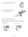
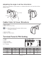
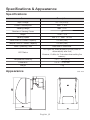
User Manual Passive-Infrared Sensor SIP-1212W Important Safety Instructions 1. Read these instructions. 2. Keep these instructions. 3. Heed all warnings. 4. Follow all instructions. 5. Do not use this apparatus near water. 6. Clean only with dry cloth. 7. Do not block any ventilation openings, Install in accordance with the manufacturer’s instructions. 8. Do not install near any heat sources such as radiators, heat reaisters, stoves, or other apparatus (including amplifiers) that produce heat. 9. Do not defeat the safety purpose of the polarized or grounding-type plug, A polarized plug has two blades with one wider than the other. A grounding type plug has two blades and a third grounding prong. The wide blade or the third prong are provided for your safety, If the provided plug does not fit into your outlet, consult an electrician for replacement of the obsolete outlet. 10. Protect the power cord from being walked on or pinched particularly at plugs, convenience receptacles, and the point where they exit from the apparatus. 11. Only use attachments/ accessories specified by the manufacturer. English _1 12. Use only with the cart, stand, tripod, bracket, or table specified by the manufacturer, or sold with the apparatus. When a cart is used. Use caution when moving the cart/apparatus combination to avoid injury from tip-over. 13. Unplug this apparatus during lighting storms or when unused for long periods of time. 14. Refer all servicing to qualified service personnel. Servicing is required when the apparatus has been damaged in any way, such as powersupply cord or plug is damaged, liquid has been spilled or objects have fallen into the apparatus, the apparatus has been exposed to rain or moisture, does not operate normally, or has been dropped. WARNING TO REDUCE THE RISK OF FIRE OR ELECTRIC SHOCK, DO NOT EXPOSE THIS PROCUCT TO RAIN OR MOISTURE. DO NOT INSERT ANY METALLIC OBJECT THROUGH THE VENTILATION GRILLS OR OTHER OPENNINGS ON THE EQUIPMENT. Apparatus shall not be exposed to dripping or splashing and that no objects filled with liquids, such as vases, shall be placed on the apparatus CAUTION CAUTION RISK OF ELECTRIC SHOCK. DO NOT OPEN CAUTION : TO REDUCE THE RISK OF ELECTRIC SHOCK. DO NOT REMOVE COVER (OR BACK). NO USER SERVICEABLE PARTS INSIDE. REFER SERVICING TO QUALIFIED SERVICE PERSONNEL. English _2 EXPLANATION OF GRAPHICAL SYMBOLS The lightning flash with arrowhead symbol, within an equilateral triangle, is intended to alert the user to the presence of “dangerous voltage” within the product’s enclosure that may be of sufficient magnitude to constitute a risk of electric shock to persons. The exclamation point within an equilateral triangle is intended to alert the user to the presence of important operating and maintenance (servicing) instructions in the literature accompanying the product. Class construction An apparatus with CLASS construction shall be connected to a MAINS socket outlet with a protective earthing connection. Battery Batteries(battery pack or batteries installed) shall not be exposed to excessive heat such as sunshine, fire or the like. Disconnection Device Disconnect the main plug from the apparatus, if it’s defected. And please call a repair man in your location. When used outside of the U.S., it may be used HAR code with fittings of an approved agency is employed. CAUTION These servicing instructions are for use by qualified service personnel only. To reduce the risk of electric shock do not perform any servicing other than that contained in the operating instructions unless you are qualified to do so. English _3 Please read the following recommend safety precautions carefully. y Do not Place this apparatus on an uneven surface. y Do not install on a surface where it is exposed to direct sunlight, near heating equipment or heavy cold area. y Do not place this apparatus near. y Do not attempt to service this apparatus yourself. y Do not place a glass of water on the product. y Do not install near any magnetic sources. y Do not block any ventilation openings. y Do not place heavy items on the product. User’s Manual is a guidance book how to use the products The meaning of the using sign in the book is following y Reference: in case of providing information for helping of product’s usages y Notice: If there’s any possibility to occur any damages for the goods and human caused by not following the instruction Ú Please read this manual for the safety before using of goods and keep it in the safe place. English _4 IR Sensor at a Glance Terminal Alarm LED Relay PIN BU3 PIN BU1 PIN BU4 Tamper Switch PIN BU2 White Light Filter What’s Included Screw (x2) 3X10 Flat Head Screw x2 (for fixing the bracket) User Manual/ Warranty Card Bracket Installation To open the cover and to assemble the bracket 1. Turn the screw on the bottom of the sensor anti-clockwise. English _5 2. Pull up the lower side of the product in the arrow direction to remove the cover. 3. Use 3mm flat head screws to fix the unit to the bracket. Then, make adjustment as necessary. 3X10 Flat Head Screw x2 (for fixing the bracket) Ceiling mount & wall mount The bracket is designed for both ceiling and wall mount installations, the bracket can be easily switched from one to the other according to the site requirements. 1. Ceiling Mount 2. Wall Mount English _6 Adjusting the angle in all four directions Adjust the orientation of the sensor in a desired direction, and use the bottom screw to fix it. Left/Right Up/Down Cable Color & Cover Structure • Black: GND • Red: VCC (12V±15%) J Check the polarity of the power cable to ensure the proper connection. • Green: COM • Blue: OUT (N.C/N.O) Terminal Panel & PIN Setting 1. GND 2. VCC 3. Alarm (COM) 4. Alarm (N.C/N.O) 5, 6. Tamper Alarm Tamper Memory Count Jumper Pin BU1 BU2 BU3 BU4 Use Count OUT LED Memory Upper 4C N.O ON ON Lower 2C N.C OFF OFF English _7 Specifications & Appearance Specifications Item Description Input Voltage DC 12V(±15%) Current Consumption Max. 17 mA Sensing Range Max. 12 m Number of Sensing Zones 9 Height 1.8 m ~ 3 m Sensing Speed Min. 0.2 ~ Max. 1.5 m/s Alarm Point of Contact Capacity 100 mA (28V) Tamper Point of Contact Capacity 100 mA (28V) Alarm Operating Time Less than 2.5 seconds LED Status LED lights up when an alarm occurs (turns off automatically after that) However, it blinks for 3 minutes when setting the memory. Temperature/Humidity -10˚C ~ 50˚C(95%) Dimension 103 X 71 X 53 mm Weight 110g Appearance Unit: mm English _8 Correct Disposal of This Product (Waste Electrical & Electronic Equipment) (Applicable in the European Union and other European countries with separate collection systems) This marking on the product, accessories or literature indicates that the product and its electronic accessories (e.g. charger, headset, USB cable) should not be disposed of with other household waste at the end of their working life. To prevent possible harm to the environment or human health from uncontrolled waste disposal, please separate these items from other types of waste and recycle them responsibly to promote the sustainable reuse of material resources. Household users should contact either the retailer where they purchased this product, or their local government office, for details of where and how they can take these items for environmentally safe recycling. Business users should contact their supplier and check the terms and conditions of the purchase contract. This product and its electronic accessories should not be mixed with other commercial wastes for disposal. P/No. : Z6806120201A-00