1
]Sears]
owners
manual
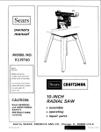
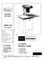
MODEL NO.
113.23301
Serial
Number
....
Model and serial
number may be found
at the left-hand side
of the base.
You should record both
model and serial number
[RRFTSMRNo
in a safe place for
future use.
12 INCH
RADIAL
CAUTION:
Read GENERAL
and ADDITIONAL
SAFETY-
• assembly
b:
INSTRUCTIONS
• operating
carefully
• repair
Sold by SEARS,
Part No. 63568
SAW
ROEBUCK
AND
parts
CO.,
Chicago,
IL. 60684
U.S.A.
Printed
ill U.S.A.
FULL
ONE YEAR
If within
one year from
workmanship,
Sears will
Warranty
service
United States.
This warranty
• state.
WARRANTY
ON CRAFTSMAN
the date of purchase, this
repair it, free of charge.
is available
gives you
by simply
specific
Craftsman
contacting
legal
rights, and
the nearest
you
safety
3. KEEP GUARDS
Keep proper
and
in
proper
adjustment
and
5. KEEP WORK AREA
and
be slippery
before
blades,
CLEAN
irrvite
accidents.
Floor
7. KEEP CHILDREN
8. MAKE
9. DON'T
be
a safe distance
from
switches,
10. USE RIGHT
by
20.
better
to do a iob
it was not
12. USE SAFETY
long
GOGGLES
such
as
position
before
plugging
The
STAND
ACCESSORIES
manual
for
recommended
instructions
that accompany
use of
improper
store
materials
is tipped
above or near the tool
to stand on the toot
DAMAGED
further
may
ON TOOL
Do not
CHECK
accessories
or if the
such that
to reach them.
PARTS
use of the tool,
a guard
or other
part that
is damaged should be carefully
checked to ensure that it
will operate properly
and perform
its ntended
function.
for
alignment
of moving
parts,
binding
of mowng
parts,
breakage
conditions
that
of parts,
mounting,
and any
other
may .affect
its operation.
A guard or
other
is damaged
part
that
should
be properly
repaired
or replaced
Do not wear loose clothing,
gloves, neckties or jewelry
(rings,
wrist
watches)
to get caught
in moving parts.
Nonslip
footwear
is recommended.
Wear protective
contain
safest
and
STARTING
is in "OFF"
injury could occur if the tool
tool is accidentally
contacted.
Check
or attachment
best and
lubricating
accessories
Serious
cutting
Before
and safer at the rate for which
11. WEAR PROPER APPAREL
hair covering
to
above the el bow.
19. NEVER
removing
TOOL
Don't force tool
designed for
the accessories.
cause hazards.
work
FORCE TOOL
It will do the job
it was designed•
ACCIDENTAL
sure switch
it is necessary
or
for
changing
Consult
the
owner's
accessories.
Follow
the
KID-PROOF
master
for
TOOLS
servicing;
when
bits, cutters, etc.
18. USE RECOMMENDED
ENVIRONMENT
kept
at all times.
in.
AWAY
WORKSHOP
with
padlocks,
starter keys,
Make
due to wax or sawdust,
Don't
use power
tools
in damp or wet locations
or
expose
them
to rain,
Keep work
area well lighted.
Provide adequate surrounding
work space.
and balance
TOOLS WITH CARE
16. DISCONNECT
17, AVOID
DANGEROUS
should
state to
tools
Keep
tools
sharp
and clean
performarrce.
Follow
instructions
changing accessories.
KEYS
benches
footing
15. MAINTAIN
Form habit of checking
to see that keys and adjusting
wrenches
are removed
from tool before turning
it on.
Al! visitors
area.
vary from
the
Use clamps or a vise to hold work when practical.
It's
safer than using your hand, frees both hands to operate
tool.
IN PLACE
order,
4. REMOVE ADJUSTING
AND WRENCHES
must not
which
throughout
or
14. DON'T OVERREACH
This tool
is equipped
with
an approved
3-conductor
cord and a 3prong
grounding
type plug to fit the
proper grounding
type receptacle.
The green conductor
in the cord is the grounding
wire. Never connect the
green wire to a live terminal,
6. AVOID
rights
Center
in material
13. SECURE WORK
ALL TOOLS
areas
Sears store or Service
for power
Read
the
owner's
manual
carefully,
Learn
its
application
and limitations
as well as the specific
potential
hazards peculiar to this tool.
Cluttered
Saw fails due to a defect
may also have other
instructions
1. KNOW YOUR POWER TOOL
in working
alignment.
SAWS
SEARS, ROEBUCK AND CO.
BSC 41-3
SEARS TOWER
CHICAGO, IL 60684
general
2. GROUND
Radial
RADIAL
hair.
Roll
long sleeves
(Head Protection)
Wear Safety goggles (must comply
with ANS Z87.1) at
all times.
Also,
use face or dust mask if cutting
operation
is dusty, and ear protectors
(plugs or muffs)
during extended
periods of operation.
21. DIRECTION
Feed work
of rotation
OF FEED
into a blade or cutter against
of the blade or cutter only.
22. NEVER LEAVE
UNATTENDED
Turn power off.
complete
stop.
TOOL
Don't
the direction
RUNNING
leave
tool
until
it cornes
to a
additional
safety
instructions
CAUTION:
Always
disconnect
the power cord before
removing the guard, changing the cutting tool, changing the
set-up
or making
adjustments.
Shut
off motor
before
performing layout work on the saw table.
WARNING:
DO NOT CONNECT
POWER CORD
THE
FOLLOWING
STEPS
HAVE
SATISFACTORILY
COMPLETED:
I.
II.
Assembly
and
Examination
alignment.
and
operating
switch,
elevation
control,
index
and
lock,
carriage
spreader
and antikickbaek
lock.
III.
UNTIL
BEEN
familiarity
with
ON-OFF
yoke index
and lock, bevel
lock,
guard
clamp
screw,
device,
and miter index and
Review and understanding
of all Safety
Operathrg
Procedures thru-out
manual.
Instructions
and
INSTALLATION
1.
Bet carnage
2.
Bolt the saw to the floor if it tends
slide during normal operation.
3.
Mount
-
lock
before
moving
the saw.
to
slip,
walk,
or
the saw so the table
is approximatety
39"
above the floor;
-- slopes slightly
downward
to the rear so the carriage
wil! not roll forward
due to gravity.
MINIMIZE
Most
setup
ACCIDENT
POTENTIAL
accidents
are caused
by
and operating
instructions:
FAILURE
TO
FOLLOW
(A) GENERAL
--Avoid
could
awkward
hand positions,
where a sudden stip
cause a hand to move into a sawblade or other
cutting
tool.
Never reach in back of or around the
cutting
tool
with
either
hand to hold
down the
workpiece,
or for any other reason; DO NOT place
fingers or hands in the path of the sawblade.
- Neve_ saw, dado, mold,
or rabbet unless the
guard is installed and set up as instructed.
proper
-NOTE
THE
FOLLOWING
DANGER
LABELS
WHICH
APPEAR
ON THE FRONT
OF THE YOKE
AND GUARD:
DANGER
AVOID
TO
INJURY
NOT
DO
FEED
MATERIAL
INTO
CU]TING
TOOL
--Always
maintain
control
of
NOT "let go" the workpiece
has come to a stop.
-If
-
for radial
-WARNING:
(GAINED
SAW)
TO
REMEMBER
A SECOND
INJURY.
saws
DO
NOT
ALLOW
FAMILIARITY
FROM
FREQUENT
USE
OF YOUR
BECOME
COMMONPLACE.
ALWAYS
THAT
A CARELESS
FRACTION
OF
IS SUFFICIENT
TO INFLICT
SEVERE
Before
starting
work,
verify
that no play exists
between
the column
& column
support,
or in the
carriage, and that arm, yoke, and bevel locks/clamps
are tight.
= A large proportion
of saw accidents is caused by use
of the wrong type blade, dull, badly set, improperly
sharpened
cutting
tools, by gum or resin adhering to
cutting
tools, and by sawblade misalignment
with the
fence.
Such conditions
can cause the material
to
stick,
jam
(stall
the saw) or "KICKBACK".
A
"KICKBACK"
occurs
when a part or all of the
workpiece
is thrown
back violently
toward
the
operator.
NEVER
ATTEMPT
TO
FREE
A
STALLED
SAW
BLADE
WITHOUT
FIRST
TURNING
THE
SAW "OFF".
If the sawblade
is
stalled
or
jammed,
shut
saw
"OFF",
remove
workpiece,
and check sawbtade squareness
to table
surface and to the fence, and check for heel. Adjust
as indicated.
--CAUTION:
DO NOT cycle the motor switch
"ON"
and "OFF"
rapidly, as this might cause the sawblade
to loosen. In the event this should ever occur, allow
the saw blade to come to a complete
stop and
re-tighten
the arbor nut normally,
not excessively.
--Do
not leave a long board
(or other
workpieee)
unsupported
so the spring of the board causes it to
shift on the table.
Provide
proper
support
for the
workpiece,
based
on its size
and the type
of
operation
to be performed.
Hold the work firmly
against the fence and down against the table surface.
-Never
use a
length
stop
on
the
free
end
of
the
workpiece
when crosscutting,
Never hang onto or
touch
the free end of workpiece
when crosscutting,
or a free piece that is cut off when ripping
while
power
is "ON"
and/or
the saw blade is rotating.
In
short, the cut off piece in any "thru-sawing"
(cutting
completely
thru the workpiece)
operation
must never
be confined
- it must be allowed
to move laterally.
Make sure your fingers do not contact
the terminals
when installing
or removing
the plug to or from a live
power source.
Never climb
on the saw, or climb
near the saw when
power
in "ON".
Never leave the saw with
power
"ON",
or before
the cutting
tool
has come to a
complete
stop. Lock the rnotor
switch and put away
the key when leaving the saw.
FROMJ
the workp_ece
- DO
until the cutting
tool
any part of this radial saw is missing or should
break,
bend or fall in any way, or any electrical
component
fail to perform
properly,
shut off power
switch,
remove cord from power supply and replace
damaged,
missing and/or failed parts before resuming
operation.
IF YOUR
SAW MAKES AN UNFAMILIAR
NOISE
OR
IF
IT
VIBRATES
EXCESSIVELY
CEASE
OPERATING
IMMEDIATELY
UNTIL
THE
SOURCE
HAS
BEEN
LOCATED
AND
THE
PROBLEM
CORRECTED.
-Do
not use any blade or other cutting
tool marked
for an operating
speed lower than 3450 RPM. Never
use a cutting
toot
larger
in diameter
than
the
diameter
for
which
the saw was designed.
For
greatest safety and efficiency
when ripping,
use the
maximum
diameter
blade
for which
the saw is
designed, since under
nearest the blade.
these conditions
the spreader
is
- Never turn your saw "ON"
before clearing the table
or work surface of all objects (tools, scraps of wood,
etc.}
except
the workpiece
and related
feed or
support
devices for the operation
planned.
-Never
perform
any operation
"FREE
HAND".
This
term means feeding the sawblade into the workpiece
(crosscutting)
or
feeding
the sawblade
or other
cutting
tool
(ripping)
without
using the fence to
additional
safety
instructions
for radial
support
_)_ guide the workpJece,
to prevent
rotating
or twisting
of the workpieee
during
the operation.
Never "RIP'"
in the crosscut position.
Never make a
miter cut with the arm in the 90 ° crosscut position.
- Never lower a revolving
cutting tool into the table or
a workpiece
without
first locking
the Carriage Lock
Knob. Release the knob only after grasping the Yoke
Handle.
Otherwise
the cutting
tool
may grab the
workpiece
and be propelled
toward you.
-The
sawblade,
dado, or other cutting
tool must be
removed
from
the
saw arbor
before
using the
accessory shaft (rear end of the saw motor).
NEVER
operate the
accessories)
saw with cutting tools (including
sanding
installed
on both ends of the saw arbor.
(B) RIPPING
1.
Feed force when ripping
must always be applied
BETWEEN
THE SAW BLADE
AND THE FENCE.
. . use a "PUSH
STICK"
for narrow
or short work.
2.
Whenever
possible,
use the in-rip
position
this
provides
minimum
obstruction
for feeding by hand
or push
stick as appropriate.
3.
Do nut release the workpiece
before operation
is
complete
- push the workpiece
all the way past the
rear (outfeed
or exit) of the sawblade.
4,
Make swe by trial before starting
the cut that the
antikickback
pawls will stop a kickback
once it has
started,
Points of pawls must be SHARP,
Reptace
when potnts are dull or rounded.
5.
Use a
inches)
push stick
when
ripping
or narrow (under 6 inches
6.
CAUTION:
antikickback
7.
A "KICKBACK"
occurs
during
a rip-type
operation.
It can occur when the workpiece
closes
in on the rear (outfeed
side) of the sawblade
(pinching),
binds
between
the
fence
and the
sawblade. (heel), or is grabbed by the sawblade teeth
(wrong-way
feed) at the uutfeed side. "PINCHING"
Never
reposition
with power "'ON".
the
Guard
or
9.
Position
the nose of the guard
workpiece,
and position!adjust
and spreader devices as instructed.
NEVER
stacking
10. NEVER
piece
piece
cut
more
workpieces
than one
vertically.
feed a workpiece
tbru
piece
at
a time
(butting
second piece against trailing edge of
being cut), even if of the same thickness.
Feed
each workpiece
individually
thru the sawblade, and
completely
beyond the sawblade, before ripping the
next wo_kpiece.
Use push stick if the rip cut is Jess
than 6" wide.
11. DO NOT pull
the workpiece
thru
12. Plastic
and
composition
(like
styrene
and
hardboard)
materials
may
be cut on your
saw.
However,
since these are usually
quite
hard arrd
firfished
not
side down
14. Position the saw so neither you, a helper,
observer
is forced
to
stand
in line
sawblade.
stop
{next
a
to
or a casual
with
the
15. Use extra care when ripping wood that has a twisted
grain or is twisted
or bowed - it may rock co the
table and/or
pinch the sawblade.
If bowed across
the width,
table.
place
concave
side
down
against
the
(C) CROSSCUTTING
ALWAYS
RETURN
THE
CARRIAGE
TO THE
FULL
REARWARD
POSITION
AT CONCLUSION
OF EACH CROSSCUT
TYPE OPERATION.
Never
remove your hand from the Yoke Handle unless the
carriage
is in this position.
Otherwise
the cutting
tool
may climb
up on the workpiece
and be
propelled
toward you.
2.
Place guard
antikickback
or workpiece,
3.
NEVER
gang crosscut
lining up more than one
workpiece
in front of the fence
stacked vertically,
or horizontally
outward
on the table
and then
in horizontal
position
and adjust
pawls to just clear the top of the fence
whichever
is higher.
pulling
saw thru:
the blade could pick up one or
more pieces and cause a binding or loss of control
and possible injury.
4.
Do not position
the Arm so the operation
you are
performing
permits
the cutting
tool
to extend
beyond the edges of the Table.
ES
1.
Use only
recommended
accessories
accessory section of this manual.
2.
Never operate this saw when equipped
with a dado
head or molding
head unless the molding
head
guard
is installed
see listing
of recommended
accessories.
The only exception
is when "top side"
dadoing
or molding,
when the sawblade guard must
be used. See detailed
instructions
that accompany
the dado head, molding
head, and molding
head
guard.
3.
The use of abrasive
or cut-off
wheels,
or wire
wheels, can be dangerous
and is not recommended.
the sawblade
position
your body at the nose fin feed) side of
the guard: start and complete
the cut from that
same side. This wilt require added table support
for long pieces.
the
may
the DANGER
warning
on the guard is aborted.
Do
not stand, or permit
anyone
else to stand, in line
with the path of a workpiece
that may be thrown
from the saw in this manner.
by
another
rip with
pawls
13. When sawing 1/4" or thinner
materials,
follow
all
normal
ripping procedures
except set sawblade into
table
top at least 1/8".
]-his will
minimize
the
tendency
for the sawblade to climb upon top of the
workpiece,
and possibly
cause an accident. DO NOT
let go of or stop feeding the workpiece
between the
blade and fence until you have pushed it completely
past
the
antikTckback
pawls.
Otherwise
the
workpiece
could get into the back of the sawblade
and be thrown
violently
[rom
the saw in the
direction
opposite
to the feed direction.
This is the
same action that would occur if the instructions
of
(D) ACCESSORI
the saw with
antikickback
the table) and be especially
attentive
to following
proper set-up and cutting
procedures.
Do not stand,
or permit
anyone
else to stand,
in line with
a
potential
kickback.
1.
to just clear the
the antikickback
the
Therefore,
short (under
12
wide) wot kpieces.
is genera!ly
avoided
by utilization
of the spreader,
and a sharp sawblade of the corrective
type for the
workpieee
being cut. "HEEL"
carl be avoided by
maintaining
the sawblade
exactly
parallel to the
fence. (see "DANGER"
warning on guard)
it can
be avoided
by maintaining
parallelism
of sawblade
to fence, feeding into the sawblade from the nose of
the guard only, and by utilizing
the spreader.
8.
slippery,
kickback.
saws
(Abrasive
different
glass.)
or cut-off
materials
as listed
in
wheels are used to saw many
including
metals,
stone,
and
ADDITIONAL
WEAR
SAFETY
INSTRUCTIONS
FOR RADIAL
SAWS
YOUR
The
operation
of
any
power
tool
can
result
in
foreign
objects
being thrown
into the eyes, which
can result in
severe eye damage. Always
wear safety goggles complying
with ANSI Z87.1 (shown on Package) before commencing
power tool operation.
Safety Goggles are available at Sears
retail
or catalog
stores.
CONTENTS
Page
15
18
21
25-26
28
Operating Controls
............................
Basic Saw Operations ...........................
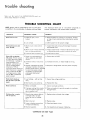
Trouble Shooting ..............................
Motor Trouble Shooting
Chart
................
Repair Parts ..................................
Guarantee and General Safety Instructions
Additional
Safety Instructions
to Operator
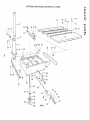
Unpacking
and Pre-Assembly
Instructions
Assembly
and Adjustments
.......................
Electrical
Connections
..........................
Page
2
3
5
6
13
...........
...........
............
F-'
TOOLS NEEDED
3/8-inch
wrench
7/16-inch
wrench
1!2-inch
wrench
9/16-inch
wrench
I::
_._
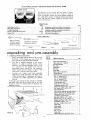
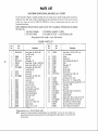
unpacking
Unpacking
_
Figure
Framing
f
Pliers
square
_: ,:
i "
!
and pre-assembly
and Checking
Contents
a.
Before proceeding
with the assembly of your
Craftsman
12-Inch
Radial saw, you should
these instructions
and follow them carefully.
b.
This
Saw is shipped
complete
in one carton.
However,
in order
to prevent
damage
during
shipment
and facilitate
packaging,
certain
items
are
removed
at
the
factory
and
must
be
reassembled
when
received
by
the purchaser.
These
"loose"
parts are shown
in figure 2 and
listed in the "Table of Loose Parts" below.
c,
Separate
all
"loose"
parts
from
packaging
materials
and check each item with figure 2 and
"Table
of Loose Parts", making sure all items are
accounted
for
before
discarding
any
packing
material.
If any parts are missing, Do
the Radial Saw, plug in the
switch
on until
the missing
installed correctly.
4
new
read
Not attempt
to assemble
power cord, or turn the
parts are obtained
and
5
2
8
Figure 2
li
S rewOrlver
(smo,,)
Pencil
1.
/:_
Key No.
(Fig. 2)
I
2
3
4
5
6
7
8
9
10
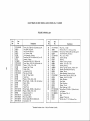
Table Of Loose Parts
Qty.
Table support (left-hand) .................
1
Tablesupport No. 2 (center) ...............
1
Basicsawassembly......................
1
Reartable .............................
1
Tablespacer ...........................
1
Rip fence .............................
1
Front table ............................
1
Table support(right-hand) ................
1
"Owners Manual" . ......................
1
LooseParts Carton (containingthe following items):
Hex-"L" wrench (1/8") .........
•........
1
Hex-"L" wrench (3/16") ................
1
Hex-"L" wrench(1/4") .................
1
Elevationcrankassembly................
1
Knobassembly,pull ....................
1
Screw,hex.-hd., 3/8-16 x 1" . ............
4
Lockwasher, medium,3/8" . .............
4
Washer,flat (steel), 13/32 x 7/8 x 1/16" ....
4
Nut, Square, 3/8-16 x 5/8 x 1/4". .........
4
Rip-scaleindicator .....................
2
Twin nut (for attaching rip scaleindicator) ..
2
Machinescrew,hex-hd.,5/16-18 x 3/4" ....
1
Washer,steel(flat), 11/32 x 7/8 x 1/16" ....
1
Lockwasher, medium5/16"'. .............
1
Nut, bex., 5/16-18 x 1/2 x 17/64". ........
1
Machinescrew,pan.-hd.,1/4-20 x 1". ......
7
Washer.steel(flat), 17/64 x 5/8 x 1/32" ....
7
Lockwasher,medium,1/4" . .............
6
Nut, hex., 1/4-20 x 7/16 x 3/16". .........
6
Tableclamp ..........................
3
Shaft wrench .........................
1
Arbor wrench.........................
1
Switch key ...........................
2
Nut, "'U'"clip .........................
1
Hook,cord...........................
!
Machinescrew, pan.-hd.,6-32 x 7/16". .....
4
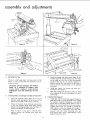
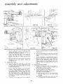
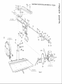
assembly and adjustments
BLOCK
Figure
4
LEFT-HAND
TABLE SUPPORT
SCREW
3/8-16
CARRIAGE
STOP
SCREW
14EX-L WRENCH
0/4
_ .)
rNCH)
LOCKWASHER
FLAT WASHER
(13/32
IN.)
(3/8 In .)
Figure
2..
Mounting
Mount
5
I [
Your Saw
on a CrafLsman
power
bench, in such a position
be free to rotate.
that
tool
crank
Installing
Motor
and
Carriage Assembly
TABLE
the
elevation
crank
Install
and
Iockwasher.
f.
Move the carriage back and forth along the radial
arm. It should roll smoothly
throughout
the entire
travel range.
clockwise
5 and, with
the
carriage
a
tighten
the cariage
(See figure 5.)
stop
screw
and
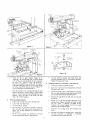
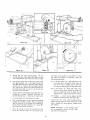
on Radial Arm
a.
Table Supports
Install right- and left-hand table supports
(figure 6)
with two 3/8-16 x 1-inch, hex-head screws, 13/32
flat
washers,
3/8-inch
Iockwashers
and 3/8-16
square nuts in each table support.
Refer to inset in
figure 6 for correct
location
of nuts and washers.
several turns
the shipping
block
(fibre
pad), located
the carriage and radial arm. (See figure 3.)
and discard the shipping block.
Refer
to figure
wrench,
remove
Iockwasher.
6
e,
Installing
Rotate
Figure
Grasp the carriage with both hands (figure 4) and
carefully
start the carriage bearings onto the tracks
on the radial arm, Be sure to hold the assembly
parallel
to the arm as it is carefully
slipped
into
position
until all four bearings are on the tracks in
order to prevent
excessive strain on the bearings
and tracks.
will
Install
the elevation
crank (figure
3} on end of
elevation
shaft and tighten
the set screw on flat
portion
of shaft with a 1/8-inch hex-L wrench.
to free
between
Remove
SUPPORf
d.
base, leg set, or flat
the elevation
WARNING: DO NOT CONNECT THE POWER
CORD TO A SOURCE OF POWER, THIS
CORD
MUST
REMAIN
UNPLUGGED
WHENEVER
YOU ARE WORKING ON THE
SAW.
3,
x I IN.)
Tighten
these screws just enough
to permit
the
table supports to slip when tapped with a mallet to facilitate
later
adjustments.
Tap each table
support
until
the screw
mounting
slots
are
positioned
with
screws
approximately
equal
distant from ends of slots.
1/4-inch
hex L
stop
screw
and
6
NO.2
SUPPORT
CARRIAGE
LOCK
KNOB
LATCH
PiN
HAPJ
BEVEL
LOCK
NUT
I
Figure
7
MrTER
Figure
bASE
8
SCALE
INDICATOR
CORD
SCREW (No.6
32×7/i6
R
H
CARRIAGE
I _1
\
IN DIC AT OR
"'A',
figure
7) with
one 5/16-18
x
hex-head
screw, 11/32-inch
flat washer,
Iockwasher
and hex nut. The nut should
the right, as shown. Tighten
in preceding
step a.
the
Slide the U-clip nut on forward
end of No. 2 table
support,
as shown in inset of figure 7. (The formed
portion
of the U-clip must be underneath
the table
support.)
Align
the hole in the U-clip nut with
hole in No. 2 table support,
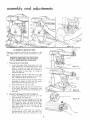
5.
Removing
Shipping
Spacers
a.
Tighten
the carriage
b.
Loosen
the bevel lock
knob.
(See figure
Lift
Tilt the motor
to the left, as shown
in figure 8.
The latch pin will drop into a notch when the
motor
and carriage
assembly
are rotated
to the
45 ° position.
screws
and
and shipping
two
5/16-inch,
spacers,
(See figure
hex-head
8.)
Remaining
a.
Install
swivel
b.
Screw
the cord
the power
"Loose
latch
cord
pin handle
hook
into
Parts":
into
(See figure 9)
(knob).
threaded
bole and hook
it.
c.
Attach
the power cord to radial arm by loosening
the cord clip attaching
screw, placing cord under
the clip and tightening
the attaching
screw.
d.
Remove the
lock knob.
e.
Attach
one of the two rip-scale
indicators
to the
carriage
cover (figure
10) with one twin nut and
two
No.
6-32
x 7/16-inch,
pan-head
screws.
Tighten
the screws
lightly
as the
rip scale
indicators
will be adjusted later.
f.
Re-install
knob.
g.
Remove
the left-hand
carriage
cover, attach the
rip-scale
indicator
as described
in preceding
instructions
and re-install
the cover.
pin handle.
discard
Lift the latch pin handle
and rotate
motor
and
carriage
assembly
back to a horizontal
position.
Tighten the bevel lock knob.
Installing
knob.
d.
Remove
f.
8.)
c.
e.
the latch
lock
I0
9
Install
the No. 2 table
support
(figure
7) by
"hooking"
the forward
end over the upper flange
of front base rail and attaching
the rear of support
be facing toward
screw as described
RIPSCAL_
@_"_
Figure
(at point
3/4-inch,
5/16-inch
HD.)
'_
' dOVER
Figure
IN.PAN
A
CLIP
right-hand
the
carriage
carriage
cover
cover
and
and carriage
carriage
lock
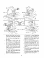
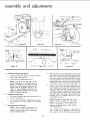
assembly and adiustments
Figure
11
ALIGNMENT
Alignment
instructions
most logical order to
Figure
13
INSTRUCTIONS
that follow
insure accurate
are presented
performance
in the
of your
saw.
WARNING:
MAKE SURE THE POWER CORD
IS NOT PLUGGED
INTO AN ELECTRICAL
OUTLET
WHEN WORKING
ON THE SAW.
Removing
a.
b.
Guard and Saw Blade
Loosen
the guard clamp
knob several turns and
rotate the guard to an upside-down
position.
(See
figure
11.) Loosen the knob still further,
until
indicator
groove or the clamp bar is exposed, to
allow
the guard to drop down
far enough
to
expose the shaft nut.
Place
the
arbor
wrench
on
the
shaft
nut
Hold the shaft wrench
dowr_ward
to loosen
and rotate
the shaft
Figure
14
Figure
15
Figure
16
and the
shaft wrench on the hex portion
of motor
just inside the saw blade. (See figure 12.)
c.
K_OB
shaft
the arbor wrench
nut. The motor
SAW
BASE
shaft
has left-hand
threads.
(See figure
d.
Remove
e.
Grasp the saw blade, slide it off the shaft and out
of the guard. {See figure
13.) Remove the inner
collar and guard. Place the guard and blade out of
work area.
Adjusting
a.
b.
the shaft nut and outer
12.)
Table Supports
Parallel
collar,
To Radial
Loosen
the bevel lock knob
and
latch pin handle. (See figure 14.)
Swivel the motor
counterclockwise
lift
Arm
up
until
on the
the saw
end of shaft is pointing
straight
down and the
latch pin handle "snaps"
into a detent.
(See figure
15.) Tighten
the bevel lock
knob. If the motor
shaft strikes some part of the saw base raise the
radial
arm enough
elevation
crank.
c.
to
clear
it
by
_L
rotating
the
Loosen
the
arm
latch
knob
by
rotating
it
counterclockwise
until
it stops. (See figure
16.)
This wilt free the radial arm, permitting
it to be
Figure
18
(LEFT
I
2
Figure
21
ABLE
MOUNT
until end of shaft is directly
over the rear position
of table support
No. 2. (See figure 18.) With the
attaching
screw hand tight,
tap the rear of No. 2
table support
upward
or downward
until the end
of motor shaft just touches the arbor wrench, held
between
the end of motor
shaft
and top of
support
as in the preceding step.
moved from right to left, by hand, Also, make sure
the carriage lock knob (figure 16) is loose enough
to permit
the carriage
to move freely
back and
forth on the arm.
Note:
In accordance
have been provided
the radial arm,
with the UL standard,
stops
to prevent
360 ° rotation
of
d.
The forward
end of the No. 2 (center)
table
support
is anchored
to the saw base with a slot
and,
consequently
is not adjustable.
For
this
reason,
this
location
is the starting
point
for
adjusting
all of the table supports.
(See figure 17.)
e.
Move
the
carriage
and
swing
the
radial
arm until
the end of motor shaft is positioned
directly
over
the U-clip,
located
on the outer
end of table
support
No. 2. Place the arbor wrench
near the
U-clip, then, with
the elevation
crank,
lower the
carriage until the end of the shaft just touches the
arbor wrench. (See figure 17.)
f.
Carefully
adjust the motor
up or down with the
elevation
crank until the arbor wrench (being used
as a "Feeler")
slides back and forth
with
only
slight resistance.
(See figure 17.)
NOTE:
Do not change the elevation
setting of the
motor until all table supports
have been adjusted.
g.
Remove
the arbor
wrench
and position
the motor
SUPPORT
[NG 5C
h.
i.
j.
k.
I.
Recheck the front
position
(figure
17), since a
change at the rear could slightly
affect the front
setting. Check back and forth until both front and
rear positions
are exactly the same height. Tighten
the attaching
screw and nut (figure 19).
Position
arm and carriage
against stop (approximately
50 ° miter) directly
over the center of left
hand table support.
Adjust the left hand support in
the same manner
as the No.
2 support
{See
Figure 20.)
Move
the motor
to the forward
end of the
left-hand
table support,
over the front
mounting
screw (figure 21), and adjust the forward
position
up or down as required.
Recheck
both rear and forward
positions
(figures
20 and 21) until the arbor wrench slides with the
same resistance at each position.
Several trials may
be required to produce an accurate setting.
Tighten
two
left-hand
table support
mounting
screws.
assembly and adjustments
ARM
LAICH
HANDLE
(K NOB)
_,_
F LAT
(1/4
,_/ASH ER
IN. )
TABLE
SLJPPORI
LATCH
"4 HANDLE
(1/4
WASHEiN.)
R.?'_
NUT
l I/4- 2O)
BEVEL
LOCK
KNOB
Figure
Figure
22
23
Figure
24
IFI[S HOLE NOT
USED
IN TABLE _NSTALLAItON
'€,'RE NC h
Figure
m.
n.
o.
b.
nuts on all screws
the U-clip nut.
Move the radial arm over to the right-hand
table
support
and adjust
it in the same manner,
as
described for the left-hand
support.
Loosen
the bevel lock knob,
lift the latch pin
handle,
and rotate
the motor
to a horizontal
position.
(See figure 22.) Tighten
the bevel lock
knob.
Move the radial arm to 0 ° position
and lock
tightening
the arm
latch
handle.
Tighten
carriage lock knob.
Installing
a.
Figure
25
Front
d.
In order
Table
Place the large front
table
board
on the table
supports,
locating
it so that eounterbored
holes in
the table match corresponding
holes in the table
supports.
(See figure 23.)
4.
Place a 1/4-inch
flat washer on each of the seven
1/4-20
x 1-inch,
pan-head
screws and insert
a
screw (and washer)
through
each of the seven
eounterboared
holes in the front
table (See figure
Install
six
1/4-inch
lock
washers
and
1/4-20
to facilitate
hex
10
threads
into
Squaring
a later
adjustment,
check
for
shift the front table on the supports
by
along edges with
a mallet.
(See figure
will
not slip,
loosen the screws just
permit
it to move slightly
when struck
mallet,
yet requiring
a firm
"tap"
to
The Crosscut
Travel
a.
Loosen the cariage lock knob, move the motor
approximately
center
of table
and tighten
carriage lock knob. (See figure 25.)
b.
Install
and tighten
to
the
the saw blade as follows:
NOTE:
Make sure the larger (flange)
each collar is next tb saw blade.
25)
and through
holes in table
supports.
One
screw, near the center of the table is threaded into
the U-clip nut mounted
on the forward
end of the
No, 2 support.
c.
the one that
Run all nuts up onto the screws firmly
but not
tight at this time. Tighten
the screw into the U-clip
lightly.
ability
to
tapping
it
24.) If it
enough
to
with
the
move it.
it by
the
except
27
face of
(1)
Place the
26) with
outward).
inner collar on motor shaft
flange
next
to saw blade
(figure
(facing
(2)
Install
the saw blade, outer collar and shaft
nut. Tighten
the nut as shown in figure 27.
2_RM [&ECH
klAN
tt_
LATCH
HANDLE
BEvEl
lOCK
_rdO_
Figure 28
Figure
30
MJTER
SCA[E
ZHNG
SCREWS
Figure
C.
Rotate
Figure
3 !
the
arm
latch
handle
counterclockwise.
(See figure
yoke clamp handle and bevel
d.
Pull
the
arm
latch
(knob)
1/4
turn
and
move radial
(1)
f.
Lower
Place a framing
square on the table with the short
leg against rear edge of table as shown in figure 30
and the long leg of the square just contacting
a
tooth of the saw blade. (Position
"A", figure 30.)
Mark this tooth with a soft pencil.
the blade until
it just
If
(2)
clears the table.
the
radial
arm,
carriage
the
is moved
saw tooth
back
"A"
and forth
should
just
front
of
edge of table (figure
rear
toward
right-hand
front
Recheck
holddown
table,
the
30) moves
into
blade
tap
from
the
31) with
the
the
front
of
the
left-hand
the mallet.
table,
edge of table with
two
miter
with
Adjustment
the
of
the
all table
32.)
scale
attaching
screws
miter
scale until
the 0 °
Tighten
screws
the indicator.
the
will
automatically
correct
positions
of the radial arm.
tap
the mallet.
... and, if correct,
tighten
screws securely. (See figure
33) and rotate
mark is aligned
and re-check.
11
the
does
make
If saw tooth
("A",
figure
30) moves away
from the square when moving the blade from
Loosen
touch
"A"
points,
figure
moving
front
(figure
on the
("A",
when
the
all
to
the
(3)
square
33
If saw tooth
at
rear
NOTE:
When
the saw tooth
the
Tighten
the arm latch handle (figure 28). (Refer to
paragraph
entitled
"Precision
Indexing"
for
detailed
instructions
on indexing
the radial arm.)
g.
at all positions.
not touch
the square
following
adjustments:
arm approximately
10 ° to the right. Release the
arm latch lever and move radial arm slowly toward
the left until it "indexes".
Do not bump or jar the
arm. Tap the arm latch lever solidly
with palm of
the hand (figure 29) in order to seat the arm lock
pin firmly
in the arm latch.
e.
Figure
the square
28.) Make sure the
lock knob are tight.
lever outward
32
crosscut
the
45 °
travel
index
assembly and adjustments
EV¢Iv_E[
L_TDH
YOKE
CLAMP
PIN
K_OB
HANDLE
CARRIAGE
LOCK
KNOB
TABLE
SPACER
"rOKE
Figure
35
Figure
C,\RRbXGE
LOCK
36
o o
rE_<
KNOB
I
REAR
FENCE
_O NEARESJ"
BLADE TOOTH
_
0
Figure
5.
Installing
37
Figure
Remaining
Table Boards
a.
Install the fence, rear table, table spacer and three
table clamps. (See figure 34.)
b.
Tighten
the three
table clamps firmly.
NOTE:
The
of
life
the
saw
table
can
6.
Setting
Bevel Index
when
be
35)
b.
If not, loosen
the indicator
screw.
attaching
screw, adjust
tighten
the attaching
Adjusting
the indicator
to 0 ° and
should
38
fABLE
i,
";ABLE
FRONT
TABLE SPACER
BOARD
Figure 39
Loosen
the carriage
lock
knob
(figure
36) and
move the motor until the edge of the blade, when
spun by hand, just touches
the front face of the
fence. (See figure 37.) The rip-scale
indicator
(on
the right hand side of radial arm) should now read
"0"-inches
on lower portion
of the "In-Rip"
scale.
(See figure 38.) If not, loosen screws and shift the
indicator
until
it is aligned
with
the "'0" mark,
then tighten the screws.
Scale
The bevel indicator
(figure
the bevel index scale.
REAR
between the motor and the fence. Lock the yoke by
tightening
the yoke clamp handle. (See figure 36.)
making
a.
.'
PENCE
FROM
With the fence in its normal
position
(next to the
front table), loosen the yoke clamp handle (figure
36), lift up on the swivel latch pin knob and rotate
the yoke as shown to index the yoke 90 ° from the
cross-cut
position.
This will locate the saw blade
greatly
lengthened
if a 1/4-inch
piece of
plywood
is tacked
to the table top after
leveling. Then all cutting
can be done in the
added
piece
of plywood
instead
of the
table.
It
also eliminates
the
need
for
changing
elevation
settings
right- or left-hand
miter cuts.
m/ X-..."
©
MEAS:JRE
read 0 ° on
NOTE:
Rip Scale Indicators
and fence
in the
position
shown
in figure
37, the
portion
of the "In-Rip"
scale is used.
fence
is re-located
at the extreme
With
the saw blade
lower
If the
rear
position,
the upper portion
scale would be used.
NOTE:
The
rip scales and pointers
are
intended
to be used for quick settings. For
greater
accuracy,
take direct
measurement
between blade and fence.
of the "In-Rip"
The "Out-Rip"
scale indicator
on the left-hand
side of radial arm is adjusted
in essentially
the
same manner as the "In-Rip"
indicator,
except the
12
fence
should
positioned
measured
be at
extreme
rear
as shown in figure
between
the fence
and
the
blade
to
[he sawblade
sawblade):
39. With 12 inches
(when
in full rear
With
the
saw blade
and fence
in the
position
shown
in figure
39, the upper
portion
of the "Out-Rip"
scale is used. If the
fence is moved to normal
position
(at the
rear of front table) the lower portion
of the
"Out-Rip"
scale is used.
d.
8.
the Guard
Remove
(1)
Move
the
mid-position
carriage lock
(2)
Elevate
elevation
(3)
Position
(4)
Remove shaft
inner collar.
carriage
on radial
knob.
the
saw
crank.
wrenches
slightly
rearward
arm and tighten
of
the
When not in the cut (Guards in full down position
(Touching
the table)
and carriage
in ful!
rear
position
behind fence):
(b)
When
performing
(sawblade 90 ° to table
90 ° crosscut
surface).
operations
protection
to
(a)
Axially
when in the cut, because the inner and
outer
blade guards ride on top of the fence or
workpiece
during the cutting operation;
(b)
Radially
(in a direction
teeth,
or perpendicular
sawblade).
in line with the
to
the
plane
cutting
of the
blade
30
as shown
nut,
outer
turns
in figure
collar,
of
of
the
the
40.
saw blade and
Hold the guard in upside-down
position
and slide
it into position
on the motor shaft, allowing
it to
hang by the slot
in the inner
(clear
plastic)
assembly. (See figure 41.)
c.
Slide the inner collar on the motor shaft (with the
flat side facing outward),
then place the saw blade
on the shaft. Make sure the teeth are pointed
for
proper saw rotation.
d.
Place
the.outer
collar
on the
shaft
with
the
side facing
the saw blade.
Start
the shaft
(left-hand
threads)
on the shaft and tighten
shaft nut securely. (See figure 42.)
Rotate
tighten
plane
the saw blade as follows:
b.
e.
the
The lower retractable
guard will not provide
the operator,
either crosscutting
or ripping:
Loosen
the yoke clamp
handle,
lift up on the
swivel latch pin knob and return the blade to the
90 ° position.
Installing
a.
to
(a)
position)
and face of saw blade, the rip-scale
indicator
should be positioned
to read 12 inches
on the upper portion
of the "Out-Rip"
scale.
NOTE:
(perpendicular
the
the
flat
nut
the
guard until
the knob is in front
and
knob to secure the guard in position.
This
lower
retractable
additional
protection
to
electrical
guard
is designed
to
provide
the operator
in an axia! direction
Figure
41
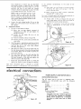
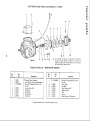
connections
POWER
SUPPLY
AND
MOTOR
DATA
MOTOR SPECl FICATIONS
The AC motor
capacitor
run,
specifications:
¢, R NC H -
used in this saw
non-reversible
type,
is a capacitor
start,
with
the following
Voltage
.......................
Amperes
......................
Hertz (cyc.)
.....................
Phase
.......................
RPM
........................
Rotation
(viewed from
saw blade end)
..........
Figure
240
7.0
60
Single
3450
Clockwise
CAUTION:
This saw is wired for
on 240 volts only. Connect to a
branch
circuit
protected
by a
time delay or circuit saver fuse
breaker,
42
13
operation
15*ampere
15-ampere
or circuit
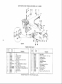
electrical
connections
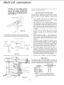
WARNING:
DO NOT PERMIT
FINGERS
TO
CONTACT
THE
TERMINALS
OF
POWER
OR
MOTOR
PLUGS
WHEN
INSTALLING
OR REMOVING
THE PLUG
TO OR FROM
A LIVE POWER SOURCE.
(SEE FIGURE
43.)
This tool should be grounded
operator
from electrical
shock.
MOTOR
/
IS AVAILABLE
If the protector
opens
the line and stops
motor,
press the saw switch
to the "'OFF"
immediately
and allow the nqotor to cool.
2.
After
to
a
safe
operating
temperature,
the
As soon
position,
normally
position.
TYPE
PLUG.
4.
Frequent
opening
of fuses or circuit
breakers
may
result if motor is overloaded,
or if the motor circuit
is
fused with other than those recommended.
Do not use
as the red button
will
snap into running
the
saw
may
be started
and operated
by pulling
out the saw switch to the "ON"
a fuse of greater
company.
5.
BLACK
cooling
the saw
position
3.
43
CAP - FLAG TERMINAL
_OWER
PROTECTION
1.
T B©X
FOR THIS
_he
over-load
protector
can be closed manually
by pushing
in the red button
on the motor capacitor
cover. If the
red button
will not snap into place immediately,
the
motor
is still too hot and must be allowed to cool for a
while longer.
(An audible click will indicate
protector
is closed.)
Figure
NO ADAPTER
in use to protect
The saw motor
is equipped
with
a manual-reset
thermal
overload
protector
(figure 45). designed to open the power
line circuit
when the motor
temperature
exceeds a safe
value.
GROUNDEL;
OU[LE
SAFETY
while
BLACK
capacity
Although
the motor
voltage and frequency
without
is designed
specified
consulting
the power
for operation
on the
on motor nameplate,
normal
loads will be handled
safely on voltages not
more than 10% above or below the nameplate
voltage.
Heavy loads, however,
require that voltage at motor
terminals
equals the voltage specified on nameplate.
CORDI
Z
w
_
WHITE
0
":GROUND
SCREW
_
6.
WHITE
CORD
SWITCH
Figure
Most
motor
troubles
may
be traced
to loose or
incorrect
connections,
overloading,
reduced
input
voltage (such as small size wires in the supply circuit)
or when the supply
circuit
is extremely
long. Always
check connections,
load and supply
motor
fails to perform
satisfactorily.
and lengths with the table in the next
44
7.
Replace
or repair
damaged
or worn
circuit
when the
Check wire sizes
paragraph.
cord
immediately.
WIRE SIZES
The following
table
lists
connecting
the motor to the
extension
cords which
have
and 3-pole receptacles
which
Length of the
Conductor
50 feet or
100 feet or
100 feet to
150feet
to
200 feet to
less
less
150 feet
200feet
400 feet
recommended
wire
sizes for
power source. Use only 3-wire
3-prong
grounding
type plugs
accept the tool's plug.
Wire Size Required
(American Wire Gauge Number)
240 Volt Lines
No.
No.
No.
No.
No.
14
12
10
8
6
NOTE:
For circuits
of greater length,
the
wire size must be increased
proportionately
in order to deliver ample voltage to the saw
motor.
Figure
45
14
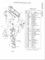
operating
controls
1
2
/
3
5
4
\
DEPIH
OF
CUT
OF
CUr
O
,_NGLE
_ARRIAS[
1
2.
3,
4
5.
6.
7.
8.
9.
t0,
1 1. Bevel
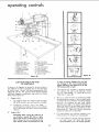
Arm Latch Lever
Swivel Lalch Pin Knob
Rip Scale Indicator
Radia_ Arm Indicator
Radial Arm Scale
Carriage Lock Knob
Yoke Clamp Handle
Switch
Key
Elevation
Crank
Bevel Index Indicator
Index
L()1:_
Scale
12. Bevel Lock Knob
13. Anti-Kickback
and Spreader
Assembly
14. Bevel Index Handle
15. Latch Pin Handle
16. On-Off Switch
17. Arm Latch Handle
18. Guard Clamp Assembly
19. Accessory Shaft
BLADE
ANI;LE
POWER WITCH
Figure
46
w
of
six diagrams
are located
on the
top
surface
of
the radial arm in order to designate the controls
that must
be used in basic "set-ups"
and operating
procedures.
(See
figures 46 and 47.) The operator
should become familiar
with these diagrams and operation
instructions
that follow
before operating
the saw.
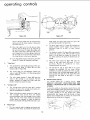
1.
"Depth
a.
Two controls
are involved
in releasing,
securing
and indexing
the angle of the radial arm. These
are: arm latch handle,
(17, figure 46) and arm
latch lever (1, figure 46).
The arm is unlocked
from
counterclockwise
rotation
of Cut"
The diagram shows the elevation crank (9, figure
46) which is used to raise and lower the saw blade.
Clockwise
rotation
raises
the
blade
"Angle
any position
by a slight
of the arm latch handle
(17, figure 46) and is locked in any desired
position
by
rotating
the arm
latch
clockwise
until tight.
The radial arm has
stops at 0 ° and 45 ° left and right, and is
from
these index positions
by unlocking
latch handle (17, figure 46) 1/4-turn
and
out the arm latch lever (1 figure 46).
...
counterclockwise
rotation
lowers it. One complete
turn of the handle will raise or lower the saw blade
1/8-inch.
2.
47
it stops, to prevent damaging the arm lock
pin. Damage
of this nature would prevent
proper indexing of the radial arm at 0 ° and
45 ° positions (left or right).
LOCATION AND FUNCTION
OF CONTROLS
A series
Figure
angular
handle
positive
released
the arm
pulling
of Cut"
C.
CAUTION:
When moving the radial arm in
any direction
beyond
45 ° (left or right),
always pull out the arm latch lever (1, figure
46), or loosen the lever by rotating the arm
latch handle (knob)
counterclockwise
until
For
most positive
and accurate
settings
at
index positions,
the following
is recommended:
(I)
15
the
If the radial arm is already indexed, rotate the
arm latch handle
(17, figure
46) I/4
turn
countercloskwise
from
the locked
position,
operating
controls
ZAB
A
TAB
LOWER
OUTER
LOWER
GUARD
TAB
S
NNER
GUARD
OUTSIDE
VIEW
ARtd_ LATCH
W'NG
SCREV_
C
iNS1 lie
VIEW
HANDLL
Figure
48
Figure
49
i
pull out the arm latch lever (1) and move the
radial arm off the index position.
Release the
arm latch lever (I).
(2)
Move
the
radial
arm
into
the desired
blade angle are: bevel lock knob (12,
and latch pin handle (15, figure 46.)
b.
index
position
(do not bump or jar it) and push on
the arm latch lever (1, figure 46) solidly with
the palm of the hand. (See figure 48). This is
very important
as it insures proper seating of
the arm lock pin in the arm latch, thus always
returning
the arm to the correct position.
(3)
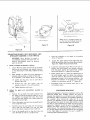
3.
"Yoke
a.
4.
5_
The swivel
latch
pin automatically
indexes the
yoke at each 90 ° position.
Lift the spring-loaded
knob to release it.
C.
The yoke clamp
handle (7, figure 46)
yoke
to the carriage
in any position.
handle
forward
to release the yoke;
handle rearward to secure the yoke.
"Carriage
locks
Pull
push
lower guards from
lower guards with
lowering
the saw
binding
(with power off},
lift
tabs (A or B, figure 49) while
blade to the table in a bevel
position.
8.
ON-OFF
Switch
and Key
The
On-Off
switch
has a locking
feature.
SHOULD
PREVENT
UNAUTHORIZED
POSSIBLY
HAZARDOUS
USE BY CHILDREN
OTHERS.
Lock"
The carriage
lock
knob (6, figure 46) is rotated
clockwise
to secure the carriage on the radial arm,
and counterclockwise
to release it.
b.
When performing
a square crosscut
or angle cut,
the
carriage
lock
knob
must
be rotated
counterclockwise
until the carriage is free to travel
along
the arm. This
knob
should
be tightened
except
when the operator
is ready to grasp the
bevel index handle (14, figure 46) and make a cut.
a.
The bevel lock
knob (12, figure
46) locks the
motor
to the yoke
when
the motor
is in any
position.
Rotate
it
clockwise
to
lock;
counterclockwise
to unlock.
The lift-tabs
(A and B, figure 49) on the guard
assembly
are provided
for
use under
certain
conditions.
In order to prevent
the inner or outer
the
the
the
a.
"Blade
engage.
d.
They are:
and yoke
b.
The bevel index scale (11, figure 46) indicates the
angular
position
of the motor
with
respect to
horizontal
from
0 ° to 90 ° in either
vertical
The latch pin handle (15, figure 46)automatically
indexes
the motor
at 0 °, 45 ° and 90 ° up and
down.
Lift the latch pin handle to release it. At
any other position,
the latch pin handle does not
Pivot"
are used in this operation.
pin knob
(2, figure 46)
(7, figure 46).
controls
used in angular
of the motor to provide
positioning
the desired
THIS
AND
AND
To turn the switch on, the operator
inserts the key and
hooks the forefinger
of the right hand under the end of
switch
lever and pulls forward.
The switch is turned off
by simply
pressing
in on the switch lever. When
removing
the key, always hold
the
against end of switch lever to prevent
being turned on as the key is removed.
thumb
or finger
the switch from
i
I
Angle"
The two
indexing
46)
position.
Lock the radial arm by rotating the arm latch
handle (17, figure 46) clockwise until tight.
Two controls
swivel
latch
clamp handle
figure
t!
and
saw
16
,
SPREADER
ANTI-KICKBAC
K
PAWL
i
_DIRBCTIO
N OF FEED
DIRECTION
OF
KICKBACK
22-ANTI-KICKBACK
POSITION
MINIMUM
(Make sure by trial before
cut that
the Anti-Kickback
C-U ARD CLEARANCE
stop a Kick-back
Figure
ADJUSTING
GUARD, ANTI-KICKBACK
AND
SPREADER ASSEMBLY,
FOR RIPPING
WARNING:
anti-kickback
1.
Check
and Adjust
pawls
the Spreader
by
grasping
Loosen the wing screw and with tab (C, figure 49)
position
the anti-kickback
and spreader assembly
to near the bottom
of the blade. Tighten
the wing
screw.
b.
Sight (visually)
to check for proper alignment
of
spreader with saw blade, as shown in figure 50.
If the spreader is not aligned, adjust it as follows:
(2)
(3)
Loosen
two
spreader
figure
Rotate
spreader
hex
nuts
with
fingers
until
is directly
in line with saw blade.
Tighten
Adjust the
follows:
a.
both
guard
hex
nuts,
one
on
each
side
the
in the
position
g.
Loosen the wing screw (figure 49) and with tab "C"
position
the anti-kickback
and spreader
assembly
until
the pawls assume the approximate
position
shown (See figure 52). Tighten
the wing screw.
h.
Before making the cut,
the anti-kickback
pawls
under the pawls in the
attempting
to slide it in
direction
of kickback.
readjust with wing screw
check the effectiveness
of
by sliding
the workpiece
direction
of feed and then
the reverse direction
- the
If the pawls do not catch,
and tab "'C" (figure 49).
i.
Periodically
maintain
check
anti-kickback
and
anti-kickback
assembly
as
and
sharp
tips
on the
pawls.
PRECISION
pull
out the on-off
c.
Carefully
lower the saw blade with the elevation
crank
until
the saw blade
cuts into
the table
of approximately
switch
1!32-inch.
in the on-off
switch
to stop the motor
the blade to come to a complete
stop.
INDEXING
Experienced
operators
of precision
equipment,
such as this
Craftsman
Radial
Saw,
normally
acquire
the habit
of
indexing
the machine
in one direction
only, whenever
a
new setting is made in preparation
for a different
operation.
For example:
when
moving
the
radial
arm to a new
position,
it is advisable to move it slightly
past the desired
index position,
then return it slowly and carefully
to latch
and lock it. Figure 48 shows the radial arm being securely
indexed by "tapping"
it with the palm of the hand. Swivel
indexing
and bevel indexing
can be accomplished
in a
similar manner. This indexing
technique
tends to neutralize
any stresses imposed upon saw components
and contributes
to the high degree of accuracy
the saw is capable
of
lock knob. Also, make
yoke clamp handle and
Plug in the power cord,
lever to start the motor.
Push
allow
be ripped
Loosen
the guard clamp
knob
(figure
50) and
rotate the guard so that it just clears the workpiece
(figure 51). Tighten the guard clamp knob.
of
b.
d.
to
hex nuts firmly.
cut. Tighten
the carriage
sure the arm latch handle,
bevel lock knob are tight.
to a depth
Place the workpiece
shown in figure 51.
f.
50).
Position
the saw blade the proper
distance from
the fence to produce
the desired width
of the rip
surface
once it has started)
as follows:
a.
(1)
the
will
Figure 52
e.
Never
position
the guard
or
assembly with power ON; nor
position
anti-kickback
pawls or spreader.
51
starting
Pawls
and
producing
17
when
operated
expertly.
basic saw operations
BASIC
SAW
OPERATIONS
REQUIREMENTS
(OPERATIONS
Yok_r Craftsma_
12inch
Radial
Saw is an extremely
versatile
tool, capable of performing
innumerable
cuts with
sufficient
accuracy to satisfy both amateur and professional
wood-working
requirements,
Basic
saw
operations
are
summarized
into six categories,
explained
and illustrated
in
the following
paragraphs.
A manual entitled
"The
Radial
Saw'"
is available
at your nearest Sears Retail
Store or
Catalog
Order
House. This manual
contains
considerable
data and project ideas applicable
to the radial saw.
NOTE:
Refer
"OPERATION"
descriptions
to
for
paragraphs
illustrations
under
and
FOR CROSSCUT
1 THROUGH 4)
1.
ArboP nut must be tight
in horizontal
position.
and saw blade
2.
Arm
must
3.
Adjust
the anti-kickback
assembly
clear the workpiece,
or fence.
4.
Work
must be held firmly
against table end fence. For
workpieces
thicker
than
the
fence
is high,
it
is
recommended
that
a higher
fence be cut (at least
workpiece
thickness)
and inserted
for that operation
being performed.
Always
place the fence in the most
forward
position
(farthest
from
the column
support)
compatible
with the workpiece
being processed and the
operation
being
performed.
With
the carriage
fully
retracted,
the blade should not contact the workpiece
when
placed
against
the fence,
within
the stated
capacities
of your saw.
5.
Blade should
6.
Hands must
be kept well away
7.
Yoke
handle
8.
Bevel index
9.
Blade should cut into
more than 1/32 inch.
of controls.
latch
handle
clamp
(knob)
so
the
pawls
just
set.
from
must be in locked
must
installed
be tight.
be sharp and correctly
knob
guard
saw blade.
position.
be tight.
the
table
or plywood
cover
not
10. Pull the saw forward
just
far enough
to sever the
lumber,
tt is dangerous
if the blade has been pulled too
far out beyond the piece being cut. When it is returned
it can pick up the right hand piece and throw it over the
fence°
11. For operations
No. 3 and No. 4, observe
additional
instructions
under
paragraph
"Operating
Controls"
"Blade Angle".
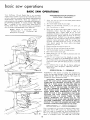
OPERATION
-
No. 1 - CROSSCUT
Crosscutting
is the process of sawing the workpiece
by
pulling
the saw blade through
it and using the fence as a
support
for the edge of the workpiece.
(See figures
53
through 56.) Never crosscut free-hand.
WARNING:
BEFORE
CROSSCUTTING,
MAKE
SURE
THE
ARM
LATCH,
BEVEL
LOCK
AND
YOKE
CLAMP
ARE ALL
SECURED.
NEVER
USE A LENGTH
STOP OR A FIXED
GUIDE
ON THE
FREE
END OR
EDGE
OF A WORKPIECE.
(SEE
INSTRUCTION
13
UNDER
"SAFETY
INSTRUCTIONS
TO OPERATOR".)
DO
NOT
CROSSCUT
WORKPIECES
THAT
PLACE
YOUR
HANDS
CLOSE
TO THE
PATH OF THE SAW
BLADE.
WHEN
MORE
EXPERIENCE
IS GAINED
BY
USING THE
PULLING
SAW,
THE
IT WILL
BE NOTICED,
THAT WHEN
SAW
TOWARD
YOU
DURING
CROSSCUTTING,
THE
BLADE
TENDS
TO
FEED
ITSELF
THROUGH
THE
WORK
DUE
TO THE
ROTATION
OF THE BLADE
AND THE DIRECTION
OF
BEVEL
THE
FEED.
THEREFORE,
THE OPERATOR
SHOULD
DEVELOP
THE HABIT
OF HOLDING
HIS RIGHT ARM
STRAIGHT
FROM THE SHOULDER
TO THE WRIST.
LOCK
OPERATION
No. 2 - MITER
CROSSCUT
Miter crosscutting
is the process of sawing a board at any
angle other than a 90 ° (square) cut. (See figure 54.) The
45 ° miter angle is a popular
one, since two boards cut to
45 ° can be assembled to form a 90 ° corner for producing
a
Figure
55
square
18
or rectangular
frame.
The
radial
arm
is set to
the
Provide a straight
edge, even if this means temporary
nailing
of an auxiliary
straight-edged
board
to the
work.
If the workpiece
is warped, turn the hollow side
down.
desired angle of cut; yoke and bevel settings indexed at 0 °
(and locked) as in square crosscutting.
The board being cut
is hetd firmly
against the fence and the carriage pulled
forward
along the radial arm to perform
the desired cut. As
in "Operation
No. 1", the carriage
should be r-eturned to
full rear position
and the saw blade allowed to come to a
comolete
stoo before removinQ the boards from saw t_ble.
OPERATION
No. 3 -
BEVEL CROSSCUT
Bevel crosscutting
is the process of sawing at g0 ° (square)
across the board with
the saw blade set at an angle other
than g0 ° to the saw table. (See figure 55.) The radial arm
and yoke are indexed at 0 ° and locked, but the bevel is set
to the desired angle of cut. The board is held firmly against
the fence and the carriage pulled forward
along the radial
arm to produce
the cut. The carriage should be returned
to
full rearward position
and the saw blade allowed co come to
a complete
stop before removing
the boards from saw table.
OPERATION
5.
6.
7.
Stand
a little
to one side of center
to avoid being
sprayed with sawdust and to be clear of work in case of
kickback.
When ripping short or narrow work, always use a push
WHEN RIPPING
(OPERATIONS
4.
4.
stick applied to the section of the workpiece
between
the blade and fence
... push the work past the blade
so it is clear of the blade. This procedure
will minimize
the possibility
of kickbacks.
In-Ripping
(See figure 57.) Time radial arm and bevel are
indexed at 0 ° and locked, but the yoke is twned 90-degrees
in a clockwise
direction
(viewed
from
above)
from
the
crosscut
position.
Thus, when standing
in front of the saw,
the
blade
would
be rotating
counterclockwise.
After
positioning
the guard
and anti-kickback
mechanism
the
workpiece
is fed from
the right-hand
side of the saw, as
shown in figure 57. The "in Rip" scale is on the right-hand
side of radial arm.
Compound
crosscutting
is the combination
of miter and
bevel crosscuts.
(See figure 56.) The radial arm arrd bevel
are set to produce the desired cut; the yoke is indexed at O°
and locked. The board is held firmly
against the fence and
the carriage pulled forward
along the radial arm to produce
the cut.
Again,
the carriage
should
be returned
to full
rearward
position
and the saw blade allowed to come to a
complete
stop before removing
boards from saw table.
1.
2.
3.
Always use the saw guard and make sure the spreader is
correctly
aligned with the saw kerf. Wood cut with the
grain tends to spring the kerf closed and bind the blade
and a kickback
could occur.
5.
No. 4 - COMPOUND
CROSSCUT
REQUIREMENTS
3.
5 AND
6)
Carriage lock knob must be tight.
Radial arm must be locked in 0 ° position.
Work must be held firmly against table and fence while
feeding through.
Guard and anti-kickback
mechanism
must be properly
set. Observe
instructions
in paragraph,
"Adjusting
Guard, and Anti-Kickback
and Spreader Assembly,
for
Ripping."
Blade should be sharp and correclty
set.
Hands must be kept well away from saw blade.
When
ripping
narrow
or short
stock,
always use a
push-board.
Saw blade must
be parallel
possibility
of kickbacks.
to
fence,
to
minimize
OPERATION
No. 5 -- OUT-RIPPING
AND IN-RIPPING
1.
Ripping
is the process of sawing the workpiece
by
feeding ;t into the saw blade when using the fence as a
guide and as a positioning
device to obtain the desired
width
of cut.
WARNING:
BEFORE
(See figures
NEVER
RIPPING,
G U A R D,
ANTI-KICKBACK
57 through
RIP
MAKE
SPREADER
PAWLS
5g.)
FREE-HAND.
SURE
THE
ARE
AND
SET UP
HANDL
_',K_Jo_)
PROPERLY.
ALSO,
MAKE
SURE
THE
SAW BLADE
IS PARALLEL
WITH
THE
FENCE.
NEVER
RIP
WORKPIECES
SHORTER
THAN
THE
SAW
BLADE
DIAMETER.
2.
OKE
Am_L,_rCH
HANDLE
BE/ELLOCK
_r,_o_
Since the work is pushed along the fence, it must have
a reasonably
straight
edge in order
to make sliding
contact with the fence. Also, the work must make solid
contact
with
the table, so that it will not wobble.
_-_
19
Figure
57
CLAMP
basic saw operations
SWIVEL
PIN
LATCH
KNOB
ARM LATCH
HANDLE
Out-Ripping
(See figure 58.) The radial arm and bevel are
indexed at 0 ° and locked, but the yoke is turned 90-degrees
in a counterclockwise
direction
(viewed from above), from
the crosscut
position.
When standing
in front
of the saw,
blade would
be rotating
clockwise.
After
positioning
the
guard and anti-kickback
mechanism
the workpiece
is fed
from the left-hand
side of the saw, as shown in figure 58.
The "Out-Rip"
scale is on the left-hand
side of radial arm.
Figure
58
OPERATION
No. 6-
BEVEL
RIPPING
Bevel ripping
is either in-ripping
or out-ripping
as described
above, except the saw blade is tilted out of perpendicular
to
the saw table
surface.
Figure
59 shows a typical
bevel
out-ripping
operation.
The radial arm is indexed at 0 ° and
locked,
the bevel is set to the desired bevel angle and the
yoke
is positioned
for in-ripping
(saw blade at rear) or
out-ripping
(saw
blade
at front),
as required.
All
requirements
and observations
applicable
to normal ripping
operations
also apply to bevel ripping.
DADOING
For
best results
NEVER
3/4"
IN
Figure
59
20
CUT
ONE
and to
A 13/16"
PASS.
avoid
excessive
WIDE
DADO,
load on the motor,
DEEPER
THAN
trouble shooting
TROUBL
ESHOOTING
the right-hand
set screw the column tube key will
be forced
tighter
into the column tube keyway.
Conversely,
loosening
the right-hand
set screw
Even
though
the
finest
materials
and precision
workmanship
have been incorporated
into your Craftsman
saw, it is reasonable
to expect some wear after long periods
of use. Adjustment
facilities
have been built into the saw to
compensate
for this wear. Looseness due to wear, rough
handling,
or improper
adjustments
will usually be indicated
by reduced
accuracy or the inability
of the saw to perform
as intended.
The usual operating
"troubles"
are listed in the
following
paragraphs
with
the necessary
corrections
described
and illustrated.
1.
LOOSENESS
SUPPORT
ROUGHLY,
OF COLUMN
-- ELEVATION
OR CHATTERS
and tightening
the
left-hand
set screw,
will
retract
the column
key out of the column tube
keyway.
The set screw in outer end of column
tube key must be loosened while adjustment
is
being made and tightened
with medium firmness
after the adjustment
has been completed.
This
screw applies pressure on the nylon friction
plug
and provides
smoother
elevation
movement
of
column
tube. This set screw should be tightened
to provide
maximum
smoothness
of operation.
Right and left positions
are given with operator
facing the saw - standing
in front
of saw table.
TUBE
IN
COLUMN
CRANK
OPERATES
WHEN ROTATED.
When this condition
exists, square crosscuts are likely
to be difficult
to make and repeated cuts inaccurate.
Adjust
the column tube key as follows:
a.
Checking
for
Looseness
Column Support.
Column
Tube
Tighten
(2)
Grasp the arm latch handle with one hand and
hold
fingers
of other
hand at parting
line
between
column
tube and column
support.
(See figure 60.)
(4)
b.
in
(1)
(3)
arm latch
of
Adjusting
(1)
Loosen
key.
handle.
[2)
Column
the
set screw
(See figure
Loosen
Tube
Key
in center
of column
tube
61.)
the left-hand
set screw
1/4 turn.
(3) Tighten
right
hand set screw until
looseness
between
column
and column
support
is
eliminated.
Turn elevation
crank to raise radial
arm, if saw elevates too hard, loosen right hand
_t screw slightly
and again check elevation
and
column
tube
for
looseness.
When
correct,
Apply
gentle side force to the radial arm in
opposing
directions.
Any
looseness between
column
and column
support
(indicated
by
arrow in figure 60) can be felt with fingers.
If looseness can be felt, perform
the following
operations:
tighten
left hand set screw.
(4) Tighten
E}evate
elevation
srnootbest
NOTE:
Before attempting
to adjust the column
tube key, the function
of this adjustment
should
be understood.
Figure 61 shows a sectional view
through
the column
tube
support
(looking
downward)
at the column tube key location.
By
loosening
the left-hand
set screw and tightening
(5) Turn
arm.
set screw in center of column
and lower arm and if chatter
exists,
operation
tighten
set
is obtained.
tube key.
or rough
screw
until
elevation
crank to raise and lower radial
If too tight,
loosen right hand set screw
slightly
and check again for smooth
operation.
When correct, tighten
left hand set screw.
{6) Tighten
the set screw in center of column tube
key (figure
61) until
smoothest
operation
is
obtained.
2.
BLADE DOES NOT MAKE SQUARE CUTS AND
ACCURATE REPEAT CUTS CANNOT BE MADE.
If this condition
exists the trouble
might
be due
one, or a combination
of, the following
conditions.
a.
Looseness
between
support.
Adjust
as described
and b.
in
tube
preceding
and
column
paragraph
1, a
b°
Crosscut travel not properly
adjusted.
Refer to paragraph,
"Adjusting
Crosscut Travel."
If crosscut travel cannot be adjusted as described,
refer to paragraph
i, below.
C.
Table supports
not properly adjusted.
Correct
adjustment
of table
supports
can be
checked
with
satisfactory
accuracy
without
removing
the table
boards,
by checking
at the
various positions
on the top surface of the table,
described
in paragraph,
"Adjusting
Table Supports
Parallel to Radial Arm".
d,
21
column
to
Saw blade not square with table.
Adjust
as described
in paragraph,
Saw Blade to the Table".
"Squaring
the
trouble shooting
e.
f.
Bearings Loose on Tracks.
Adjust
carriage bearings as described
instructions.
in subsequent
Yoke Does Not Index Properly.
Check for proper yoke indexing
noting
that
swivel
latch pin fits into its detents
properly.
the
If
swivel
latch
pin housing
screws
(located
under
left-hand
carriage cover) are loose, re-adjust blade
for "heel"
as described
in paragraph,
"Blade Heels
to the Right or Left".
g.
Yoke Clamp Does Not
Full Rearward Position.
Refer
to
Adjustment"
h.
Tighten
the
Yoke
When In
paragraph,
"Yoke
Clamp
in subsequent
instructions,
Handle
Improper
Indexing
of Radial Arm for Miter Cuts.
Refer to paragraph,
"Precision
Indexing",
in the
"Operation"
section.
Figure
62
Adjusting
the Arm
Latch To Correct
Crosscut
Travel Mis-Adjustment.
In some remote cases, due to rough handling,
etc.,
the crosscut travel cannot be squared by the usual
method.
(Refer
to
"Squaring
the Crosscut
Travel".)
if this condition
is encountered,
it will
be necessary
to adjust
the arm latch
(1)
Remove
two
1/4-28
{figure 62} to free the
out the cap.
(2)
Rotate
the arm
latch
handle
one-quarter
turn counterclockwise
pull it out.
(3)
Loosen
screws
tube.
as follows:
x
1-3/4-inch
screws
radial arm cap, and lift
(figure
63)
but do not
(do not remove) two 3/8-16 hex-head
(figure
62) located inside the column
(4) Mow. •
radial
arm
slightly
in the
proper
direction
to make saw tooth ("A",
figure 63)
follow
edge of square when the saw blade is
moved in and out in a "cross-cut"
manner.
(5)
Re-tighten
the hex-head
screws inside radial
arm then tighten
the arm latch handle (figure
63.)
(6)
Recheck travel of blade
square
(figure
63),
tightening
the screws
adjustment.
tooth ("A")
with the
to
make
sure that
did
not affect
the
(7)
After
the
has
squared,
1/4-28
install the radial arm cap
x
1-3/4-inch
screws
and
crosscut
been
Figure
63
Figure
64
accurately
with two
1/4-inch
Iockwashers.
(The cap has elongated
holes to
permit
final positioning,
therefore,
leave the
screws loose enough
to permit
the cap to
"shift".)
(8)
Position
the cap to align the "'O" mark with
the radial arm indicator
and tighten
the two
screws.
Squaring
(1)
the Saw Blade to the Table.
Place a framing square on the table with the
short leg against the saw blade as shown
in
figure
64. Do not allow
the square to rest
against a "set-out"
tooth of the saw blade.
F,:NCE
t
22
t
ATTACHNG
CARRIAGE
SCREWS
COVER
{LEFT-HAND)
lEVEL
iNDEX
SCALE
SOCKE_{
SEf SCREV,
IFOUR
_,OR
TOIAL)
BEVEL
Figure
LOCK
KNOB
65
Figure 67
ECCENTRIC
ECCENTRIC
SCREW
SCREW
YOKE
CLAMP
ASSEMBLY.
BEARING
Figure
(2)
If the saw blade
the square
will
68
is square
contact
Figure
with
the
69
Figure
the table top,
hollow-ground
necessary
operations
perfectly
tightening
blade at the points shown by arrows in figure
64. If the square does not touch the saw blade
as shown
(with
square leg held firm against
the
table
top),
perform
the following
adjustments:
(a)
(3)
Loosen
the bevel lock knob
(figure 65)
several turns in order to provide room for
inserting
the hex-L wrench into heads of
the socket-head
screws.
(b)
Using a 1/4-inch
hex-L
wrench,
just slightly
the four socket-head
(figure 65).
(c)
Tilt the motor
until saw blade is square
with the table top as shown in figure 64.
Then,
while
holding
the square
firmly
against the saw blade and table top, apply
moderate force against lower part of saw
blade
with
the
thumb
until
approximately
1/32-inch
clearance exists
adjustment,
set
the
Carriage Bearings.
To test for looseness between the carriage bearings
and tracks on radial arm, lock the yoke clamp
handle
(figure
66) grasp the motor
and carriage
assembly firmly
with both hands and apply a firm
rocking
motion.
If looseness exists, perform
the
following
steps:
loosen
screws
between the square and lower edge of saw
blade.
This
is to compensate
for the
possible slight shifting
of the motor while
the
socket-head
screws
are being
tightened.
(d)
to
perform
several
trial
before the saw blade remains
square
with
the table
after
the four screws.
After
completing
this
bevel indicator
to zero.
Adjusting
70
(1)
Remove
(2)
Loosen nuts
the eccentric
left-hand
carriage
cover
(figure
(3)
Rotate
the eccentric
screws
(figure
68) a
partial turn (left or right) as required to take
up looseness.
(4)
Hold the heads of eccentric
screws (figure 68)
in the position
established
in the preceding
step and tighten nuts on underside of carriage.
Correct
adjustment
exists when there is no
play between the carriage and radial
yet the carriage moves freely.
Tighten
the socket-head
screws (figure
65) and bevel
lock
knob.
It may be
(5)
23
Install
67).
(figure 68) just enough to permit
screws to turn. (See figure 69.)
the left-hand
carriage
arm, and
cover (figure
67).
trouble
shooting
Figure 72
YOKE
CLAMP
ASSEMBLY
Yoke
Clamp Handle
Adjustment.
The normal
locking
position
of the yoke clamp
handle
(figure
70)
is approximately
midway
between
the
two
sides
of the
yoke.
When
sufficient
wear has occured
to permit
the handle
to move considerably
to the rear, or strike the
yoke before locking,
the handle may be adjusted
as follows:
(1)
Set the yoke clamp handle to "Normal
Position"
(figure 66) which is just slightly
the mid-position
of the handle.
(2)
Remove
the carriage
stop screw and Iockwasher
(figure 71) with a 1/4-inch hex-L wrench.
(3)
Grasp
the
motor
and
cariage
assembly
and,
holding
it parallel
to the radial
arm until
all
bearing
rollers are free of their tracks,
move it
carefully
off the end of the arm.
(4)
Rest the motor and carriage assembly on saw table
and remove the lock screw (figure 72),
(5)
Using
a screwdriver,
rotate
the
yoke
clamp
assembly (figure 73) clockwise
until the next hole
will line up with
the lock screw. (See figure 72.)
Usually rotating
the yoke clamp assembly one hole
will
corect
this adjustment.
However,
in some
extreme
cases it may be necessary fo rotate it two
holes or more.
(6)
Install
(7)
Hold
and tighten
the
motor
radial arm and
tracks.
Continue
the tracks
until
tracks.
(8)
3.
the
and
lock
(See figure
assembly
parallel
72.)
to
start the rear bearings onto the
to hold the assembly parallel to
the forward
bearings are on the
Slide the cariage rearward
install
the carriage
stop
(figure 71).
BLADE "'HEELS"
screw,
carriage
Locking
ahead of
on the radial arm and
screw and Iockwasher
__LEFT-HAND
TO THE RIGHT OR LEFT.
"Heeling"
is a term used to describe a condition
where
the saw blade is not aligned with the direction
in which
it is forced
to travel. Figure 74 is a diagram showing
the saw blade
"heeling"
to the right.
Results
of
"Heeling",
even to a minor degree, can be detected by
the tooth
marks left on the edge of the saw kerf (cut
edge) of the board. When using a hollow ground blade,
even a small degree of "heel"
will cause the wood to
smoke as a result of the frictional
heat produced.
The
various effects of "heel"
are as follows.
24
a.
Crosscutting
(1)
Heeling
to the right will tend to slide the
workpiece
toward
the right
along
the rip
fence, as the cut is being made, and make a
square cut almost impossible.
Heeling to the left will tend to slide the board
to the left along the fence.
(2)
b.
c.
Miter Cutting
- Same as crosscutting,
except to a
lesser or greater degree, depending
upon the angle.
In-Ripping
(1)
Heeling to the right will force
against the rip fence.
Heeling
to the left will force
away from the fence.
(2)
- The exact
the workpiece
the
Figure
workpiece
d.
Out-Ripping
e.
Checking and Adjusting to Eliminate
"Heeling".
(1) Loosen
the guard clamp knob
and tilt the
guard upward
at the front
to expose the saw
blade, as shown in figure 75.
(2) Place a square against the rip fence and the
saw blade as shown in figure 75. The long leg
of the square must be held firmly
against the
rip fence and table top and the short leg must
not touch any of the teeth on the saw blade.
(3) tf
the
square
does
not
touch
the
hollow-ground
blade at points shown in figure
75, a heel condition
exists (either to the left
or right).
follows:
WOOD
STOPS
b.
_d)
(f)
Rotate
the yoke until
the gap between
saw blade and square is eliminated.
Lock
the yoke
with
the yoke
clamp
handle
and tighten
the two
hex-head
screws (figure 76).
Recheck
for
"heel"
to make sure that
(g)
tightening
the
setting.
Install left-hand
screws
did
carriage
MOTOR
can be caused
Radial
Loosen
Blade
Refer
Left."
OR
affect
the
DOWN
OR
blade.
Avoid
material.
Locked
handle
Your saw is precision
built and should be kept clean and
properly
lubricated.
Before
describing
the various points
which
may periodically
require
lubrication,
IT IS MORE
IMPORTANT
TO
FIRST
MENTION
THE
VARIOUS
POINTS WHICH SHOULD
NOT BE LUBRICATED.
NO LUBRICATION
"Squaring
PULLS
Heels
Do not lubricate
AWAY
Refer
to
"Adjusting
Guard,
Spreader Assembly,
For Ripping".
the
FROM
Anti-kickback
Right
between
bearings as
no added
radial arm cap and radial arm.
PERIODICALLY
LUBRICATE
THESE POINTS
as
Use SAE No. 10W-30
Parts List for locations.
swivel latch pin only
the
automotive
engine oil and refer to
Apply
a few drops of oil along the
if the pin has a tendency
to stick.
Remove the left-hand
cariage cover and use oil sparingly to
prevent it from getting on the ball bearings or races.
A light film of oil should
be wiped
on the face of the
column
tube and keyway
to lubricate
the fit between
the
column tube, the key and column support.
Apply
a few drops of oil to the bearing surfaces
of the
elevation
crank shaft assembly.
An oil hole is provided
in
[he
elevation
shaft
bearing
bracket
to facilitate
the
lubrication
of the bearing support.
(See figure 77.)
The
thread
on the elevation
shaft
assembly
can be
lubricated
through
the oil hole in the center of the radial
arm cap.
the
in 0 ° Position.
and
refer
to
to
REQUIRED
Do not lubricate carriage ball bearings or motor
these
are sealed ball bearings
and require
lubrication.
Indexing".
Heels to the Right.
to paragraph
"Blade
BOARD
BINDS,
WHEN RIPPING.
LUBRICATION
screws
conditions
paragraph,
_OLE
cover
Squared.
in
SIDE
OIL
cover.
by several
Arm Not Securely
the
arm
latch
"Precision
not
SLOWS
Dull Blade or Warped Board.
Sharpen
or replace
the saw
attempted
use of severly warped
Crosscut Not Properly
carriage
LEFT HAND
as
Loosen the yoke clamp handle.
Loosen
(slightly)
two hex-head
(figure 76).
paragraph,
d.
left-hand
proceed
ib)
!c)
Adjust
as described
Crosscut Travel".
c.
the condition,
Remove
the
(figure 75),
This condition
follows:
a.
To correct
SMOKES
AND
WHEN RIPPING.
76
reverse of in-ripping.
(a)
<e)
4.
HEX HEAD
SCREWS--
or
FENCE,
and
CAUTION:
Excessive
oil at any location
attract airborne dust particles and sawdust.
25
will
trouble
Make sure the teeth
always sharp. Replace
shooting
of the ANTIKtCKBACK
if not sharp.
pawls
TROUBLE
are
SHOOTING
NOTE: Motors used on wood-working tools are particularly
susceptible to the accumulation of sawdust and wood chips
TROUBLE
Motor
will
not
run.
and should be blown out or "vacuumed'" frequently
prevent interference with normal motor ventilation.
PROBABLE
CAUSE
REMEDY
1. Protector
broken.
open;
1. Reset protector
on top of motor
click).
circuit
2. Low voltage.
Motor will not run and
fuses "' B LOW."
1, Short
circuit
2. Check
in line cord
or
3. Incorrect
example:
a reduction
of
10% in voltage causes a
reduction
of 19% in
maximum
power output
of
which the motor is capable,
while a reduction
of 20%
in voltage causes a reduction of 36% in maximum
power
2. Undersize
for proper
line.
! 2. Inspect all terminals
or shorted terminals
3. Install
correct
voltage.
the line
too
2. Increase
wire
of power
(In many
3. Request
a voltage
1. Correct
low voltage
2. Replace
the relay.
1. Correct
overload
with
in motor
or worn
terminal
insulation
insulation
box for loose
on wires.
fuses.
1. Reduce
line overloaded
lights, appliances
motors.
line
load.
and other
wires
or circuit
sizes, or reduce
length
of wiring.
long.
3. General overloading
company's
facilities.
check
from
the power
company.
sections of the country,
deman_
for electrical
power exceeds
the capacity of existing generating and distribution
systems.)
output.)
Motor starts slowly or
fails to come up to full
speed.
Motor
1. Power
fuses in power
power
by pushing on red button,
located
junction
box (indicated
by audible
1. Inspect line cord and plug for damaged
and shorted wires.
plug.
2. Short circuit
in motor terminal
box, or loose connections.
Motor fails to develop
full power. (Power output
of motor decreases rapidly
with decrease in voltage at
motor terminals.
For
CHART
1. Low Voltage
relay.
2. Starting
overheats.
1. Motor
-
will
not trip
relay not operating.
overloaded.
2. Improper
cooling.
(Air
tion restricted through
due to sawdust, etc.)
Starting
relay in motor
will not operate.
circulamotor
condition.
condition.
2. Clean out sawdust
through
motor.
to provide
1. Burned relay contacts
(due to
extended
hold in periods
caused by low line voltage,
etc.)
1. Replace
relay and check
2. Open
2. Replace
relay.
relay coil.
3. Loose or broken connections
in motor terminal
box.
3. Check
4. Shorted
4. Test capacitors
capacitor.
CONTINUED
ON
26
NEXT
and repair
PAGE
normal
line voltage.
wiring.
and replace
if defective.
air circulation
to
TROUBLE
TROUBLE
Motor
blown
circuit
SHOOTING
PROBABLE
stalls (resulting
fuses or tripped
breakers).
in
1. Starting
CAUSE
(Con't.)
REMEDY
relay not operating.
1. Replace
relay.
2. Voltage too low to permit
motor to reach operating
speed
2, Correct
the low line voltage
3, Fuses or circuit
3. Replace
units.
fuses or circuit
1. Reduce
motor
2. Replace
fuses or circuit
3. Replace
relay.
1. Brake assembly "hums"
excessively or "chatters."
1. Replace
the brake
2. Failure of brake coil
(short circuit
or "open").
2. a. Check for foreign particles between the brake
shoe inside diameter
and shoulder
of brake disc,
have sufficient
Frequent opening of
fuses or circuit
breakers,
CHART
I 1. Motor
breakers
do not
capacity.
overloaded.
2. Fuses or circuit
have sufficient
breakers
do notl
condition.
breakers
with
proper
capacity
load.
breakers.
capacity.
3. Starting relay not operating
(motor does not reach normal
speed.)
Brake
fails to work.
b. Check
coil.
for 0.020-inch
shoe and brake disk.
less than 0.020-inch.)
Kickbacks
when
ripping,
1. Not using spreader,
2. Blade not parallel
rip fence.
1.
4. Warped
IN CANADA,
OR CATALOG
CAT.NO.
9-2980
9-29523
9-29513
9-2274
9-22723
9-16998
9-3233
9-3257
9-3253
Steel
9-22238
..............................
The above recommended
accessories
are current
paragraphs
under
ACCESSSORI ES
SEE YOUR LOCAL SIMPSONS-SEARS
FOR ACCESSORY
SELECTION
AND
Key Chuck
..............................
Molding
Head Guard -- 8-inch
...............
Rotary Surface Planer
Carbide Tip
..........
Sanding Wheel - 8-inch
....................
Sanding Wheel -- 10-inch
...................
Dust Collector
...........................
Taper Jig ................................
Satin Cut Dado -- 7-inch
.....................
Satin Cut Dado -- B-inch .....................
in applicable
5. Check for proper adjustment.
Clean out any dust
accumulations
and apply a drop of oil around the pin.
Sharpen the teeth on pawls with a file.
pawls
properly.
ITEM
Legs
Use spreader.
4. Use caution. (Refer to applicable
"Basic Saw Operations".)
RECOMMENDED
brake
is probably
3. Push wood all the way past saw blade. (Refer to
applicable
paragraphs
under "Basic Saw Operations".)
all the
wood.
5. Anti-kickback
not working
between
2. Position the saw for ripping as described
paragraphs
under "Basic Saw Operations".
to
3. Failure to push wood
way past saw blade.
clearance
(Clearance
STORE
NUMBERS
ITEM
9-29517
9-32473
9-3215
9-3217
9-25246
9-22201
Leg Set .................................
Power Tool Know How Handbook
Radial Saw ..............................
9-22211
and were available
27
CAT.NO.
Dust Collector
...........................
Heavy Duty Dado - 8-inch
..................
Molding
Head Single Cutter
..................
Molding
Head Three Cutter
..................
Sanding Drum
3-inch
....................
Caster Set ...............................
at the time
this manual
9-2917
was printed.
12
/
CRAFTSMAN
12-INCH RADIAL
SAW, MODEL N0. 113,23301
i0
<7
f
I
"'l
13
14
"0
15
16
eo
I
37
21
36
L
35
34
22
#
33
%
25
Figure
I
24
PARTS
CRAFTSMAN
All
parts illustrated
Catalog
order
in Figures
store.
Order
12-INCH RADIAL
1 through
6 and listed
parts by mail
instances, part numbers
are listed
Continental
United States,
for
from
under
the Catalog
COMPLETE
LIST
SAW, MODEL
part numbers
order
may
house which
ASSEMBLIES.
All
parts
No. 113.23301
be ordered
through
serves the territory
are shipped
any Sears retail
in which
prepaid
w_thin
WHEN ORDERING
REPAIR PARTS, ALWAYS GIVE THE FOLLOWING
INFORMATION
ON THIS LIST:
1. THE PART NUMBER
3. THE MODEL NUMBER 113.23301
2. THE PART NAME
4. THE NAME OF ITEM
12-INCH RADIAL
you
the
store or
live. In several
limits
of
the
AS SHOWN
SAW
Always order by Part Number - not by Key Number
FIGURE
Key
No.
Part
No,
STD 601103
2
3
4
5
6
7
63098
63211
STD 551125
226310
37935
STD 600603
8
9
10
63213
63214
STD 600803
11
12
13
14
15
16
17
18
19
20
21
22
23
63221
63501
30662
3O482
37370
60044
30489
30490
63096
37372
60076
37373
60030
Description
Screw, Mach., No. 10-32 x 3/8,
Type 23, Pan Hd.
Plate, Cover
Gage, Cap
Lockwasher,
1/4
*Screw, Mach., 1/4-28 x 1.3/4,Fil.Hd.
Washer, Fiber, 9/64 x 1/4 x 1/32
Screw, Mach., No. 6-32 x 5/16,
Type 23, Pan Hd.
Indicator
No. 1
Clamp, Cord
Screw, Mach., No. 8-32 x 3/8,
Type 23, Pan Hd.
Hook, Cord
Trim, Radial Arm
Screw, Arm Lock
Pin Assy., Arm Lock
Shaft Assembly,
Latch Arm
Ring, Retaining,
3/8"
Washer, Spring Support
Spring, Arm Latch
Cap, Trim
Lever, Arm Latch
Washer, 1/2 x 1-1/8 x 1/16
Washer, Spring
Washer, 1/2 x 1 x 1/32
1 PARTS LIST
Key
No.
Part
No.
24
455872
25
26
27
28
29
30
31
32
33
63410
63139
63494
30494
60177
30495
3540
63062
STD 511107
34
35
36
37
38
39
40
41
42
43
44
45
443151
37435
9421626
STD 551131
30661
30479
STD 523707
STD 551137
63469
63468
STD 522503
9421620
63567
63568
Description
Screw, Mach., 1/4-20x
1-3/8, Truss
Hd., w/L/washer
Handle
Clamp, Cord
Motor Assembly
(See figure 5)
Collar
Blade, Saw, 12"
Nut, Shaft
Wrench, Arbor
Wrench, Shaft
Screw, Mach., No. 10-32 x 3/4,
Type 23, Pan Hd.
Pin Groove, 3/16 x 1-3/4
*Wrench,
Hex. "L",
1/4 Across Flats
*Screw, Socket Hex.Hd.,Cap,5/16-18
* Lockwasher,
5/16
x 1-1/2
Shoe, Brake
Latch, Arm
*Screw, Mach., 3/8-16 x 3i4,Hex
Hd.
Lockwasher,
3/8
Bushing, Rubber
Support Assy., Motor Includes Key No.42
*Screw, Mach., Hex.Hd.,1/4-20
x 7/16
Screw,5/16-18
x I/2 Socket Hd.Cap
Bag of Loose Parts (not illustrated)
Owner's Manual (not illustrated)
*Standard
Hardware
Item - May be Purchased Locally.
NOTE:
Shipping
and handling
charges for standard hardware items (identifiedby
*) such as nuts, screws, washers, etc.,
make buying these items by mail uneconomical.
To avoid shipping and handling
charges, you may obtain most
of these locally.
CRAFTSMAN
12-INCH RADIAL
SAW, MODEL
No. 113.23301
(1)
-O
Q
i
FIGURE
6a
o
Key
No.
Part
No.
1
2
3
4
5
6
7
8
9
10
11
!2
63119
60040
STD 551131
STD 523115
62332
30521
37494
63117
37387
30566
63120
448337
13
14
15
16
17
18
19
20
21
22
23
24
25
26
27
28
29
30
31
32
33
63127
63208
942162O
37435
STD 510605
63215
63316
STD 511107
63416
30530
37388
30567
63294
STD 551231
STD 541231
37403
37816
30558
63118
30565
63417
*Standard
Figure 2
Hardware
2 PARTS LIST
"1
"O
Q
Description
Retainer, Spring
Washer, 21/64 x 3/4 x 1/16
* Lockwasher,
5/16
*Screw, Mach.,5/16-18
x 1-1/2,Hex.Hd.
Knob Assembly
Spring, Swivel Latch
Pin, Swivel Latch
Bearing, Carriage
Screw, Eccentric
Clamp Assembly,
Yoke
Shoe, Carriage Lock
Screw, Mach., No. 10-32 x 5/8,
Type 23, Rd.Hd.
Track
Arm, Radial
*Screw, 5/16-18 x 1!2,Socket-Hd.,Cap
*Wrench, Hex.-L, 1/4" Across Flats
*Screw, Mach.,No.6-32
x 7/16,Pan
Indicator,
Rip Scale
Knob, Carriage Lock
*Screw, Mach.,No.10-32
x 5/8,Pan
Cover, Carriage R.H.
Nut, Twin
Sleeve, Bearing
Bumper
Carriage Assembly
* Lockwasher,Ext.Tooth,
5/16
*Nut, Hex., 5/16-18
Handle, Yoke Clamp
Washer, 5/8 x 1-1/8 x 3/32
Screw, Lock
Housing, Latch
Bumper
Cover, Carriage
Item
Pin
LH.
-- May be Purchased
Locally.
Hd.
Hd.
.ii..
•
CRAFTSMAN
12-INCH
RADIAL
SAW, MODEL
No. 113.23301
2
1
lO
1
2
3
4
15
2
J
16
2
23
Figure
FIGURE
Key
No.
-
Part
No.
3 PARTS LIST-
63496
Guard Assembly
(Complete)
1 STD 522507 *Screw, Hex. Hd., 1/4-20 x 3/4
14
15
16
17
18
19
20
21
22
23
24
25
26
23
2
60218
Washer, 1/4 x 11/16x
1/32
3
63264
Guard Assembly,
Lower Outer
4
63266
Bushing
5 STD 541425 *Nut, Lock, 1/4-20
6
63495
Guard Assembly
7
63257
Shoe, Clamp
8
126151
*Screw, 1/4-20 x 1-1/8, FI. Hd., SI.
9
120399
*Nut, Sq., 5/16-18 x 9/16 x 7/32
10
63263
Guard Assembly,
Lower Inner
11
63262
Shoe
12
63261
Guide, Anti-Kickback
13
60219
Screw, Wing
*Standard
63496 GUARD
Key
No.
Description
Type
3
Hardware
Item -
ASSEMBLY
Part
No.
STD
Description
60110E
*Screw, No. 10-32 x 7/16,
Type 23, Pan Hd.
STD 551110i *Lockwasher,
No. !0
63260
Pawl Assembly,
Anti-Kickback
63268
Bar, Anti-Kickback
STD 541231 *Nut, Hex., 5/!6-18
63271
Pawl, Anti-Kickback
60220
Ring, Retaining
63270
Spreader
63269
63259
63258
63267
60210
May be Purchased
Bearing
Clamp Assembly,
Guard
Elbow, Dust
Bushing
*Screw, Mach., 1/4-20 x 2-5/8,
Pan Hd.
Locally.
14
CRAFTSMAN
"I2-1NCH RADIAL
SAW, MODEL
No. 113.23301
'O
_5
123
4
q
54
6
.
22
\
23
/
53
52
33
34
35
Figure 4
38/
i/37
CRAFTSMAN
12-INCH
RADIAL
FIGURE
Key
No.
1
2
3
4
5
6
7
8
9
10
11
12
13
14
15
16
17
18
19
20
21
22
23
24
25
26
27
28
Part
No.
STD 503105
63078
63077
63079
63146
139416
63114
9415839
STD 523107
STD 551031
63106
37862
STD 551131
STD 541031
37530
63108
60128
STD 512510
63109
63110
63107
STD 523710
STD 551037
63105
STD 551137
STD 541037
STD 523707
STD 551125
Key
No.
*Screw, Set, 5/16-18 x 1/2,Slotted,Cup Pt.
Plug, Back Up (Steel)
Plug, Friction (Nylon)
Key, Column Tube
Tube Assembly, Column
*Screw,Set, 3/8-16 x 5/8,Soc.Hd.,Cone Pt.
Support, Column
*Screw, Mach.,3i8-16 x 1- I/8, Hex. Hd.
*Screw, Mach., 5/16-18 x 3i4,Hex.Hd.lnd.
*Washer, 11/32 x 7/8x 1/16
Support, No. 2 Table
Clamp, Table
Lockwasher, 5/16
*Nut, Hex., 5/16-18
Nut, "U" Clip, 1/4-20
Table, Rear
*Washer, 17/64 x 5/8 x 1/32
*Screw, Mach., 1/4-20 x 1,Pan Hd.,Slotted
Spacer, Table
Fence, Rip
Table, Front
*Screw, Mach., 3/8-16 x 1,Hex.Hd.lnd.
*Washer, 13/32 x 7/8 x 1/16
Support, Table R.H.
Lockwasher, 3/8
*Nut, Hex., 3/8-16
*Screw, Mach.,3!8-16 x 5/8,Hex.Hd.
* Lockwasher, 1/4
Hardware
No. 113.23301
4 PARTS LIST
Description
*Standard
SAW, MODEL
Item -
29
30
31
32
33
34
35
36
37
38
39
40
41
42
43
44
45
46
47
48
49
50
51
52
53
54
Part
No.
STD 541025
30505
STD 502503
63254
STD 541425
63483
63435
30604
60080
63436
448649
30510
60300
63116
STD 512507
60106
63498
63499
37428
63500
60319
STD 523108&
STD 551231
STD 580018
63502
63104
37911
May be Purchased
Locally.
Description
*Nut, Hex., 1/4-20
*Wrench,
Hex."L",
1/8 Across Flals
*Screw, Set, 1/4-20 x 3/8, Soc.Hd.,Cup
Crank Assembly,
Elevation
Nut, Lock, 1/4-20
Spacer, Bearing
Bushing
Washer, Oil Sling, Rubber
Washer, 1/2 x 7/8 x 1/32
Bracket, Bearing
Screw, Type 23, Hex:Hd.,1/4-20
x 3/4
Bracket, Elevating Shaft Bearing
Washer, Thrust
Shaft Assembly,
Elevating Crank
*Screw, Mach., Pan Hd.,1/4-20
x 3/4
*Washer, 1/4 x 5/16 x 3/64
Shaft, Elevation
Gear, Bevel
Plate, Retaining
Washer, Thrust
Ring, Retaining,
11/32
*Screw, Mach., 5/16-18 x 7i8,Hex.Hd.lnd.
w/L/washer
Key, Woodruff
Base
Support,
*Wrench,
No. 5
Table L.H.
Hex."L",
3/16
Across
Flats
Pt.
CRAFTSMAN
12-INCH RADIAL
SAW, MODEL
No. 113.23301
(1)
-O
{3
m
"O
5
6
3
...._
®
12
Figure 5
11
15
14
ANY ATTEMPT
TO
HAZARD
UNLESS
13 8
SERVICE
AT YOUR
FIGURE
Key
No.
-
Part
No.
1
2
63494
63505
STD 600603
3
4
5
6
7
37908
63133
63134
63137
37884
5 PARTS LIST - 63494 MOTOR
Key
No.
Description
• Complete
Motor
Assembly
8
Box Assembly,
Control (w/Nameplate)
*Screw, Self-Tapping,
No.6-32 x 3/8",
Pan Hd.
9
10
11
12
13
14
15
Housing, Brake Coil
Coil, Brake
Shoe, Brake
Lining, Brake
Disc, Brake
*Standard
Hardware
Item
11
10
REPAIR
REPAIR
TECHNICIAN.
REPAIR
SERVICE
NEAREST
SEARS STORE.
IS AVAILABLE
ASSEMBLY
Paff
No.
STD 600803
63309
30582
37158
37886
37412
37415
30767
- May be Purchased
THIS
MOTOR
MAY CREATE
IS DONE
BY A QUALIFfED
Locally.
Description
*Screw,Self-Tapping,No.8-32
Pan Hd.
Cover, Brake
Cap, Shaft
Ring, Retaining,
Washer, Spring
Cleat
Spring
Washer,
5/8"
Spacer (As Required)
x 5/16",
A
•
CRAFTSMAN
12-INCH RADIAL
o/1
e
2
SAW, MODEL No. 113.23301
26
5
6
7
8
12-_
11
(4
Ul
Figure
6
19
FIGURE
Key
NO.
1
2
3
4
5
6
7
8
9
10
11
12
13
14
Part
No.
30547
30548
30689
60289
60055
STD 541110
63418
STD 511110
63575
STD 551206
STD 600602
63467
60267
60256
6 PARTS LIST
Key
No.
Description
D isk
Spring,
Latch
18
15
16
17
18
19
2O
21
22
23
24
25
26
27
Pin
Pin, Bevel Latch
Ring, Clamp
Washer, Fibre, 3/8 x 3/4 x 1/16
*Nut, 10-32
Clamp, Cord
*Screw. Mach.Pan Hd.,No.
10-32 x 1
Cord with Plug
*Lockwasher,
No. 6, Int. Tooth
Screw, No.6-32 x 1/4,Type
23,Pan Hd.
Cap, Insulator
Switch (off-on)
Part
No.
63549
37935
63423
63315
30664
63424
30663
30665
63296
30693
STD 571210
63581
60320
Key
*Standard
Hardware
Item -
May be Purchased
Locally.
Description
Switch
Plate
Washer, Fibre, 9/64 x 1/4 x 1/32
Indicator,
No. 2
Knob, Bevel Index
Pad, Pressure
Handle, Bevel Index
Expander
Shoe, Index Handle Brake
Yoke Assembly
Handle, Latch Pin
Pin, Roll, 1/8 x 1
Ring, Clamp
Washer, Fibre,7/16
x 3/4x
1/16
[Sears !
owners
manual
SERVICE
MODEL NO.
113.23301
HOW TO ORDER
REPAIR PARTS
12 INCH RADIAL SAW
Now that you have purchased your 12 inch radial saw, should a
need ever exist for repair parts or service, simply contact any
Sears Service Center and most Sears, Roebuck and Co. stores.
Be sure to provide all pertinent facts when you call or visit.
The model number of your 12 inch radial saw will be found on
a plate attached to your saw, at the left hand side of the base.
WHEN ORDERING
REPAIR
FOLLOWING
INFORMATION:
Part No. 63568
by SEARS,
ALWAYS
GIVE
PART NUMBER
PART DESCRIPTION
MODEL NUMBER
113.23301
NAME OF ITEM
12 INCH RADIAL
All parts listed may be
and most Sears stores.
locally, your order will
Repair Parts Distribution
Sold
PARTS,
ROEBUCK
AND
Form
CO.,
No. SP3995-6
THE
SAW
ordered from any Sears Service Center
If the parts you need are not stocked
be electronically
transmitted to a Sears
Center for handling.
Chicago,
IL. 60684
Printed
U.S.A.
in U.S.A.
4/77