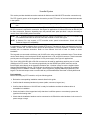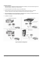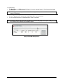
1
XX074-03
MODEL V1411X-DVC, V1411J-DVC AND
V1410X-DVC VARIABLE-SPEED KEYPADS
VICON INDUSTRIES INC., 89 ARKAY DRIVE, HAUPPAUGE, NEW YORK 11788
TEL: 631-952-CCTV (2288) FAX: 631-951-CCTV (2288) TOLL FREE: 800-645-9116
24-Hour Technical Support: 800-34-VICON (800-348-4266)
UK: +44 (0) 1489 566300 WEB: www.vicon-cctv.com
Vicon part number 8009-8074-03-00
Rev 208 Section 2
FCC Notice
Note: Complies with Federal Communications Commission Rules & Regulations Part 15, Subpart B for a
Class A digital device.
WARNING
This equipment generates and uses radio frequency energy and if not installed and used properly, that is, in
strict accordance with the manufacturer’s instruction, may cause interference to radio and television
reception. It has been type tested and found to comply with the limits for a Class A computing device in
accordance with the specification in subpart B of part 15 of the FCC rules, which are designed to provide
reasonable protection against such interference in a commercial installation. However, there is no guarantee
that interference will not occur in a particular installation. If this equipment does cause interference to radio
and television reception, which can be determined by turning equipment off and on, the user is encouraged to
try and correct the interference by one or more of the following measures:
•
Reorient the receiving antenna.
•
Relocate the equipment with respect to the receiver.
•
Relocate the equipment away from the receiver.
•
Plug the equipment into a different electrical outlet so that the equipment and receiver
are on different branch circuits.
If necessary, the user should consult the dealer or an experienced radio/television technician for additional
suggestions.
The user may find the following booklet prepared by the Federal Communications Commission helpful:
“Interference Handbook, Bulletin CIB-2”
This booklet is available from the U.S. Government Printing Office, Superintendent of Documents, Mailstop
SSOP, Washington, D.C. 20402-9328, ISBN 0-16-045542-1.
Warning: Power must be removed from this unit before removing circuit modules or ribbon cables.
Caution: This unit contains circuit cards with integrated circuit devices that can be damaged by static
discharge. Take all necessary precautions to prevent static discharge
Important
Safeguards
GRAPHIC SYMBOL EXPLANATION
12. Power Cord Protection - Power supply cords should not
be routed in trafficked areas or in tight spaces where they will
be pinched or used to bear weight. Allow some slack in the
cord where it enters the unit.
13. Outdoor Cable Grounding - Use only grounded outdoor
cables to protect against voltage surges and static charges.
Section 810 of the National Electrical Code, ANSI/NFPA 70-
The lightening bolt symbol alerts the user to the presence of
1984, provides information on proper grounding of the lead-in
dangerous voltage that may present the risk of electric shock.
wire to an antenna discharge unit, size of grounding conductors
and the requirements of grounding electrodes.
14. Lightning - Disconnect the product from its power source
and cable system when possible to prevent damage due to
lightning and power-line surges.
15. Power Lines - Do not locate outside cables over power or
utility lines where they can fall and make direct contact. Contact
with power lines can be fatal.
16. Overloading - Do not overload wall outlets and extension
cords to prevent risk of fire and electric shock.
The exclamation point symbol alerts the user to the presence of
17. Object and Liquid Entry - Never probe through, or spill
important operating and maintenance instructions.
liquid into, enclosure openings to prevent risk of fire or electric
shock.
1. Read Instructions - Read all safety and operating
18. Servicing - Refer all servicing to qualified service
instructions before the product is operated.
personnel.
2. Retain Instructions - Retain all safety and operating
19. Damage Requiring Service - Obtain service when:
instructions for future reference.
3. Heed Warnings - Pay attention to all product warnings.
a)
The power-supply cord or plug is damaged.
4. Follow Instructions - Follow all operating instructions.
b)
Objects have fallen or liquid has been spilled into the
product.
c)
The product is not designed for outdoor use and has been
exposed to water or moisture.
d)
The product does not operate per the operating
instructions. Perform Vicon recommended adjustments,
modifications and troubleshooting only to avoid unit
damage and personal injury.
e)
The product has been dropped.
f)
The product shows a significant change in performance.
20.
Replacement
5. Cleaning -(Do not use caustic, abrasive or aerosol
cleaners)
a)
b)
For units that CAN BE DISCONNECTED from the power
source, use a damp cloth for cleaning.
For units that CANNOT BE DISCONNECTED from the
power source, use a damp cloth for cleaning and do not
allow moisture or liquids to enter vents.
6. Attachments - Use only UL Listed Vicon recommended
attachments to prevent unit damage and personal injury.
7. Water and Moisture - Use only products designed for
outdoor environments where they will be exposed to water or
moisture.
8. Accessories - Do not place the unit on an unstable surface
to avoid falling. Use only UL Listed Vicon recommended mounting
accessories.
9. Ventilation - Do not block ventilating slots and openings as
they ensure reliable operation. Do not place the unit near a
heat source or into an enclosure unless recommended by
Vicon.
10. Power Sources - The product should only be operated
from the recommended power source. Use only a UL Class 2
indoor/dry or Class 3 outdoor/wet power supply.
11. Grounding - Only products equipped with a 3-prong
force a plug into a non-grounded outlet.
-
Use
only
Vicon
specified
damage and injury.
21. Safety Check - Request safety checks to be performed
following repair or maintenance to verify proper operation.
22. ESD Precaution - Take all normal electrostatic discharge
precautions to avoid component damage during installation and
operation.
23. For 230 VAC Devices Only - When the disconnect device
is not incorporated in the equipment or when the plug on the
power supply is intended to serve as the disconnect device,
follow the guidelines below:
a)
For permanently connected 230 VAC units, a readily
accessible disconnect device must be incorporated into
grounded plug should be inserted into a grounded power outlet.
Contact an electrician to replace an obsolete outlet. Do not
Parts
replacement parts or an approved equivalent to prevent unit
the site wiring.
b)
For 230 VAC units with a plug, the outlet must be installed
near the unit and be easily accessible.
Contents
Introduction .........................................................................................................................1
Configuration & Installation ...............................................................................................2
Passcode Setup...................................................................................................................8
Keypad Setup ......................................................................................................................9
Operation ...........................................................................................................................11
Operating Modes ..........................................................................................................................................11
Alarms ...........................................................................................................................................................11
Auxiliary Function Control ..........................................................................................................................11
Communication Failure ...............................................................................................................................12
Crosspoint Reset..........................................................................................................................................12
Lens Operation .............................................................................................................................................12
Presets...........................................................................................................................................................12
Manual Switching .........................................................................................................................................13
Salvos and Tours..........................................................................................................................................13
Sequential Switching ...................................................................................................................................13
Using the Joystick........................................................................................................................................14
Technical Information .......................................................................................................15
Shipping Instructions .......................................................................................................16
XX074-03-00 Rev 208 Variable-Speed Keypad
Contents • i
Introduction
Note: Read all of the instructions completely before installing or operating this equipment.
The information in this manual covers installation, programming and operation for the V1411X-DVC VariableSpeed Keypad and two alternate configurations, the V1411J-DVC and V1410X-DVC. The installation
procedures should only be performed by a qualified technician using approved materials in accordance with
national, state and local wiring codes. The unit complies with FCC standards for a Class A device and with
European Community EMC Directive 89/336/EEC and amendments 92/31/EEC. The product was subjected
to the testing outlined in European Normalization Standard (Emissions) EN 55022, A1: 1995 and A2: 1997
Class B, (Harmonic Emissions) EN61000-3-2: 1995, A1: 1998 and A2: 1998, (Flicker) EN61000-3-3: 1995
and (Immunity) EN50130-4: 1995 and A1: 1998.
The keypad operates as a standalone controller for dome/receivers without the need for matrix switchers or in
a multi-keypad installation using a Pilot/NOVA control system. The keypads can also be used with a
Kollector/ViconNet system.
The V1411X-DVC features:
•
Variable-speed joystick
•
Small physical footprint takes up less desktop space
•
Easy to read LCD panel provides system status
•
Large keypad buttons that are ergonomically designed for accurate key strokes
•
Passcodes to limit access (10 users and 1 manager are permitted).
V1411X-DVC
The V1411J-DVC features:
•
All of the features of the V1411X-DVC (except for a
change in joystick design and function)
•
Three-axis, variable-speed joystick adds zoom
capability to joystick operation.
V1411J-DVC
The V1410X-DVC features:
•
All of the features of the V1411X-DVC (same joystick function on 2-axis mini-joystick)
•
Smaller physical footprint than the V1411X-DVC.
V1410X-DVC
XX074-03-00 Rev 208 Variable-Speed Keypad
Introduction • 1
Configuration & Installation
Warning: Do not connect this unit to a power source until all connections are complete.
In the installation figures that follow, the V1411X-DVC is shown. The figures are applicable to all three
variations of the keypad (V1411X-DVC, V1411J-DVC and V1410X-DVC). The keypad is shipped with the
following accessories:
•
RJ-45 termination box and RJ-45 cable
•
Power supply.
You will use these items as shown on the following pages, which describe the two system configurations
available when using the keypad:
•
Standalone (no control system, receivers/domes may be connected)
•
NOVA (Pilot/NOVA or ViconNet control system or matrix switcher).
Power Requirements
A 12 VDC power supply is included for 120 VAC. For 230 VAC, a 9 VAC power supply is included. The two
leads will be connected to the RJ-45 termination box. You may connect the two leads to either of the
termination box screws shown in the figures to follow - polarity is not a factor for either the DC or the AC
supply.
Standalone
In a standalone system, there is no control system (CPU). You may connect receivers and domes directly to
the keypad in this configuration. The 4-wire half-duplex RS-422 protocol for the keypad is driven in a multidrop, tri-state manner that allows you to connect directly to SurveyorVFT domes, which use RS-485, without
the need for a converter box.
2 • Configuration & Installation
XX074-03-00 Rev 208 Variable-Speed Keypad
NOVA/Pilot
To use any of Vicon’s Pilot/NOVA control systems with the keypad, you will use NOVA configuration. You
may connect multiple keypads in this configuration, as shown in the example below.
The keypad is shipped with a 12 VDC power supply for 120 VAC units and a 9 VAC power supply for 230
VAC units. One power supply is required for each keypad in your system. Only the first keypad shows a
power supply in the figure below. The two leads from the power supply will be connected to the RJ-45
termination box. You may connect the two leads to either of the termination box screws shown below polarity is not a factor for either the DC or the AC supply.
Using RS-422 protocol,
connections are made keeping
like polarities and opposite
signal directions; for example,
Response Out - on each
keypad to Response In - at the
distribution line control.
XX074-03-00 Rev 208 Variable-Speed Keypad
Configuration & Installation • 3
You can also daisy chain keypads as shown below. Connect all like signals; for example, connect Command
In + on the first keypad’s RJ-45 box to Command In + on the second keypad’s termination box and so forth.
4 • Configuration & Installation
XX074-03-00 Rev 208 Variable-Speed Keypad
ViconNet System
This section provides detailed connection methods for Kollector and VN-NVR PTZ controller connection only.
The PTZ (joystick) portion of the keypad can be used to provide PTZ control of local and networked cameras
in the system.
NOTE: The other function buttons on the keypad are not supported by the driver of the Kollector or VN-NVR
unit.
A keypad can be directly connected to a Kollector Elite or VN-NVR unit. An RS-422 port or Serial (RS-232) to
RS-422 converter is required for connection. See Figure for applications. A Kollector Elite has an RS-422 port
for direct connection. However, depending upon the particular back panel provided, it may be necessary to
use the Vicon V422-CONV protocol converter.
NOTE: The 1st generation Kollector back panel does not support simultaneous use of a PTZ controller and
PTZ camera dome unless an RS-232 to RS-422 converter is used. See Figure.
NOTE: A Kollector Pro may support a PTZ controller under special circumstances. Check with Vicon
Technical Support for compatibility.
It is necessary to install a software driver to enable PTZ control. The minimum driver requirement is the Vicon
VN-DRV, revision 910. All later revision drivers will also support PTZ control operation. The driver must be
installed prior to hardware connection. Refer to Vicon manual XX113-56 or later for details on driver
installation.
The keypads are connected to Kollector and VN-NVR units using provided termination boxes. These boxes
can be wired directly to the back panel RS-422 terminal block or via an RS-232 converter. These boxes also
provide power to the keypad via the provided 12 VDC power supply. See Figure for applications.
The Vicon V422-CONV RS-422 to RS-232 converter can be used for applications requiring use of a serial
(COM) port for PTZ control. The converter plugs directly into the SERIAL port (DB-9 connector) and its
terminal block wired directly to the keypad’s termination box. ViconNet is setup to use the keypad in Main
Settings RS232/422/485 Controls. The COM port is configured in ViconNet Setup, selecting the available
COM port for the PC and the “Internal Comport”, which is joystick’s (keypad) address programmed in the
keypad. The internal comport must not conflict with any camera addresses. Baud rate is usually 9600 baud.
Pre-Installation
Before connecting any PTZ controller, verify the following points:
¾
Review the corresponding installation manuals listed in this guide.
¾
Confirm that all necessary hardware is present (cable, converters, keypad, etc.).
¾
Confirm that the Kollector or VN-NVR unit is ready for installation and that the software driver is
accessible for installation.
¾
Check the location of the keypad and verify that there is sufficient space to conveniently operate the
joystick while viewing video.
¾
Check that the installation hardware can be connected to a UPS with the other hardware in the event of a
power outage or surge.
XX074-03-00 Rev 208 Variable-Speed Keypad
Configuration & Installation • 5
Installation Guideline
1. With the Kollector or VN-NVR unit ready for PTZ controller installation, locate and install the keypad in its
permanent position, whether rack- or desk-mounted.
2. Locate and install the V422-CONV converter into the back panel.
3. Make all cable connections between keypad and back panel as shown in the Figure. If using the
converter, verify that the correct polarity is maintained on the terminal block connections.
4. With power applied to all items, setup Kollector or VN-NVR with the necessary PTZ software drivers and
test the PTZ capability of a local and remote camera dome.
5. Installation is complete.
Typical Installation Configurations
6 • Configuration & Installation
XX074-03-00 Rev 208 Variable-Speed Keypad
ViconNet Setup
● The Baud Rate and COM Address (9600 and 4 in screen example below) in ViconNet and the keypad
should match.
NOTE: COM address can be any address 1-64. When setting address, make sure it does not conflict with a
camera PTZ address.
nd
● For the 2 generation KE back panels: Under Port COM 1 must be selected.
st
● For the 1 generation KE back panels: Under Port COM 2 must be selected.
● For the VN-NVR back panel: Under Port COM 1 must be selected.
Note: The V422-CONV RS-422 to RS-232 converter must be used and plugs into the open COM port on rear
of the Kollector as illustrated in the installation figure.
Sample ViconNet Setup Screen
XX074-03-00 Rev 208 Variable-Speed Keypad
Configuration & Installation • 7
Passcode Setup
You may use passcodes to limit use of the keypad. Eleven passcodes are permitted, one for a manager and
ten users. The manager has access to all functions and setup parameters, including passcode setup. Only
the manager may setup the keypad using mode 4, which is discussed in the next chapter.
Note: From the factory, passcodes are disabled and the keypad can be immediately accessed. The manager
passcode must be set up in order to have user passcodes. The manager passcode is always passcode
1. Passcodes are defined to be 4 digits from the factory, but the manager can change this as
discussed in the Keypad Setup chapter. Do not begin a passcode with “0”.
To set up passcodes:
1. To enter Passcode Mode, perform the following keystrokes:
2. The LCD will display:
Edit Passcode 1
New Passcode ----
3. Passcode 1 is always the manager passcode. Enter the manager passcode and press
. If the keypad
sounder is enabled, as discussed in the next chapter, the keypad will beep twice when a new passcode is
entered.
4. The LCD will display:
Edit Passcode 2
New Passcode ----
5. Passcodes 2 – 11 are for users. Enter the 4-digit passcode for the first user, press
to save the
passcode and continue to set up passcodes if needed. Note that you do not have to use contiguous user
numbers; for example, you can skip passcode number 3 and continue setting up with passcode 4. To skip
a passcode during setup, or scroll through passcodes, use the A/I key.
6. To exit the Passcode Setup mode, perform the following keystrokes:
To edit passcodes, a manager must enter the passcode system and perform the steps above to change or
view the passcodes. Note that a user may edit his/her own passcode. To delete all passcodes, enter a master
passcode of all zeroes. To delete a user passcode only, enter all zeroes for that user passcode. To recover a
lost manager passcode (and retain the programmed user passcodes), contact Vicon Technical Support at 1800-34-VICON (1-800-348-4266, U.S.) or +44 (0) 1489 566330 (U.K.).
To log on to the keypad:
If passcodes have been entered into the system as defined above, you must enter a valid passcode to use
the keypad. After the initial startup screen, the keypad will display:
Vicon V1411X-DVC
Passcode? ---Enter a 4-digit passcode as defined above. Mode 4, Keypad Setup, may only be accessed by the manager.
8 • Passcode Setup
XX074-03-00 Rev 208 Variable-Speed Keypad
Note: If an alarm occurs when there is no user logged on to a passcoded keypad, the passcode line of the
display shown above will alternate between Passcode? ---- and Alarm. Enter a valid passcode and
acknowledge the alarm as discussed on page Error! Bookmark not defined..
To manually log off of the keypad, perform the following keystrokes
To automatically log off of the system, set a log off time as discussed in the next chapter. You must be a
manager to set the auto log off time. Use a time of zero seconds to disable this function.
To change the number of digits that will define the passcode length, refer to the Keypad Setup chapter.
Changing the passcode length clears all passcodes and disables the passcode mechanism.
Keypad Setup
Note: (For NOVA mode only.) Before powering your control system, perform the keypad setup described in
this chapter. Make sure to define the keypad baud rate (all keypads in your CCTV system must have
the same baud rate) and keypad address (each keypad must have a unique address). After you have
set up the keypad completely, power your control system and refer to its documentation to set the
Keypad State to Auto in the control system programming menus.
To enter Keypad Setup mode, perform the following keystrokes:
Then use the following methods to navigate through and choose a parameter:
Tilt up/down to display choices.
A/P to save your choice and
move to the next parameter.
A/I to move to the
parameter without saving.
next
To exit Keypad Setup mode, perform the following keystrokes:
Use the table on the next page to define the keypad settings.
Note: When you press A/P to store the contrast as listed in the following table, the joystick center position will also be
stored. Make sure that the joystick is at its center position before pressing A/P. Storing the contrast also initializes
the V1411J-DVC joystick’s zoom function. You must perform the contrast store procedure before you can zoom in
or out with the V1411J-DVC joystick, although zoom keys may be used without performing this procedure.
XX074-03-00 Rev 208 Variable-Speed Keypad
Keypad Setup • 9
Setup Parameter
Display Contrast
Address
Description
Sets the LCD contrast.
Sets the address for this keypad.
Baud Rate
Sets the communication baud rate. All keypads in your
Pilot/NOVA/ViconNet system must have the same baud
rate!
Determines the communications timeout in milliseconds
for single keypad operation only.
Turns sound ON or OFF. Beeps once for:
• illegal key sequence
• key sequence not completed in 10 seconds
• number out of range for NOVA mode
• passcode already used
• restoring factory defaults (slight delay before beep).
Beeps twice for:
• storing presets (operating mode 2)
• saving a choice during setup (modes 4 and 5).
Beeps four times when:
• one or more alarms activate.
Beeps every 15 seconds when:
• there are unacknowledged alarms in the system.
Audible indicator for key presses.
Recalls preset 1 (home) on the receiver in an alarm state
(Standalone mode only).
Automatically clears an alarm if it spontaneously
disappears. If this is OFF, you must press Alarm just as
you would with active alarms.
This applies to NOVA mode at 19.2 kbaud only. Do not
change this setting unless directed to do so.
Causes additional stop messages to be sent from the
joystick or lens keys when this key is released. Use 1 or
2 for receivers/domes using simplex.
Defines the length of time during which there is no
keyboard activity before the keypad logs off.
Sets the passcode length to 2, 4 or 6 digits. Changing the
length clears all passcodes and disables the passcode
mechanism.
PTZ functionality disabled when set to On.
Disables or enables the alarm (standalone mode only).
Press A/P to restore factory defaults and disable the
passcode system. This does not clear Display Contrast
settings. Factory defaults are: Address = 1, Baud Rate =
9600, Comms Timeout = 15 milliseconds, Sounder = On,
Key Click = On, Preset 1 on Alarm = On, Alarm Self
Clear = On, Pace Factor = 2, Additional Stops = 1, Auto
Log Off = disabled, Passcode Length = 4, PTZ Disable =
Off, Alarm Disable = Off.
Comms Timeout
Keypad Sounder
Key Click
Preset 1 On Alarm
Alarm Slf Clr
(Alarm Self Clear)
Pace Factor
Additional Stops
Auto Log Off
Passcode Length
PTZ Disable
Alarm Disable
Set Defaults
10 • Keypad Setup
Choices
(view the LCD window)
-(for Standalone
mode)
1-64
(for NOVA mode)
1200, 2400, 4800, 9600
baud, 19.2 kBaud
0 – 99 (default = 15)
On, Off
On, Off
On, Off
On, Off
0 – 20
0-6
-- (disabled), 1 – 60 min.
2, 4, 6 digits.
On, Off (default)
On, Off (default)
Not applicable.
XX074-03-00 Rev 208 Variable-Speed Keypad
Operation
Operating Modes
If passcodes are not active, mode 1 is automatically entered after power is applied or if the keypad is reset. If
passcodes are active, the passcode entry screen will display upon applied power or if the keypad is reset.
Refer to Indicators in Display in the Technical Information chapter for LCD status messages.
Alarms
Note: The procedure to clear all alarms is applicable for V1500 systems only.
Auxiliary Function Control
XX074-03-00 Rev 208 Variable-Speed Keypad
Operation • 11
Communication Failure
Note: The procedure to clear all failure announcements is applicable for V1500 systems only.
Crosspoint Reset
Note: To do a crosspoint reset, enter Dwell Mode (mode 3) and set 9999 or 9900 followed by A/P. Refer to
Accessing Operating Modes on previous page for how to enter Dwell Mode.
Lens Operation
Presets
Preset recall allows you to return to a pre-defined pan-and-tilt position (and zoom/focus settings, if the
camera includes a motorized zoom lens). The pan-and-tilt drive and lens must have preset potentiometers in
order to use preset functions. Presets must be stored (programmed) before they can be recalled.
Note: Adjust pan-and-tilt device and lens to desired settings before programming each preset.
12 • Operation
XX074-03-00 Rev 208 Variable-Speed Keypad
Manual Switching
Salvos and Tours
Note: Salvos and tours are not available in all control systems. Refer to your control system documentation if
necessary.
Sequential Switching
Note: Sequential switching is not available in all control systems. Refer to your control system documentation
if necessary.
XX074-03-00 Rev 208 Variable-Speed Keypad
Operation • 13
Using the Joystick
14 • Operation
XX074-03-00 Rev 208 Variable-Speed Keypad
Technical Information
PrePac Model Descriptions
Model Number
Product Code
V1411X-DVC
7518
V1411X-DVC-230
7518-01
V1411J-DVC
7832
V1411J-DVC-230
7832-01
V1410X-DVC
7847
V1410X-DVC-230
7847-01
Input Voltage
120 VAC
230 VAC
120 VAC
230 VAC
120 VAC
230 VAC
Power Supply
12 VDC at 500 mA.
9 VAC at 600 mA.
12 VDC at 500 mA.
9 VAC at 600 mA.
12 VDC at 500 mA.
9 VAC at 600 mA.
Electrical
Input Voltage:
Fuse:
Communications:
Cabling:
See PrePac Model Descriptions above. Note that you may also use a 9.5 VAC power
supply at 600 mA with 120 VAC units (not included).
Internal, self-resetting on power down.
RS-422, 4-wire half duplex.
RJ-45 socket on rear of keypad connected via 2 m RJ-45 cable to a breakout box. In
NOVA configuration, the connection from the breakout box to the matrix CPU must
be dual twisted pair, individually shielded cable such as Belden 8723. In Standalone
configuration, the cable requirements are the same although simplex
communications (a single twisted shielded pair) can be employed.
Controls
Numerical Keypad:
Camera Key:
Monitor Key:
Cancel Key:
Sequencing Key:
Programming Key:
Preset Key:
Zoom Keys:
Focus Keys:
Iris Keys:
Alarm Key:
Auxiliary Key:
Autoiris Key:
Autopan Key:
Lens Speed Key:
Joystick:
P/T Speed Key:
Display:
Indicators in Display:
Camera/monitor selection, dwell time input, mode selection, etc.
Assigns selected camera to selected monitor.
For monitor selection enabling.
Used to clear data entries.
Starts camera sequencing.
Used to change operating mode.
Recalls or stores preset position, depending on operating mode.
Manually zooms camera view in or out.
Manually focuses camera view near or far. Momentary switch.
Manually opens or closes camera’s iris. Momentary switch.
Acknowledges alarms.
Used to control auxiliary equipment.
Toggles automatic iris operation.
Toggles automatic panning operation.
Changes lens speed. Dependent upon receiver.
V1411X-DVC and V1410X-DVC: Causes pan-and-tilt mechanism to pan and tilt at
varying speed.
V1411J-DVC: Causes pan-and-tilt mechanism to pan and tilt at varying speed. Used
to zoom in/out at a selected fixed speed.
Reduces maximum pan-and-tilt speed by a factor of 4.
Backlit LCD displays 2 lines of 20 characters.
AI
ALARM
AP
AUX 1 2 3 4
CAM ####
COMFL (communication failure)
XX074-03-00 Rev 208 Variable-Speed Keypad
DWELL
MON ###
P (preset store mode)
PP ##
SNGL (standalone)
1300 (NOVA)
Technical Information • 15
Mechanical
V1411X-DVC and V1411X-DVC-230:
Construction:
Zinc plated steel.
Finish:
Black “walnut”.
Dimensions:
Height: 2.25 in. (57 mm).
Width: 11.5 in. (292 mm).
Depth: 6.9 in. (175 mm).
Weight:
3.0 lb (1.4 kg).
V1411J-DVC and V1411J-DVC-230:
Construction:
Zinc plated steel.
Finish:
Black “walnut”.
Dimensions:
Height: 3.0 in. (75 mm).
Width: 11.5 in. (292 mm).
Depth: 6.9 in. (175 mm).
Weight:
3.0 lb (1.4 kg).
Shipping Instructions
Use the following procedure when returning a unit to the factory:
1. Call or write Vicon for a Return Authorization (R.A.) at one of the locations listed below. Record the name
of the Vicon employee who issued the R.A.
Vicon Industries Inc.
89 Arkay Drive
Hauppauge, NY 11788
Phone: 631-952-CCTV (2288); Toll-Free: 1-800-645-9116; Fax: 631-951-CCTV (2288)
For service or returns from countries in Europe, contact:
Vicon Industries Ltd
Brunel Way
Fareham, PO15 5TX
United Kingdom
Phone: +44 (0) 1489 566300; Fax: +44 (0) 1489 566322
2.
Attach a sheet of paper to the unit with the following information:
a.
Name and address of the company returning the unit
b.
Name of the Vicon employee who issued the R.A.
c.
R. A. number
d.
Brief description of the installation
e.
Complete description of the problem and circumstances under which it occurs
f.
Unit’s original date of purchase, if still under warranty
3. Pack the unit carefully. Use the original shipping carton or its equivalent for maximum protection.
4. Mark the R.A. number on the outside of the carton on the shipping label.
16 • Shipping Instructions
XX074-03-00 Rev 208 Variable-Speed Keypad
Vicon Standard Equipment Warranty
Vicon Industries Inc. (the “Company”) warrants your equipment to be free from defects in material and workmanship under
Normal Use from the date of original retail purchase for a period of three years, with the following exceptions:
1.
2.
3.
4.
5.
VCRs, all models: Labor and video heads warranted for 120 days from date of original retail purchase. All other
parts warranted for one year from date of original retail purchase.
Video monitor CRT (cathode ray tube) and LCD monitors, all models: One year from date of original retail
purchase.
Uninterruptible Power Supplies: Two years from date of original retail purchase.
VDR-304 and VDR-308 Recorder Series: One year from date of original retail purchase.
Normal Use excludes prolonged use of lens and pan-and-tilt motors, gear heads, and gears due to continuous
use of “autopan” or “tour” modes of operation. Such continuous operation is outside the scope of this warranty.
Date of retail purchase is the date original end-user takes possession of the equipment, or, at the sole discretion of the
Company, the date the equipment first becomes operational by the original end-user.
The sole remedy under this Warranty is that defective equipment be repaired or (at the Company’s option) replaced, at
Company repair centers, provided the equipment has been authorized for return by the Company, and the return shipment
is prepaid in accordance with policy.
The Company will not be obligated to repair or replace equipment showing abuse or damage, or to parts which in the
judgment of the Company are not defective, or any equipment which may have been tampered with, altered, misused, or
been subject to unauthorized repair.
Software supplied either separately or in hardware is furnished on an “As Is” basis. Vicon does not warrant that
such software shall be error (bug) free. Software support via telephone, if provided at no cost, may be
discontinued at any time without notice at Vicon’s sole discretion. Vicon reserves the right to make changes to
its software in any of its products at any time and without notice.
This Warranty is in lieu of all other conditions and warranties express or implied as to the Goods, including any
warranty of merchantability or fitness and the remedy specified in this Warranty is in lieu of all other remedies
available to the Purchaser.
No one is authorized to assume any liability on behalf of the Company, or impose any obligations on it in connection with
the sale of any Goods, other than that which is specified above. In no event will the Company be liable for indirect, special,
incidental, consequential, or other damages, whether arising from interrupted equipment operation, loss of data,
replacement of equipment or software, costs or repairs undertaken by the Purchaser, or other causes.
This warranty applies to all sales made by the Company or its dealers and shall be governed by the laws of New York
State without regard to its conflict of laws principles. This Warranty shall be enforceable against the Company only in the
courts located in the State of New York.
The form of this Warranty is effective August 15, 2007.
THE TERMS OF THIS WARRANTY APPLY ONLY TO SALES MADE WHILE THIS WARRANTY IS IN EFFECT. THIS
WARRANTY SHALL BE OF NO EFFECT IF AT THE TIME OF SALE A DIFFERENT WARRANTY IS POSTED ON THE
COMPANY’S WEBSITE, WWW.VICON-CCTV.COM. IN THAT EVENT, THE TERMS OF THE POSTED WARRANTY
SHALL APPLY EXCLUSIVELY.
Vicon Part Number: 8006-9010-03-03 Rev 807
XX074-03-00 Rev 208 Variable-Speed Keypad
Vicon Standard Equipment Warranty • 17
Vicon Industries Inc.
Corporate Headquarters
89 Arkay Drive
Hauppauge, New York 11788
631-952-CCTV (2288) 800-645-9116
Fax: 631-951-CCTV (2288)
Vicon Europe
Headquarters
Brunel Way
Fareham, PO15 5TX
United Kingdom
+44 (0) 1489 566300
Fax: +44 (0) 1489 566322
Germany
vin-videotronic infosystems gmbh
Lahnstrasse 1
D-24539 Neumuenster
Phone: +49 (0) 4321 8790
Fax: +49 (0) 4321 879 47
Far East Office
Unit 5, 17/F, Metropole Square
2 On Yiu Street, Shatin
New Territories,
Hong Kong
(852) 2145-7118
Fax: (852) 2145-7117
Internet Address: www.vicon-cctv.com