1
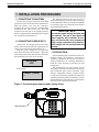
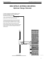
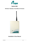
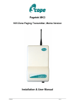
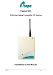
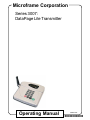
Microframe Corporation
Series 3007:
DataPage Lite Transmitter
Operating Manual
B3007-7012
*B3007-7012*
SERIES 3007
DATAPAGE LITE TRANSMITTER
INSTALLATION & SPECIFICATION GUIDE
ITEM NO: A3007-7012
REVISION DATE: 07/02
Microframe Corporation
604 S. 12th Street
Broken Arrow, OK 74012
Tel: (918) 258-4839
Toll Free: 1-800-635-3811
Website: www.microframecorp.com
E-mail: [email protected]
Merchandise Return
If your Unit does not work satisfactorily,
please give us a call. We may be able to clear up
the problem by phone. If it becomes necessary
to return your Unit to the factory, please
observe the following:
1. Place Unit in a sturdy box with sufficient
packing material.
2. If requested, include the power supply.
3. Return the system insured and prepaid
since we are not responsible for shipping damages and losses on returned Units.
Warranty Service
For warranty service, please contact
Microframe at 1-800-635-3811. A tech will
gladly assist you.
Assistance
For any product assistance or maintenance
help, contact Microframe by either calling 1800-635-3811 or emailing us at:
[email protected].
Safety
Do not install substitute parts or perform
any modification to the product without first
contacting Microframe.
Microframe Corporation
P.O. Box 1700
Broken Arrow, OK 74013
1-800-635-3811
Warning
All power transformers, line cords, and electrical equipment should be kept out of the reach
of children and away from water.
Life Support Policy
Microframe's products are not authorized for use as components in life support devices or systems without the express written approval of the president of
Microframe Corporation. As used herein:
1. Life support devices or systems are defined as systems which support or sustain life,
and whose failure to perform when properly
used in accordance with instructions for use
provided in the labeling, can be reasonably
expected to result in a significant injury to the
user or anyone depending on the system.
2. A critical component is any component of
a life support device or system whose failure to
perform can be reasonably expected to cause
the failure of the life support device or system,
or to affect its safety or effectiveness.
Disclaimer
We are constantly striving to improve our
products. Due to this, specifications are subject
to change without notice.
TABLE OF CONTENTS
DATAPAGE LITE SPECIFICATIONS .........................6
1 INSTALLATION PROCEDURES ...........................7
1.1 CONNECTING THE ANTENNA .......................7
1.2 CONNECTING POWER SUPPLY ....................7
1.3 PRECAUTIONS ...............................................7
2 OPERATION ...........................................................8
2.1 SENDING A BASIC PAGE ...............................8
2.2 SENDING A GROUP PAGE .............................8
2.3 PAGER TURN-OFF FROM BASE ...................8
2.4 TURNING OFF ALL PAGERS ..........................8
3 SYSTEM OVERVIEW .............................................9
3.1 DESCRIPTION ................................................9
3.2 RANGE EXPANSION ......................................9
3.3 IMPORTANT INFORMATION ............................9
3.4 SAFETY INFORMATION ..................................9
3.5 CARE OF TRANSMITTER ...............................9
3.6 LIABILITY .........................................................9
3.7 WARRANTY INVALIDATION ............................9
3.8 SERVICE INFORMATION ................................9
5 GEO PULSAR USER GUIDE ................................10
5.1 TURNING ON THE PAGER .............................10
5.2 SENDING A PAGE .........................................10
5.3 SENDING AN ALPHA MESSAGE ..................10
5.4 SENDING A NUMERIC MESSAGE ................10
5.5 RECEIVING A PAGE ......................................10
5.6 SENDING A GROUP CALL PAGE ..................10
5.7 MANUAL PAGER TURN-OFF .........................10
5.8 PAGER TURN-OFF FROM BASE ..................10
5.9 POWER CHECKING ......................................10
5.10 LIGHTING FUNCTION ...................................10
5.11 CAUTION ......................................................10
MINI DIPOLE ANTENNA MOUNTING ....................... 11
Series 3007 - DataPage Lite Transmitter
Microframe Corporation
DATAPAGE LITE SPECIFICATIONS
On-Premise Paging
Features
The DataPage Lite Transmitter can send a 12-digit
numeric message code to any of 9,999 different pagers.
Since you own the transmitter(s) and receivers, you can
enjoy unlimited paging with no monthly service fee.
Available for desk mount only.
Operation
The DataPage Lite is a simple plug and play system.
Once the transmitter is plugged in and batteries are
inserted into the pagers, the system is ready. A page is
transmitted when the pager number or group number is
entered using the number keys on the base. Pagers
may be turned off from the base or individually.
DataPage Lite Transmitter
Support and Sales
DataPage Lite Specifications
Frequency Range ...................................... 457.575 MHz or 457.550 MHz
TX Baud Rate ............................................ 1200
Distance Range ........................................ 1/4 to 1/2 Mile
FCC Approval No. ...................................... JRNUSASERILINK
Mounting ................................................... Desk Mounted
6
800-635-3811
Microframe® Corporation
www.microframecorp.com
P.O. Box 1700
Broken Arrow, OK 74013
Microframe Corporation
Series 3007 - DataPage Lite Transmitter
1 INSTALLATION PROCEDURES
1.1 CONNECTING THE ANTENNA
Connect the 90 degree antenna to the BNC
connector located at the side of the transmitter.
Slide the plastic cover over the connector,
engaging the two lugs into the corresponding
recesses in the side of the case. This will
maintain the antenna in an upright position,
which is important for optimizing the range of
the transmitter (See Figure 1).
1.2 CONNECTING POWER SUPPLY
Connect the AC adapter power lead to the
power socket located at the far right-hand rear
corner of the base station (See Figure 2).
Plug the power supply into a convenient
wall socket and turn on the power. When the
unit is first powered up, the system will display
the following screen for a few seconds:
DATAPAGE
LITE
Followed by:
PAGER: (1-9999)
>
The flashing cursor invites you to enter a
pager number (this can be any number between
1 and 9,999) after which you must press SEND
to transmit a page. See "Operation" for further
transmitting procedures.
IMPORTANT NOTE:
Use only the power supply included with
your system! The use of non-approved
power supplies will invalidate all warranty and service.We also recommend
using a surge suppressor for protection.
Power surges are not covered under the
warranty.
1.3 PRECAUTIONS
Avoid mounting the transmitter in the immediate vicinity of telephones, exchanges or
computer equipment. A few feet can make a
world of difference in avoiding interference
from the radio frequency generated by the
transmitter.
The performance of your system will be
affected by: foil backed wallboard, metal mesh,
wire-reinforced glass, metal sheeting, large
mirrors, suspended ceilings, elevator shafts,
etc. These can all reflect and thereby reduce the
signaling capability of the transmitter. A little
forethought prior to installation, coupled with a
few tests, will avoid most problems.
Figure 1: Connecting the Antenna and Locking Cover
BNC Connector
7
Microframe Corporation
2 OPERATION
2.1 SENDING A BASIC PAGE
In the most basic use of the transmitter,
simply type the pager number and then press
“SEND.” This will cause the pager with the
corresponding number to vibrate.
2.2 SENDING A GROUP PAGE
The pagers are capable of receiving both
indivual pages or a group page. To send a group
page, simply type the group call number instead
of the pager number in any of the paging steps
above. By default, the group call number is
"900," unless otherwise specified by the customer.
2.3 PAGER TURN-OFF FROM BASE
Enter the pager number followed by the
"ENTER" key. Press "ENTER" again to bypass
"Beep Type" screen. When screen reads "Enter
Mesage," type the code "((123456" followed by
"SEND." NOTE: The two left parenthesis
before the number are required, or it will
not work.
2.4 TURNING OFF ALL PAGERS
To simultaneously turn all pagers off at the
base, type in the group call number "900"
followed by "ENTER." Press "ENTER" again to
bypass "Beep Type" screen. When screen reads
"Enter Message," type the code "((123456" followed by "SEND."
* Please see instructions in the back of this
manual for particular pager use.
8
Series 3007 - DataPage Lite Transmitter
Microframe Corporation
Series 3007 - DataPage Lite Transmitter
3 SYSTEM OVERVIEW
3.1 DESCRIPTION
The Datapage Lite is a desktop transmitter
that can be used to transmit numeric messages
to individual pagers or even an entire group of
pagers. The system can accommodate up to
9,999 pagers. The transmitter base identity can
be configured to prevent interference with other
systems. This transmitter can also transmit an
out-of-range signal. This allows pagers to indicate when they are no longer within signal
range.
3.2 RANGE EXPANSION
The range and performance of this equipment can be improved by the addition of more
efficient antennas.* These can be installed
either inside or outside the building and are
connected to the transmitter with 50 OHM
coaxial cable.
The center-fed half wave dipole, measuring
approximately 12 inches from tip to tip, will
provide excellent all round local signalling. It is
a light duty antenna suitable for sheltered
environments/internal installation (LUHFDP).
It includes a 15 foot cable.
NOTE: High frequencies can equate to high
power losses. Always use quality cable. RG58 is
only acceptable on cable runs of up to 5 meters
(16.4 feet.) We recommend RG213, or equivalent, on greater lengths. If in doubt consult your
dealer.
*Subject to license conditions. Specifically,
mounting height and Effective Radiated Power
(ERP).
3.3 IMPORTANT INFORMATION
It is the purchaser's responsibility to determine the suitability of this equipment and its
derivatives for any given application.
Good working practice dictates that a suitable system installation log must be generated,
together with a record of the dates when the
system has been manually checked, (with the
aid of signal strength meters, etc.) enabling the
system performance to be compared with the
original installation data.
Do NOT subject this equipment to:
Mechanical shock
Excessive humidity or moisture
Extremes of temperature
Corrosive liquids
This equipment is designed for indoor use,
unless expressly stated otherwise, and must
not be used in classified Hazardous Areas,
including areas containing explosive or flammable vapors, unless express authorization has
been given in writing by the manufacturer. If
in doubt, consult your local product dealer for
further information.
Do not obstruct any slots or openings in the
product. These are provided for ventilation to
ensure reliable operation of the product and to
protect it from overheating.
3.5 CARE OF TRANSMITTER
Only use a damp cloth for cleaning (not
liquid or aerosol-based cleaners), and ensure
that any power is removed from the unit prior
to beginning the cleaning operation.
Removal of covers from the equipment must
only be undertaken by authorized service personnel, who must ensure that power is isolated
prior to removal.
3.6 LIABILITY
Scope and Microframe do not accept liability
for any damage or injury, caused as the result
of misuse of this equipment. It is the responsibility of the user to ensure that the equipment
is operated in the manner for which it was
intended, and that it is the correct item of
equipment for the required task.
3.7 WARRANTY INVALIDATION
Alteration or modification to any part of this
equipment, without the prior written consent
of the manufacturer, will invalidate all manufacturer approvals and warranties. No adjustments can be undertaken except by qualified
and licensed persons as defined by the FCC
Rules and Regulations. Operation of altered
equipment can result in fines, imprisonment,
and/or confiscation of such equipment.
3.4 SAFETY INFORMATION
These products are designed to operate safely
when installed and used according to general
safety practices. The following requirements
should be observed at all times:
3.8 SERVICE INFORMATION
If you experience a problem with your equipment, please contact Microframe at 1-800-6353811.
9
Series 3007 - DataPage Lite Transmitter
Microframe Corporation
5 GEO PULSAR USER GUIDE
5.1 TURNING ON THE PAGER
Hold down the “LARGE BLACK BUTTON”
until the pager comes on.
5.2 SENDING A PAGE
When the transmitter is turned on, the
prompt “PAGER (1-9999)” appears on the screen.
To send a page, enter the pager number on the
transmitter’s number pad followed by the
“SEND” key.
5.3 SENDING AN ALPHA MESSAGE
To send a pre-defined message to a pager,
enter the pager number followed by the “ENTER” key. You will be prompted for a “BEEP
TYPE (1-4).” Select 1-3 here and press the
“SEND” key. If no number is chosen, the pager
will default to Beep Type 4 (“PAGING”).
5.4 SENDING A NUMERIC MESSAGE
To send a numeric message to a pager,
simply enter the pager number followed by the
“ENTER” key. The transmitter screen will
display “BEEP TYPE.” Simply press “ENTER”
to bypass this. The transmitter screen will then
display “ENTER MESSAGE.” Using the number keys, enter up to a 16-digit numeric message followed by the “SEND” key. Note: Since
a numeric message is entered after the “BEEP
TYPE,” (pre-defined message) prompt, the alpha
message selected will be ignored.
5.5 RECEIVING A PAGE
The GEO Pulsar will start to vibrate when it
is paged. No action is necessary on the receiving end at this point. The pager will stop
vibrating after approximately 8 seconds. If the
user would like to stop the vibration before the
8 seconds, simply press the “LARGE BLACK
BUTTON.” If a numeric message is sent to the
pager, the message will be visible on the pager
screen until the pager stops vibrating. To view
the message after the pager has stopped vibrating, press the “LARGE BLACK BUTTON” once.
5.6 SENDING A GROUP CALL PAGE
All pagers respond to call number “900”
(unless another group call number has been
chosen). To page all pagers at once, simply
enter “900” and “SEND.”
10
5.7 MANUAL PAGER TURN-OFF
Press the “RIGHT ARROW BUTTON.” The
words “PGR OFF” will appear on the LCD
screen. Press the “LARGE BLACK BUTTON”
once to confirm. NOTE: If you have chosen to
disable the pagers’ on/off button, the pagers can
only be turned off from the transmitter.
5.8 PAGER TURN-OFF FROM BASE
Enter the pager number followed by the
“ENTER” key. Press “ENTER” again to bypass
“BEEP TYPE” screen. When screen reads
“ENTER MESSAGE,” enter the message code
“((123456” followed by “SEND.” NOTE: The
two left parenthesis before the number
are required, or it will not work. This "("
symbol is located to the left of the "0" key
and beneath the "7" key.
Since all pagers respond to call number
“900,” paging “900” with the message code
“((123456” will turn all pagers off.
5.9 POWER CHECKING
When the battery level is low, a low-battery
symbol will appear at the bottom of the pager
screen.
5.10 LIGHTING FUNCTION
Pressing the “LEFT ARROW BUTTON” for
one second can turn on the backlight on the
LCD screen. The light will shut off automatically after approximately 10 seconds, or the
user may turn the light off manually by pressing the “LEFT ARROW BUTTON” once.
5.11 CAUTION
a)
b)
c)
The pager is made up of LCD and
precision elements. Avoid water and
high temperature.
Remove the battery if the pager will not
be in use for a long period of time.
If the pager is not working properly, do
not dismantle or repair it yourself.
Microframe Corporation
Series 3007 - DataPage Lite Transmitter
MINI DIPOLE ANTENNA MOUNTING
Optional Range Extender
For optimum operation, the dipole radiators must be
positioned vertically, with the "E" symbol facing
downwards towards the ground.
Avoid mounting the dipole on or near to any metal
girders, pilars or other metallic obstructions.
The dipole should preferably be mounted at a height
which avoids potential snagging with any moveable
objects that might be used in the vicinity e.g. ladders.
Ensure that the bracket is firmly bolted to a solid
suface and that the feeder cable is adequately clamped
along it's entire run between the dipole and the transmitter/receiver.
E
GROUND
B3100\AX\9700
11
Series 3007 - DataPage Lite Transmitter
Microframe Corporation
Microframe Corporation
604 S. 12th Street
Broken Arrow, OK 74012
Tel: (918) 258-4839
Toll Free: 1-800-635-3811
Website: www.microframecorp.com
E-mail: [email protected]
12