1
EflIF
RST / RT / RM Series X
16mm Projectors
OPERATOR'S MANUAL
ELF AUDIO ViSUAL LIMITED,
836Yebv.iJRoad, Trading Estate, Slough, Berks.
I
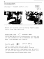
CAUTION
I
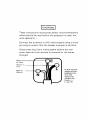
These instructions incorporate safety recommendations
which should be read before the projector is used, but
note especially :Connect the projector to AC mains supply using a threepin plug to ensure that the chassis is properly earthed.
Disconnect plug from mains socket before the rear
cover (secured with screws) is removed or the lamps
changed.
Green-and- Yellow__.----..._
to Earth
Brown to
....
Live
Blue to
Neutral
In due course
plugs will be
-marked only
E or the
electrical
symbol for
Earth -:!:- ;
l; and N.
ELF RST /RT/RM Series X
Simple Operation
Easy Maintenance
Trouble-free Use
This Operator's Manual is easy-to-read, informative and helpful.
Please read carefully before operating projector for the first time.
CONTENTS
Page
Main Parts of Your Projector
2
Explanation of Switch Plate
3
'.
Focusing
4
Threading
(RST Model)
5
Threading
(RT
Model)
6-
Threading
(RM
Model)
7
Projection
Rewinding'
o.
0
•
•
•
•
•
•
•
•
•
•
•
•
•
•
•
•
•
•
•
•
•
•
•
•
•
•
••
8
9
Changing Lamp
10
Silent Film Speed
11
Mag-Opt Projection'
12
Spare Parts & Accessories
13
Trouble Shooting
14
Cleaning & Maintenance'
15
General Specifications
'0'
••
0
0
•••••••••••••••••
16
2
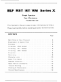
MAIN PARTS OF YOUR PROJECTOR
CD
@
@-@,--
@---
[ Model RST-3 ]
1. Handle
2. Arm Lock
3. Supply Arm
4. Film Channel &
Rewind Lever
5. Stil1 Picture Lever
6. Focus Knob .
7. Inching Knob
8. Lens
9. Framing Lever
10. Pilot Lamp
11. Automatic Threadlnq
Control Lever (RSTiRT)
12. Film Trimmer (RSTIRT)
13. Switch Plate
14. Elevator Knob
15. Power Cord
16. ,Take-up Arm
17. Lamp House
18. Auto Take-up Guide (RST)
3
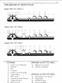
EXPLANATION OF SWITCH PLATE
Model RST / RT / RM-O, 1
Model RST / RT / RM-2
®
--
\
-
Model RST / RT / RM-3
All Models
Additional on RST / RT / RM-2
1.
2.
3.
4.
5.
6.
7.
8.
9.
10.
11. Magnetic Playback
12. Optical Playback
Lamp Low (Reverse)
Reverse
Off
Forward
Lamp Low (Forward)
Lamp High (
)
MIC Input
Volume & Amp Switch
Treble Control
Bass Control
Additional on RST / RT / RM-3
13.
14.
15.
16.
Recording Lock Button
Recording
PHONO Input
Level Indicator
4
FOCUSING
Turn ROTARY SWITCH to
FORWARD position )
and LAMP position. { , )
A
B
Raise projector if required by turning black
elevator knob
(photo A) on front of projector.
When screen is illuminated and is of the correct size, focus
(photo B) so edge of light is sharp.
Switch OFF. ( 0 )
SCREEN SIZE CHARTS IN INCHES
8'
12'
10'
15'
20'
25'
I 30'
I
H
1"
W
H
1.5"
W
2'2"
2'11 "
2'9"
3'8"
3'4"
4'5"
1'5"
1'11"
1'10"
2'5"
1'4"
1'10"
2'2"
2'11"
H
2.0"
W
3.0"
H
W
4.0"
H
1'8"
2'2"
4'2"
5'7"
2'9"
3'8"
2'1 "
2'9"
8'4"
11'3"
5'7" I 6'11"
9'4"
7'5"
3'8"
4'7"
4'11"
6'2"
2'9"
3'8'
9'9"
13'1 " i
6'6" I 7'5"
8'9"
10'0"
5'7"
7'6"
4'2"
3'5"
4'8" I 5'7"
2'3"
2'9"
3'1"
3'8"
1'8" I 2'1 "
2'3"
2'9"
I
W
3'3"
3'8"
41 .
2'5'
3'3"
29
3:8'
i 4'4
SCREEN SIZE CHARTS IN METERS
3m
5
10
15
20
25
30
40
38mm
H
W
0.56
0.76
0.94
1.26
1.89
2.53
2.84
3.80
3.79
5.07
4.74
6.34
5.69
7.61
7.58
10.15
50
H
W
0.43
0.57
0.72
0.96
1.44
1.93
2.16
2.89
2.88
3.86
3.60
4.82
4.32
5.79
5.76
7.72
65
H
iW
0.33
0.44
0.55
0.74
1,1:
1.66
2.22
2.21
2.96
2.77
3.71
3.32
4.45
4.43
5.93
76
0.28
0.38
0,47
J'3.3
42E
1.42
1.90
1.89
2.53
2.37
3.17
2.84
3.80
3.79
5.07
0.2'
:30:
02i:
1.08
1.44
1.44
1.93
1.80
2.41
2.16
2.89
2.88
3.86
100
H
W
--
5'/"
I 7'5"
I
I
45'
35
Lens
I
i
I
8'4"
11'3"
6'3'
85
I
9'4'
12"5
.:.
.;
:-=
4 :3
42
.:.
5
I 9'4" I
5
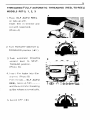
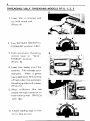
THREADING/FULLY AUTOMATIC THREADING (REEL-TO-REEL)
MODELS RST-O, 1, 2, 3
A
1. Place ELF AUTO REEL
on take-up arm.
Insert film in trimmer and
cut with raised end.
(Photo A)
2. Turn ROTARY SWITCH to
FORWARD position (<<±! ).
3. Push
automatic threading
control
lever
to
SE LF-
THREAD position.
(Photo B).
4. Insert film leader into film
channel. (Photo B)
Film threads .... ELF AUTO
REEL takes up film
.
and the automatic threading
guides release automatically.
5. Switch OFF. ( 0)
B
6
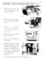
_THREADING / SELF THREADING MODELS RT-O, 1, 2, 3
A
1. Insert film in trimmer and
cut with raised end.
(Photo A)
2. Turn ROTARY SWITCH to
FORWARD position ( ).
3. Push automatic threading
B
control lever to "SELFTHREAD'/ position.
(Photo B).
4. Insert film leader into Film
channel. Film threads automatically.
When a gentle
tug is applied to film coming
off last roller, the automatic
threading guides wi II release.
(Photo C)
5. When
sufficient
film has
passed through projector to
reach take-up reel, SWITCH
OFF (0).
6. Attach leading edge of film
on to take-up reel.
c
7
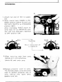
THREADING / MANUAL THREADING MODELS RM-O, 1, 2, 3
A
1. Swing lens away from projector by pulling on lens
holder. (Photo A)
8
2. Open both sprocket shoes.
and rubber roller. (Photo
A, B)
3. Thread
film
THREADING
following
DIAGRAM.
Raise rubber guide roller as
necessary.
4. Close both sprocket shoes
and lens holder.
5. Be sure film is seated properly in gate.
c
6. Check threading by turning
inching knob. When knob is
turned by pushing UP,film
should move forward intermittently in film gate and
both upper and lower loops
will be maintained.
(Photo C)
7. Attach leading edge of film on to take-up reel
8
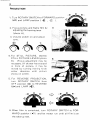
PROJECTION
1. Turn ROTARY SWITCH to FORWARD position
and LAMP position ( ).
I
2. Focus picture, and frame film by
adjusting the framing lever
o
A
(photo A).
3. Volume switch on and adjust
tone.
tC>>>
?:
6'6'6'
4. For STI LL PICTURE, depress
STI LL PICTURE LEVER (photo
B). (Focus adjustment may be
necessarv.) If shutter has stopped
in front of picture, it may be
moved by turning inching knob
either direction unti I picture
shows on screen.
B
5. For REVERSE PROJECTION,
turn ROTARY SWITCH from
OFF position (O) to REVERSE
and LAMP 6. When film is completed, turn ROTARY SWITCH to FORWARD position the take-up reel.
and let motor run until all film is on
9
REWINDING
A
1. Attach tail end of film to supply
reel.
2. Move rewind lever DOWN to REWI NO position (photo A) .and turn
ROTARY SWITCH to FORWARD
position ).
After rewinding, FIRST return rewind lever UP to OPERATE position and turn ROTARY SWITCH
to OFF position (0 ).
'it
Rewinding
I
Return rewind lever UP
to OPERATE
B
3. After removing reels from arms,
depress arm locking buttons
(photo B) and lower arms
4. Replace projector cover to carry.
The flexible plastic cover should be
used to protect projector and to
carry take-up reel, spare lamp,
speaker cord, etc.
)
10
CHANGING LAMPS
DISCONNECT POWER SUPPLY CORD
A
B
Remove lamp-house lock screw near the top of aperture plate.
Pullout on top edge of lamp-house.
PROJECTION LAMP
(ELC/24V 250W)
Push (to left) ejection lever immediately below lamp and lamp
will come out (photo A).
Be sure replacement lamp snaps into
place. Proper seating of lamp is essential.
EXCITER LAMP
(SR K/4V O.75A)
Pullout on black exciter lamp cover (photo B).
Push in on lamp and turn counter-clockwise to remove.
Insert new lamp with notch on base flange in upper right position.
turn clockwise, clean fingerprints from lamp, and replace cover.
Close lamp-house door and replace lock-in screw.
11
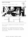
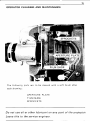
SILENT FILM SPEED
DISCONNECT POWER SUPPLY CORD
SOUND
SI LENT
Shutter
Shutter
--oVJ
Motor
Motor
This is changed by slipping the motor drive belt to the alternate
set of pu Ileys
Open rear cover. Turn inching knob at the same time guiding
the belt first to the smaller motor pulley then to the larger
shutter pulley.
Change back to sound speed by reversing the
above procedure.
(Note. No silent speed on 50/60 Hz models.)
12
MAG-OPT PROJECTION
On the RST-2, 3, RT-2, 3, RM-2, 3 Models, either magnetic or
optical sound tracks may be played back.
MO°
MAGNETIC
PLAYBACK
MO°
OPTICAL
PLAYBACK
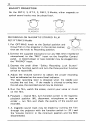
RECORDING ON MAGNETIC STRIPED FI LM
RST/RT/RM-3 Models
1. Put OPT-MAG knob to the Optical position and
thread film in the projector in the normal manner,
then set the knob to Recording position.
M
©
MAGNETIC
RECORDING
2. Connect the supplied microphone (or any 50k Ohm impedance
microphone) to the "MIC" input on the Amplifier Control
panel. A record player or tape recorder may be plugged into
the "PHONO" input.
3. Depress the small silver "Safety Recording Lock Button"
below the function switch and turn the three-position function
switch to record (R).
4. Adjust the Volume Control to obtain the proper recording
level as indicated on the record level indicator.
The best recording level is obtained when the needle just
touches the red line. If the needle is allowed to swing into
the red area, the recorded sound may be distored.
5. Run the film, watch the screen, record your voice or music
on the film.
6. Playback - rewind film, turn function switch to the magnetic
playback position (M), disconnect microphone or tape recorder - run film and check the quality of the sound just
recorded.
7. A magnetic sound track may be erased by running the film
through the projector with the function switch in ( R ) and
the Volume Control in the minimum position and the MIC
disconnected.
13
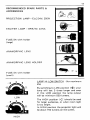
RECOMMENDED SPARE PARTS &
ACCESSORIES
PROJECTION LAMP - ELC/24V, 250W
EX'CITER LAMP - BRK/4V, 0.75A
FUSE/2A with holder
(large)
ANAMORPHIC LENS
ANAMORPHIC LENS HOLDER
FUSE/2A with holder
(small)
LAMP HI-LOW SWITCH (for maximum
life)
LOW
a
HIGH
By switching to LOW position ( your
lamp will last 3 times longer and even
in this LOW position the lamp output
will be minimum 550 lumens.
The HIGH position ( <J:) should be used
for larger audiences, or when room light
is too bright.
In HIGH position the projector light will
be about 750 lumens on the screen.
14
TROUBLE SHOOTING
Here IS a non-Proresslonal/s gUIde for /oca t/rtq
rn/nor
o roo/erns ,
In nearly every case, a simple aefjustment rs all that IS necessary
to restore peak efficIency.
NO POWER TO MOTOR
1. Make sure power cord is con-
OR LAMP
nected to wall outlet and that
outlet has power.
2. Check power cord and repair if
necessary.
MOTOR RUNS, BUT PROJECTION LAMP DOES
NOT LIGHT
1. Check position of rotary switch.
2. Replace projection lamp.
FILM DOES NOT RUN,
BUT MOTOR AND
LAMP BOTH OPERATE
1. Raise STILL PICTURE
LEVER to operate.
2. Check Motor Belt.
NO SOUND
1. Turn amplifier switch on and
increase volume.
2. Plug in speaker. (On models
with removable speaker.)
3. On models with magnetic reproduction be sure I'M-O"
switch is in proper position.
4. Replace exciter lamp if lamp
does not light.
5. Check 2 A fuse & replace if
necessary.
POOR SOUND
1. Check position of volume control.
2. Rethread film.
3. Clean exciter lamp.
4. Fi 1m may be defective, use new
film if necessary.
POOR PICTURE
1. Check
2.
3.
4.
5.
threading, rethread if
necessary.
Clean projection lens with soft
tissue, both front and rear.
Refocus lens.
Clean gate with soft bristle brush.
Film may be defective, use new
film if necessary.
15
OPERATOR CLEANING AND MAINTENANCE
The followi ng parts are to be cleaned with a soft brush after
each showi ng :
APERTURE PLATE
FILM SHOE
SPROCKETS
Do not use oil or other lubricant on any part of the
Leave this to the service engineer.
oroiector:
16
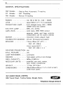
GENERAL RST Models
·Reel-to-Reel Automatic Threading
RT
Self Threading
Models
RM Models
Manual Threading
AC. 50 or 60 Hz., 430 - 450W
POWER
LENS
· · .. super 50mm (2") f1.2 (standard)
·
PROJECTION LAMP · ... E LC Halogen lamp, 24V - 250W
(200W lamp also usable)
EXCITER LAMP
··
AMPLIFIER
BRK, 4V-0.75A
solid state, 25W RMS output
separate treble and bass controls
independent use for public address
MOTOR
induction motor, plug-in type
FRAMES PER SECOND.. 24 and 18 (sound and silent)
SPEAKER
13cmx20cm (5"x8")
.
RST, RT, RM-O
16cm round (6.5")
RST, RT, RM-1, 2, 3
REVERSE PROJECTION. yes
STI LL PICTURE. · · · · ... yes
LOOP RESTORE R. · · · .. automatic
REWIND. ·
·
high speed, without reel change
REE L CAPACITY. · ·
MODU LAR UN ITS· .
WEIGHT
DIMENSIONS
600m (2,000 tt)
·.·
amplifier, cam tank, motor,
lens holder, transformer
17 Kgs. (37.4Ibs.)
· · · .. 29cmx35cmx35cm (11.4"x 13.8"x 13.8")
(with front cover)
ELF AUDIO VISUAL LIMITED,
836 Yeovil Road, Trading Estate, Slough, Berks.
Telephone: Slough 36123/5
Printed by W & B Litho & Letterpress Printers. Hayes Place, West Street, Marlow.