1
Operator's
Manual
M
4-Cycle
Electric
Start Capable
WEEDWACKER® GAS TRIMMER
Model No. 316.731971
_EU_VA#LE
$ TA R TR N _ E A $ E
* SAFETY
* ASSEMBLY
* OPERATION
CAUTION: Before using this product,
read this manual and follow all its Safety
Rules and Operating
instructions.
Sears Brands
Management
. ESPANOL, R 19
Corporation,
Visit our website:
769-09412 / 00
* MAINTENANCE
Hoffman
Estates,
IL 60179 U.S.A.
www.craftsman.com
10/13
TABLEOFCONTENTS
Safety...............................................
2
Warranty.............................................
5
KnowYourUnit........................................
6
Specifications
.........................................
6
Assembly
.............................................
7
OilandFuel...........................................
9
Starting
andStopping
..................................
10
Operation
............................................
12
Maintenance
.........................................
13
Cleaning
andStorage..................................
16
Troubleshooting
.......................................
17
Repair
Protection
Agreements
...........................
18
Service
Numbers..............................
BackCover
Allinformation,
illustrations
andspecifications
inthismanual
arebased
onthelatestproduct
information
available
atthetimeofprinting.
We
reserve
therighttomakechanges
atanytimewithout
notice.
©Seam
Brands,
LLC
Thepurpose
ofsafetysymbols
istoattractyourattention
to
possible
dangers.
Thesafetysymbols,
andtheirexplanations,
deserve
yourcareful
attention
andunderstanding.
Thesafety
warnings
donotbythemselves
eliminate
anydanger.
The
instructions
orwarnings
theygivearenotsubstitutes
forproper
accident
prevention
measures.
i SYMBOL
MEANING
DANGER.
•
Signals an EXTREME hazard.
Failure to obey a safety DANGER signal WILL result in
serious injury or death to yourself or to others.
WAR N ING:
Failure to obey a safety WARNING signal CAN result in
a SERIOUS hazard.
serious injury to yourself orSignals
to others.
CAUTION.
.
Signals a MODERATE hazard.
Failure to obey a safety CAUTION signal MAY result in
property damage or injury to yourself or to others.
NOTE: Advises you of information or instructions
operation or maintenance of the equipment.
vital to the
SPARK ARRESTOR NOTE
NOTE: For users on U.S. Forest Land and in the states of
California, Maine, Oregon and Washington. All U.S. Forest Land
and the state of California (Public Resources Codes 4442 and
4443), Oregon and Washington require, by law that certain internal
combustion engines operated on forest brush and/or grass-covered
areas be equipped with a spark arrestor, maintained in effective
working order, or the engine be constructed, equipped and
maintained for the prevention of fire. Check with your state or local
authorities for regulations pertaining to these requirements. Failure
to follow these requirements could subject you to liability or a fine.
This unit is factory equipped with a spark arrestor, if it requires
replacement, contact a Sears Parts & Repair Service Center to
install the appropriate muffler assembly.
CALiFORNiA
PROPOSiTiON
65
WARNING:
Engine exhaust, some of its
constituents and certain finished components contain or
emit chemicals known to the State of California to cause
cancer and birth defects or other reproductive harm. Wash
hands after handling.
Read the operator's manual and follow all warnings and safety
instructions.
Failure to do so can result in serious injury to the
operator and/or bystanders.
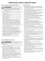
• iMPORTANT SAFETY iNSTRUCTiONS
READ ALL iNSTRUCTiONS
BEFORE OPERATING
WHILE OPERATING
Wear safety glasses or goggles that meet current ANSI / ISEA
Z87.1 standards and are marked as such. Wear ear/hearing
protection when operating this unit. Wear a face mask or dust
mask if the operation is dusty.
Wear heavy long pants, boots, gloves and a long sleeve shirt. Do
not wear loose clothing, jewelry, short pants, sandals or go
barefoot. Secure hair above shoulder level.
WAR N ING.
When using the unit, all safety
rules must be followed. Please read these instructions
before operating the unit in order to ensure the safety of
the operator and any bystanders.
Please keep these
m
instructions for later use.
•
•
The cutting head shield must always be in place while operating
the unit. Do not operate the unit without both trimming lines
extended and the proper line installed. Do not extend the
trimming line beyond the length of the shield.
This unit has a clutch. The cutting head remains stationary when
the engine is idling. If it does not, take the unit to a Sears or
other qualified service dealer for an adjustment.
Adjust the handle to provide the best grip, if applicable.
Make sure the attachment is not in contact with anything before
starting the unit.
Use the unit only in daylight or good artificial light.
Avoid accidental starting. Be in the starting position whenever
pulling the starter rope. The operator and unit must be in a stable
position while starting. Refer to Starting and Stopping.
Use the right tool. Only use this tool for its intended purpose.
Always hold the unit with both hands when operating. Keep a
firm grip on both handles or grips.
Do not overreach. Always keep proper footing and balance. Take
extra care when working on stairs, steep slopes or inclines. To
avoid serious injury, do not operate the unit while on a ladder or
a roof.
Read the instructions carefully. Be familiar with the controls and
proper use of the unit.
Do not operate this unit when tired, ill or under the influence of
alcohol, drugs or medication.
Children must not operate the unit. Teens must be accompanied
and guided by an adult.
All guards and safety attachments must be installed properly
before operating the unit.
Inspect the unit before use. Replace damaged parts. Check for
fuel leaks. Make sure all fasteners are in place and secure.
Replace parts that are cracked, chipped, or damaged in any
way. Do not operate the unit with loose or damaged parts.
Only use the trimming line described in the Specifications section
of this manual. Never use metal-reinforced line, wire, chain or
rope. These can break off and become dangerous projectiles.
Do not replace the cutting head with rigid or metal blades. Doing
so could result in serious injury.
Be aware of risk of injury to the head, hands and feet.
Carefully inspect the area before starting the unit. Remove
rocks, broken glass, nails, wire, string and other objects that
may be thrown or become entangled with the unit.
Keep hands, face, and feet away from all moving parts. Do not
touch or try to stop moving parts.
Do not touch the engine, gear housing or muffler. These parts get
extremely hot from operation, even after the unit is turned off.
Do not operate the unit faster than the speed needed to do the job.
Do not run the unit at high speed when not in use.
Do not force the unit. It will do a better, safer job when used at
the intended rate.
Clear the area of children, bystanders and pets; keep them
outside a 50-foot (15 m) radius, at a minimum. Even then, they are
still at risk from thrown objects. Encourage bystanders to wear
eye protection. If you are approached, stop the unit immediately.
Squeeze the throttle control and check that it returns
automatically to the idle position. Make all adjustments or
repairs before using the unit.
This unit is intended for occasional, household use only.
Always stop the unit when operation is delayed or when walking
from one location to another.
If you strike or become entangled with a foreign object, stop the
unit immediately and check for damage. Do not operate the unit
before repairing damage. Do not operate the unit with loose or
damaged parts.
Turn the engine to off and disconnect the spark plug for
maintenance or repair.
Use only original equipment manufacturer (OEM) replacement
parts and accessories for this unit. Use of any other parts or
accessories could lead to serious injury to the user, or damage
to the unit, and void the warranty.
Keep the unit clean. Carefully remove vegetation and other
debris that could block moving parts.
To reduce fire hazard, replace a faulty muffler and spark arrestor.
Keep the engine and muffler free from grass, leaves, excessive
grease or carbon build up.
If the unit starts to vibrate abnormally, stop the unit immediately.
Inspect the unit for the cause of the vibration. Vibration is
generally an indicator of trouble.
SAFETY WARNINGS FOR GAS UNITS
WARNI NG:
its vapors can explode if ignited. Take the following
Gasoline is highly flammable
precautions:
and
Store fuel only in containers specifically designed and approved
for the storage of such materials.
Always stop the engine and allow it to cool before filling the
tank. Never remove the fuel tank cap or add fuel when the
engine is hot. Always loosen the fuel tank cap slowly to relieve
any pressure in the tank before fueling.
Always add fuel in a clean, well-ventilated outdoor area where
there are no sparks or flames. DO NOT smoke.
Never operate the unit without the fuel cap securely in place.
Avoid creating a source of ignition for spilled fuel. Wipe up any
spilled fuel from the unit immediately, before starting the unit.
Move the unit at least 30 ft. (9.1 m) from the fueling source and
site before starting the engine. DO NOT smoke.
Never start or run the unit inside a closed room or building.
Breathing exhaust fumes can kill. Operate this unit only in a well
ventilated outdoor area.
3
OTHERSAFETYWARNINGS
Store the unit in a dry place, secured or at a height to prevent
unauthorized use or damage. Keep the unit out of the reach of
children.
,i, All service, other than the maintenance procedures described in
this manual, should be performed by a Sears or other qualified
service dealer.
Before inspecting, servicing, cleaning, storing, transporting
replacing any parts on the unit:
1. Stop the unit.
Never douse or squirt the unit with water or any other liquid.
Keep handles dry and clean (free from debris, oil and grease).
Clean the unit after each use. Refer to Cleaning and Storage. Do
not use solvents or strong detergents.
Keep these instructions. Refer to them often and use them to
instruct other users. If you loan this unit to others, also loan
them these instructions.
or
2. Make sure all moving parts have stopped.
3.Allow the unit to cool.
4. Disconnect the spark plug wire.
Secure the unit while transporting.
Never store the unit with fuel in the tank, inside a building where
fumes may reach an open flame (pilot lights, etc.) or sparks
(switches, electrical motors, etc.).
,, SAFETY
SAVE THESE INSTRUCTIONS
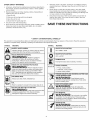
& iNTERNATiONAL
SYMBOLS
,,
This operator's manual describes safety and international symbols and pictographs that may appear on this product. Read the operator's
manual for complete safety, assembly, operating and maintenance and repair information.
SYMBOL
MEANING
SYMBOL
!
O
',, SAFETY ALERT SYMBOL
Indicates danger, warning or caution. Maybe Used in
. conjunct on wth other symbo sorp ctographs
i:::lm
,READ
OPERATOR'S
MANUAL
WARNING. Read
the
0Perator,
s
[]
manual(s) and follow all warnings and safety
I instructions, Failure tOdo so can Jesuit in serious
= injury to the operator and/or bystanders.
=
[_[Jl
WARNING.
. PRIMER
BULB
_
Push primer bulb, ful y and slowly, 10 times.
.
121I-,:1I_l
Thrownob
ectsaod,oud
heaiing loss:
Z8% arleYenPd
°rlc_ct,ao_ e_e_ rol eC_it:entwhAe
Nsol/p_rSEiA g
this unit. Use afull face shield when needed.
-L.=7 J
' ON/OFF
STOP
CONTROL
ON / START
/ RUN
o WEAR EYE AND HEARING PROTECTION
t
_v
MEANING
UNLEADED
FUEL
Always use dean, fresh unleaded fuel,
3. o RUN choke position
"-_,,_..,,at ' THROWN OBJECTS AND ROTATING CUTTER CAN
//_---_,
CAUSE SEVERE'NJURY
objects can be
-_"
propelled at high speed, causing injury. Keep away
WARNING:•sma
from the rotating rotor.
,,,OiL
Refer t0 Operator S manual for the pr0per type Of oil
4, DONOT
A
'. KEEP BYSTANDERS AWAY
WARN
especially
USE E85 FUELIN THIS UNIT
! N G; Keepa,,bystanders
children and pets, at least 50 feet (15 m)
. from the operating area.
WARN IN •
c_ontaign
i2g ig!iate rnethanndlO:f_ _thhtnw:lrWilnlt
_ke!y
i
,,
WAdRr.
yoNu_maN_et b Do dotthuch lht t me_ffer
,, HOT SURFACE
[]
y"
e.
yg
ul e .
p
g
extremely hot from operation. When turned off they
remain hot for a short time.
, SHARP BLADE
"_
•
WhAme_nt
sNhi_No_r_vSht_rboladl
a a
" d.$ p
i
• touch the line cutting blade.
tr _2eor t
"°nj ry,
CRAFTSMAN
TWO
YEAR FULL
WARRANTY
FOR TWO YEARS from the date of purchase, this product is warranted
will receive free repair or replacement if repair is unavailable.
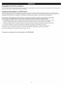
ADDITIONAL
LIMITED WARRANTY
on TRIMMER
against any defects in material or workmanship.
A defective product
SHAFTS
FOR THE THIRD THROUGH TENTH YEAR from the date of purchase, the outer metal housing of the upper and lower trimmer shafts is
warranted against any defects in material or workmanship. With proof of purchase, a new housing will be supplied free of charge. You are
responsible for the labor cost of installation. This additional coverage does not apply to inner trimmer shaft components.
For warranty coverage details to obtain free repair or replacement, visit the web page: www.craftsman.com/warranty
This warranty covers ONLY defects in material and workmanship.
Warranty coverage does NOT include:
•
Expendable items that can wear out from normal use within the warranty period, such as cutting line, spark plugs, or filters.
•
Product damage resulting from user attempts at product modification or repair or caused by product accessories.
•
Repairs necessary because of accident or failure to operate or maintain the product according to all supplied instructions.
•
Preventive maintenance, or repairs necessary due to improper fuel mixture, contaminated or stale fuel.
This warranty is void if this product is ever used while providing commercial services or if rented to another person.
This warranty gives you specific legal rights, and you may also have other rights which vary from state to state.
Sears Brands Management
To order parts or schedule
Corporation,
Hoffman Estates, IL 60179
service for this product, call 1-800-469-4663.
5
APPLiCATiONS
Asatrimmer:
• Cutting
grassandlightweeds.
• Edging
• Decorative
trimming
around
trees,fences,
etc.
Otheroptional
accessories
maybeusedwiththisunit.
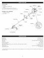
ASSEMBLY
•
•
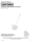
TOOLS
Spark Plug
Muffler
Primer
Shaft Gri
REQUIRED:
On/Off
#2 Phillips screwdriver
3/8" Socket
Handle
Starter
Rope Grip
Switch
Bulb
Fuel Cap
\
Choke Lever
Air Filter
Cover
Throttle
Control
Shaft Housing
Coupler
Oil Fill Pluc
Cutting Head
Shield
Cutting
Head
Line Cutting
Blade
Engine Type ........................................................................................
Displacement .......................................................................................
Spark Plug Gap ....................................................................................
Spark Plug .........................................................................
Lubrication ................................................................................................
Crankcase Oil Capacity .................................................................................
Fuel Tank Capacity ......................................................................................
Approximate Unit Weight (No fuel, with cutting head, cutting head shield and handle) ..........................
Trimmer Mechanism .................................................................................
Trimming Line .......................................................................
Cutting Path Diameter ..................................................................................
* All specifications are based on the latest product information
time without notice.
Champion®
Air-Cooled, 4-Cycle
30 cc (1.83 cu. in.)
0.025 in. (0.635 mm)
RDZ4H or equivalent plug
SAE 30 Oil
2.03 oz. (60 ml)
12 oz. (355 ml)
13 - 14 Ibs. (5.9 - 6.4 kg)
Hassle Free TM Head
Hassle Free TM XTRA QUIET Spiral Line
14 in. (35.56 cm)
available at the time of printing. We reserve the right to make changes at any
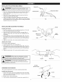
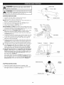
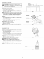
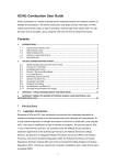
iNSTALLiNG
THE CUTTING
HEAD
SHIELD
Screws
operate the unitTowithout
cuttingpersonal
head shield
place.
WARNING:
preventthe
serious
injury,innever
_
1.
2,
3.
(2)
]
Mount Bracket
Place the cutting head shield onto the mount bracket. Align the
holes in the cutting head shield with the holes in the mount
bracket. (Fig. 1)
Screw the 2 screws through the mount bracket and into the
cutting head shield until finger tight.
"
Using a #2 Phillips screwdriver, tighten the screws until the
cutting head shield is firmly in place. Tighten the screws equally.
The gap between the mount bracket and the cutting head shield
should be the same on each side.
iNSTALLiNG AND ADJUSTING
hield
Fig. 1
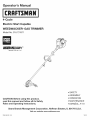
THE HANDLE
Handle
Installing
the Handle
1.
Push the handle down onto the shaft housing (Fig. 2). The bolt
hole in the handle should be to the right.
2. Insert the bolt into the bolt hole and push it through (Fig. 2).
Tighten the bolt with a 3/8" socket, but do not tighten the bolt
completely.
3. While holding the unit in the operating position (Fig. 13), move
the handle to the location that provides the best grip. Place it a
minimum of 6 inches (15.24 cm) from the end of the shaft grip
(Fig. 2).
4. Tighten the bolt with a 3/8" socket until the handle is secure.
Adjusting
Shaft Grip
Minimum 6 in.
(15.24 cm)
Shaft
Housing
Bolt J
Fig. 2
the Handle
If the handle requires adjustment:
1. Loosen the bolt with a 3/8" socket (Fig. 2).
2. While holding the unit in the operating position (Fig. 13), move
the handle to the location that provides the best grip. Place it a
minimum of 6 inches (15.24 cm) from the end of the shaft grip
(Fig. 2).
3. Tighten the bolt with a 3/8" socket until the handle is secure.
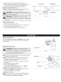
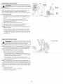
WARNING:
Before using any attachment,
read and
understand the manual that came with the attachment.
Follow all safety information contained within.
WARNING:
To avoid serious personal injury and
damage to the unit, shut the unit off before removing or
installing an attachment.
I
I
I
Coupler
Attachment
Fig. 3
I
90 ° Hole
(Trimmer
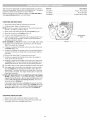
OPERATING
Only)
THE COUPLER
The coupler enables the use of various optional attachments.
Installing
the Attachment
Remove the hanger cap from the attachment. Keep the hanger
cap for use when storing the attachment. If present, remove the
gray spacer from the coupler.
2. Set the unit on a flat, level surface.
Loosen
1.
3. Turn the knob counterclockwise
Tighten
t
Knob
to loosen the coupler (Fig. 4).
Fig. 4
4. Align the release button with the guide recess (Fig. 5).
5. Push the attachment straight into the coupler (Fig. 3) until the
release button snaps firmly into the primary hole (Fig. 5).
6. Turn the knob clockwise to tighten the coupler (Fig. 4).
NOTE: Do not tighten the nut (Fig. 5).
NOTE: For decorative trimming with a string trimmer attachment,
lock the release button into the 90 ° hole (Fig. 4).
Primary Hole
Release Button
Guide Recess
CAUTION:
Before operating the unit, make sure the
release button is fully snapped into the primary hole and the
knob is securely tightened.
Nut
Fig. 5
CAUTION:
,_
Unless specified otherwise, the release
button should be snapped into the primary hole only. Using
the wrong hole could lead to personal injury or damage to
the unit.
Removing
the Attachment
1. Set the unit on a flat, level surface.
2. Turn the knob counterclockwise
to loosen the coupler (Fig. 4).
3.
4.
Press and hold the release button (Fig. 5).
Pull the attachment straight out of the coupler (Fig. 3).
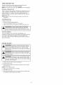
USING THE RIGHT OIL
Use a high-quality SAE 30 weight oil. DO NOT use dirty oil. Failure
to use clean oil of the correct type can cause premature engine
wear and failure.
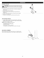
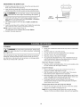
ADDING OIL: INITIAL USE
Funnel Spout _('_
WARNING:
OVERFILLING THE CRANKCASE MAY
CAUSE SERIOUS PERSONAL iNJURY. Check the oil level
before each use. The importance of maintaining the proper
oil level cannot be overemphasized. Change the oil
according to the Maintenance Schedule.
NOTE: This unit was shipped without oil in the crankcase. Oil must
be added before starting the unit.
NOTE: This unit comes with a 2.03 fluid oz. (60 ml) bottle of oil.
1. Unscrew the top of the oil bottle. Remove the paper seal.
Reinstall the top of the oil bottle.
2. Remove the cap from the oil bottle. Cut the tip off the funnel
spout (Fig. 6).
3. Set the unit on a fiat, level surface.
Unscrew the oil fill plug (Fig. 7).
Pour the entire bottle into the oil fill hole (Fig. 7). DO NOT
overfill. Refer to Checking the Off Level
NOTE: Never add oil directly to the fuel tank. This unit has a fourcycle engine. DO NOT mix oil with gasoline.
6. Wipe up any oil that may have spilled.
7. Reinstall the oil fill plug.
NOTE: Make sure the O-ring is in place on the oil fill plug (Fig. 7).
NOTE: Save the empty oil bottle. Use the bottle to measure the
correct amount of oil during future oil changes.
Fig. 6
O-Ring
4.
5.
Fig. 7
USING
THE
RIGHT
FUEL
The use of old fuel is the most common cause of performance
problems. Use only fresh, clean unleaded gasoline.
NOTE: This unit has a four-cycle engine. DO NOT mix oil with gasoline.
Definition of Blended Fuels
Today's fuels are often a blend of gasoline and oxygenates such as
ethanol, methanol or MTBE (ether). Alcohol-blended fuel absorbs
water. As little as 1% water in the fuel can make fuel and oil
separate, forming acids when stored. ALWAYS use fresh fuel (less
than 30 days old).
NOTE: Dispose of old fuel according to federal, state and local
regulations.
Using Blended Fuels
if using a blended fuel:
• Always use fresh unleaded gasoline
Use the fuel additive STA-BIL _ or an equivalent
Drain the tank and run the engine dry before storing the unit
!
I_
it has been proven that fuel containing greater than 10%
J
_WARNING:
DOdamage
NOT USE
FUEL
THiS
ethanol will likely
this E85
engine
andiNvoid
theUNIT.
warranty. |
Using Fuel Additives
Use a fuel additive, such as STA-BIL Fuel Stabilizer or an
equivalent, to inhibit corrosion and minimize gum deposits. Add 0.8
oz. (23 ml) of fuel additive per gallon of fuel, according to the
instructions on the container. NEVER add fuel additives directly to
the unit's fuel tank.
FUELING THE UNiT
I'1
WARNING:
Gasoline is extremely flammable, ignited
vapors may explode. Always stop the engine and allow it
to cool before filling the fuel tank. Do not smoke while
filling the tank. Keep sparks and open flames at a distance
from the area.
WARNING:
Remove the fuel cap slowly to avoid injury
from fuel spray. Never operate the unit without the fuel cap
securely in place.
I'1
WARNING:
Add fuel in a clean, well ventilated outdoor
area. Wipe up any spilled fuel immediately. Avoid creating
a source of ignition for spilled fuel. Do not start the engine
until fuel vapors dissipate.
1.
2.
3.
Position the unit with the fuel cap facing up.
Remove the fuel cap.
Place the fuel container spout into the fill hole on the fuel tank
and fill the tank.
NOTE: Do not overfill the tank.
4. Wipe up any fuel that may have spilled.
5. Reinstall the fuel cap.
6. Move the unit at least 30 ft. (9.1 m) from the fuel container and
the fueling site before starting the engine.
g
!
outdoor area. Carbon monoxide exhaust fumes can be
I_
I WARNING:
lethal in a confined
Operate
area.this unit only in a well-ventilated
[__J
serious injury, the operator and the unit must be in a stable
ARNING:
starting
position
when Avoid
pulling accidentally
the starter rope
(Fig.the
11).unit. To avoid
J
STARTING iNSTRUCTiONS
1.
Check the oil level. Refer to Checking the Oil Level.
Throttle Control
2. Fill the fuel tank. Refer to Fueling the Unit.
NOTE: There is no need to turn the unit on. The On/Off switch is in
the ON (I) position at all times (Fig. 8).
3. Slowly press and release the primer bulb 10 times (Fig. 9).
4. Move the choke lever to Position 1 (Fig. 10).
5. Crouch in the starting position (Fig. 11).
Fig. 8
NOTE: SQUEEZE and HOLD the throttle control for ALL further steps.
6. Squeeze the throttle control (Fig. 8) and pull the starter rope with
a controlled and steady motion 5 times (Fig. 11).
NOTE: This unit uses the INCREDI-PULL TM starting system, which
significantly reduces the effort required to start the engine.
7. Continue to squeeze the throttle control. Move the choke lever
to Position 2 (Fig. 10).
8. Continue to squeeze the throttle control. Pull the starter rope with
a controlled and steady motion 3 to 5 times to start the engine.
9. Continue to squeeze the throttle control. Allow the engine to
warm up for 30 to 60 seconds.
10. Continue to squeeze the throttle control. Move the choke lever
to Position 3 (Fig. 10) and continue warming the engine for an
additional 60 seconds. The unit may be used during this time.
\
Primer Bulb
Fig. 9
Position 3
iF... the engine does not start, begin the starting procedure with step 3.
iF... the engine fails to start after a few attempts, move the choke
lever to Position 3 and squeeze the throttle control. Pull the
starter rope with a controlled and steady motion 3 to 8 times.
The engine should start. If it does not, repeat this instruction.
IF THE UNiT WAS RUN FOR 10=15 MINUTES AND THE ENGINE
IS HOT... perform steps 3 - 8 to restart the engine. Continue to
squeeze the throttle control. Run the unit for 2-5 minutes, or as
needed. The unit may be used during this time. Then move
the choke lever to Position 3.
Fig. 10
Starting
Position
iNSTRUCTiONS
Starter
1.
2.
Position 1
Choke
Lever
If the engine speed fluctuates in Position 3, squeeze and hold
the throttle control, move the choke lever to Position 2, and run
the unit for 2-5 minutes, or as needed. The unit may be used
during this time. Then move the choke lever to Position 3.
STOPPING
Position 2
Rope Grip_
Release the throttle control and allow the engine to idle.
Press and hold the On/Off switch in the OFF (O) position until
the engine comes to a complete stop (Fig. 8).
Throttle
Fig. 11
10
Thisunitcanbestartedwithanoptional
SpeedStart
TM accessory
(items sold separately). Please refer to the Speed Start TM accessory
operator's manual for the proper use of this feature.
Please contact your local Craftsman retailer, call 1-800-469-4663 or
visit www.craftsman.com
for more information.
item No.
316.85951
316.85952
316.85953
Description
..............................
..................................
.............................
Plugqn Power Start
Power Bit Start
Cordless Power Start
STARTING iNSTRUCTiONS
1. Check the oil level. Refer to Checking the Oil Level.
2. Fill the fuel tank. Refer to Fueling the Unit.
NOTE: There is no need to turn the unit on. The On/Off switch is in
the ON (I) position at all times (Fig. 8).
3. Slowly press and release the primer bulb 10 times (Fig. 9).
4. Move the choke lever to Position 1 (Fig. 10).
5. Crouch in the starting position (Fig. 11).
6. insert the Speed Start TM accessory into the Speed Start TM port
(Fig. 12). Refer to the Operation section of the Speed Start TM
accessory operator's manual.
Speed Start
Port
Fig. 12
NOTE: SQUEEZE and HOLD the throttle control for ALL further steps.
7. Squeeze and hold the throttle control (Fig. 8). Run the Speed
Start TM accessory for 2 seconds.
8. Continue to squeeze the throttle control. Move the choke lever
to Position 2 (Fig. 10).
9. Continue to squeeze the throttle control. Run the Speed Start TM
accessory in intervals no longer than 2 seconds each until the
unit starts.
10. Remove the Speed Start TM accessory from the unit.
11. Continue to squeeze the throttle control. Allow the engine to
warm up for 30 to 60 seconds.
12. Continue to squeeze the throttle control. Move the choke lever
to Position 3 (Fig. 10) and continue warming the engine for an
additional 60 seconds. The unit may be used during this time.
iF... the engine does not start, begin the starting procedure with step 3.
iF... the engine fails to start after a few attempts, move the choke
lever to Position 3 and squeeze the throttle control. Run the
Speed Start TM accessory in intervals no longer than 2 seconds
each until the unit starts. The engine should start. If it does not,
repeat this instruction.
IF THE UNiT WAS RUN FOR 10-15 MINUTES AND THE ENGINE
iS HOT... perform steps 3 - 10 to restart the engine. Continue to
squeeze the throttle control. Run the unit for 2-5 minutes, or as
needed. The unit may be used during this time. Then move
the choke lever to Position 3.
If the engine speed fluctuates in Position 3, squeeze and hold
the throttle control, move the choke lever to Position 2, and run
the unit for 2=5 minutes, or as needed. The unit may be used
during this time. Then move the choke lever to Position 3.
STOPPING
1.
2.
INSTRUCTIONS
Release the throttle control and allow the engine to idle.
Press and hold the On/Off switch in the OFF (O) position until
the engine comes to a complete stop (Fig. 8).
11
TM
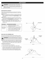
HOLDING THE UNiT
!
_
•
body protection to reduce the risk of injury when operating
Always wear eye, hearing, hand, foot and
WARNING:
this unit.
l
Stand in the operating position (Fig. 13). Stand up straight. Do
not bend over.
Keep feet apart and firmly planted.
Hold the shaft grip with the right hand. Keep the right arm
slightly bent.
Hold the handle with the left hand. Keep the left arm straight.
Hold the unit at waist level.
Fig. 13
Position the cutting head a few inches above the ground.
TIPS FOR BEST
RESULTS
=
To direct clippings away from the operator, tilt the cutting head
slightly down to the right; cut from left to right whenever possible.
Do not trim wet grass or weeds.
NOTE: Some line breakage will occur from:
Entanglement with foreign matter
Normal line fatigue
Attempting to cut thick vegetation
Forcing the line into objects such as walls or fence posts
DECORATIVE
TRiMMiNG
When trimming around trees, posts, fences, etc., rotate the whole
unit so that the cutting head is at a 30 ° angle to the ground (Fig. 14).
3
Fig. 14
12
WARNING:
To prevent serious injury, never perform
maintenance or repairs while the unit is running. Always
allow the unit to cool before servicing or repairing the unit.
Disconnect the spark plug wire to prevent the unit from
starting accidentally.
MAINTENANCE
SCHEDULE
Perform these required maintenance procedures at the frequency
stated in the table. These procedures should also be a part of any
seasonal tune-up.
NOTE: Some maintenance procedures may require special tools or
skills. If unsure about these procedures, take the unit to a Sears
or other qualified service dealer. Call 1-800-469-4663 for more
information.
NOTE: Maintenance, replacement, or repair of the emission control
devices and system may be performed by a Sears or other qualified
service dealer. Call 1-800-469-4663 for more information.
NOTE: Please read the California/EPA statement that came with the
unit for a complete listing of terms and coverage for the
emissions control devices, such as the spark arrestor, muffler,
carburetor, etc.
Cutting
Line
FREQUENCY
MAINTENANCE
Every 10 hours
•
Clean and re-oil the air filter. Refer to
Maintaining the Air Filter.
After the first
10 hours and
at 38 hours
•
Change the oil. Refer to Changing the Off.
Have the rocker arm clearance checked by
a Sears or other qualified service dealer.
Check the spark plug condition and gap.
Refer to Maintaining the Spark Plug.
Head
REQUIRED
Holes
Fig. 15
REPLACING THE TRIMMING
LINE
Only use the trimming line described in the Specifications section.
Other types of trimming line may cause the unit to overheat or fail.
Positioning
Tunnel
!
J
rope. These canNever
breakuse
off metal-reinforced
and become dangerous
_WARNING:
line, wire,projectiles.
chain or |
Positioning
Tunnel
NOTE: When using Craftsman® Hassle Free TM XTRA QUIET Spiral
Line, use the line best suited for the job at hand. Medium-sized (red)
line is designed for cutting grass and small weeds. Large-sized
(black) line is designed for cutting larger weeds and light brush.
Installing
1.
2.
New Trimming
Line
Line
Fig. 16
Remove the old line from the cutting head.
Use a clean cloth to clean the surface of the cutting head.
3.
Insert the ends of the line through the large circular holes in the
side of the cutting head (Fig. 15). Push the line through the holes
until both ends protrude from the positioning tunnels (Fig. 16).
4. Pull the ends of the line until the line is tight against the cutting
head. Make sure the ends of the line are of equal length (Fig. 17).
Line
Fig. 17
13
CHECKING THE OiL LEVEL
WARNING:
OVERFiLLiNG THE CRANKCASE MAY
CAUSE SERIOUS PERSONAL iNJURY. Check the oil level
before each use. The importance of maintaining the proper
oil level cannot be overemphasized.
inspecting
the Oil Level Window
1. Stop the engine and allow it to cool.
2. Set the unit on a flat, level surface, such as a workbench or
table. The cutting head shield should hang over the edge so that
the engine is level (Fig. 18).
NOTE: Failure to keep the engine level may cause the oil to overfill.
3. Look into the oil level window; use a flashlight if necessary. The
oil level should fill the window approximately
halfway (Fig.
19). If the oil level is too low, add oil. Refer to Adding Off.
Adding
Fig. 18
Oil Fifl Plu{
O=Ring
Oil
1.
Clean the area around the oil fill plug (Fig. 19) to prevent debris
from entering the oil fill hole.
2. Unscrew the oil fill plug.
3. Add oil to the oil fill hole until the oil level is approximately
halfway up the oil level window (Fig. 19).
NOTE: DO NOT overfill the crankcase.
Oil Fifl Hole
Maximum
Oil Level
4. Wipe up any oil that may have spilled.
5. Reinstall the oil fill plug.
NOTE: Make sure the O-ring is in place on the oil fill plug (Fig. 19).
CHANGING
Fig. 19
THE OiL
Change the oil while the engine is still warm. The oil will flow freely
and carry away more impurities.
1. Clean the area around the oil fill plug (Fig. 19) to prevent debris
from entering the oil fill hole.
2. Unscrew the oil fill plug.
3. Tip the unit vertically to pour the oil out of the oil fill hole and into
a container (Fig. 20). Allow ample time for complete drainage.
NOTE: Dispose of the old oil according to federal, state and local
regulations.
4. Wipe up any oil that may have spilled.
5. Pour 2.03 fl.oz. (60 ml) of SAE 30 oil into the oil fill hole.
NOTE: DO NOT overfill. Refer to Checking the Oil Level.
Fig. 20
NOTE: Use the empty oil bottle saved from the initial use to
measure the correct amount of oil. Fill the oil bottle to the 2.03 fl.
oz (60 ml) fill line indicated on the back of the bottle (Fig. 21).
6. Wipe up any oil that may have spilled.
7. Reinstall the oil fill plug.
NOTE: Make sure the O-ring is in place on the oil fill plug (Fig. 19).
Fig. 21
14
MAiNTAiNiNG
THE AiR FILTER
Hole
Air Filter
J
the engine and allow it to cool before cleaning or maintaining
WARNING;
To avoid serious personal injury, always stop |
the unit.
Air Filter
Cover
Failure to maintain the air filter can result in poor performance or can
cause permanent damage to the engine. Engine failure due to
improper air filter maintenance is not covered by the product warranty.
Cleaning
Tab
Cover
Screw
the Air Filter
Air Filter
1.
Unscrew the cover screw completely. Swing the air filter cover to
the right. Remove the air filter cover from the air filter housing
(Fig. 22).
2. Remove the air filter from the air filter housing (Fig. 22).
3. Wash the air filter in detergent and water. Rinse the air filter
thoroughly and allow it to dry.
4. Lightly coat the air filter with clean SAE 30 oil.
Fig. 22
5. Squeeze the air filter to spread and remove excess oil.
6. Reinstall the air filter in the air filter housing (Fig. 22).
NOTE: Operating the unit without the air filter and air filter cover will
VOiD the warranty.
7. insert the tab on the air filter cover into the hole on the air filter
housing. Swing the air filter cover to the left. Push the air filter
cover back onto the air filter housing, insert the cover screw into
the air filter cover. Tighten the cover screw to secure the air filter
cover (Fig. 22).
ADJUSTING THE iDLE SPEED
adjustments. Wear protective clothing and observe all
The cutting head may spin during idle speed I
safety nstruct ons to prevent ser ous persona njury,
j
WARNING:
NOTE: Careless adjustments can seriously damage the unit. A Sears or
other qualified service dealer should make carburetor adjustments.
if, after checking the fuel and cleaning the air filter, the engine still
will not idle, adjust the idle speed screw as follows:
1. Start the engine. Refer to Starting and Stopping.
2. Release the throttle control and let the engine idle.
Fig. 23
• if the engine stops, use a small Phillips screwdriver to turn the
idle speed screw clockwise, 1/8 of a turn at a time (as needed)
until the engine idles smoothly (Fig. 23).
if the engine idles too quickly, turn the idle speed screw
counterclockwise, 1/8 of a turn at a time (as needed) to reduce
the idle speed (Fig. 23).
NOTE: The cutting head should not spin when the engine idles, if it
does, reduce the idle speed until the cutting head stops moving.
Checking the fuel, cleaning the air filter, and adjusting the idle speed
should solve most engine problems, if not, and any of the following
conditions are true, take the unit to a Sears or other qualified service
dealer:
the engine will not idle
the engine hesitates or stalls on acceleration
there is a loss of engine power
15
MAiNTAiNiNG
THE SPARK PLUG
1.
Stop the engine and allow it to cool. Grasp the spark plug boot
firmly and pull it from the spark plug.
2. Clean around the spark plug. Remove the spark plug from the
cylinder head with a 5/8-inch socket, turning counterclockwise.
\
|
_
electrodes. GritDo
in not
the sand
engine
could
damage
the cylinder.
WARNING:
blast,
scrape
or clean
spark plug
J
0.025 in.
3.
inspect the spark plug. If the spark plug is cracked, fouled or
dirty, replace it with replacement part #753-05784, a Champion
RDZ4H or an equivalent spark plug.
4. Use a feeler gauge to set the air gap at 0.025 in. (0.635 ram)
(Fig. 24).
5. install the spark plug in the cylinder head. Tighten the spark plug
with a 5/8-inch socket, turning it clockwise until snug.
NOTE: If using a torque wrench, torque to:
110-120 in.,lb. (12.3-13.5 Nora). Do not over tighten.
6. Reattach the spark plug boot.
(0.635 ram}
Fig. 24
CLEANING
STORAGE
•
_
the engine and allow it to cool before cleaning or maintaining
To avoid serious personal injury, always stop
WARNING"
the unit.
t
J
Use a small brush to clean the outside of the unit. Do not use strong
detergents. Household cleaners that contain aromatic oils such as
pine and lemon, and solvents such as kerosene, can damage plastic.
Wipe off any moisture with a soft cloth.
•
•
•
•
•
Never store a fueled unit where fumes may reach an open flame
or spark.
Allow the engine to cool before storing.
Lock up the unit to prevent unauthorized use or damage.
Store the unit in a dry, well-ventilated area.
Store the unit out of the reach of children.
To suspend the attachment from a hook, install the hanger cap
onto the attachment. Make sure the release button is securely
locked into one of the holes on the hanger cap.
Short-term
Storage (1-2 weeks)
1. Store the unit in a horizontal position. If this is not possible, store
the unit vertically with the engine at the top.
Long-term
Storage
1. Remove the fuel cap, tip the unit and drain the fuel into an
approved container. Reinstall the fuel cap.
2. Start the engine and allow it to run until it stalls. This ensures
that all fuel has been drained from the carburetor.
3. Allow the engine to cool. Remove the spark plug and put 5 drops
of any high quality motor oil into the cylinder. Pull the starter rope
slowly to distribute the oil. Reinstall the spark plug.
4. Thoroughly clean the unit and inspect it for any loose or
damaged parts. Repair or replace damaged parts and tighten
loose screws, nuts or bolts.
Preparing the Unit for Use after Long=term
Storage
1. Remove the spark plug and drain all of the oil from the cylinder.
2. Change the oil. Refer to Changing the Off.
NOTE: Do not use fuel that has been stored for more than 30 days.
Dispose of old fuel according to federal, state and local regulations.
16
!
PROBLEM
SOLUTION
The primer bulb was not pressed enough
Press the primer bulb 10 times
The spark plug is fouled
Replace the spark plug
The fuel is old (over 30 days)
Drain the fuel tank and add fresh fuel
The fuel is old (over 30 days)
Drain the fuel tank and add fresh fuel
_tiho _ii
@u@_i
The air filter is dirty
Clean or replace the air filter
The fuel is old (over 30 days)
Drain the fuel tank and add fresh fuel
The spark plug is fouled
Replace the spark plug
HELP?
o Find this
and a[[ your other
_ Get answers
from our team
_ Get a personalized
_ Find information
product
manuals
of home
experts.
maintenance
plan
for your home.
and tools to help with
home projects.
fe
b[ought
online.
to you by Seals
.......
17
Congratulations on making a smart purchase. Your new Craftsman@ product is designed and manufactured for years of dependable
operation. But like all products, it may require repair from time to time. That's when having a Repair Protection Agreement can save you
money and aggravation.
Here's what the Repair Protection Agreement*
includes:
[]
Expert service
[]
[]
[]
Unlimited service and no charge for parts and labor on all covered repairs
Product replacement up to $1500 if your covered product can't be fixed
Discount of 25% from regular price of service and related installed parts not covered by the agreement; also, 25% off regular price of
preventive maintenance check
Fast help by phone - we call it Rapid Resolution - phone support from a Sears representative. Think of us as a "talking owner's manual."
[]
by our 10,000 professional repair specialists
Once you purchase the Repair Protection Agreement, a simple phone call is all that it takes for you to schedule service. You can call anytime
day or night, or schedule a service appointment online.
The Repair Protection Agreement is a risk-free purchase. If you cancel for any reason during the product warranty period, we will provide a
full refund. Or, a prorated refund anytime after the product warranty period expires. Purchase your Repair Protection Agreement today!
Some limitations and exclusions apply. For prices and additional information in the U.S.A. call 1-800-827-6655.
*Coverage in Canada varies on some items. For full details call Sears Canada at 1-800-361-6665.
Sears Installation Service
For Sears professional instaflation of home appliances,
Canada call 1-800-4-MY-HOME.
garage door openers, water heaters, and other major home items, in the U.S.A. or
18
For troubleshooting,
Your Home
product manuals and expert advice:
managemylife
www.managemylife.com
For repair - in your home - of all major brand appliances,
lawn and garden equipment, or heating and cooling systems,
no matter who made it, no matter who sold it!
For the replacement parts, accessories and
owner's manuals that you need to do-it-yourself.
For Sears professional installation of home appliances
and items like garage door openers and water heaters.
1=800=4=MY=HOME®
Call anytime,
day or night
(U.S.A. and Canada)
(1 =800=469=4663)
www.sears.corn
www.sears.ca
Our Home
For repair of carry-in items like vacuums, lawn equipment,
and electronics, call anytime for the location of the nearest
Sears Parts & Repair Service
1-800-488-1222
(U.S.A.)
1-800-46g-4663
www.sears.com
agreement
(U.S.A.)
Para pedir servicio de reparaci6n
a domicilio, y para ordenar piezas:
1-888-SU-HOGAR
(1-888-784-6427)
www.sears.com
(Canada)
www.sears.ca
To purchase a protection
1-800-827-6655
Center
on a product serviced
by Sears:
1=800-361-6665
(Canada)
Au Canada pour service
en fran(_ais:
®
1=800=LE=FOYER Mc
(1-800-533-6937
www.sears.ca
soars
® Registered Trademark / TM Trademark of KCD IP, LLC in the United States, or Sears Brands, LLC in other countries
® Marca Registrada / TM Marca de F&brica de KCD IP, LLC en Estados Unidos, o Sears Brands, LLC in otros paises
MCMarque de commerce / MDMarque d6pos6e de Sears Brands, LLC