1
Watson SHDSL Router
Web-based Management Manual
Document Identification
Document Version
Document Revision
Distribution
Watson-SHDSL-Router-GUI-Manual.doc
2.3-03
2012-02-29
Customer
Revision History
Revision
Date
Author
Remarks
2.3.03
2.3-02
2.3-01
2.2-03
2.2-02
2.2-01
120229
100819
100111
091110
091109
090907
MHb
MLr
MLr
MLr
MLr
MLr
2.1-01
2.0-01
1.0-01
090406 MLr
080616 MLr
070615 MLr
Minor Update for TC-PAM 64/128
Updated software license notice
Added port-based VLAN stacking
Minor Updates
Added ALG Rules configuration
Added Stacked VLAN configuration
Added hierarchical QoS configuration
Updated Manual for SW Release 4.11.2
Updated Manual for SW Release 4.9.2
First version
Copyright 2012 by Schmid Telecommunication, Zurich, Switzerland. All rights reserved. Reproduction of part or
all of the contents in any form is expressly prohibited without the prior written consent of Schmid Telecommunication.
Schmid Telecommunication has used its discretion, best judgments and efforts in preparing this document. Any
information contained in this document is provided without any warranty of any kind. Schmid Telecommunication
hereby disclaims any liability to any person for any kind of damage. Schmid Telecommunication may make improvements and/or changes of this document at any time.
Table of Contents
Table of Contents ..................................................................................................................................... 1-1
1
Related Documents .......................................................................................................................... 1-1
2
Overview ........................................................................................................................................... 2-1
2.1 Introduction .............................................................................................................................. 2-1
3
Getting Started ................................................................................................................................. 3-1
3.1 Introduction .............................................................................................................................. 3-1
3.2 LAN and DSL Connections ...................................................................................................... 3-1
3.3 PC Network Configuration........................................................................................................ 3-1
3.3.1
Windows XP ........................................................................................................... 3-2
3.3.2
Windows 2000/98/Me............................................................................................. 3-2
3.3.3
Linux ....................................................................................................................... 3-3
3.4 Watson Configuration .............................................................................................................. 3-3
3.4.1
Configuring your DSL connection........................................................................... 3-4
3.4.2
Configuring Your Internet Connection .................................................................... 3-4
4
Using the Web-based Management ................................................................................................ 4-1
4.1 Accessing the Web-based Management ................................................................................. 4-1
4.2 Navigational Aids...................................................................................................................... 4-2
4.3 Managing Tables ...................................................................................................................... 4-3
5
Home.................................................................................................................................................. 5-1
5.1 Overview .................................................................................................................................. 5-1
5.2 Map View.................................................................................................................................. 5-2
5.3 Installation Wizard .................................................................................................................... 5-2
5.3.1
Step 1: Analyze Internet Connection Type ............................................................. 5-3
5.3.2
Step 2: Setup Internet Connection ......................................................................... 5-4
5.3.3
Step 3: Test Service Provider Connection ............................................................. 5-4
5.3.4
Step 4: Test Internet Connection ........................................................................... 5-4
5.3.5
Step 5: Installation Completed ............................................................................... 5-4
5.4 Quick Setup.............................................................................................................................. 5-4
5.4.1
Configuring Your Internet Connection .................................................................... 5-5
5.4.2
Quick Setup Completed ......................................................................................... 5-8
6
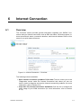
Internet Connection ......................................................................................................................... 6-1
6.1 Overview .................................................................................................................................. 6-1
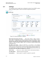
6.2 Settings .................................................................................................................................... 6-2
6.3 Diagnostics ............................................................................................................................... 6-4
6.4 SHDSL Status .......................................................................................................................... 6-5
7
Local Network ................................................................................................................................... 7-1
7.1 Overview .................................................................................................................................. 7-1
7.2 Device View.............................................................................................................................. 7-3
8
Services ............................................................................................................................................. 8-1
8.1 Overview .................................................................................................................................. 8-1
8.2 Firewall ..................................................................................................................................... 8-1
8.2.1
Overview ................................................................................................................ 8-2
8.2.2
Access Control ....................................................................................................... 8-3
Revision: 2012-02-29
1-1
Watson SHDSL Router
Web-based Management Manual
8.3
8.4
8.5
8.6
9
1-2
Watson-SHDSL-Router-GUI-Manual.doc
Version 2.3-03
8.2.3
Port Forwarding ...................................................................................................... 8-6
8.2.4
DMZ Host ............................................................................................................. 8-10
8.2.5
Port Triggering ..................................................................................................... 8-11
8.2.6
Website Restrictions ............................................................................................ 8-13
8.2.7
Network Address Translation (NAT) .................................................................... 8-14
8.2.8
Connections ......................................................................................................... 8-22
8.2.9
Advanced Filtering................................................................................................ 8-23
8.2.10
Log ....................................................................................................................... 8-28
8.2.11
Applying Corporate-Grade Security ..................................................................... 8-33
Quality of Service ................................................................................................................... 8-34
8.3.1
Overview .............................................................................................................. 8-35
8.3.2
Internet Connection Utilization ............................................................................. 8-37
8.3.3
Traffic Priority ....................................................................................................... 8-39
8.3.4
Traffic Shaping ..................................................................................................... 8-44
8.3.5
Differentiated Services Code Point Settings ........................................................ 8-50
8.3.6
802.1p Settings .................................................................................................... 8-52
8.3.7
Class Statistics ..................................................................................................... 8-53
Virtual Private Network ........................................................................................................... 8-53
8.4.1
Internet Protocol Security ..................................................................................... 8-53
8.4.2
Point-to-Point Tunneling Protocol Server ............................................................. 8-90
Personal Domain Name (Dynamic DNS) ............................................................................... 8-92
8.5.1
Opening a Dynamic DNS Account ....................................................................... 8-92
8.5.2
Using Dynamic DNS ............................................................................................ 8-92
Advanced ............................................................................................................................... 8-94
8.6.1
DNS Server .......................................................................................................... 8-94
8.6.2
IP Address Distribution ......................................................................................... 8-95
System ............................................................................................................................................... 9-1
9.1 Overview .................................................................................................................................. 9-1
9.2 Settings .................................................................................................................................... 9-1
9.2.1
Overview ................................................................................................................ 9-1
9.2.2
Date and Time........................................................................................................ 9-5
9.3 Users ........................................................................................................................................ 9-9
9.3.1
User Settings ........................................................................................................ 9-10
9.3.2
Group Settings ..................................................................................................... 9-11
9.4 Network Connections ............................................................................................................. 9-12
9.4.1
The Connection Wizard ....................................................................................... 9-13
9.4.2
Network Types ..................................................................................................... 9-17
9.4.3
WAN Ethernet ...................................................................................................... 9-17
9.4.4
LAN Switch ........................................................................................................... 9-24
9.4.5
LAN Ethernet ........................................................................................................ 9-33
9.4.6
DSL ...................................................................................................................... 9-34
9.4.7
Dynamic Host Configuration Protocol (DHCP)..................................................... 9-36
9.4.8
Manual IP Address Configuration ........................................................................ 9-38
9.4.9
Point-to-Point Protocol over Ethernet (PPPoE) .................................................... 9-40
9.4.10
Network Bridging .................................................................................................. 9-48
9.4.11
Virtual LAN Interface (VLAN) ............................................................................... 9-65
9.4.12
Point-to-Point Tunneling Protocol (PPTP) ............................................................ 9-70
9.4.13
Point-to-Point Tunneling Protocol Server (PPTP Server) .................................... 9-79
9.4.14
Internet Protocol Security (IPSec) ........................................................................ 9-81
9.4.15
Internet Protocol Security Server (IPSec Server) ................................................. 9-83
9.4.16
Internet Protocol over Internet Protocol (IPIP) ..................................................... 9-85
9.4.17
General Routing Encapsulation (GRE) ................................................................ 9-90
9.5 Monitor ................................................................................................................................... 9-95
9.5.1
Network ................................................................................................................ 9-95
Revision: 2012-02-29
Watson-SHDSL-Router-GUI-Manual.doc
Version 2.3-03
9.6
9.7
9.8
9.9
Watson SHDSL Router
Web-based Management Manual
9.5.2
CPU ...................................................................................................................... 9-95
9.5.3
Log ....................................................................................................................... 9-97
Routing ................................................................................................................................... 9-99
9.6.1
Overview .............................................................................................................. 9-99
9.6.2
BGP and OSPF .................................................................................................. 9-100
9.6.3
PPPoE Relay...................................................................................................... 9-103
Management ........................................................................................................................ 9-103
9.7.1
Universal Plug and Play ..................................................................................... 9-103
9.7.2
Simple Network Management Protocol .............................................................. 9-106
9.7.3
Remote Administration ....................................................................................... 9-110
9.7.4
Secure Shell ....................................................................................................... 9-113
Maintenance ......................................................................................................................... 9-114
9.8.1
About Watson .................................................................................................... 9-114
9.8.2
Configuration File ............................................................................................... 9-114
9.8.3
Reboot ................................................................................................................ 9-115
9.8.4
Restore Factory MAC Address .......................................................................... 9-116
9.8.5
Restore Defaults ................................................................................................ 9-116
9.8.6
Watson Firmware Upgrade .................................................................................... 9-1
9.8.7
MAC Cloning .......................................................................................................... 9-2
9.8.8
Diagnostics ............................................................................................................. 9-3
Objects and Rules .................................................................................................................... 9-5
9.9.1
Protocols ................................................................................................................ 9-5
9.9.2
Network Objects ..................................................................................................... 9-6
9.9.3
Scheduler Rules ..................................................................................................... 9-8
9.9.4
Certificates ........................................................................................................... 9-10
10
Advanced ........................................................................................................................................ 10-1
11
Appendix ......................................................................................................................................... 11-4
11.1 List of Acronyms ..................................................................................................................... 11-4
11.2 Glossary ................................................................................................................................. 11-6
11.3 Licensing Acknowledgement and Source Code Offering .................................................... 11-12
Figures
Figure 3-1: IP and DNS Configuration ................................................................................................ 3-2
Figure 3-2: Internet Connection – DSL Settings ................................................................................. 3-4
Figure 3-3: Quick Setup ..................................................................................................................... 3-5
Figure 4-1: Web-based Management Login ....................................................................................... 4-1
Figure 4-2: Navigation Components ................................................................................................... 4-2
Figure 4-3: Constant Link Bar ............................................................................................................ 4-2
Figure 4-4: Typical Table Structure .................................................................................................... 4-3
Figure 5-1: Watson Overview ............................................................................................................. 5-1
Figure 5-2: The Network Map............................................................................................................. 5-2
Figure 5-3: Installation Wizard ............................................................................................................ 5-3
Figure 5-4: Test Internet Connection.................................................................................................. 5-3
Figure 5-5: Test Internet Connection – Failure................................................................................... 5-4
Figure 5-6: Quick Setup ..................................................................................................................... 5-5
Figure 5-7: WAN Ethernet Properties ................................................................................................ 5-6
Figure 5-8: Internet Connection - Manual IP Address Ethernet Connection ...................................... 5-6
Figure 5-9: Internet Connection - Automatic IP Address Ethernet Connection .................................. 5-7
Figure 5-10: Internet Connection - PPTP ........................................................................................... 5-7
Figure 5-11: PPTP - Static IP Address ............................................................................................... 5-8
Figure 5-12: Internet Connection - PPPoE ......................................................................................... 5-8
Revision: 2012-02-29
1-3
Watson SHDSL Router
Web-based Management Manual
Watson-SHDSL-Router-GUI-Manual.doc
Version 2.3-03
Figure 5-13: Internet Connection - No Internet Connection ............................................................... 5-8
Figure 6-1: Internet Connection – Overview ....................................................................................... 6-1
Figure 6-2: Internet Connection – Settings ......................................................................................... 6-2
Figure 6-3: WAN Ethernet Properties ................................................................................................ 6-3
Figure 6-4: Internet Connection – Diagnostics ................................................................................... 6-4
Figure 6-5: Diagnostics Process ........................................................................................................ 6-4
Figure 6-6: Internet Connection – SHDSL Status .............................................................................. 6-5
Figure 7-1: Local Network Overview .................................................................................................. 7-1
Figure 7-2: Host Information............................................................................................................... 7-2
Figure 7-3: Local Network Device View.............................................................................................. 7-3
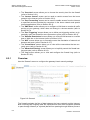
Figure 8-1: Services Overview ........................................................................................................... 8-1
Figure 8-2: General ............................................................................................................................ 8-2
Figure 8-3: Access Control ................................................................................................................. 8-4
Figure 8-4: Add Access Control Rule ................................................................................................. 8-4
Figure 8-5: Access Control Rule ........................................................................................................ 8-5
Figure 8-6: Edit Access Control Rule ................................................................................................. 8-5
Figure 8-7: Port Forwarding................................................................................................................ 8-7
Figure 8-8: Add Port Forwarding Rule ................................................................................................ 8-8
Figure 8-9: Specify Public IP Address ................................................................................................ 8-8
Figure 8-10: Forward to a Specific Port .............................................................................................. 8-8
Figure 8-11: Port Forwarding Rule ..................................................................................................... 8-9
Figure 8-12: Allow Incoming WAN Access to Web-Management .................................................... 8-10
Figure 8-13: DMZ Host ..................................................................................................................... 8-11
Figure 8-14: Port Triggering ............................................................................................................. 8-12
Figure 8-15: New Port Triggering Rule ............................................................................................. 8-12
Figure 8-16: Website Restrictions .................................................................................................... 8-13
Figure 8-17: Network Address Translation ....................................................................................... 8-15
Figure 8-18: Edit Item ....................................................................................................................... 8-15
Figure 8-19: Add NAT/NAPT Rule ................................................................................................... 8-16
Figure 8-20: NAT IP Addresses ....................................................................................................... 8-18
Figure 8-21: NAT/NAPT Rule Sets ................................................................................................... 8-19
Figure 8-22: NAT/NAPT Rule Sets................................................................................................... 8-19
Figure 8-23: Attention ....................................................................................................................... 8-20
Figure 8-24: NAT/NAPT Rule Sets ................................................................................................... 8-20
Figure 8-25: Add NAPT Rule ............................................................................................................ 8-21
Figure 8-26: NAT/NAPT Rule Sets ................................................................................................... 8-21
Figure 8-27: NAT/NAPT Rule Sets ................................................................................................... 8-22
Figure 8-28: Connection List ............................................................................................................ 8-23
Figure 8-29: Advanced Filtering ....................................................................................................... 8-24
Figure 8-30: Move Up and Move Down Action Icons ....................................................................... 8-25
Figure 8-31: Add Advanced Filter ..................................................................................................... 8-25
Figure 8-32: Add ALG Rule .............................................................................................................. 8-27
Figure 8-33: Firewall Log .................................................................................................................. 8-28
Figure 8-34: Log Settings ................................................................................................................ 8-30
Figure 8-35: Enabling Secure Remote Administration ..................................................................... 8-34
Figure 8-36: Apply Firewall Protection .............................................................................................. 8-34
Figure 8-37: General ........................................................................................................................ 8-36
Figure 8-38: Internet Connection Utilization by Application .............................................................. 8-38
Figure 8-39: A Specific Application................................................................................................... 8-38
Figure 8-40: Internet Connection Utilization by Computer ................................................................ 8-39
Figure 8-41: Traffic Priority ............................................................................................................... 8-41
1-4
Revision: 2012-02-29
Watson-SHDSL-Router-GUI-Manual.doc
Version 2.3-03
Watson SHDSL Router
Web-based Management Manual
Figure 8-42: Add Traffic Priority Rule ............................................................................................... 8-42
Figure 8-43: Set DSCP Rule ............................................................................................................ 8-43
Figure 8-44: Set Priority with Queueing ............................................................................................ 8-43
Figure 8-45: Traffic Shaping ............................................................................................................. 8-45
Figure 8-46: Edit Device Traffic Shaping .......................................................................................... 8-46
Figure 8-47: TCP Serialization – Maximum Delay............................................................................ 8-47
Figure 8-48: Add Shaping Class....................................................................................................... 8-47
Figure 8-49: Edit Shaping Class ....................................................................................................... 8-48
Figure 8-50: Specify Maximum Bandwidth ....................................................................................... 8-48
Figure 8-51: Hierarchical Tocken Bucket ......................................................................................... 8-49
Figure 8-52: Add Policing Class ....................................................................................................... 8-50
Figure 8-53: Edit Policing Class ....................................................................................................... 8-50
Figure 8-54: Specify Maximum Bandwidth ....................................................................................... 8-50
Figure 8-55: DSCP–Traffic Priority Matching ................................................................................... 8-51
Figure 8-56: Edit DSCP Settings ...................................................................................................... 8-52
Figure 8-57: Traffic Queuing in 802.1p Settings............................................................................... 8-52
Figure 8-58: Class Statistics ............................................................................................................. 8-53
Figure 8-59: Internet Protocol Security (IPSec) ................................................................................ 8-54
Figure 8-60: Internet Protocol Security (IPSec) Settings .................................................................. 8-55
Figure 8-61: IPSec Log Settings....................................................................................................... 8-56
Figure 8-62: VPN IPSec Properties – General ................................................................................. 8-57
Figure 8-63: VPN IPSec Properties – Settings ................................................................................. 8-57
Figure 8-64: VPN IPSec Properties – Routing ................................................................................. 8-58
Figure 8-65: VPN IPSec Properties – IPSec .................................................................................... 8-58
Figure 8-66: Automatic Key Exchange Settings ............................................................................... 8-61
Figure 8-67: Manual Key Definition .................................................................................................. 8-63
Figure 8-68: Network Connections ................................................................................................... 8-64
Figure 8-69: Connection Wizard....................................................................................................... 8-64
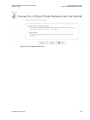
Figure 8-70: Connect to a Virtual Private Network over the Internet ................................................ 8-65
Figure 8-71: VPN Client or Point-To-Point ....................................................................................... 8-65
Figure 8-72: Internet Protocol Security (IPSec) ................................................................................ 8-66
Figure 8-73: Connection Summary .................................................................................................. 8-66
Figure 8-74: New VPN IPSec Connection ........................................................................................ 8-67
Figure 8-75: Local Security Settings ................................................................................................. 8-67
Figure 8-76: IP Security Policy Wizard ............................................................................................. 8-68
Figure 8-77: IP Security Policy Name ............................................................................................... 8-68
Figure 8-78: Requests for Secure Communication .......................................................................... 8-69
Figure 8-79: Completing the IP Security Policy Wizard .................................................................... 8-69
Figure 8-80: Watson Connection Properties .................................................................................... 8-70
Figure 8-81: New Rule Properties .................................................................................................... 8-70
Figure 8-82: IP Filter List .................................................................................................................. 8-71
Figure 8-83: Filter Properties ............................................................................................................ 8-71
Figure 8-84: Windows XP to Watson Filter Properties ..................................................................... 8-72
Figure 8-85: IP Filter List .................................................................................................................. 8-73
Figure 8-86: Filter Action .................................................................................................................. 8-73
Figure 8-87: Require Security Properties ......................................................................................... 8-74
Figure 8-88: Edit Authentication Method Properties ......................................................................... 8-74
Figure 8-89: Tunnel Setting .............................................................................................................. 8-75
Figure 8-90: IP Filter List .................................................................................................................. 8-75
Figure 8-91: Tunnel Setting .............................................................................................................. 8-76
Figure 8-92: Watson Connection Properties .................................................................................... 8-76
Revision: 2012-02-29
1-5
Watson SHDSL Router
Web-based Management Manual
Watson-SHDSL-Router-GUI-Manual.doc
Version 2.3-03
Figure 8-93: Local Security Settings ................................................................................................. 8-77
Figure 8-94: Configuration Diagram ................................................................................................. 8-77
Figure 8-95: Network Connections ................................................................................................... 8-78
Figure 8-96: LAN Switch Properties – General ................................................................................ 8-79
Figure 8-97: LAN Switch Properties – Settings ................................................................................ 8-79
Figure 8-98: Network Connections ................................................................................................... 8-80
Figure 8-99: WAN Ethernet Properties – General ............................................................................ 8-81
Figure 8-100: WAN Ethernet Properties – Settings ......................................................................... 8-81
Figure 8-101: Network Connections ................................................................................................. 8-83
Figure 8-102: Connection Wizard..................................................................................................... 8-83
Figure 8-103: Connect to a Virtual Private Network over the Internet .............................................. 8-84
Figure 8-104: VPN Client or Point-To-Point ..................................................................................... 8-84
Figure 8-105: Internet Protocol Security (IPSec) .............................................................................. 8-85
Figure 8-106: Internet Protocol Security (IPSec) .............................................................................. 8-85
Figure 8-107: Connection Summary ................................................................................................ 8-86
Figure 8-108: Load CA's Certificate ................................................................................................. 8-87
Figure 8-109: Create X509 Request ................................................................................................ 8-88
Figure 8-110: New X509 Request .................................................................................................... 8-88
Figure 8-111: Load Watson's Local Certificate ................................................................................ 8-89
Figure 8-112: VPN IPSec Properties ................................................................................................ 8-89
Figure 8-113: Point-to-Point Tunneling Protocol Server (PPTP Server) .......................................... 8-90
Figure 8-114: Advanced PPTP Server Parameters ......................................................................... 8-91
Figure 8-115: Dynamic DNS............................................................................................................. 8-92
Figure 8-116: Dynamic DNS............................................................................................................. 8-93
Figure 8-117: SSL Mode .................................................................................................................. 8-94
Figure 8-118: DNS Table ................................................................................................................. 8-95
Figure 8-119: IP Address Distribution .............................................................................................. 8-96
Figure 8-120: DHCP Server Settings for LAN Switch ...................................................................... 8-97
Figure 8-121: DHCP Relay Settings for LAN Switch ........................................................................ 8-98
Figure 8-122: DHCP Relay Server Address ..................................................................................... 8-98
Figure 8-123: Configure WAN Ethernet – Routing ........................................................................... 8-99
Figure 8-124: DHCP Connections .................................................................................................... 8-99
Figure 8-125: DHCP Connection Settings ...................................................................................... 8-100
Figure 9-1: System Monitoring Overview ........................................................................................... 9-1
Figure 9-2: System Settings ............................................................................................................... 9-2
Figure 9-3: System Settings ............................................................................................................... 9-4
Figure 9-4: Date and Time Settings ................................................................................................... 9-6
Figure 9-5: Windows–Date and Time Properties ............................................................................... 9-7
Figure 9-6: Windows–Internet Time Screen....................................................................................... 9-8
Figure 9-7: Users ................................................................................................................................ 9-9
Figure 9-8: User Settings ................................................................................................................. 9-10
Figure 9-9: Group Settings ............................................................................................................... 9-11
Figure 9-10: Network Connections - Basic ....................................................................................... 9-12
Figure 9-11: Network Connections - Advanced................................................................................ 9-12
Figure 9-12: Connection Wizard....................................................................................................... 9-14
Figure 9-13: Internet Connection Wizard Screen ............................................................................. 9-14
Figure 9-14: VPN Wizard Screen ..................................................................................................... 9-15
Figure 9-15: Advanced Connection Wizard Screen ......................................................................... 9-16
Figure 9-16: WAN Ethernet Properties – General ............................................................................ 9-18
Figure 9-17: WAN Ethernet Properties - Settings ............................................................................ 9-18
Figure 9-18: Internet Protocol – No IP Address ............................................................................... 9-19
1-6
Revision: 2012-02-29
Watson-SHDSL-Router-GUI-Manual.doc
Version 2.3-03
Watson SHDSL Router
Web-based Management Manual
Figure 9-19: Internet Protocol Settings – Automatic IP .................................................................... 9-19
Figure 9-20: Internet Protocol – Static IP ......................................................................................... 9-20
Figure 9-21: DNS Server – Automatic IP ......................................................................................... 9-20
Figure 9-22: DNS Server – Static IP................................................................................................. 9-20
Figure 9-23: IP Address Distribution - DHCP Server ....................................................................... 9-21
Figure 9-24: IP Address Distribution - DHCP Relay ......................................................................... 9-21
Figure 9-25: DHCP Relay Server Address ....................................................................................... 9-22
Figure 9-26: IP Address Distribution - Disable DHCP ...................................................................... 9-22
Figure 9-27: Advanced Routing Properties ...................................................................................... 9-23
Figure 9-28: Internet Connection Firewall ........................................................................................ 9-23
Figure 9-29: Additional IP Addresses ............................................................................................... 9-23
Figure 9-30: LAN Switch Properties – General ................................................................................ 9-24
Figure 9-31: LAN Switch Properties - Settings ................................................................................. 9-25
Figure 9-32: Internet Protocol – No IP Address ............................................................................... 9-25
Figure 9-33: Internet Protocol Settings – Automatic IP .................................................................... 9-25
Figure 9-34: Internet Protocol – Static IP ......................................................................................... 9-26
Figure 9-35: DNS Server – Automatic IP ......................................................................................... 9-26
Figure 9-36: DNS Server – Static IP................................................................................................. 9-26
Figure 9-37: IP Address Distribution – DHCP Server ....................................................................... 9-27
Figure 9-38: IP Address Distribution – DHCP Relay ........................................................................ 9-27
Figure 9-39: DHCP Relay Server Address ....................................................................................... 9-28
Figure 9-40: IP Address Distribution - Disable DHCP ...................................................................... 9-28
Figure 9-41: Advanced Routing Properties ...................................................................................... 9-29
Figure 9-42: Switch VLAN ................................................................................................................ 9-30
Figure 9-43: Add Switch VLAN ......................................................................................................... 9-31
Figure 9-44: VLAN Example ............................................................................................................. 9-32
Figure 9-45: Internet Connection Firewall ........................................................................................ 9-32
Figure 9-46: Additional IP Addresses ............................................................................................... 9-33
Figure 9-47: LAN Ethernet Properties .............................................................................................. 9-33
Figure 9-48: DSL Configuration ........................................................................................................ 9-35
Figure 9-49: DSL Status ................................................................................................................... 9-36
Figure 9-50: Ethernet Connection .................................................................................................... 9-37
Figure 9-51: Connection Summary .................................................................................................. 9-37
Figure 9-52: Ethernet Connection .................................................................................................... 9-38
Figure 9-53: Manual IP Address Configuration ................................................................................ 9-39
Figure 9-54: Connection Summary .................................................................................................. 9-39
Figure 9-55: Point-to-Point Protocol over Ethernet........................................................................... 9-40
Figure 9-56: Connection Summary .................................................................................................. 9-41
Figure 9-57: WAN PPPoE Properties............................................................................................... 9-42
Figure 9-58: PPPoE Settings............................................................................................................ 9-42
Figure 9-59: Internet Protocol – Unnumbered .................................................................................. 9-43
Figure 9-60: Internet Protocol – Automatic IP .................................................................................. 9-43
Figure 9-61: Internet Protocol – Static IP ......................................................................................... 9-44
Figure 9-62: DNS Server – Automatic IP ......................................................................................... 9-44
Figure 9-63: DNS Server – Static IP................................................................................................. 9-44
Figure 9-64: Advanced Routing Properties ...................................................................................... 9-45
Figure 9-65: PPP Configuration........................................................................................................ 9-46
Figure 9-66: PPP Authentication ...................................................................................................... 9-46
Figure 9-67: PPP Encryption ............................................................................................................ 9-47
Figure 9-68: PPP Compression........................................................................................................ 9-47
Figure 9-69: Internet Connection Firewall ........................................................................................ 9-48
Revision: 2012-02-29
1-7
Watson SHDSL Router
Web-based Management Manual
Watson-SHDSL-Router-GUI-Manual.doc
Version 2.3-03
Figure 9-70: Network Bridging .......................................................................................................... 9-48
Figure 9-71: Connection Summary – Network Bridging ................................................................... 9-49
Figure 9-72: Bridge Properties ......................................................................................................... 9-50
Figure 9-73: Bridge Routing Settings ............................................................................................... 9-51
Figure 9-74: Browser Reload Warning Message ............................................................................. 9-51
Figure 9-75: WAN-LAN Bridging Settings ........................................................................................ 9-52
Figure 9-76: Bridge Filter Settings .................................................................................................... 9-52
Figure 9-77: Edit Network Object ..................................................................................................... 9-53
Figure 9-78: Edit Item – MAC Address ............................................................................................. 9-53
Figure 9-79: Edit Item – DHCP Options ........................................................................................... 9-54
Figure 9-80: Bridge Properties ......................................................................................................... 9-55
Figure 9-81: Bridge Settings ............................................................................................................. 9-55
Figure 9-82: Internet Protocol – No IP Address ............................................................................... 9-56
Figure 9-83: Internet Protocol – Automatic IP .................................................................................. 9-57
Figure 9-84: Internet Protocol – Static IP ......................................................................................... 9-57
Figure 9-85: DNS Server – Automatic IP ......................................................................................... 9-57
Figure 9-86: DNS Server – Static IP................................................................................................. 9-58
Figure 9-87: IP Address Distribution – DHCP Server ....................................................................... 9-59
Figure 9-88: IP Address Distribution - DHCP Relay ......................................................................... 9-59
Figure 9-89: DHCP Relay Server Address ....................................................................................... 9-59
Figure 9-90: IP Address Distribution - Disable DHCP ...................................................................... 9-60
Figure 9-91: Advanced Routing Properties ...................................................................................... 9-61
Figure 9-92: Bridge Settings ............................................................................................................. 9-61
Figure 9-93: Transparent Mode ........................................................................................................ 9-62
Figure 9-94: Stacked VLAN Mode .................................................................................................... 9-63
Figure 9-95: Rule Settings ................................................................................................................ 9-63
Figure 9-96: Port Based Mode ......................................................................................................... 9-64
Figure 9-97: Internet Connection Firewall ........................................................................................ 9-65
Figure 9-98: Additional IP Addresses ............................................................................................... 9-65
Figure 9-99: VLAN Interface ............................................................................................................. 9-66
Figure 9-100: Connection Summary ................................................................................................ 9-66
Figure 9-101: VLAN Interface Properties ......................................................................................... 9-67
Figure 9-102: VLAN Interface Settings ............................................................................................ 9-67
Figure 9-103: Internet Protocol – No IP Address ............................................................................. 9-68
Figure 9-104: Internet Protocol – Automatic IP ................................................................................ 9-68
Figure 9-105: Internet Protocol – Static IP ....................................................................................... 9-69
Figure 9-106: Internet Connection Firewall ...................................................................................... 9-69
Figure 9-107: Additional IP Addresses ............................................................................................. 9-69
Figure 9-108: DSCP Remark According to 802.1p CoS .................................................................. 9-69
Figure 9-109: DSCP Remarks Table ............................................................................................... 9-70
Figure 9-110: DSCP Remark Entry Settings .................................................................................... 9-70
Figure 9-111: Point-to-Point Tunneling Protocol .............................................................................. 9-71
Figure 9-112: Connection Summary ................................................................................................ 9-71
Figure 9-113: PPTP VPN ................................................................................................................. 9-72
Figure 9-114: Connection Summary ................................................................................................ 9-72
Figure 9-115: PPTP Properties ........................................................................................................ 9-73
Figure 9-116: General PPTP Settings .............................................................................................. 9-73
Figure 9-117: Internet Protocol – No IP Address ............................................................................. 9-74
Figure 9-118: Internet Protocol – Automatic IP ................................................................................ 9-74
Figure 9-119: Internet Protocol – Static IP ....................................................................................... 9-75
Figure 9-120: DNS Server – Automatic IP ....................................................................................... 9-75
1-8
Revision: 2012-02-29
Watson-SHDSL-Router-GUI-Manual.doc
Version 2.3-03
Watson SHDSL Router
Web-based Management Manual
Figure 9-121: DNS Server – Static IP............................................................................................... 9-75
Figure 9-122: Advanced Routing Properties .................................................................................... 9-76
Figure 9-123: PPP Configuration...................................................................................................... 9-77
Figure 9-124: PPP Authentication .................................................................................................... 9-77
Figure 9-125: PPP Encryption .......................................................................................................... 9-78
Figure 9-126: PPTP Configuration ................................................................................................... 9-78
Figure 9-127: Internet Connection Firewall ...................................................................................... 9-79
Figure 9-128: Point-to-Point Tunneling Protocol (PPTP) ................................................................. 9-79
Figure 9-129: Connection Summary ................................................................................................ 9-80
Figure 9-130: Advanced PPTP Server Parameters ......................................................................... 9-81
Figure 9-131: Internet Protocol Security (IPSec) .............................................................................. 9-82
Figure 9-132: Connection Summary ................................................................................................ 9-83
Figure 9-133: Internet Protocol Security Server (IPSec Server)....................................................... 9-84
Figure 9-134: Connection Summary ................................................................................................ 9-84
Figure 9-135: Internet Protocol over Internet Protocol (IPIP) ........................................................... 9-85
Figure 9-136: Connection Summary ................................................................................................ 9-86
Figure 9-137: WAN IPIP Properties ................................................................................................. 9-87
Figure 9-138: WAN IPIP Settings ..................................................................................................... 9-87
Figure 9-139: Advanced Routing Properties .................................................................................... 9-89
Figure 9-140: IPIP ............................................................................................................................ 9-89
Figure 9-141: Internet Connection Firewall ...................................................................................... 9-89
Figure 9-142: General Routing Encapsulation (GRE) ...................................................................... 9-90
Figure 9-143: Connection Summary ................................................................................................ 9-91
Figure 9-144: WAN GRE Properties ................................................................................................ 9-92
Figure 9-145: WAN GRE Settings .................................................................................................... 9-92
Figure 9-146: Advanced Routing Properties .................................................................................... 9-94
Figure 9-147: GRE ........................................................................................................................... 9-94
Figure 9-148: Internet Connection Firewall ...................................................................................... 9-94
Figure 9-149: Monitoring Connections ............................................................................................. 9-95
Figure 9-150: CPU Monitoring .......................................................................................................... 9-96
Figure 9-151: System Log ................................................................................................................ 9-97
Figure 9-152: System Log Filters ..................................................................................................... 9-98
Figure 9-153: Routing ....................................................................................................................... 9-99
Figure 9-154: Route Settings............................................................................................................ 9-99
Figure 9-155: BGP and OSPF ........................................................................................................ 9-101
Figure 9-156: Enabled OSPF ......................................................................................................... 9-101
Figure 9-157: PPPoE Relay ........................................................................................................... 9-103
Figure 9-158: Advanced Settings ................................................................................................... 9-104
Figure 9-159: Service Settings: Edit Service .................................................................................. 9-105
Figure 9-160: Service Settings: Add Service .................................................................................. 9-105
Figure 9-161: Universal Plug and Play ........................................................................................... 9-106
Figure 9-162: SNMP Management ................................................................................................. 9-107
Figure 9-163: SNMP Traps ............................................................................................................ 9-107
Figure 9-164: Remote Administration............................................................................................. 9-111
Figure 9-165: Secure Shell ............................................................................................................. 9-113
Figure 9-166: About Watson .......................................................................................................... 9-114
Figure 9-167: Configuration File ..................................................................................................... 9-115
Figure 9-168: Reboot...................................................................................................................... 9-115
Figure 9-169: Restore Defaults ...................................................................................................... 9-116
Figure 9-170: Watson Firmware Upgrade .......................................................................................... 9-1
Figure 9-171: Upgrade From a Computer in the Network .................................................................. 9-1
Revision: 2012-02-29
1-9
Watson SHDSL Router
Web-based Management Manual
Watson-SHDSL-Router-GUI-Manual.doc
Version 2.3-03
Figure 9-172: MAC Cloning Settings .................................................................................................. 9-3
Figure 9-173: Advanced Diagnostics ................................................................................................. 9-3
Figure 9-174: Protocols ...................................................................................................................... 9-5
Figure 9-175: Edit Service .................................................................................................................. 9-6
Figure 9-176: Edit Service Server Ports ............................................................................................. 9-6
Figure 9-177: Network Objects........................................................................................................... 9-7
Figure 9-178: Edit Network Object ..................................................................................................... 9-7
Figure 9-179: Edit Item ....................................................................................................................... 9-8
Figure 9-180: Scheduler Rules ........................................................................................................... 9-8
Figure 9-181: Edit Scheduler Rule ..................................................................................................... 9-9
Figure 9-182: Time Segment Edit ...................................................................................................... 9-9
Figure 9-183: Certificate Window ..................................................................................................... 9-12
Figure 9-184: Certificate Management ............................................................................................. 9-12
Figure 9-185: Create X509 Request ................................................................................................ 9-13
Figure 9-186: Unsigned Certification Request ................................................................................. 9-14
Figure 9-187: Load Certificate .......................................................................................................... 9-14
Figure 9-188: Create Self Signed X509 Certificate .......................................................................... 9-15
Figure 9-189: Generating Certificate ................................................................................................ 9-15
Figure 9-190: Certificate Details ....................................................................................................... 9-16
Figure 9-191: Loaded Certificate ...................................................................................................... 9-16
Figure 9-192: Load Certificate .......................................................................................................... 9-17
Figure 9-193: CA's Certificates......................................................................................................... 9-17
Figure 9-194: Load CA's Certificate ................................................................................................. 9-18
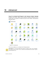
Figure 10-1: Advanced ..................................................................................................................... 10-1
1-10
Revision: 2012-02-29
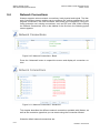
1
Related Documents
[1] Schmid Telecom, Watson SHDSL Router Manual
[2] Schmid Telecom, Watson Ethernet Manual
Revision: 2012-02-29
1-1
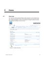
2
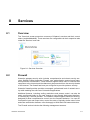
2.1
Overview
Introduction
Watson SHDSL router is an innovative Next-Generation DSL solution designed for
enabling high-speed Internet or point-to-point connectivity to business customers.
Watson SHDSL router uses Ethernet in the First Mile (EFM) technology, which is a
transparent extension of Ethernet-base LANs into wide area networks. No conversion of packet formats is required when transiting between LAN and WAN. This
transparency greatly simplifies network operations, reduces deployment costs, and
increase service levels. EFM includes maintenance function that make the operation of large wide-area Ethernets feasible.
Watson SHDSL router features either two or four SHDSL ports. Symmetrical data
rates up to 5.7 Mbit/s are available on each copper pair. Using EFM pair bonding,
data rates of 22.8 Mbit/s over 4 copper pairs can be achieved.
Watson SHDSL router integrates an eight port Ethernet switch, an SPI Firewall and
a VPN gateway, which protects networks by providing robust security features and
standard IPSec Virtual Private Network tunneling.
Watson SHDSL router features a user-friendly graphical Web-based management
interface. This highly intuitive GUI is easily mastered by the novice user, but is also
highly flexible and offers sophisticated users and system administrators full control
of the system.
This document describes the Watson SHDSL Router Web-based management
with SW version 4.11.2.
Revision: 2012-02-29
2-1
3
Getting Started
Connecting your computer or home network to the Watson SHDSL router is a simple procedure, varying slightly depending on your operating system.
The setup is designed to seamlessly integrate Watson with your computer or home
network. Moreover, zero-configuration is attained when taking advantage of Universal Plug-and-Play support in Windows XP.
The Windows default network settings dictate that in most cases the setup procedure described below will be unnecessary. For example, the default DHCP setting
in Windows XP is ‘client‘, requiring no further modification.
However, it is advised to follow the setup procedure described below to verify that
all communication parameters are valid and that the physical cable connections are
correct.
3.1
Introduction
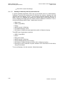
The basic setup procedure consists of the following stages:
1. LAN and DSL connections [3.2]
2. PC network configuration [3.3]
3. Waston SHDSL router configuration [3.4]
3.2
LAN and DSL Connections
Your computer can connect to the gateway using one of the Ethernet interfaces
that are available at the back of the Watson SHDSL router.
Consult Schmid Telecom, Watson SHDSL Router Manual [1] regarding the installation of your DSL connection.
3.3
PC Network Configuration
Each network interface on the PC should either be configured with a statically defined IP address and DNS address, or should be instructed to automatically obtain
an IP address using the Network DHCP server. Watson provides a DHCP server
on its LAN and it is recommended to configure your LAN to obtain its IP and DNS
server IPs automatically.
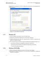
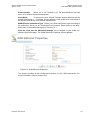
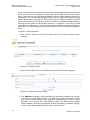
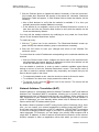
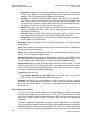
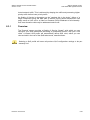
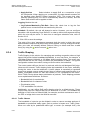
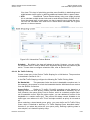
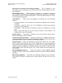
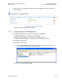
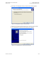
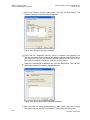
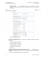
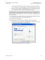
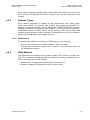
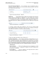
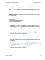
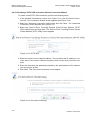
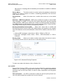
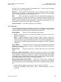
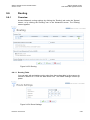
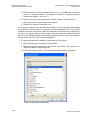
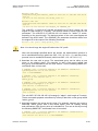
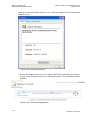
This configuration principle is identical but performed differently on each operating
system. Figure 3-1 displays the ‘TCP/IP Properties‘ dialog box as it appears in
Revision: 2012-02-29
3-1
Watson SHDSL Router
Web-based Management Manual
Watson-SHDSL-Router-GUI-Manual.doc
Version 2.3-03
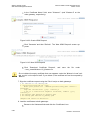
Windows XP. Following are TCP/IP configuration instructions for all supported operating systems.
Figure 3-1: IP and DNS Configuration
3.3.1
Windows XP
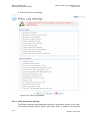
1. Access ‘Network Connections‘ from the Control Panel.
2. Right-click the Ethernet connection icon, and select ‘Properties‘.
3. Under the ‘General‘ tab, select the ‘Internet Protocol (TCP/IP)‘ component, and
press the ‘Properties‘ button.
4. The ‘Internet Protocol (TCP/IP)‘ properties window will be displayed (Figure 3-1).
Select the ‘Obtain an IP address automatically‘ radio button.
Select the ‘Obtain DNS server address automatically‘ radio button.
Click ‘OK‘ to save the settings.
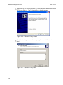
3.3.2
Windows 2000/98/Me
1. Access ‘Network and Dialing Connections‘ from the Control Panel.
2. Right-click the Ethernet connection‘s icon, and select ‘Properties‘ to display the
connection‘s properties.
3-2
Revision: 2012-02-29
Watson-SHDSL-Router-GUI-Manual.doc
Version 2.3-03
Watson SHDSL Router
Web-based Management Manual
3. Select the ‘Internet Protocol (TCP/IP)‘ component, and press the ‘Properties‘ button.
4. The ‘Internet Protocol (TCP/IP)‘ properties will be displayed.
Select the ‘Obtain an IP address automatically‘ radio button.
Select the ‘Obtain DNS server address automatically‘ radio button.
Click 'OK' to save the settings.
3.3.3
Linux
1. Login into the system as a super-user, by entering ‗su‘ at the prompt.
2. Type ‘ifconfig‘ to display the network devices and allocated IP‘s.
3. Type ‘pump -i <dev>‘, where <dev> is the network device name.
4. Type ‘ifconfig‘ again to view the new allocated IP address.
5. Make sure no firewall is active on device <dev>.
3.4
Watson Configuration
In order to configure your Watson SHDSL router you need to access Watson‘s
Web-based management.
To access the Web-based management:
1. Launch a Web-browser on a computer in the LAN.
2. Type the gateway‘s IP address. The default IP address is 192.168.1.1 .
3. Enter your username and password to log on to the WBM. The default user
name is ‘admin‘, and the default password is ‘admin‘.
Refer to Section 4 if you need more informations on how to use the web-based
management.
Revision: 2012-02-29
3-3
Watson SHDSL Router
Web-based Management Manual
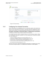
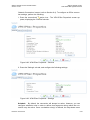
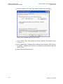
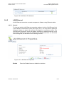
3.4.1
Watson-SHDSL-Router-GUI-Manual.doc
Version 2.3-03
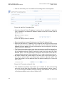
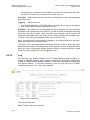
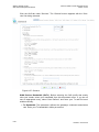
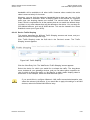
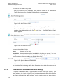
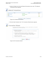
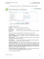
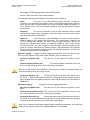
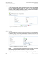
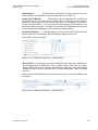
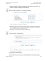
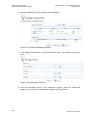
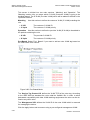
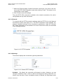
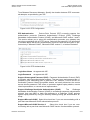
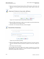
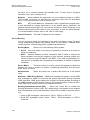
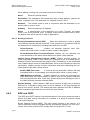
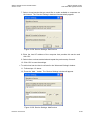
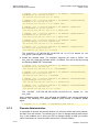
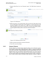
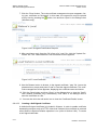
Configuring your DSL connection
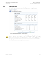
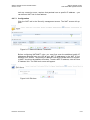
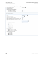
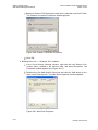
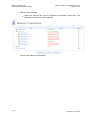
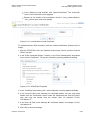
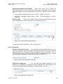
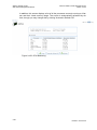
Select ‗Internet Connection‘ and then ‗Settings‘. The Internet Connection Settings
screen appears.
Figure 3-2: Internet Connection – DSL Settings
Refer to section 6.2 for a detailed description of the DSL Settings.
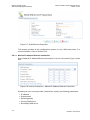
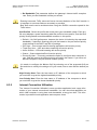
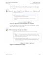
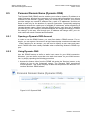
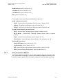
3.4.2
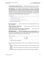
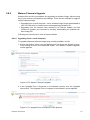
Configuring Your Internet Connection
When subscribing to a broadband service, you should be aware of the method by
which you are connected to the Internet. Technical information regarding the properties of your Internet connection should be provided by your Internet Service Provider (ISP). For example, your ISP should inform you whether you are connected to
the Internet using a static or dynamic IP address, or what protocols, such as PPTP
or PPPoE, you will be using to communicate over the Internet.
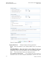
Refer to Section 5.3 if you want to use the wizard that automatically diagnoses your
network environment and configures Watson‘s internet connection.
3-4
Revision: 2012-02-29
Watson-SHDSL-Router-GUI-Manual.doc
Version 2.3-03
Watson SHDSL Router
Web-based Management Manual
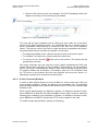
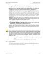
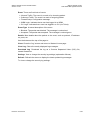
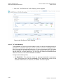
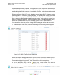
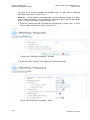
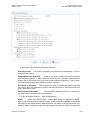
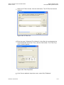
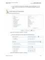
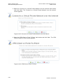
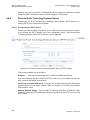
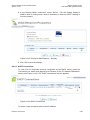
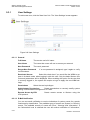
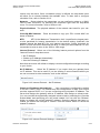
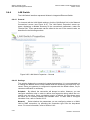
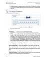
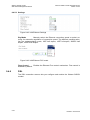
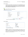
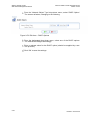
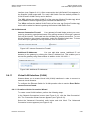
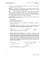
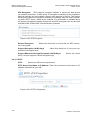
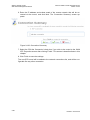
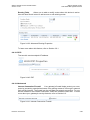
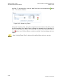
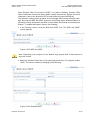
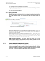
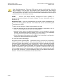
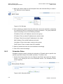
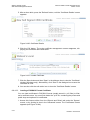
Refer to 5.4 to learn how to manualy configure your internet connection using the
quick setup.
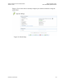
Figure 3-3: Quick Setup
Revision: 2012-02-29
3-5
4
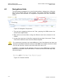
Using the Web-based Management
This chapter describes how to use Watson Web-based management, which allows
you to control all Watson‘s features and system parameters, using a user-friendly
graphical interface.
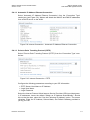
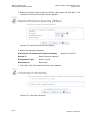
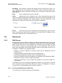
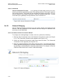
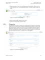
4.1
Accessing the Web-based Management
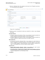
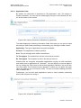
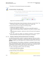
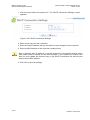
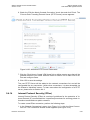
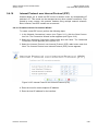
To access the Web-based management:
4. Launch a Web-browser on a computer in the LAN.
5. Type the gateway‘s IP address. The default IP address is 192.168.1.1 .
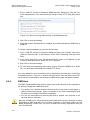
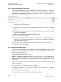
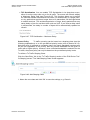
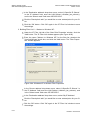
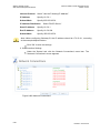
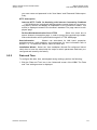
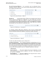
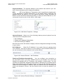
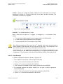
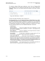
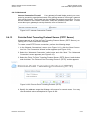
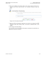
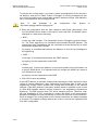
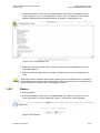
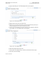
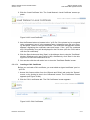
6. Enter your username and password to log on to the WBM. For security reasons,
you should change these settings after the initial login. The default user name is
’admin’, and the default password is ’admin’.
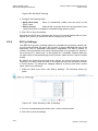
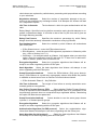
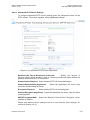
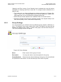
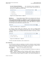
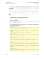
Figure 4-1: Web-based Management Login
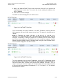
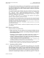
Your session will automatically time-out after a few minutes of inactivity. If you try to
operate the Web-based management after the session has expired the ‘Login
screen will appear and you will have to re-enter your user name and password before proceeding. This feature helps to prevent unauthorized users from accessing
the web-based management and changing the gateway‘s settings
Note: If your computer is running an operating system that supports UPnP, such Windows XP, you can easily add the computer to your home network and access the
Web-based management directly from within Windows.
Revision: 2012-02-29
4-1
Watson SHDSL Router
Web-based Management Manual
4.2
Watson-SHDSL-Router-GUI-Manual.doc
Version 2.3-03
Navigational Aids
The Web-based management is a user-friendly interface, designed as a Web site
that can be explored with any Web browser. This section illustrates the WBM's
page structure and describes its navigational components and their hierarchial
manner.
Figure 4-2: Navigation Components
1. The top level navigational aids are the Tabs, grouping the WBM screens into
several main subject areas.
2. Each tab has an Items Menu, listing the different menu items relevant for the
subject.
3. A menu item may have a Links Bar, located at the top-right of the screen. These
links further divide the menu item into different subjects.
For convenience purposes, the entire WBM part of this User Manual has been constructed in accordance with the structure of the WBM—the chapter structure is identical to the tab structure, sections are written after item menus, etc.
In addition, a constant link bar appears at the top of every WBM page, providing
shortcuts to information and control actions. These links include the site map, help,
reboot and logout.
Figure 4-3: Constant Link Bar
4-2
Revision: 2012-02-29
Watson-SHDSL-Router-GUI-Manual.doc
Version 2.3-03
4.3
Watson SHDSL Router
Web-based Management Manual
Managing Tables
Tables are structures used throughout the Web-based management. They handle
user-defined entries relating to elements such as network connections, restrictions
and configurable parameters. The principles outlined in this section apply to all tables in the WBM.
Figure 4-4: Typical Table Structure
Figure 4-4 illustrates a typical table. Each row defines an entry in the table. The following buttons, located in the 'Action' column, enable performing various actions on
the table entries.
Use the Add action icon to add a row to the table.
Use the Edit action icon to edit a row in the table.
Use the Remove action icon to remove a row from the table.
Use the Download action icon to download a file from the table.
Use the Copy action icon to copy an item to the clipboard.
Use the Move Up action icon to move a row one step up in the table.
Use the Move Down action icon to move a row one step down in
the table.
Revision: 2012-02-29
4-3
5
5.1
Home
Overview
The 'Overview' screen presents Watson's status summary in one convenient location. You can quickly and efficiently view important details of your connection status
and hardware peripherals, as well as the statuses of Watson's different services.
The following is the default 'Overview' screen.
Figure 5-1: Watson Overview
Revision: 2012-02-29
5-1
Watson SHDSL Router
Web-based Management Manual
5.2
Watson-SHDSL-Router-GUI-Manual.doc
Version 2.3-03
Map View
The network map depicts the various network elements, such as the Internet connection, firewall, gateway, internal network interface and local network computers
and peripherals.
Figure 5-2: The Network Map
The following table explains the meaning of different network map symbols:
Represents the Internet. Click this icon to configure the SHDSL
connction and the WAN interface (refer to Section 6.1).
Represents the gateway's Firewall. The height of the wall corresponds to the security level currently selected: Minimum, Typical or
Maximum. Click this icon to configure the Firewall (refer to Section
8.2).
Represents the Watson SHDSL router. Click this icon to go to the
System overview screen, showing the Software and Hardware version of Watson (refer to Section 9.1).
Represents a computer (host) connected in the home network. Each
computer recognized and granted a DHCP lease appears on the
network map. Click an icon to view network information for the corresponding computer.
5.3
Installation Wizard
Once your gateway is physically connected, Watson provides an Installation Wizard
that automatically diagnoses your network environment and configures its components. As explained in its first screen, the installation wizard is a step-by-step procedure that guides you through establishing an Internet connection. The wizard
5-2
Revision: 2012-02-29
Watson-SHDSL-Router-GUI-Manual.doc
Version 2.3-03
Watson SHDSL Router
Web-based Management Manual
progress box, located at the right hand side of the screen, provides a monitoring
tool for the wizard's steps during the installation progress.
Figure 5-3: Installation Wizard
To start the installation wizard, click 'Next'. The wizard procedure will start, performing the steps listed in the progress box consecutively, stopping only if a step fails or
if input is required. The following sections describe the wizard steps along with their
success/failure scenarios. If a step fails, use the 'Retry' or 'Skip' buttons to continue.
5.3.1
Step 1: Analyze Internet Connection Type
The first step is an analysis of your Internet connection.
Figure 5-4: Test Internet Connection
This step may fail if Watson cannot detect your Internet connection type or if your
DSL connection is not established.
In this case, the screen changes to the following.
Revision: 2012-02-29
5-3
Watson SHDSL Router
Web-based Management Manual
Watson-SHDSL-Router-GUI-Manual.doc
Version 2.3-03
Figure 5-5: Test Internet Connection – Failure
In this case, you can manually set the Internet connection type, by clicking the corresponding button.
To learn about manually configuring your Internet connection, refer to Section
5.4.1.
5.3.2
Step 2: Setup Internet Connection
If your Internet connection requires login details provided by your Internet Service
Provider (ISP) (e.g. when using PPPoE), enter your user name and password.
Failure to enter the correct details yields an error message. Click 'Back' and try
again.
5.3.3
Step 3: Test Service Provider Connection
This step tests the connectivity to your ISP.
5.3.4
Step 4: Test Internet Connection
This step tests the connectivity to the Internet.
5.3.5
Step 5: Installation Completed
This screen provides a summary of all the above Internet connection configuration
steps and their results. Click 'Finish' to complete the wizard procedure.
5.4
Quick Setup
'Quick Setup' enables speedy and accurate configuration of your Internet connection and other important parameters. The following sections describe these various
configuration parameters. Whether you configure these parameters or use the default ones, click 'OK' to enable your Internet connection.
5-4
Revision: 2012-02-29
Watson-SHDSL-Router-GUI-Manual.doc
Version 2.3-03
Watson SHDSL Router
Web-based Management Manual
Figure 5-6: Quick Setup
5.4.1
Configuring Your Internet Connection
When subscribing to a broadband service, you should be aware of the method by
which you are connected to the Internet. Technical information regarding the properties of your Internet connection should be provided by your Internet Service Provider (ISP). For example, your ISP should inform you whether you are connected to
the Internet using a static or dynamic IP address, or what protocols, such as PPTP
or PPPoE, you will be using to communicate over the Internet.
Your WAN connection can be configured using one of the following methods. Read
the configuration instructions relevant to you, by selecting your connection method
from the following list:
Manual IP Address Ethernet Connection [Section 5.4.1.1]
Automatic IP Address Ethernet Connection [Section 5.4.1.2]
Point-to-Point Tunneling Protocol (PPTP) [Section 5.4.1.3]
Point-to-point protocol over Ethernet (PPPoE) [Section 5.4.1.4]
No Internet connection [Section 5.4.1.5]
Click the 'Click here for Advanced Settings' link at anytime to navigate to your WAN
connection's properties page. The 'WAN Ethernet Properties' screen appears.
Revision: 2012-02-29
5-5
Watson SHDSL Router
Web-based Management Manual
Watson-SHDSL-Router-GUI-Manual.doc
Version 2.3-03
Figure 5-7: WAN Ethernet Properties
This screen provides all the configuration options for your WAN connection. For
more information, refer to Section 9.4.3.
5.4.1.1 Manual IP Address Ethernet Connection
Select 'Manual IP Address Ethernet Connection' from the 'Connection Type' combo
box:
Figure 5-8: Internet Connection - Manual IP Address Ethernet Connection
According to your service provider's instructions, specify the following parameters:
5-6
IP address
Subnet mask
Default gateway
Primary DNS server
Secondary DNS server
Revision: 2012-02-29
Watson-SHDSL-Router-GUI-Manual.doc
Version 2.3-03
Watson SHDSL Router
Web-based Management Manual
5.4.1.2 Automatic IP Address Ethernet Connection
Select 'Automatic IP Address Ethernet Connection' from the 'Connection Type'
combo-box (see Figure 5-9). Watson will obtain the WAN IP and DNS IP addresses
from a DHCP server on the WAN.
Figure 5-9: Internet Connection - Automatic IP Address Ethernet Connection
5.4.1.3 Point-to-Point Tunneling Protocol (PPTP)
Select 'Point-to-Point Tunneling Protocol (PPTP)' from the 'Connection Type' combo box:
Figure 5-10: Internet Connection - PPTP
Configure the following parameters according to your ISP information:
PPTP Server Host Name or IP Address
Login User Name
Login Password
Select the Internet Protocol: Most Internet Service Providers (ISPs) provide dynamic IP addresses, hence the default "Obtain an IP Address Automatically". Should
this not be the case, select the "Use the Following IP Address" option. The screen
refreshes. Enter the IP Address, Subnet Mask, and Default Gateway provided to
you by your ISP.
Revision: 2012-02-29
5-7
Watson SHDSL Router
Web-based Management Manual
Watson-SHDSL-Router-GUI-Manual.doc
Version 2.3-03
Figure 5-11: PPTP - Static IP Address
5.4.1.4 Point-to-point protocol over Ethernet (PPPoE)
Select 'Point-to-point protocol over Ethernet (PPPoE)' from the 'Connection Type'
combo box:
Figure 5-12: Internet Connection - PPPoE
Your Internet Service Provider (ISP) should provide you with the following information:
Login user name
Login password
5.4.1.5 No Internet Connection
Select 'No Internet Connection' from the 'Connection Type' combo-box (see Figure
5-13). Choose this connection type if you do not have an Internet connection, or if
you want to disable all existing connections.
Figure 5-13: Internet Connection - No Internet Connection
5.4.2
Quick Setup Completed
Watson does not require further configuration in order to start working. After the
setup described in this chapter, you can immediately start using your gateway to:
5-8
Revision: 2012-02-29
Watson-SHDSL-Router-GUI-Manual.doc
Version 2.3-03
Watson SHDSL Router
Web-based Management Manual
Share a broadband connection among multiple users (HTTP, FTP, Telnet,
NetMeeting) and between all of the computers connected to your home network.
Build a home network by connecting additional PCs and network devices to the
gateway.
Share resources (file servers, printers, etc.) between computers in the home
network using their names; auto-learning DNS enables Watson to automatically
detect the network identification names of the LAN PCs, enabling mutual communication using names, not IP addresses.
Control network parameters, including DHCP, DNS and WAN settings.
View network status, traffic statistics, system log and more.
Allow access from the Internet to services provided by computers in the home
network.
Prohibit computers in the home network from accessing selected services on
the Internet.
Block access to specific Internet Web sites from your home network.
To learn about how to configure your Firewall security parameters, refer to Section
8.2. If you wish to apply corporate-grade security to your network, refer to Section
8.2.11. If your gateway is equipped with multiple LAN ports, you can connect additional devices directly to the gateway. Otherwise, connect a hub or switch to the
LAN port, to which you can connect additional devices. In both cases, configure
newly connected devices to automatically obtain IP address as described above.
Revision: 2012-02-29
5-9
6
6.1
Internet Connection
Overview
The 'Overview' screen provides general information regarding your SHDSL Connection and your Internet conncetion such as DSL link status, connection speed, internet connection's status, connection duration, and Internet address. Refer to this
screen for a quick status reference.
Figure 6-1: Internet Connection – Overview
The following links are available:
Have Internet Connection problems? Click here This link routes you to the
'Diagnostics' screen under the 'Internet Connection' tab, where you can run
tests in order to diagnose and resolve Internet connectivity problems (for more
information, refer to Section 6.3).
Click Here For Internet Connection Utilization Click this link to analyze the
traffic usage of your WAN connection (for more information, refer to Section
8.3.2).
Revision: 2012-02-29
6-1
Watson SHDSL Router
Web-based Management Manual
6.2
Watson-SHDSL-Router-GUI-Manual.doc
Version 2.3-03
Settings
The 'Settings' screen provides basic configuration options for the SHDSL modem
and for the different types of Internet connections supported by Watson.
Figure 6-2: Internet Connection – Settings
Ethernet Encapsulation (TC Flow)
Select either ‘EFM‘ or ‘HDLC‘ encapsulation. ‗HDLC‘ encapsulation should be selected when the Watson SHDSL router is
connected to a another Watson modem supporting ‗HDLC‘ encapsulation. ‗EFM‘
should be selected when two Watson SHDSL routers are connected point-to-point
together or when the Watson SHDSL router is connected to another SHDSL EFM
compatible device.
DSL Master (Sub Type)
Select ‗off (STU-R)‘ or ‗on (STU-C)‘. If two Watson
SHDSL router are connected point-to-point, one device has to be set to ‗off‘ and the
other device has to be set to ‗on‘. Use ‗off (STU-R)‘ when the Watson SHDSL router is connected to a Watson Ethernet plug-in (SZ.866.V654) [2]. Some DSL port
settings are only visible when DSL Master is ‗on (STU-C)‘.
6-2
Admin State
Select ‗up‘ or ‗down‘. Allows to block certain ports and alarms.
Line Rate [kb/s]
Enter the line rate of the ports.
Constellation
Select ‗pam16‘ or ‗pam32‘ or ‗pam64‘ or ‗pam128‘ .
Revision: 2012-02-29
Watson-SHDSL-Router-GUI-Manual.doc
Version 2.3-03
Watson SHDSL Router
Web-based Management Manual
Power Backoff
Select ‗on‘ or ‗off‘. Default is ‗off‘. For short distances you can
turn it on to reduce the transmitted power.
Clock Mode
To connect to other Schmid Telecom Watson devices use the
default clock mode ‗1‘. If needed, choose another clock mode when connected to
an SHDSL EFM device from another manufacturer.
WAN Ethernet Connection Type Select your WAN connection type according to
the method by which you are connected to the Internet. Each option in this dropdown menu is described thoroughly in Section 5.4.1.
Click the 'Click here for Advanced Settings' link to navigate to your WAN connection's properties page. The 'WAN Ethernet Properties' screen appears.
Figure 6-3: WAN Ethernet Properties
This screen provides all the configuration options for your WAN connection. For
more information, refer to Section 9.4.3.
Revision: 2012-02-29
6-3
Watson SHDSL Router
Web-based Management Manual
6.3
Watson-SHDSL-Router-GUI-Manual.doc
Version 2.3-03
Diagnostics
The 'Diagnostics' screen provides a series of tests aimed at validating your gateway's Internet connection.
Figure 6-4: Internet Connection – Diagnostics
Click 'Run' to begin the test routine. While testing is in progress, you may abort the
diagnostics process by using the 'Abort' button. Should a failure message appear,
click 'Repair' to initiate the Installation Wizard procedure (refer to Section 5.3).
Figure 6-5: Diagnostics Process
6-4
Revision: 2012-02-29
Watson-SHDSL-Router-GUI-Manual.doc
Version 2.3-03
6.4
Watson SHDSL Router
Web-based Management Manual
SHDSL Status
The 'SHDSL Status' screen provides the SHDSL port status and performance.
Figure 6-6: Internet Connection – SHDSL Status
Note: an important value to monitor is the ‘RX SNR Margin’. The RX SNR Margin
should no be smaller than 4 dB to garanty good and reliable SHDSL performance. If
the value is too small the linerate should be reduced to increase the RX SNR Margin.
Click 'Clear Counters' to reset the performance counters.
Revision: 2012-02-29
6-5
7
7.1
Local Network
Overview
The 'Overview' screen presents your local network summary. This includes all connected devices. When this screen is loaded, Watson begins the process of automatically detecting the network services available on connected computers (hosts).
Figure 7-1: Local Network Overview
Revision: 2012-02-29
7-1
Watson SHDSL Router
Web-based Management Manual
Watson-SHDSL-Router-GUI-Manual.doc
Version 2.3-03
To view more information on a specific computer, click its respective link. The 'Host
Information' screen appears.
Figure 7-2: Host Information
This screen presents all of the information relevant to the connected computer,
such as connection information, available services, traffic statistics, and connection
list. It also enables you to perform connectivity tests with the computer.
Services This section lists the services on the computer that are available to other
computers from the LAN. Services are accessible only when enabled on the computer. When a service is accessible from the LAN, you can activate it by either
clicking its name or the URL that appears. Available services are:
Shared Files Access the computer's shared files directory.
HTTP
Access the computer's HTTP server (if available).
FTP
Open an FTP session with the computer.
Telnet Open a Telnet session with the computer.
Remote Desktop
Remotely control a Windows computer with the Remote Desktop utility.
VNC
Remotely control the computer with the Virtual Network Computing
desktop protocol.
Add Access Control Rule
Block access to Internet services from the computer, or allow access if the firewall is set to a "High" security level (for more information, refer to Section 8.2.2).
Add Port Forwarding Rule
Expose services on the computer to external Internet users (for more information, refer to Section 8.2.3).
Connection Information This section displays various details regarding the
computer's connection settings. To view the connection's properties, click the network connection type ('Bridge' in the above example). The relevant properties
7-2
Revision: 2012-02-29
Watson-SHDSL-Router-GUI-Manual.doc
Version 2.3-03
Watson SHDSL Router
Web-based Management Manual
screen appears (for more information, refer to Section 9.4). In addition, you can run
a Ping or ARP test by clicking the respective 'Test Connectivity' button. The tests
are performed in the 'Diagnostics' screen (refer to Section 9.8.8).
Statistics This section displays the computer's traffic statistics, such as the
number and size of transmitted and received packets.
Connection List
This section displays the list of connections opened by the
computer on Watson's firewall. The table displays the computer's source LAN IP
address and port, the gateway's IP address and port to which it is translated, and
the destination WAN IP address and port.
7.2
Device View
The 'Device View' screen presents a summary of Watson's LAN devices and the
status of each one (connected/disconnected).
Figure 7-3: Local Network Device View
Revision: 2012-02-29
7-3
8
8.1
Services
Overview
The 'Overview' screen presents a summary of Watson's services and their current
status (enabled/disabled). These services are configurable via their respective tabs
under the 'Services' main tab.
Figure 8-1: Services Overview
8.2
Firewall
Watson's gateway security suite includes comprehensive and robust security services: Stateful Packet Inspection Firewall, user authentication protocols and password protection mechanisms. These features together allow users to connect their
computers to the Internet and simultaneously be protected from the security threats
of the Internet. The firewall has been pre-configured to provide optimum security.
Watson's firewall provides provides a managed, professional level of network security while enabling the safe use of interactive applications.
Additional features, including surfing restrictions and access control, can also be
easily configured locally by the user through a user-friendly Web-based interface,
or remotely by a service provider. The Watson firewall supports advanced filtering,
designed to allow comprehensive control over the firewall's behavior. You can define specific input and output rules, control the order of logically similar sets of rules
and make a distinction between rules that apply to WAN and LAN network devices.
The Firewall service includes the following management screens:
Revision: 2012-02-29
8-1
Watson SHDSL Router
Web-based Management Manual
Watson-SHDSL-Router-GUI-Manual.doc
Version 2.3-03
The 'Overview' screen allows you to choose the security level for the firewall
(refer to Section 8.2.1)
The 'Access Control' screen can be used to restrict access from the home
network to the Internet (refer to Section 8.2.2).
The 'Port Forwarding' screen can be used to enable access from the Internet
to specified services provided by computers in the home network and special
Internet applications (refer to Section 8.2.3).
The 'DMZ Host' screen allows you to configure a LAN host to receive all traffic
arriving at your gateway, which does not belong to a known session (refer to
Section 8.2.4
The 'Port Triggering' screen allows you to define port triggering entries, to dynamically open the firewall for some protocols or ports (refer to Section 8.2.5).
The 'Website Restrictions' screen allows you to block LAN access to a certain
host or Web site on the Internet (refer to Section 8.2.6).
The 'NAT' screen allows you to manually control the translation of network addresses and ports (refer to Section 8.2.7).
The 'Connections' screen allows you to view all the connections that are currently open (refer to Section 8.2.8).
The 'Advanced Filtering' screen allows you to implicitly control the firewall setting and rules (refer to Section 8.2.9).
The 'Log' screen allows you to view and configure the firewall Log (refer to
Section 8.2.9.2).
8.2.1
Overview
Use the 'General' screen to configure the gateway's basic security settings.
Figure 8-2: General
The firewall regulates the flow of data between the home network and the Internet.
Both incoming and outgoing data are inspected and then either accepted (allowed
to pass through Watson) or rejected (barred from passing through Watson) accord8-2
Revision: 2012-02-29
Watson-SHDSL-Router-GUI-Manual.doc
Version 2.3-03
Watson SHDSL Router
Web-based Management Manual
ing to a flexible and configurable set of rules. These rules are designed to prevent
unwanted intrusions from the outside, while allowing home users access to the Internet services that they require.
The firewall rules specify what types of services available on the Internet may be
accessed from the home network and what types of services available in the home
network may be accessed from the Internet. Each request for a service that the
firewall receives, whether originating in the Internet or from a computer in the home
network, is checked against the set of firewall rules to determine whether the request should be allowed to pass through the firewall. If the request is permitted to
pass, then all subsequent data associated with this request (a "session") will also
be allowed to pass, regardless of its direction.
For example, when you point your Web browser to a Web page on the Internet, a
request is sent out to the Internet for this page. When the request reaches Watson
the firewall will identify the request type and origin–-HTTP and a specific PC in your
home network, in this case. Unless you have configured access control to block requests of this type from this computer, the firewall will allow this request to pass out
onto the Internet (refer to Section 8.2.2 for more on setting access controls). When
the Web page is returned from the Web server the firewall will associate it with this
session and allow it to pass, regardless of whether HTTP access from the Internet
to the home network is blocked or permitted. The important thing to note here is
that it is the origin of the request, not subsequent responses to this request, that
determines whether a session can be established or not. These services include
Telnet, FTP, HTTP, HTTPS, DNS, IMAP, POP3 and SMTP. The list of allowed services at 'Maximum Security' mode can be edited in the Access Control page. Attention: Some applications (such as some Internet messengers and Peer-To-Peer client applications) tend to use these ports, if they cannot connect with their own default ports. When applying this behavior, these applications will not be blocked outbound, even at Maximum Security Level.
To configure Watson's security settings, perform the following:
1. Choose between the three predefined security levels described in the table
above.
Note: Using the Minimum Security setting may expose the home network to significant
security risks, and thus should only be used, when necessary, for short periods of
time.
2. Check the 'Block IP Fragments' box in order to protect your home network from a
common type of hacker attack that could make use of fragmented data packets
to sabotage your home network. Note that VPN over IPSec and some UDPbased services make legitimate use of IP fragments. You will need to allow IP
fragments to pass into the home network in order to make use of these select
services.
3. Click 'OK' to save the settings.
8.2.2
Access Control
You may want to block specific computers within the home network (or even the
whole network) from accessing certain services on the Internet. For example, you
may want to prohibit one computer from surfing the Web, another computer from
transferring files using FTP, and the whole network from receiving incoming e-mail.
Revision: 2012-02-29
8-3
Watson SHDSL Router
Web-based Management Manual
Watson-SHDSL-Router-GUI-Manual.doc
Version 2.3-03
Access Control defines restrictions on the types of requests that may pass from the
home network out to the Internet, and thus may block traffic flowing in both directions. It can also be used for allowing specific services when maximum security is
configured. In the e-mail example given above, you may prevent computers in the
home network from receiving e-mail by blocking their outgoing requests to POP3
servers on the Internet. There are numerous services you should consider blocking,
such as popular game and file sharing servers. For example, if you want to make
sure that your employees do not put your business at risk from illegally traded copyright files, you may want to block several popular P2P and file sharing applications.
To allow or restrict services:
Click 'Access Control' under the Firewall menu. The 'Access Control' screen
appears.
Figure 8-3: Access Control
Click the 'New Entry' link. The 'Add Access Control Rule' screen appears.
Figure 8-4: Add Access Control Rule
The ‗Address’ drop-down menu provides you the ability to specify the computer or group of computers for which you would like to apply the access control
rule. You can select between any, a specific computer in your LAN, or 'User
Defined'. If you choose the 'User Defined' option, the 'Edit Network Object'
screen appears. Specifying an address is done by creating a 'Network Object';
to learn more about network objects, refer to Section 9.9.2.
8-4
Revision: 2012-02-29
Watson-SHDSL-Router-GUI-Manual.doc
Version 2.3-03
Watson SHDSL Router
Web-based Management Manual
The ‗Protocol’ drop-down menu menu lets you select or specify the type of
protocol that will be used. Selecting the 'Show All Services' option will expand
the list of available protocols. Select a protocol or add a new one using the
'User Defined' option. This will commence a sequence that will add a new service, representing the protocol. Refer to Section 9.9.1 in order to learn how to
do so.
Select the 'Reply an HTML page to the blocked client' check-box to display the
following message to the client: "Access Denied - this computer is not allowed
to surf the WAN. Please contact your admin.". When this check box is unselected, the client's packets are simply ignored and no notification is issued.
The 'Schedule' drop-down menu allows you to define the time period during
which this rule will take effect. By default, the rule will always be active. However, you can configure scheduler rules by selecting 'User Defined'. To learn how
to configure scheduler rules, refer to Section 9.9.3.
Click the 'OK' button to save your changes. The 'Access Control' screen displays a summary of the rule that you just added.
Figure 8-5: Access Control Rule
You may edit the access control rule by modifying its entry under the 'Local Host'
column in the 'Access Control' screen.
To modify an entry:
Click the
action icon for the rule. The 'Edit Access Control Rule' screen appears. This screen allows you to edit all the parameters that you configured
when creating the access control rule.
Figure 8-6: Edit Access Control Rule
Revision: 2012-02-29
8-5
Watson SHDSL Router
Web-based Management Manual
Watson-SHDSL-Router-GUI-Manual.doc
Version 2.3-03
Click the 'OK' button to save your changes and return to the 'Access Control'
screen.
You can disable an access control rule in order to make a service available without
having to remove the rule from the 'Access Control' screen. This may be useful if
you wish to make the service available only temporarily and expect that you will
want to reinstate the restriction in the future.
To temporarily disable a rule, clear the check box next to the service name.
To reinstate it at a later time, simply reselect the check box.
To remove a rule, click the
permanently removed.
action icon for the service. The service will be
Please note that when Web Filtering is enabled, HTTP services cannot be blocked by
Access Control.
8.2.3
Port Forwarding
In its default state, Watson blocks all external users from connecting to or communicating with your network. Therefore the system is safe from hackers who may
try to intrude on the network and damage it. However, you may want to expose
your network to the Internet in certain limited and controlled ways in order to enable
some applications to work from the LAN (game, voice and chat applications, for example) and to enable Internet-access to servers in the home network. The Port
Forwarding feature supports both of these functionalities. If you are familiar with
networking terminology and concepts, you may have encountered this topic referred to as "Local Servers".
The 'Port Forwarding' screen enables you to define the applications that require
special handling by Watson. All you have to do is select the application's protocol
and the local IP address of the computer that will be using or providing the service.
If required, you may add new protocols in addition to the most common ones provided by Watson. For example, if you wanted to use a File Transfer Protocol (FTP)
application on one of your PCs, you would simply select 'FTP' from the list and enter the local IP address or host name of the designated computer. All FTP-related
data arriving at Watson from the Internet will henceforth be forwarded to the specified computer.
Similarly, you can grant Internet users access to servers inside your home network,
by identifying each service and the PC that will provide it. This is useful, for example, if you want to host a Web server inside your home network. When an Internet
user points his/her browser to Watson's external IP address, the gateway will forward the incoming HTTP request to your Web server.
However, there is a limitation that must be considered. With one external IP address (Watson's main IP address), different applications can be assigned to your
LAN computers, however each type of application is limited to use one computer.
For example, you can define that FTP will use address X to reach computer A and
Telnet will also use address X to reach computer A, but attempting to define FTP to
use address X to reach both computer A and B will fail. Watson therefore provides
the ability to add additional public IP addresses to port forwarding rules, which you
must first obtain from your ISP, and enter into the 'NAT IP Addresses Pool' (refer to
Section 8.2.7). You will then be able to define FTP to use address X to reach computer A and address Y to reach computer B.
8-6
Revision: 2012-02-29
Watson-SHDSL-Router-GUI-Manual.doc
Version 2.3-03
Watson SHDSL Router
Web-based Management Manual
Additionally, port forwarding enables you to redirect traffic to a different port instead
of the one to which it was designated. For example, you have a Web server running
on your PC on port 8080 and you want to grant access to this server to anyone who
accesses Watson via HTTP. To accomplish this, you will have to define a port forwarding rule for the HTTP service, with the PC's IP or host name, as well as specify
8080 in the 'Forward to Port' field. All incoming HTTP traffic will now be forwarded
to the PC running the Web server on port 8080.
When setting a port forwarding service, you must ensure that the port is not already
in use by another application, which may stop functioning.
Note: Some applications, such as FTP, TFTP, PPTP and H323, require the support of
special specific Application Level Gateway (ALG) modules in order to work inside the
home network. Data packets associated with these applications contain information
that allows them to be routed correctly. An ALG is needed to handle these packets
and ensure that they reach their intended destinations. Watson is equipped with a robust list of ALG modules in order to enable maximum functionality in the home network. The ALG is automatically assigned based on the destination port.
To add a new port forwarding service, perform the following:
Click 'Port Forwarding' under the Firewall menu. The 'Port Forwarding' screen
appears.
Figure 8-7: Port Forwarding
Revision: 2012-02-29
8-7
Watson SHDSL Router
Web-based Management Manual
Watson-SHDSL-Router-GUI-Manual.doc
Version 2.3-03
Click the 'New Entry' link. The 'Add Port Forwarding Rule' screen appears.
Figure 8-8: Add Port Forwarding Rule
Select the 'Specify Public IP Address' check box if you would like to apply this
rule on Watson's non-default IP address, defined in the 'NAT' screen (refer to
Section 8.2.7).
Figure 8-9: Specify Public IP Address
Enter the additional external IP address in the 'Public IP Address' field.
Enter the host name or IP address of the computer that will provide the service
(the "server") in the 'Local Host' field. Note that unless an additional external IP
address has been added, only one LAN computer can be assigned to provide a
specific service or application.
The Protocol drop-down menu menu lets you select or specify the type of protocol that will be used. Selecting the 'Show All Services' option will expand the
list of available protocols. Select a protocol or add a new one using the 'User
Defined' option. This will commence a sequence that will add a new service,
representing the protocol. Refer to Section 8.9.1 in order to learn how to do so.
By default, Watson will forward traffic to the same port as the incoming port. If
you wish to redirect traffic to a different port, select the 'Specify' option. The
screen will refresh, and an additional field will appear enabling you to enter the
port number:
Figure 8-10: Forward to a Specific Port
The 'Schedule' drop-down menu allows you to define the time period during
which this rule will take effect. By default, the rule will always be active. However, you can configure scheduler rules by selecting 'User Defined'. To learn how
to configure scheduler rules, refer to Section 9.9.3.
8-8
Revision: 2012-02-29
Watson-SHDSL-Router-GUI-Manual.doc
Version 2.3-03
Watson SHDSL Router
Web-based Management Manual
1. Click the 'OK' button to save your changes. The 'Port Forwarding' screen will
display a summary of the rule that you just added.
Figure 8-11: Port Forwarding Rule
You may edit the port forwarding rule by clicking its entry under the 'Local Host'
column in the 'Port Forwarding' screen. You can disable the rule in order to make a
service unavailable without having to remove the rule from the 'Port Forwarding'
screen. This may be useful if you wish to make the service unavailable only temporarily and expect that you will want to reinstate it in the future.
To temporarily disable a rule, clear the check box next to the service name.
To reinstate it at a later time, simply reselect the check box.
To remove a rule, click the
permanently removed.
action icon for the service. The service will be
How many computers can use a service or play a game simultaneously? Well, the
answer may be a bit confusing. All the computers on the network can use a specific
service, as clients, simultaneously. Being a client means that the computer within
the network initiates the connection—for example, opens an FTP connection with
an FTP server on the Internet. But only one computer can serve as a server, responding to requests from computers on the Internet.
8.2.3.1 A Port Forwarding Example
In order to allow outside access (from the WAN) to a server inside your LAN, you
must configure Watson's firewall, by adding a port forwarding rule. The following
exercise demonstrates how to allow such access to an HTTP server located inside
Watson's LAN.
When remote administration is enabled on Watson, an attempt to browse to Watson's WBM from a WAN PC will yield the WBM's 'Home' page. However, when the
following port forwarding rule is defined on Watson, an attempt to browse to Watson's WBM from a WAN PC will yield the HTTP server located on the LAN.
To enable remote administration, perform the following:
Revision: 2012-02-29
8-9
Watson SHDSL Router
Web-based Management Manual
Watson-SHDSL-Router-GUI-Manual.doc
Version 2.3-03
1. From a LAN PC, browse to Watson's WBM and click 'Advanced'. Click the 'Remote Administration' icon, and check the 'Using Primary HTTP Port (80)' check
box.
Figure 8-12: Allow Incoming WAN Access to Web-Management
2. Click 'OK' to save the settings.
3. Verify that remote administration is enabled, by accessing Watson's WBM from a
WAN PC.
To define a port forwarding rule, perform the following:
1. From a LAN PC, browse to Watson's WBM and select the 'Firewall' menu item
under the 'Services' tab. In the links bar, select 'Port Forwarding', and click 'New
Entry'.
2. In the 'Local Host' field, enter the server's LAN PC name or IP address. In the
'Protocol' drop-down menu, select the 'HTTP' protocol.
3. Click 'OK' to save the settings.
4. To verify that port forwarding takes place, access Watson's WBM from a WAN
PC. You should be redirected to the LAN HTTP server.
You may disable the port forwarding rule by deselecting its check box in the 'Port
Forwarding' screen. If you try to access the local server from the WAN, the HTTP
server will not be accessible, and Watson's WBM 'Home' page will appear instead.
8.2.4
DMZ Host
The DMZ (Demilitarized) Host feature allows one local computer to be exposed to
the Internet. Designate a DMZ host when:
You wish to use a special-purpose Internet service, such as an on-line game or
video-conferencing program, that is not present in the Port Forwarding list and
for which no port range information is available.
You are not concerned with security and wish to expose one computer to all
services without restriction.
Warning: A DMZ host is not protected by the firewall and may be vulnerable to attack.
Designating a DMZ host may also put other computers in the home network at risk.
When designating a DMZ host, you must consider the security implications and protect it if necessary.
8-10
Revision: 2012-02-29
Watson-SHDSL-Router-GUI-Manual.doc
Version 2.3-03
Watson SHDSL Router
Web-based Management Manual
An incoming request for access to a service in the home network, such as a Webserver, is fielded by Watson. Watson will forward this request to the DMZ host (if
one is designated) unless the service is being provided by another PC in the home
network (assigned in Port Forwarding), in which case that PC will receive the request instead.
To designate a local computer as a DMZ Host:
Click 'DMZ Host' under the Firewall menu. The 'DMZ Host' screen appears.
Figure 8-13: DMZ Host
Enter the local IP address of the computer that you would like to designate as a
DMZ host, and select the check-box. Note that only one LAN computer may be
a DMZ host at any time.
Click 'OK' to save the settings.
You can disable the DMZ host so that it will not be fully exposed to the Internet, but
keep its IP address recorded on the 'DMZ Host' screen. This may be useful if you
wish to disable the DMZ host but expect that you will want to enable it again in the
future.
To disable the DMZ host so that it will not be fully exposed to the Internet, clear
the check-box next to the DMZ IP designation, and click 'OK'.
To reinstate it at a later time, simply reselect the check box.
8.2.5
Port Triggering
Port triggering can be used for dynamic port forwarding configuration. By setting
port triggering rules, you can allow inbound traffic to arrive at a specific LAN host,
using ports different than those used for the outbound traffic. This is called port
triggering since the outbound traffic triggers to which ports inbound traffic is directed.
For example, consider an application server that is accessed using UDP protocol
on port 2222. The application server responds by connecting the user using UDP
on port 3333 when starting the application sessions. In such a case you must use
port triggering, since this scenario conflicts with the following default firewall settings:
The firewall blocks inbound traffic by default.
The server replies to Watson's IP, and the connection is not sent back to your
host, since it is not part of a session.
In order to solve this you need to define a Port Triggering entry, which allows inbound traffic on UDP port 3333, only after a LAN host generated traffic to UDP port
2222. This will result in accepting the inbound traffic from the application server,
Revision: 2012-02-29
8-11
Watson SHDSL Router
Web-based Management Manual
Watson-SHDSL-Router-GUI-Manual.doc
Version 2.3-03
and sending it back to the LAN Host which originated the outgoing traffic to UDP
port 2222. Select the 'Port Triggering' tab in the 'Security' management screen. The
'Port Triggering' screen will appear. This screen will list all of the port triggering entries.
Figure 8-14: Port Triggering
Let's add an entry for the application server example above:
Figure 8-15: New Port Triggering Rule
1. Select the 'User Defined' option to add an entry. The 'Edit Port Triggering Rule'
screen will appear.
Enter a name for the service (e.g. "application_server"), and click the 'New Trigger
Ports' link. The 'Edit Service Server Ports' screen will appear.
In the Protocol combo-box, select UDP. The screen will refresh, providing source
and destination port options.
2. Leave the Source Ports combo-box at its default "Any". In the Destination Ports
combo-box, select "Single". The screen will refresh again, providing an additional field in which you should enter "2222" as the destination port.
3. Click 'OK' to save the settings.
Back in the 'Edit Port Triggering Rule' screen, click the 'New Opened Ports' link.
The 'Edit Service Opened Ports' screen will appear.
Similar to the trigger ports screen, select UDP as the protocol, leave the source
port at "Any", and enter a 3333 as the single destination port.
4. Click 'OK' to save the settings.
8-12
Revision: 2012-02-29
Watson-SHDSL-Router-GUI-Manual.doc
Version 2.3-03
Watson SHDSL Router
Web-based Management Manual
You can disable a port triggering rule without having to remove it from the 'Port
Triggering' screen.
To temporarily disable a rule, clear the check box next to the service name.
To reinstate it at a later time, simply reselect the check box.
To remove a rule, click the
permanently removed.
action icon for the service. The service will be
There may be a few default port triggering rules listed when you first access the
port triggering screen. Please note that disabling these rules may result in impaired
gateway functionality.
8.2.6
Website Restrictions
You may configure Watson to block specific Internet websites so that they cannot
be accessed from computers in the home network. Moreover, restrictions can be
applied to a comprehensive and automatically-updated table of sites to which access is not recommended.
To block access to a website:
1. Click the 'Website Restrictions' tab in the 'Security' management screen.
Figure 8-16: Website Restrictions
2. Click the 'New Entry' link. The 'Restricted Website' screen appears.
3. Enter the URL (or part of the URL) that you would like to make inaccessible from
your home network (all Web pages within this URL will also be blocked). If the
URL has multiple IP addresses, Watson will resolve all additional addresses and
automatically add them to the restrictions table.
4. The Local Host drop-down menu provides you the ability to specify the computer
or group of computers for which you would like to apply the website restriction.
You can select between any, a specific computer in your LAN, or 'User Defined'.
If you choose the 'User Defined' option, the 'Edit Network Object' screen appears. Specifying an address is done by creating a 'Network Object'; to learn
more about network objects, refer to Section 9.9.2.
5. The 'Schedule' drop-down menu allows you to define the time period during
which this rule will take effect. By default, the rule will always be active. However, you can configure scheduler rules by selecting 'User Defined'. To learn how
to configure scheduler rules, refer to Section 9.9.3.
6. Click 'OK' to save the settings.
Revision: 2012-02-29
8-13
Watson SHDSL Router
Web-based Management Manual
Watson-SHDSL-Router-GUI-Manual.doc
Version 2.3-03
7. Click the 'Refresh' button to update the status if necessary. If the site is successfully located then 'Resolved' will appear in the status bar, otherwise 'Hostname
Resolution Failed' will appear. In case Watson fails to locate the website, do the
following:
Use a Web browser to verify that the website is available. If it is, then you
probably entered the website address incorrectly.
If the website is not available, return to the 'Website Restrictions' screen at a
later time and click the 'Resolve Now' button to verify that the website can be
found and blocked by Watson.
You may edit the website restriction by modifying its entry under the 'Local Host'
column in the 'Website Restrictions' screen.
To modify an entry:
1. Click the
action icon for the restriction. The 'Restricted Website' screen appears. Modify the website address, group or schedule as necessary.
2. Click the 'OK' button to save your changes and return to the 'Website Restrictions' screen.
To ensure that all current IP addresses corresponding to the restricted websites are
blocked:
Click the 'Resolve Now' button. Watson will check each of the restricted website addresses and ensure that all IP addresses at which this website can be
found are included in the IP addresses column.
You can disable a restriction in order to make a website available again without
having to remove it from the 'Website Restrictions' screen. This may be useful if
you wish to make the website available only temporarily and expect that you will
want to block it again in the future.
To temporarily disable a rule, clear the check box next to the service name.
To reinstate it at a later time, simply reselect the check box.
To remove a rule, click the
permanently removed.
8.2.7
action icon for the service. The service will be
Network Address Translation (NAT)
Watson features a configurable Network Address Translation (NAT) and Network
Address Port Translation (NAPT) mechanism, allowing you to control the network
addresses and ports of packets routed through your gateway. When enabling multiple computers on your network to access the Internet using a fixed number of
public IP addresses, you can statically define which LAN IP address will be translated to which NAT IP address and/or ports.
By default, Watson operates in NAPT routing mode (refer to Section 8.4.8.3). However, you can control your network translation by defining static NAT/NAPT rules.
Such rules map LAN computers to NAT IP addresses. The NAT/NAPT mechanism
is useful for managing Internet usage in your LAN, or complying with various application demands. For example, you can assign your primary LAN computer with a
single NAT IP address, in order to assure its permanent connection to the Internet.
Another example is when an application server with which you wish to connect,
8-14
Revision: 2012-02-29
Watson-SHDSL-Router-GUI-Manual.doc
Version 2.3-03
Watson SHDSL Router
Web-based Management Manual
such as a security server, requires that packets have a specific IP address – you
can define a NAT rule for that address.
8.2.7.1 Configuration
Click the 'NAT' tab in the 'Security' management screen. The 'NAT' screen will appear .
Figure 8-17: Network Address Translation
Before configuring NAT/NAPT rules, you must first enter the additional public IP
addresses obtained from your ISP as your NAT IP addresses, in the 'NAT IP Addresses Pool' section. The primary IP address used by the WAN device for dynamic NAPT should not be added to this table. To add a NAT IP address, click the 'New
IP Address' link. The 'Edit Item' screen will appear.
Figure 8-18: Edit Item
Revision: 2012-02-29
8-15
Watson SHDSL Router
Web-based Management Manual
Watson-SHDSL-Router-GUI-Manual.doc
Version 2.3-03
Select between IP address, subnet or range in the 'Network Object Type' combo
box, and enter the information respectively. To add a new NAT/NAPT rule, click the
'New Entry' link in the 'NAT/NAPT Rule Sets' section. The 'Add NAT/NAPT Rule'
screen will appear.
Figure 8-19: Add NAT/NAPT Rule
This screen is divided into two main sections, 'Matching' and 'Operation'. The
'Matching' section defines the LAN addresses to be translated to the external addresses, which are defined in the 'Operation' section.
Matching Use this section to define characteristics of the packets matching the
rule.
Source Address The source address of packets sent or received by Watson.
The drop-down menu displays the names or IP addresses of the hosts currently
connected to Watson's LAN, as well as the options 'Any' and 'User Defined'.
Select an address or name from the list to apply the rule on the corresponding
host, or 'Any' to apply the rule on all Watson's LAN hosts. If you would like to
add a new address, select the 'User Defined' option in the drop-down menu.
This will commence a sequence that will add a new network object, representing the new host. Refer to Section 9.9.2 in order to learn how to do so.
Destination Address The destination address of packets sent or received by
Watson. This address can be configured in the same manner as the source
address. This entry enables further filtration of the packets.
Protocol You may also specify a traffic protocol. Selecting the 'Show All Services' option from the drop-down menu will expand the list of available protocols. Select a protocol or add a new one using the 'User Defined' option. This
will commence a sequence that will add a new service, representing the protocol. Refer to Section 8.9.1 in order to learn how to do so.
Operation Use this section to define the operation that will be applied on the IP
addresses matching the criteria defined above. The operations available are NAT
or NAPT. Selecting each from the combo box will refresh the screen accordingly.
8-16
Revision: 2012-02-29
Watson-SHDSL-Router-GUI-Manual.doc
Version 2.3-03
Watson SHDSL Router
Web-based Management Manual
NAT Addresses The NAT address into which the original IP address will be translated. The combo box displays all of your available NAT addresses/ranges, from
which you can select an entry. If you would like to add a single address or a subrange from the given pool/range, select the 'User Defined' option in the combo box.
Similarly, this will commence a sequence that will add a new network object.
NAPT Address The NAPT address into which the original IP address will be translated. The combo box displays all of your available NAPT addresses/ranges, from
which you can select an entry. If you would like to add a single address or a subrange from the given pool/range, select the 'User Defined' option in the combo box.
Similarly, this will commence a sequence that will add a new network object. Note,
however, that in this case the network object may only be an IP address, as NAPT
is port-specific.
NAPT Ports Specify the port(s) of the IP address into which the original IP address will be translated. Enter a single port or select 'Range' in the combo box. The
screen will refresh, enabling you to enter a range of ports.
Logging Monitor the rule.
Log Packets Matched by This Rule Select this check box to log the first
packet from a connection that was matched by this rule.
Schedule By default, the rule will always be active. However, you can configure
scheduler rules by selecting 'User Defined', in order to define time segments during
which the rule may be active. To learn how to configure scheduler rules, refer to
Section 9.9.3.
Using a protocol requires observing the relationship between a client and a server, in
order to distinguish between the source and destination ports. For example, let's assume you have an FTP server in your LAN, serving clients inquiring from the WAN.
You want to apply a NAPT rule on incoming packets from any port on the WAN (clients) trying to access FTP port 21 (your server), and the same for outgoing packets
from port 21 trying to access any port on the WAN. Therefore, you must set the following QoS rules:
In the 'Matching' section of 'NAT/NAPT Rules', set the 'Protocol' dropdown menu to: TCP Any -> 21 (available as a predefined service, named
FTP).
In the 'Operation' section of 'NAT/NAPT Rules', select ‗NAPT‘.
8.2.7.2 Using NAT/NAPT
This section demonstrates the NAT/NAPT usage and capabilities, by creating several rules and observing their implementation.
Revision: 2012-02-29
8-17
Watson SHDSL Router
Web-based Management Manual
Watson-SHDSL-Router-GUI-Manual.doc
Version 2.3-03
8.2.7.3 Adding NAT/NAPT IP Addresses
In the following examples, LAN IP addresses are marked 192.168.1.X, while NAT
addresses are marked 192.168.71.X. Assuming your obtained public IP addresses
are 192.168.71.12 through 192.168.71.20, add them as NAT IP addresses to the
WAN Ethernet settings, as follows:
Figure 8-20: NAT IP Addresses
1. Click the 'NAT' tab in the 'Security' management screen. The 'NAT' screen will
appear.
2. Click the 'New IP Address' link in the 'NAT IP Addresses Pool' section. The 'Edit
Item' screen will appear.
3. Select the IP address option and enter 192.168.71.12.
4. Click 'OK' to save the settings.
5. Click the 'New IP Address' link again to enter the rest of the addresses. This sequence is for demonstration purposes; you may enter your public IP addresses
in the method that suits you.
6. Select the IP range option and enter 192.168.71.13 through 192.168.71.20.
7. Click 'OK' to save the settings.
8.2.7.4 Defining NAT/NAPT Rules
You can now add NAT/NAPT rules based on these IP addresses. Click the 'New
Entry' link in the 'NAT/NAPT Rule Sets' section. The 'Add NAT/NAPT Rule' screen
will appear (see Figure 8-19).
Create the following NAT/NAPT rules:
STEP 1 Translate the address 192.168.1.10 to 192.168.71.12. In this example we
assume that LAN addresses (192.168.1.X) are not yet connected, therefore do not
appear as combo box options, and network objects must be created in order to represent them.
Select 'User Defined' in the 'Source Address' combo box. The 'Edit Network Object'
screen will appear.
Click 'New Entry'. The 'Edit Item' screen will appear.
1. Select 'IP Address' in the 'Network Object Type' combo box, and enter
192.168.1.10.
2. Click 'OK' to save the settings.
3. Click 'OK' once more in the 'Edit Network Object' screen.
8-18
Revision: 2012-02-29
Watson-SHDSL-Router-GUI-Manual.doc
Version 2.3-03
Watson SHDSL Router
Web-based Management Manual
4. Back in the 'Add NAT/NAPT Rule' screen, select the '192.168.71.12' option in the
'NAT Addresses' combo box. The screen will refresh, adding this address as a
NAT IP address.
5. Click 'OK' to save the settings.
This NAT rule will be displayed in the 'NAT' screen:
Figure 8-21: NAT/NAPT Rule Sets
This rule translates one LAN IP address to one NAT IP address, meaning that this
LAN computer will have WAN access at any time. The status is therefore set to
"Active".
STEP 2 Translate the range 192.168.1.11–192.168.1.15 to 192.168.71.12–
192.168.71.15. Define this NAT rule in the same manner depicted above, with the
exception of selecting 'IP Range' (instead of 'IP Address') as the network object
type. Since both ranges are not predefined (no such combo box options), network
objects must be created in order to represent them, using the 'User Defined' option.
The rule will be displayed in the 'NAT' screen:
Figure 8-22: NAT/NAPT Rule Sets
This rule translates five new LAN IP addresses to four NAT IP addresses, which
would normally mean that only four of the five LAN computers may have WAN access at the same time. However, note that the NAT address 192.168.71.12 is already in use by the first rule. Watson will therefore allow these five LAN computers
to use only the three remaining IP addresses: 71.13, 71.14 and 71.15. The status is
therefore set to "Active".
Revision: 2012-02-29
8-19
Watson SHDSL Router
Web-based Management Manual
Watson-SHDSL-Router-GUI-Manual.doc
Version 2.3-03
STEP 3 Translate the range 192.168.1.21–192.168.1.25 to 192.168.71.13–
192.168.71.14. Define this NAT rule in the same manner depicted above. The following attention message will be displayed:
Figure 8-23: Attention
Click 'OK'. The rule will be displayed in the 'NAT' screen:
Figure 8-24: NAT/NAPT Rule Sets
This rule translates five new LAN IP addresses to two NAT IP addresses, both of
which are already in use by the second rule. Watson is therefore unable to resolve
this situation and the rule's status is set to "Error". Notice that this rule been defined
as the second rule, all three rules would be valid. This is because the NAT address
192.168.71.15 would still be available for rule number 1. This can easily be amended: you can use the green arrow icons to move a rule entry up or down, changing
its priority respectively. Click this rule's
action icon once. All rules will now be set
to "Active".
Rule number 1 now maps five LAN addresses to one NAT address. Watson subtracts
all previously used NAT addresses, requested by previous rules, from the requested
NAT addresses of the current rule. The requested range of addresses does not determine how many will be available; the number of available addresses is determined
by previous rules configuration and order. Rules will appear as "Active" even if they
only have one usable NAT address.
STEP 4 Translate the address 192.168.1.5 to 192.168.71.16 ports 1024-1050. Define this NAPT rule in the same manner depicted above, with the following exception:
8-20
Revision: 2012-02-29
Watson-SHDSL-Router-GUI-Manual.doc
Version 2.3-03
Watson SHDSL Router
Web-based Management Manual
1. Select the 'NAPT' option in the 'Operation' section combo box. The screen will
refresh:
Figure 8-25: Add NAPT Rule
2. Add a NAPT address by selecting the 'User Defined' option.
3. Enter 1024-1050 as the range of ports in the 'NAPT Ports' section.
4. Click 'OK' to save the settings.
The rule will be displayed in the 'NAT' screen:
Figure 8-26: NAT/NAPT Rule Sets
This rule translates a LAN IP address to a NAT IP address with specific ports. Its
status is set to "Active".
Revision: 2012-02-29
8-21
Watson SHDSL Router
Web-based Management Manual
Watson-SHDSL-Router-GUI-Manual.doc
Version 2.3-03
STEP 5 Translate the address 192.168.1.6 to 192.168.71.16 ports 1024-1100. Define this NAPT rule in the same manner depicted above. The rule will be displayed
in the 'NAT' screen:
Figure 8-27: NAT/NAPT Rule Sets
This rule translates a LAN IP address to a NAT IP address with ports 1024-1100.
However, only ports 1051-1100 will be used for this LAN computer, as ports 10241050 are already in use by the preceding rule. The status is set to "Active".
Every new NAT/NAPT rule is verified in relation to preceding rules. Rules are prioritized according to the order in which they are defined. As long as at least one unused IP address (or port) is available, the rule will be accepted. However, as seen
in the examples above, not all addresses in the range defined may be available for
computers in that rule; some may already be in use by other rules. Watson automatically calculates the relationships between rules, narrowing down the address
ranges if needed, and thus provides placability for user input. The verification performed by Watson is as follows:
NAT rule:
Verifies whether the IP address is already in use by another NAT/NAPT rule.
NAPT rule:
Verifies whether the port is already in use by another NAPT rule activated on
the same IP address.
Verifies whether the IP address is already in use by another NAT rule.
8.2.8
Connections
The connection list displays all the connections that are currently open, as well as
various details and statistics. You can use this list to close an undesired connection
by clicking its
action icon . The basic display includes the name of the protocol,
the different ports it uses, and the direction in which the connection was initiated.
8-22
Revision: 2012-02-29
Watson-SHDSL-Router-GUI-Manual.doc
Version 2.3-03
Watson SHDSL Router
Web-based Management Manual
Figure 8-28: Connection List
Click 'Advanced' to display the following details:
The connection's time-to-live
The number of kilo-bytes and packets received and transmitted
The device type
The routing mode
The 'Approximate Max. Connections' value represents the amount of additional
concurrent connections possible.
8.2.9
Advanced Filtering
Advanced filtering is designed to allow comprehensive control over the firewall's
behavior. You can define specific input and output rules, control the order of logically similar sets of rules and make a distinction between rules that apply to WAN
and LAN devices.
Revision: 2012-02-29
8-23
Watson SHDSL Router
Web-based Management Manual
Watson-SHDSL-Router-GUI-Manual.doc
Version 2.3-03
To view Watson's advanced filtering options, click 'Advanced Filtering' under the
'Firewall' tab in the 'Services' screen. The 'Advanced Filtering' screen appears:
Figure 8-29: Advanced Filtering
8.2.9.1 Adding Input and Output Rules
The first two sections of the 'Advanced Filtering' screen—'Input Rule Sets' and
'Output Rule Sets', are designed for configuring inbound and outbound traffic respectively. Each section is comprised of subsets, which can be grouped into three
main subjects:
Initial rules - rules defined here will be applied first, on all gateway devices.
Network devices rules - rules can be defined per each gateway device.
Final rules - rules defined here will be applied last, on all gateway devices.
The order of the rules' appearance represents both the order in which they were
defined and the sequence by which they will be applied. You may change this order
after your rules are already defined (without having to delete and then re-add
them), by using the
action icon and
action icon .
8-24
Revision: 2012-02-29
Watson-SHDSL-Router-GUI-Manual.doc
Version 2.3-03
Watson SHDSL Router
Web-based Management Manual
Figure 8-30: Move Up and Move Down Action Icons
There are numerous rules automatically inserted by the firewall in order to provide
improved security and block harmful attacks. To add an advanced filtering rule, first
choose the traffic direction and the device on which to set the rule. Then click the
appropriate 'New Entry' link. The 'Add Advanced Filter' screen appears:
Figure 8-31: Add Advanced Filter
The 'Matching' and 'Operation' sections of this screen define the operation to be
executed when matching conditions apply.
Matching Use this section to define characteristics of the packets matching the
rule.
Source Address The source address of packets sent or received by Watson.
The drop-down menu displays the names or IP addresses of the hosts currently
connected to Watson's LAN, as well as the options 'Any' and 'User Defined'.
Select an address or name from the list to apply the rule on the corresponding
host, or 'Any' to apply the rule on all Watson's LAN hosts. If you would like to
add a new address, select the 'User Defined' option in the drop-down menu.
This will commence a sequence that will add a new network object, representing the new host. Refer to Section 9.9.2 in order to learn how to do so.
Revision: 2012-02-29
8-25
Watson SHDSL Router
Web-based Management Manual
Watson-SHDSL-Router-GUI-Manual.doc
Version 2.3-03
Destination Address The destination address of packets sent or received by
Watson. This address can be configured in the same manner as the source
address. This entry enables further filtration of the packets.
Protocol You may also specify a traffic protocol. Selecting the 'Show All Services' option from the drop-down menu will expand the list of available protocols. Select a protocol or add a new one using the 'User Defined' option. This
will commence a sequence that will add a new service, representing the protocol. Refer to Section 9.9.1 in order to learn how to do so.
DSCP Select this check box to display two DSCP fields, which enable you to
specify a hexadecimal DSCP value and its mask assigned to the packets
matching the priority rule.
Priority Select this check box to display a drop-down menu, in which you can
select a priority level assigned to the packets matching the priority rule.
Length Select this check box if you would like to specify the length of packets,
or the length of their data portion.
Operation Define what action the rule will take, by selecting one of the following
radio buttons:
Drop Deny access to packets that match the source and destination IP addresses
and service ports defined above.
Reject Deny access to packets that match the criteria defined, and send an ICMP
error or a TCP reset to the origination peer.
Accept Connection Allow access to packets that match the criteria defined. The
data transfer session will be handled using Stateful Packet Inspection (SPI), meaning that other packets matching this rule will be automatically allowed access.
Accept Packet Allow access to packets that match the criteria defined. The data
transfer session will not be handled using SPI, meaning that other packets matching this rule will not be automatically allowed access. This can be useful, for example, when creating rules that allow broadcasting.
Logging Monitor the rule.
Log Packets Matched by This Rule Select this check box to log the first
packet from a connection that was matched by this rule.
Schedule By default, the rule will always be active. However, you can configure
scheduler rules by selecting 'User Defined', in order to define time segments during
which the rule may be active. To learn how to configure scheduler rules, refer to
Section 9.9.3.
8.2.9.2 Adding ALG Rules
The 'ALG Rule Sets' section enables you to define address and port processing
rules for certain application protocols (such as, FTP, TFTP, SIP, and others), which
carry the IP address inside the application data. Most of these protocols will not
work with the NAT, unless the NAT is aware of them and does the appropriate
translation.
The NAT is application independent, therefore a specific Application Level Gateway
(ALG) is required to perform payload monitoring and needed alterations to allow the
application's traffic to pass through the firewall. The 'Input' and 'Output' subsections
of the 'ALG Rule Sets' feature are designated to display ALG rules for inbound and
8-26
Revision: 2012-02-29
Watson-SHDSL-Router-GUI-Manual.doc
Version 2.3-03
Watson SHDSL Router
Web-based Management Manual
outbound traffic respectively. Note that Watson is automatically configured with
ALG rules for several widespread protocols. You can edit a rule by clicking its respective
action icon, or remove it by clicking the
action icon .
To create an ALG rule, either inbound or outbound, click the 'New Entry' link that
corresponds to the rule type you would like to define. The 'Add ALG Rule' screen
appears.
Figure 8-32: Add ALG Rule
The 'Matching' and 'Operation' sections of this screen define the operation to be
executed when matching conditions apply.
Matching
rule.
Use this section to define characteristics of the packets matching the
Source Address
The source address of packets sent or received by
Watson. Use this drop-down menu to specify the computer or group of computers on which you would like to apply the rule. Select an address or a name
from the list to apply the rule on the corresponding host, or 'Any' to apply the
rule on any host trying to send data. If you would like to add a new address, select the 'User Defined' option in the drop-down menu. This will commence a
sequence that will add a new Network Object, representing the new host. Refer
to Section 9.9.2 in order to learn how to do so.
Destination Address The destination address of packets sent or received by
Watson. This address can be configured in the same manner as the source
address. For example, use this drop-down menu to specify an IP address of a
remote application server (such as a security server), which requires that the
incoming packets have a specific IP address (e.g., one of those defined in your
NAT IP address pool).
Protocol
You may also specify a traffic protocol. Selecting the 'Show All
Services' option from the drop-down menu expands the list of available protocols. Select a protocol or add a new one using the 'User Defined' option. This
Revision: 2012-02-29
8-27
Watson SHDSL Router
Web-based Management Manual
Watson-SHDSL-Router-GUI-Manual.doc
Version 2.3-03
will commence a sequence that will add a new Service, representing the protocol. Refer to Section 9.9.2 in order to learn how to do so.
Operation Define which ALG will be used, by selecting one from the designated
drop-down menu.
Logging
Monitor the rule.
Log Packets Matched by This Rule Select this check box to log the first packet
from a connection that was matched by this rule.
Schedule By default, the rule will always be active. However, you can configure
scheduler rules by selecting 'User Defined', in order to define time segments during
which the rule may be active. After more than one scheduler rule is defined, the
'Schedule' drop-down menu will allow you to choose between the available rules.
To learn how to configure scheduler rules, refer to Section 9.9.3
Note: The defined ALG rule will also be applied to the child processes of the application that utilizes the selected protocol.
The order of the rules' appearance represents both the order in which they were
defined and the sequence by which they will be applied. You may change this order
after your rules are already defined (without having to delete and then re-add
them), by using the
action icon and
action icon .
8.2.10
Log
The 'Security Log' screen displays a list of firewall-related events, including attempts to establish inbound and outbound connections, attempts to authenticate
through an administrative interface (WBM or Telnet terminal), firewall configuration
and system start-up. To view the firewall log, click the 'Log' tab in the 'Firewall'
management screen. The 'Log' screen appears.
Figure 8-33: Firewall Log
The log's columns are:
Time The time the event occurred.
8-28
Revision: 2012-02-29
Watson-SHDSL-Router-GUI-Manual.doc
Version 2.3-03
Watson SHDSL Router
Web-based Management Manual
Event There are five kinds of events:
Inbound Traffic: The event is a result of an incoming packet.
Outbound Traffic: The event is a result of outgoing packet.
Firewall Setup: Configuration message.
WBM Login: Indicates that a user has logged in to WBM.
CLI Login: Indicates that a user has logged in to CLI (via Telnet).
Event-Type A textual description of the event:
Blocked: The packet was blocked. The message is colored red.
Accepted: The packet was accepted. The message is colored green.
Details More details about the packet or the event, such as protocol, IP addresses, ports, etc.
Use the buttons at the top of the page to:
Close Close the 'Log' screen and return to Watson's home page.
Clear Log Clear all currently displayed log messages.
Download Log Download the log as a Comma Separated Value (CSV) file,
named firewall.csv.
Settings View or change the security log settings (explanation follows).
Refresh Refresh the screen to display the latest updated log messages.
To view or change the security log settings:
Revision: 2012-02-29
8-29
Watson SHDSL Router
Web-based Management Manual
Watson-SHDSL-Router-GUI-Manual.doc
Version 2.3-03
1. Click the 'Settings' button that appears at the top of the 'Firewall Log' screen.
The 'Log Settings' screen appears.
Figure 8-34: Log Settings
2. Select the types of activities for which you would like to have a log message
generated:
Accepted Events
Accepted Incoming Connections: Write a log message for each successful attempt to establish an inbound connection to the home network.
Accepted Outgoing Connections: Write a log message for each successful attempt to establish an outgoing connection to the public network.
Blocked Events
All Blocked Connection Attempts: Write a log message for each blocked attempt to establish an inbound connection to the home network or vice versa.
You can enable logging of blocked packets of specific types by disabling this
option, and enabling some of the more specific options below it.
Other Events
Remote Administration Attempts: Write a log message for each remoteadministration connection attempt, whether successful or not.
Connection States: Provide extra information about every change in a connection opened by the firewall. Use this option to track connection handling by the
firewall and Application Level Gateways (ALGs).
Log Buffer
8-30
Revision: 2012-02-29
Watson-SHDSL-Router-GUI-Manual.doc
Version 2.3-03
Watson SHDSL Router
Web-based Management Manual
Prevent Log Overrun: Select this check box in order to stop logging firewall activities when the memory allocated for the log fills up.
Click 'OK' to save the settings.
The following are the available event types that can be recorded in the firewall log:
Firewall internal - an accompanying explanation from the firewall internal
mechanism will be added in case this event-type is recorded.
Firewall status changed - the firewall changed status from up to down or the
other way around, as specified in the event type description.
STP packet - an STP packet has been accepted/rejected.
Illegal packet options - the options field in the packet's header is either illegal or
forbidden.
Fragmented packet - a fragment has been rejected.
WinNuke protection - a WinNuke attack has been blocked.
ICMP replay - an ICMP replay message has been blocked.
ICMP redirect protection - an ICMP redirected message has been blocked.
Packet invalid in connection - a packet has been blocked, being on an invalid
connection.
ICMP protection - a broadcast ICMP message has been blocked.
Broadcast/Multicast protection - a packet with a broadcast/multicast source IP
has been blocked.
Spoofing protection - a packet from the WAN with a source IP of the LAN has
been blocked.
DMZ network packet - a packet from a demilitarized zone network has been
blocked.
Trusted device - a packet from a trusted device has been accepted.
Default policy - a packet has been accepted/blocked according to the default
policy.
Remote administration - a packet designated for Watson management has
been accepted/blocked.
Access control - a packet has been accepted/blocked according to an access
control rule.
Parental control - a packet has been blocked according to a parental control
rule.
NAT out failed - NAT failed for this packet.
DHCP request - Watson sent a DHCP request (depends on the distribution).
DHCP response - Watson received a DHCP response (depends on the distribution).
DHCP relay agent - a DHCP relay packet has been received (depends on the
distribution).
IGMP packet - an IGMP packet has been accepted.
Multicast IGMP connection - a multicast packet has been accepted.
RIP packet - a RIP packet has been accepted.
PPTP connection - a packet inquiring whether Watson is ready to receive a
PPTP connection has been accepted.
Kerberos key management 1293 - security related, for future use.
Kerberos 88 - for future use.
Revision: 2012-02-29
8-31
Watson SHDSL Router
Web-based Management Manual
Watson-SHDSL-Router-GUI-Manual.doc
Version 2.3-03
AUTH:113 request - an outbound packet for AUTH protocol has been accepted
(for maximum security level).
Packet-Cable - for future use.
IPV6 over IPV4 - an IPv6 over IPv4 packet has been accepted.
ARP - an ARP packet has been accepted.
PPP Discover - a PPP discover packet has been accepted.
PPP Session - a PPP session packet has been accepted.
802.1Q - a 802.1Q (VLAN) packet has been accepted.
Outbound Auth1X - an outbound Auth1X packet has been accepted.
IP Version 6 - an IPv6 packet has been accepted.
Watson initiated traffic - all traffic that Watson initiates is recorded.
Maximum security enabled service - a packet has been accepted because it
belongs to a permitted service in the maximum security level.
SynCookies Protection - a SynCookies packet has been blocked.
ICMP Flood Protection - a packet has been blocked, stopping an ICMP flood.
UDP Flood Protection - a packet has been blocked, stopping a UDP flood.
Service - a packet has been accepted because of a certain service, as specified in the event type.
Advanced Filter Rule - a packet has been accepted/blocked because of an advanced filter rule.
Fragmented packet, header too small - a packet has been blocked because after the defragmentation, the header was too small.
Fragmented packet, header too big - a packet has been blocked because after
the defragmentation, the header was too big.
Fragmented packet, drop all - not used.
Fragmented packet, bad align - a packet has been blocked because after the
defragmentation, the packet was badly aligned.
Fragmented packet, packet too big - a packet has been blocked because after
the defragmentation, the packet was too big.
Fragmented packet, packet exceeds - a packet has been blocked because
defragmentation found more fragments than allowed.
Fragmented packet, no memory - a fragmented packet has been blocked because there was no memory for fragments.
Fragmented packet, overlapped - a packet has been blocked because after the
defragmentation, there were overlapping fragments.
Defragmentation failed - the fragment has been stored in memory and blocked
until all fragments arrived and defragmentation could be performed.
Connection opened - usually a debug message regarding a connection.
Wildcard connection opened - usually a debug message regarding a connection.
Wildcard connection hooked - usually debug message regarding connection.
Connection closed - usually a debug message regarding a connection.
Echo/Chargen/Quote/Snork protection - a packet has been blocked, protecting
from Echo/Chargen/Quote/Snork.
First packet in connection is not a SYN packet - a packet has been blocked because of a TCP connection that had started without a SYN packet.
8-32
Revision: 2012-02-29
Watson-SHDSL-Router-GUI-Manual.doc
Version 2.3-03
Watson SHDSL Router
Web-based Management Manual
Error: No memory - a message notifying that a new connection has not been
established because of lack of memory.
NAT Error : Connection pool is full - a message notifying that a connection has
not been created because the connection pool is full.
NAT Error: No free NAT IP - a message notifying that there is no free NAT IP,
therefore NAT has failed.
NAT Error: Conflict Mapping already exists - a message notifying that there is a
conflict since the NAT mapping already exists, therefore NAT has failed.
Malformed packet: Failed parsing - a packet has been blocked because it is
malformed.
Passive attack on ftp-server: Client attempted to open Server ports - a packet
has been blocked because of an unauthorized attempt to open a server port.
FTP port request to 3rd party is forbidden (Possible bounce attack) - a packet
has been blocked because of an unauthorized FTP port request.
Firewall Rules were changed - the firewall rule set has been modified.
User authentication - a message during login time, including both successful
and failed authentication.
First packet is Invalid - First packet in connection failed to pass firewall or NAT
8.2.11
Applying Corporate-Grade Security
The following set of instructions is designed to assist you in applying corporategrade security standards to your network. When implementing these instructions, it
is important to execute the configuration steps in the exact order they are presented. To apply corporate-grade firewall security standards perform the following:
Do not allow non-administrative services access to the LAN:
1. Open a Telnet session from a LAN host that is connected to Watson.
2. Telnet to Watson at address 192.168.1.1.
3. Logon to Watson as an administrator (the default username is "admin" and the
password is "admin").
4. After logging on, issue the following command at the prompt:
Watson> conf set fw/protect/allow_rg_remote_administration_only 1
Watson> conf reconf 1
Watson> exit
Configure Watson to permit only HTTPS as means of remote administration:
1. Click the 'Management' tab under 'System'.
2. Click the 'Remote Administration' tab.
3. Enable the following check boxes:
4. Using Primary HTTPS Port (443)
5. Using Secondary HTTPS Port (8443)
6. Disable all other check boxes.
Revision: 2012-02-29
8-33
Watson SHDSL Router
Web-based Management Manual
Watson-SHDSL-Router-GUI-Manual.doc
Version 2.3-03
7. Click 'OK' to save the settings.
Figure 8-35: Enabling Secure Remote Administration
Apply firewall protection on the LAN:
1. Click the 'Network Connections' tab under 'System'.
2. Click the 'LAN Ethernet' connection link.
3. Click the 'Advanced' button.
4. Enable the 'Internet Connection Firewall' check box.
5. Click 'OK' to save the settings.
Figure 8-36: Apply Firewall Protection
At this point you have set your firewall to corporate-grade security. If you wish to allow additional LAN services, or other outbound services, refer to the 'Advanced Filtering' section 8.2.9.
8.3
Quality of Service
Network-based applications and traffic are growing at a high rate, producing an ever-increasing demand for bandwidth and network capacity. For obvious reasons,
bandwidth and capacity cannot be expanded infinitely, requiring that bandwidthdemanding services be delivered over existing infrastructure, without incurring additional, expansive investments.
The next logical means of ensuring optimal use of existing resources are Quality of
Service (QoS) mechanisms for congestion management and avoidance. Quality of
Service refers to the capability of a network device to provide better service to se8-34
Revision: 2012-02-29
Watson-SHDSL-Router-GUI-Manual.doc
Version 2.3-03
Watson SHDSL Router
Web-based Management Manual
lected network traffic. This is achieved by shaping the traffic and processing higher
priority traffic before lower priority traffic.
As Quality of Service is dependent on the ‖weakest link in the chain‖, failure of a
single component along the data path to assure priority packet transmission can
easily cause a VoIP call or a Video on Demand (VoD) broadcast to fail miserably.
QoS must therefore obviously be addressed end-to-end.
8.3.1
Overview
The 'General' screen provides a Quality of Service "wizard", with which you can
configure your QoS parameters according to predefined profiles, with just a few
clicks. A chosen QoS profile will automatically define QoS rules, which you can
view and edit in the rest of the QoS tab screens, described later.
Selecting a QoS profile will cause all previous QoS configuration settings to be permanently lost.
Revision: 2012-02-29
8-35
Watson SHDSL Router
Web-based Management Manual
Watson-SHDSL-Router-GUI-Manual.doc
Version 2.3-03
Click the QoS tab under 'Services'. The 'General' screen appears with the 'Overview' link being selected.
Figure 8-37: General
WAN Devices Bandwidth (Rx/Tx) Before selecting the QoS profile that mostly
suits your needs, select your bandwidth from this drop-down menu. If you do not
see an appropriate entry, select 'User Defined', and enter your Tx and Rx bandwidths manually.
Tx Bandwidth This parameter defines the gateway's outbound transmission
rate. Enter your Tx bandwidth in Kbits per second.
8-36
Revision: 2012-02-29
Watson-SHDSL-Router-GUI-Manual.doc
Version 2.3-03
Watson SHDSL Router
Web-based Management Manual
Rx Bandwidth This parameter defines the gateway's Internet traffic reception
rate. Enter your Rx bandwidth in Kbits per second.
Entering inaccurate Tx/Rx values will cause incorrect behavior of the QoS module. It
is important to set these fields as accurately as possible.
Best QoS results can be achieved when using the SHDSL connection speed for the
Tx/Rx values
QoS Profiles Select the profile that mostly suits your bandwidth usage. Each profile entry displays a quote describing what the profile is best used for, and the QoS
priority levels granted to each bandwidth consumer in this profile.
Default – No QoS preferences, however the device is limited by the requested
bandwidth, if specified. Queuing policy will be based on the pre-defined priority
levels defined in the DSCP and 802.1q settings.
P2P User – Peer-to-peer and file sharing applications will receive priority.
Triple Play User – VoIP and video streaming will receive priority.
Home Worker – VPN and browsing will receive priority.
Gamer – Game-related traffic will receive priority.
Priority By Host – This entry provides the option to configure which computer in
your LAN will receive the highest priority and which the lowest. If you have additional computers, they will receive medium priority.
It is easier to configure the Watson QoS by selecting one of the proposed QoS profiles and then to modify the settings to fit your needs, than to start with the default profile.
High Priority Host Enter the host name or IP address of the computer to which
you would like to grant the highest bandwidth priority.
Low Priority Host Enter the host name or IP address of the computer to which
you would like to grant the lowest bandwidth priority.
8.3.2
Internet Connection Utilization
The 'Internet Connection Utilization' screen provides application level usage information of your Internet connection's bandwidth. You can view what application on
which LAN computer is using how much bandwidth, at any given time. This information is provided in both application and computer views.
Revision: 2012-02-29
8-37
Watson SHDSL Router
Web-based Management Manual
Watson-SHDSL-Router-GUI-Manual.doc
Version 2.3-03
8.3.2.1 Application View
By default, the information is presented in "By Application" view. The screen refreshes constantly. You can stop its refreshing by using the 'Auto Refresh Off' button at the bottom of the screen.
Figure 8-38: Internet Connection Utilization by Application
The table displays the following information fields. Note that you can sort the table
according to these fields (ascending or descending), by clicking the fields' names.
Application The type of application using the bandwidth.
Protocol The application's network protocol.
Port The port through which traffic is transferred.
Tx Throughput The transmission bit rate in kilo-bits per second.
Rx Throughput The reception bit rate in kilo-bits per second.
Watson does not recognize all possible applications running on LAN computers,
and marks such an application as "Unknown". You can define an unknown application by clicking the 'Click Here to Add a New Application Definition' link at the bottom of the table. The 'Protocols' screen appears, in which you can define the application by adding it as a new service entry. To learn more about adding protocols,
refer to Section 9.9.1.
Furthermore, you can click each application's name to view its details, particularly
which LAN computer is running it.
Figure 8-39: A Specific Application
8-38
Revision: 2012-02-29
Watson-SHDSL-Router-GUI-Manual.doc
Version 2.3-03
Watson SHDSL Router
Web-based Management Manual
In this example, the application "Domain Name Server" is running on computer
192.168.2.1, using UDP protocol on port 53. This screen provides a combined application and computer view, and enables you to select the general traffic priorities
for that computer.
8.3.2.2 Computer View
The "By Computer" tab presents a table displaying the sum of bandwidth used by
each LAN computer. The fields displayed are the computer's IP address and the Tx
and Rx throughput.
Figure 8-40: Internet Connection Utilization by Computer
Click a computer's IP address to view the bandwidth-consuming applications running on that computer.
8.3.3
Traffic Priority
Traffic Priority allows you to manage and avoid traffic congestion by defining inbound and outbound priority rules for each device on your gateway. These rules
determine the priority that packets, traveling through the device, will receive. QoS
parameters (DSCP marking and packet priority) are set per packet, on an application basis. You can set QoS parameters using flexible rules, according to the following parameters:
Source/destination IP address, MAC address or host name
Device
Source/destination ports
Limit the rule for specific days and hours
Watson supports two priority marking methods for packet prioritization:
DSCP (refer to Section 8.3.5).
802.1p Priority (refer to Section 8.3.6).
The matching of packets by rules is connection-based, known as Stateful Packet
Inspection (SPI), using the same connection-tracking mechanism used by Watson's firewall. Once a packet matches a rule, all subsequent packets with the same
attributes receive the same QoS parameters, both inbound and outbound. A packet
can match more than one rule. Therefore:
The first class rule has precedence over all other class rules (scanning is
stopped once the first rule is reached).
Revision: 2012-02-29
8-39
Watson SHDSL Router
Web-based Management Manual
Watson-SHDSL-Router-GUI-Manual.doc
Version 2.3-03
The first traffic-priority (classless) rule has precedence over all other trafficpriority rules.
There is no prevention of a traffic-priority rule conflicting with a class rule. In
this case, the priority and DSCP setting of the class rule (if given) will take
precedence.
Connection-based QoS also allows inheriting QoS parameters by some of the applications that open subsequent connections. For instance, you can define QoS
rules on SIP, and the rules will apply to both control and data ports (even if the data
ports are unknown). This feature applies to all applications that have ALG in the
firewall, such as:
SIP
MSN Messenger/Windows Messenger
TFTP
FTP
MGCP
H.323
Port Triggering applications (refer to Section 8.2.5)
PPTP
IPSec
To set traffic priority rules:
8-40
Revision: 2012-02-29
Watson-SHDSL-Router-GUI-Manual.doc
Version 2.3-03
Watson SHDSL Router
Web-based Management Manual
1. Under the 'QoS' menu item, click 'Traffic Priority'. The 'Traffic Priority' screen appears. This screen is divided into two identical sections, one for 'QoS input rules'
and the other for 'QoS output rules', which are for prioritizing inbound and outbound traffic, respectively. Each section lists all the gateway devices on which
rules can be set. You can set rules on all devices at once, using the 'All devices'
entry.
Figure 8-41: Traffic Priority
Revision: 2012-02-29
8-41
Watson SHDSL Router
Web-based Management Manual
Watson-SHDSL-Router-GUI-Manual.doc
Version 2.3-03
2. After choosing the traffic direction and the device on which to set the rule,
click the appropriate 'New Entry' link. The 'Add Traffic Priority Rule' screen
appears.
Figure 8-42: Add Traffic Priority Rule
This screen is divided into two main sections, 'Matching' and 'Operation', which are
for defining the operation to be executed when matching conditions apply.
Matching Use this section to define characteristics of the packets matching the
rule.
Source Address
The source address of packets sent or received by
Watson. The drop-down menu displays the names or IP addresses of the hosts
currently connected to Watson's LAN, as well as the options 'Any' and 'User
Defined'. Select an address or name from the list to apply the rule on the corresponding host, or 'Any' to apply the rule on all Watson's LAN hosts. If you
would like to add a new address, select the 'User Defined' option in the dropdown menu. This will commence a sequence that will add a new network object, representing the new host. Refer to Section 9.9.2 in order to learn how to
do so.
Destination Address The destination address of packets sent or received by
Watson. This address can be configured in the same manner as the source
address. This entry enables further filtration of the packets.
Protocol
You may also specify a traffic protocol. Selecting the 'Show All
Services' option from the drop-down menu will expand the list of available protocols. Select a protocol or add a new one using the 'User Defined' option. This
will commence a sequence that will add a new service, representing the protocol. Refer to Section 9.9.1 in order to learn how to do so.
8-42
Revision: 2012-02-29
Watson-SHDSL-Router-GUI-Manual.doc
Version 2.3-03
Watson SHDSL Router
Web-based Management Manual
Using a protocol requires observing the relationship between a client and a server, in order to distinguish between the source and destination ports. For example,
let's assume you have an FTP server in your LAN, serving clients inquiring from
the WAN. You want to apply a QoS rule on incoming packets from any port on the
WAN (clients) trying to access FTP port 21 (your server), and the same for outgoing packets from port 21 trying to access any port on the WAN. Therefore, you
must set the following QoS rules:
In the 'Matching' section of 'QoS Input Rules', set the 'Protocol' drop-down menu
to: TCP Any -> 21 (available as a predefined service, named FTP).
In the 'Matching' section of 'QoS Output Rules', set the 'Protocol' drop-down
menu to: TCP 21 -> Any (must be created as a 'User Defined' service).
DSCP Select this check box to display two DSCP fields, which enable you to
specify a hexadecimal DSCP value and its mask assigned to the packets
matching the priority rule.
Priority Select this check box to display a drop-down menu, in which you can
select a 802.1Q priority level assigned to the packets matching the priority rule.
Length Select this check box if you would like to specify the length of packets,
or the length of their data portion.
VID
Select this check box to if you would like to match specific S-VID (service provider VLAN ID) and/or C-VID (customer VLAN ID
Operation
rule.
Perform the following operation/s on packets that match the priority
Set DSCP
Select this check box if you would like to change the DSCP
value on packets matching the rule, prior to routing them further. The screen
will refresh, enabling you to enter the hexadecimal DSCP value in its respective
field that appears.
Figure 8-43: Set DSCP Rule
Set Priority
Select this check box if you would like to change a priority of
the packets matching the rule. The screen will refresh (see Figure 8-44), enabling you to select between one of eight priority levels, zero being the lowest
and seven the highest. Each priority level is assigned a default queue number,
where Queue 0 has the lowest priority. The matching between a priority level
and a queue number can be edited in the '802.1p Settings' screen (for more information, refer to Section 8.3.6).
Figure 8-44: Set Priority with Queueing
Set Rx Class Name
For QoS input rules, packets matching the rule will be
assign to an Rx Class see Section 8.3.4.4 .
Set Tx Class Name
For QoS output rules, packets matching the rule will be
assign to a TX Class.
Revision: 2012-02-29
8-43
Watson SHDSL Router
Web-based Management Manual
Watson-SHDSL-Router-GUI-Manual.doc
Version 2.3-03
Apply QoS on
Select whether to apply QoS on a connection or just
the first packet. When applying on a connection, the data transfer session will
be handled using Stateful Packet Inspection (SPI). This means that other
packets matching this rule will be automatically allowed to access, and the
same QoS scheme will be applied to them.
Logging Monitor the rule.
Log Packets Matched by This Rule Select this check box to log the first
packet from a connection that was matched by this rule.
Schedule By default, the rule will always be active. However, you can configure
scheduler rules by selecting 'User Defined', in order to define time segments during
which the rule may be active. To learn how to configure scheduler rules, refer to
Section 9.9.3.
3. Click 'OK' to save the settings.
The order of the rules' appearance represents both the order in which they were
defined and the sequence by which they will be applied. You may change this order
after your rules are already defined (without having to delete and then re-add
them), by using the
action icon and
action icon .
8.3.4
Traffic Shaping
Traffic Shaping is the solution for managing and avoiding congestion where a high
speed LAN meets limited broadband bandwidth. A user may have, for example, a
100 Mbps Ethernet LAN with a 100 Mbps WAN interface router. The router may
communicate with the ISP using a modem with a bandwidth of 2Mbps. This typical
configuration makes the modem, having no QoS module, the bottleneck.
The router sends traffic as fast as it is received, while its well-designed QoS algorithms are left unused. Traffic shaping limits the bandwidth of the router, artificially
forcing the router to be the bottleneck. A traffic shaper is essentially a regulated
queue that accepts uneven and/or bursty flows of packets and transmits them in a
steady, predictable stream so that the network is not overwhelmed with traffic.
While Traffic Priority allows basic prioritization of packets, Traffic Shaping provides
more sophisticated definitions. Such are:
Bandwidth limit for each device
Bandwidth limit for classes of rules
Prioritization policy
TCP serialization on a device
Additionally, you can define QoS traffic shaping rules for a default device. These
rules will be used on a device that has no definitions of its own. This enables the
definition of QoS rules on Default WAN, for example, and their maintenance even if
the PPP or bridge device over the WAN is removed.
8.3.4.1 Traffic Classes
The bandwidth of a device can be divided in order to reserve constant portions of
bandwidth to predefined traffic types. Such a portion is known as a Traffic Class.
When not used by its predefined traffic type, or owner (for example VoIP), the
8-44
Revision: 2012-02-29
Watson-SHDSL-Router-GUI-Manual.doc
Version 2.3-03
Watson SHDSL Router
Web-based Management Manual
bandwidth will be available to all other traffic. However when needed, the entire
class is reserved solely for its owner.
Moreover, you can limit the maximum bandwidth that a class can use even if the
entire bandwidth is available. When a shaping class is first defined for a specific
traffic type, two shaping classes are created. The second class is the 'Default
Class', which is responsible for all the packets that do not match the defined shaping class, or any other classes that may be defined on the device. You can also define wildcard devices, such as all WAN devices. This can be viewed in the 'Class
Statistics' screen (see Figure 8-58).
8.3.4.2 Device Traffic Shaping
This section describes the different Traffic Shaping screens and terms, and presents the feature's configuration logic.
Click 'Traffic Shaping' under the QoS tab in the 'Services' screen. The 'Traffic
Shaping' screen appears.
Figure 8-45: Traffic Shaping
Click the 'New Entry' link. The 'Add Device Traffic Shaping' screen appears.
Select the device for which you would like to shape the traffic. The drop-down
menu includes all your gateway's devices, and you can select either a specific device for which to shape the traffic, or 'Any Device' to add a traffic shaping class to
all devices. In this example, select the WAN Ethernet option.
If you would like to configure Watson's LAN traffic transmission/reception rate,
select the relevant LAN device. If you would like to apply the settings on all LAN
devices, select the 'Default LAN Device' entry.
Revision: 2012-02-29
8-45
Watson SHDSL Router
Web-based Management Manual
Watson-SHDSL-Router-GUI-Manual.doc
Version 2.3-03
1. Click 'OK'. The 'Edit Device Traffic Shaping' screen appears.
Figure 8-46: Edit Device Traffic Shaping
8.3.4.3 Tx Traffic Shaping
The bandwidth of a device can be divided in order to reserve constant portions of
bandwidth to predefined traffic types. Such a portion is known as a Shaping Class.
When not used by its predefined traffic type, or owner (for example VoIP), the class
will be available to all other traffic. However when needed, the entire class is reserved solely for its owner. Moreover, you can limit the maximum bandwidth that a
class can use even if the entire bandwidth is available.
Configure the following fields:
Tx Bandwidth This parameter limits the gateway's bandwidth transmission
rate. The purpose is to limit the bandwidth of the WAN device to that of the
weakest outbound link, for instance, the SHDSL connection speed.
8-46
Revision: 2012-02-29
Watson-SHDSL-Router-GUI-Manual.doc
Version 2.3-03
Watson SHDSL Router
Web-based Management Manual
TCP Serialization You can enable TCP Serialization in its drop-down menu,
either for active voice calls only or for all traffic. The screen will refresh, adding
a 'Maximum Delay' field (see Figure 8-47). This function allows you to define
the maximal allowed transmission time frame (in milliseconds) of a single packet. Any packet that requires a longer time to be transmitted, will be fragmented
to smaller sections. This avoids transmission of large, bursty packets that may
cause delay or jitter for real-time traffic such as VoIP. If you insert a delay value
in milliseconds, the delay in number of bytes will be automatically updated on
refresh.
Figure 8-47: TCP Serialization – Maximum Delay
Queue Policy
Tx traffic queueing can be based on a shaping class (see the
following explanations) or on the pre-defined priority levels (refer to Section 8.3.3).
Note that when it is based on a shaping class, the class's bandwidth requirements
will be met regardless of the priority, and only excess bandwidth will be given to
traffic with a higher priority. However, when unlimited bandwidth is selected for the
Tx traffic, the queue policy can only be based on the pre-defined priority levels.
To define a Tx Traffic Shaping Class:
Click the 'New Entry' link in the 'Tx Traffic Shaping' section of the 'Edit Device Traffic Shaping' screen. The 'Add Shaping Class' screen appears.
Figure 8-48: Add Shaping Class
1. Name the new class and click 'OK' to save the settings, e.g. Class A.
Revision: 2012-02-29
8-47
Watson SHDSL Router
Web-based Management Manual
Watson-SHDSL-Router-GUI-Manual.doc
Version 2.3-03
2. Back in the 'Edit Device Traffic Shaping' screen, click the class name to edit the
shaping class. Alternatively, click its
screen appears.
action icon . The 'Edit Shaping Class'
Figure 8-49: Edit Shaping Class
Configure the following fields:
Name
The name of the class.
Class Priority
The class can be granted one of eight priority levels, zero being the highest and seven the lowest (note the obversion when compared to the
rules priority levels). This level sets the priority of a class in comparison to other
classes on the device.
Bandwidth
The reserved transmission bandwidth in kilo-bits per second.
You can limit the maximum allowed bandwidth by selecting the 'Specify' option in
the drop-down menu. The screen will refresh, adding another Kbits/s field.
Figure 8-50: Specify Maximum Bandwidth
Policy
The class policy determines the policy of routing packets inside the
class. Select one of the four options:
Priority
Priority queuing utilizes multiple queues, so that traffic is distributed among queues based on priority. This priority is defined according to
packet's priority, which can be defined explicitly, by a DSCP value (refer to Section 8.3.5), or by a 802.1p value (refer to Section 8.3.6).
FIFO
The "First In, First Out" priority queue. This queue ignores any
previously-marked priority that packets may have.
Fairness
The fairness algorithm ensures no starvation by granting all
packets a certain level of priority.
RED
The Random Early Detection algorithm utilizes statistical
methods to drop packets in a "probabilistic" way before queues overflow. Dropping packets in this way slows a source down enough to keep the queue
steady and reduces the number of packets that would be lost when a queue
overflows and a host is transmitting at a high rate.
WRR
Weighted Round Robin utilizes a process scheduling function
that prioritizes traffic according to the pre-defined 'Weight' parameter of a traf8-48
Revision: 2012-02-29
Watson-SHDSL-Router-GUI-Manual.doc
Version 2.3-03
Watson SHDSL Router
Web-based Management Manual
fic's class. This level of prioritizing provides more flexibility in distributing bandwidth between traffic types, by defining additional classes within a parent class.
HTB
Hierarchical Tocken Bucket allows using one single physical
link to simulate multiple slower links and to send different kinds of traffic on different simulated links. In both cases, one has to specify how to divide the physical link into simulated links and how to decide which simulated link a given
packet is to be sent across.
Figure 8-51: Hierarchical Tocken Bucket
Schedule By default, the class will always be active. However, you can configure scheduler rules in order to define time segments during which the class may be
active. To learn how to configure scheduler rules, refer to Section 9.9.3.
8.3.4.4 Rx Traffic Policing
Create a new entry in the Device Traffic Shaping for a LAN device. The procedure
is described in Section 8.3.4.1.
In the Edit Traffic Shaping configure the following Rx Traffic Policing fields:
Rx Bandwidth
This parameter limits the device's bandwidth reception rate. In
this example, the purpose is to limit the bandwidth that the WAN device can receive
from the SHDSL connection.
Queue Policy
Similar to Tx traffic, Rx traffic queueing can be based on a
shaping class or on strict priority (unless unlimited bandwidth is selected). By default, however, the queue policy is set to Policer, which is a relatively simple method of bandwidth control. With the policer option, you can dedicate a portion of the
bandwidth to a certain traffic type. This portion will always remain available to its
traffic type, even when not in use. This is a simpler method, as prioriy is not used at
all.
When selecting a class based queue policy, you must define an Rx Traffic Policy
Class, which is identical to defining a Tx Traffic Shaping Class, described earlier.
However if you select the policer as your queue policy, defining a policing class is
even simpler, as it lacks the priority setup.
Revision: 2012-02-29
8-49
Watson SHDSL Router
Web-based Management Manual
Watson-SHDSL-Router-GUI-Manual.doc
Version 2.3-03
To define an Rx Traffic Policy Class:
1. Click the 'New Entry' link in the 'Rx Traffic Policing' section of the 'Edit Device
Traffic Shaping' screen. The 'Add Policing Class' screen appears.
Figure 8-52: Add Policing Class
2. Name the new class and click 'OK' to save the settings, e.g. Class B.
3. Back in the 'Edit Device Traffic Shaping' screen, click the class name to edit the
shaping class. Alternatively, click its
screen appears.
action icon . The 'Edit Policing Class'
Figure 8-53: Edit Policing Class
Configure the following fields:
Name
The name of the class.
Bandwidth The reserved reception bandwidth in kilo-bits per second. You can
limit the maximum allowed bandwidth by selecting the 'Specify' option in the combo
box. The screen refreshes, adding yet another Kbps field.
Figure 8-54: Specify Maximum Bandwidth
Schedule By default, the class will always be active. However, you can configure scheduler rules in order to define time segments during which the class may be
active. To learn how to configure scheduler rules, refer to Section 9.9.3.
8.3.5
Differentiated Services Code Point Settings
In order to understand what is Differentiated Services Code Point (DSCP), one
must first be familiarized with the Differentiated Services model. Differentiated Services (Diffserv) is a Class of Service (CoS) model that enhances best-effort Internet
services by differentiating traffic by users, service requirements and other criteria.
8-50
Revision: 2012-02-29
Watson-SHDSL-Router-GUI-Manual.doc
Version 2.3-03
Watson SHDSL Router
Web-based Management Manual
Packets are specifically marked, allowing network nodes to provide different levels
of service, as appropriate for voice calls, video playback or other delay-sensitive
applications, via priority queuing or bandwidth allocation, or by choosing dedicated
routes for specific traffic flows.
Diffserv defines a field in IP packet headers referred to as DSCP. Hosts or routers
passing traffic to a Diffserv-enabled network will typically mark each transmitted
packet with an appropriate DSCP. The DSCP markings are used by Diffserv network routers to appropriately classify packets and to apply particular queue handling or scheduling behavior. Watson provides a table of predefined DSCP values,
which are mapped to 802.1p priority marking method (refer to Section 8.3.6).
You can edit or delete any of the existing DSCP setting, as well as add new entries.
1. Under the QoS menu item, click 'DSCP Settings'. The following screen appears.
Figure 8-55: DSCP–Traffic Priority Matching
Each DSCP value is assigned a default queue number as a part of its 802.1p priority settings. Watson's QoS supports up to eight Priorities which are mapped to
low/medium/high priority queues, where Queue 0 has the lowest priority.
2. To edit an existing entry, click its
action icon . To add a new entry, click the
'New Entry' link. In both cases, the 'Edit DSCP Settings' screen appears.
Revision: 2012-02-29
8-51
Watson SHDSL Router
Web-based Management Manual
Watson-SHDSL-Router-GUI-Manual.doc
Version 2.3-03
Figure 8-56: Edit DSCP Settings
3. Configure the following fields:
DSCP Value (hex)
Enter a hexadecimal number that will serve as the
DSCP value.
802.1p Priority
Select a 802.1p priority level from the drop-down menu
(each priority level is mapped to low/medium/high priority queue).
4. Click 'OK' to save the settings.
Note that the DSCP value overriding the priority of incoming packets with an unassigned value (priority 0, assumed to be a no-priority-set) is "0x0".
8.3.6
802.1p Settings
The IEEE 802.1p priority marking method is a standard for prioritizing network traffic at the data link/Mac sub-layer. 802.1p traffic is simply classified and sent to the
destination, with no bandwidth reservations established. The 802.1p header includes a 3-bit prioritization field, which allows packets to be grouped into eight levels of priority (0-7), where level 7 is the highest one. In addition, Watson maps these eight levels to low/medium/high priority queues, where Queue 0 has the lowest
priority.
By default, the higher the level and queue values, the more priority they receive.
Therefore, the more critical the traffic is, the higher priority level and queue number
it should receive. To change the mapping between a priority value and a queue
value, perform the following:
1. Under the 'QoS' menu item, click '802.1p Settings'. The following screen appears.
Figure 8-57: Traffic Queuing in 802.1p Settings
2. From the corresponding drop-down menu, select a desired value.
3. Click 'OK' to save the settings.
8-52
Revision: 2012-02-29
Watson-SHDSL-Router-GUI-Manual.doc
Version 2.3-03
8.3.7
Watson SHDSL Router
Web-based Management Manual
Class Statistics
Watson provides you with accurate, real-time information on the traffic moving
through your defined device classes. For example, the amount of packets sent,
dropped or delayed, are just a few of the parameters that you can monitor per each
shaping class. To view your class statistics, click 'Class Statistics' under the QoS
menu item. The following screen appears.
Figure 8-58: Class Statistics
Note that class statistics will only be available after defining at least one class (otherwise the screen will not present any information).
8.4
Virtual Private Network
8.4.1
Internet Protocol Security
Internet Protocol Security (IPSec) is a series of guidelines for the protection of Internet Protocol (IP) communications. It specifies procedures for securing private information transmitted over public networks. The IPSec protocols include:
AH (Authentication Header) provides packet-level authentication.
ESP (Encapsulating Security Payload) provides encryption and authentication.
IKE (Internet Key Exchange) negotiates connection parameters, including keys,
for the other two services.
Services supported by the IPSec protocols (AH, ESP) include confidentiality (encryption), authenticity (proof of sender), integrity (detection of data tampering), and
replay protection (defense against unauthorized resending of data). IPSec also
specifies methodologies for key management. Internet Key Exchange (IKE), the
IPSec key management protocol, defines a series of steps to establish keys for encrypting and decrypting information; it defines a common language on which communications between two parties is based. Developed by the Internet Engineering
Task Force (IETF), IPSec and IKE together standardize the way data protection is
performed, thus making it possible for security systems developed by different vendors to interoperate.
8.4.1.1 Technical Specifications
Security architecture for the Internet Protocol
IP Security Document Roadmap
Revision: 2012-02-29
8-53
Watson SHDSL Router
Web-based Management Manual
Watson-SHDSL-Router-GUI-Manual.doc
Version 2.3-03
Connection type: Tunnel, Transport
Use of Internet Security Association and Key Management Protocol (ISAKMP)
in main and aggressive modes
Key management: Manual, Automatic (Internet Key Exchange)
NAT Traversal Negotiation for resolution of NATed tunnel endpoint scenarios
Dead Peer Detection for tunnel disconnection in case the remote endpoint
ceases to operate
Gateway authentication: X.509, RSA signatures and pre-shared secret key
IP protocols: ESP, AH
Encryption: AES, 3DES, DES, NULL, HW encryption integration
Authentication: MD5, SHA-1
IP Payload compression
Interoperability: VPNC Certified IPSec, Windows 2000, Windows NT,
FreeS/WAN, FreeBSD, Checkpoint Firewall-1, Safenet SoftRemote, NetScreen, SSH Sentinel
8.4.1.2 IPSec Settings
Access this feature either from the 'VPN' menu item under the 'Services' tab, or by
clicking the IPSec icon in the 'Advanced' screen. The 'Internet Protocol Security
(IPSec)' screen appears.
Figure 8-59: Internet Protocol Security (IPSec)
This screen enables you to configure:
Block Unauthorized IP Select the Enabled check-box to block unauthorized IP
packets to Watson. Specify the following parameters:
Maximum Number of Authentication Failures The maximum number of packets
to authenticate before blocking the origin's IP address.
Block Period (in seconds) The timeframe in which packets from an unauthorized
IP address will be dropped.
8-54
Revision: 2012-02-29
Watson-SHDSL-Router-GUI-Manual.doc
Version 2.3-03
Watson SHDSL Router
Web-based Management Manual
Anti-Replay Protection Select this option to enable dropping of packets that are
recognized (by their sequence number) as already been received.
Connections This section will display the list of IPSec connections. To learn how
to create an IPSec connection, refer to Section 9.4.14.
8.4.1.2.1
Public Key Management
The 'Settings' button in the 'Internet Protocol Security (IPSec)' screen enables you
to manage Watson's public keys.
1. Press the 'Settings' button to view Watson's public key. If necessary, you can
copy the public key from the screen that appears.
Figure 8-60: Internet Protocol Security (IPSec) Settings
2. Press the 'Recreate Key' button to recreate the pubic key, or the 'Refresh' button
to refresh the key displayed in this screen.
8.4.1.2.2
Log Settings
The IPSec Log can be used to identify and analyze the history of the IPSec package commands, attempts to create connections, etc. IPSec activity, as well as that
of other Watson modules, is displayed together in this view.
1. Press the 'Log Settings' button. The 'IPSec Log Settings' screen appears (see
Figure 8-61).
2. Select the check boxes relevant to the information you would like the IPSec log
to record.
Revision: 2012-02-29
8-55
Watson SHDSL Router
Web-based Management Manual
Watson-SHDSL-Router-GUI-Manual.doc
Version 2.3-03
3. Click 'OK' to save the settings.
Figure 8-61: IPSec Log Settings
8.4.1.3 IPSec Connection Settings
The IPSec connections are displayed under the 'Connections' section of the 'Internet Protocol Security (IPSec)' screen (see Figure 8-59), in addition to the general
8-56
Revision: 2012-02-29
Watson-SHDSL-Router-GUI-Manual.doc
Version 2.3-03
Watson SHDSL Router
Web-based Management Manual
'Network Connections' screen (refer to Section 9.4). To configure an IPSec connection settings, perform the following:
1. Press the connection's
action icon . The 'VPN IPSec Properties' screen appears, displaying the 'General' sub-tab.
Figure 8-62: VPN IPSec Properties – General
2. Press the 'Settings' sub-tab, and configure the following settings.
Figure 8-63: VPN IPSec Properties – Settings
Schedule By default, the connection will always be active. However, you can
configure scheduler rules in order to define time segments during which the connection may be active. Once a scheduler rule(s) is defined, the drop-down menu
Revision: 2012-02-29
8-57
Watson SHDSL Router
Web-based Management Manual
Watson-SHDSL-Router-GUI-Manual.doc
Version 2.3-03
will allow you to choose between the available rules. To learn how to configure
scheduler rules, refer to Section 9.9.3.
Network
Select whether the parameters you are configuring relate to a WAN,
LAN or DMZ connection, by selecting the connection type from the drop-down
menu. For more information, refer to Section 9.4.2.
3. Press the 'Routing' sub-tab, and define the connection's routing rules. To learn
how to create routing rules, refer to Section 9.6.1.
Figure 8-64: VPN IPSec Properties – Routing
4. Press the 'IPSec' sub-tab, and configure the following settings.
Figure 8-65: VPN IPSec Properties – IPSec
8-58
Revision: 2012-02-29
Watson-SHDSL-Router-GUI-Manual.doc
Version 2.3-03
Watson SHDSL Router
Web-based Management Manual
Host Name or IP Address of Destination Gateway
The IP address of your
IPSec peer. If your connection is an IPSec Server, this field will display "Any Remote Gateway".
Encapsulation Type
Select between 'Tunneling' or 'Transport' encapsulation. 'Transport' encapsulation is performed between two gateways (no subnets),
and therefore needs no explicit configuration. 'Tunneling' requires that you configure the following parameters:
Local Subnet
options:
Define your local endpoint, by selecting one of the following
IP Subnet (default) – enter Watson's Local Subnet IP Address and Local Subnet Mask.
IP Range – enter the 'From' and 'To' IP addresses, forming the endpoints
range of the local subnet(s).
IP Address – enter the Local IP Address to define the endpoint as a single
host.
None – select this option if you do not want to define a local endpoint. The
endpoint will be set to the gateway.
Remote Subnet
This section is identical to the 'Local Subnet' section above,
but is for defining the remote endpoint.
Compress (Support IPComp)
Select this check-box to compress packets during encapsulation with the IP Payload Compression protocol. Please note that this
reduces performance (and is therefore unchecked by default).
Protect Protocol Select the protocols to protect with IPSec: All, TCP, UDP,
ICMP or GRE. When selecting TCP or UDP, additional source port and destination
port combo-boxes will appear, enabling you to select 'All' or to specify 'Single' ports
in order to define the protection of specific packets. For example, in order to protect
L2TP packets, select UDP and specify 1701 as both single source and single destination ports.
Route NetBIOS Broadcasts
Select this option to allow NetBIOS packets
through the IPSec tunnel, which otherwise would not meet the routing conditions
specified.
Key Exchange Method
The IPSec key exchange method can be 'Automatic'
(the default) or 'Manual'. Selecting one of these options will alter the rest of the
screen.
Revision: 2012-02-29
8-59
Watson SHDSL Router
Web-based Management Manual
Watson-SHDSL-Router-GUI-Manual.doc
Version 2.3-03
1. ‗Automatic‘ key exchange settings:
8-60
Revision: 2012-02-29
Watson-SHDSL-Router-GUI-Manual.doc
Version 2.3-03
Watson SHDSL Router
Web-based Management Manual
Figure 8-66: Automatic Key Exchange Settings
Auto Reconnect
The IPSec connection will reconnect automatically if disconnected for any reason.
Enable Dead Peer Detection
Watson will detect whether the tunnel endpoint
has ceased to operate, in which case will terminate the connection. Note that this
feature will be functional only if the other tunnel endpoint supports it. This is determined during the negotiation phase of the two endpoints.
DPD Delay in Seconds
The timeframe in which no traffic has passed through
the tunnel. After this timeframe, Watson will send a packet to test the tunnel endpoint, expecting a reply.
DPD Timeout in Seconds
The timeframe Watson will wait for the test reply, after which it will terminate the connection.
IPSec Automatic Phase 1 – Peer Authentication
Mode
Select the IPSec mode – either 'Main Mode' or 'Aggressive Mode'.
Main mode is a secured but slower mode, which presents negotiable propositions
according to the authentication algorithms that you select in the check-boxes. Aggressive Mode is faster but less secured. When selecting this mode, the algorithm
Revision: 2012-02-29
8-61
Watson SHDSL Router
Web-based Management Manual
Watson-SHDSL-Router-GUI-Manual.doc
Version 2.3-03
check-boxes are replaced by radio buttons, presenting strict propositions according
to your selections.
Negotiation attempts
Select the number of negotiation attempts to be performed in the automatic key exchange method. If all attempts fail, Watson will wait
for a negotiation request.
Life Time in Seconds
valid.
The timeframe in which the peer authentication will be
Rekey Margin Specifies how long before connection expiry should attempts to negotiate a replacement begin. It is similar to that of the key life time and is given as
an integer denoting seconds.
Rekey Fuzz Percent
Specifies the maximum percentage by which Rekey
Margin should be randomly increased to randomize re-keying intervals.
Peer Authentication
your IPSec peer:
Select the method by which Watson will authenticate
IPSec Shared secret – enter the IPSec shared secret.
RSA Signature – enter the peer's RSA signature (equivalent to Watson's public
key – refer to Section 8.4.1.2.1).
Certificate – if a certificate exists on Watson, it will appear when you select this
option. Enter the certificate's local ID and peer ID. To learn how to add certificates to Watson, please refer to Section 9.9.4.
Encryption Algorithm
Select the encryption algorithms that Watson will attempt to use when negotiating with the IPSec peer.
Hash Algorithm
Select the hash algorithms that Watson will attempt to use
when negotiating with the IPSec peer.
Group Description Attribute
Select the Diffie-Hellman (DH) group description(s). Diffie-Hellman is a public-key cryptography scheme that allows two parties
to establish a shared secret over an insecure communications channel.
IPSec Automatic Phase 2 – Key Definition
Life Time in Seconds
The length of time before a security association automatically performs renegotiation.
Use Perfect Forward Secrecy (PFS)
Select whether Perfect Forward Secrecy
of keys is required on the connection's keying channel (with PFS, penetration of the
key-exchange protocol does not compromise keys negotiated earlier). Deselecting
this option will hide the next parameter.
Group Description Attribute
Select whether to use the same group chosen
in phase 1, or reselect specific groups.
Encryption Algorithm
Select the encryption algorithms that Watson will attempt to use when negotiating with the IPSec peer.
Authentication Algorithm (for ESP protocol) Select the authentication algorithms that Watson will attempt to use when negotiating with the IPSec peer.
Hash Algorithm (for AH protocol)
Select the hash algorithms that Watson
will attempt to use when negotiating with the IPSec peer.
8-62
Revision: 2012-02-29
Watson-SHDSL-Router-GUI-Manual.doc
Version 2.3-03
Watson SHDSL Router
Web-based Management Manual
2. ‗Manua‘l key definition:
Figure 8-67: Manual Key Definition
Security Parameter Index (SPI): (HEX, 100 - FFFFFFFF)
A 32 bit value that
together with an IP address and a security protocol, uniquely identifies a particular
security association. The local and remote values must be coordinated with their
respective values on the IPSec peer.
Use Different Encryption Keys Selecting this option allows you to define both
local and remote algorithm keys when defining the IPSec protocol (in the next section).
IPSec Protocol
Select between the ESP and AH IPSec protocols. The screen
will refresh accordingly:
ESP – Select the encryption and authentication algorithms, and enter the algorithm keys in hexadecimal representation.
AH – Select the hash algorithm, and enter the algorithm key in hexadecimal
representation.
Click 'OK' to save the settings.
8.4.1.4 IPSec Gateway-to-Host Connection Scenario
In order to create an IPSec connection between Watson and a Windows host, you
need to configure both the gateway and the host. This section describes both Watson's configuration and a Windows XP client configuration.
Revision: 2012-02-29
8-63
Watson SHDSL Router
Web-based Management Manual
8.4.1.4.1
Watson-SHDSL-Router-GUI-Manual.doc
Version 2.3-03
Configuring IPSec on Watson
1. Under the 'System' tab, click the 'Network Connections' menu item. The 'Network
Connections' screen appears.
Figure 8-68: Network Connections
2. Click the 'New Connection' link. The 'Connection Wizard' screen appears.
Figure 8-69: Connection Wizard
8-64
Revision: 2012-02-29
Watson-SHDSL-Router-GUI-Manual.doc
Version 2.3-03
Watson SHDSL Router
Web-based Management Manual
3. Select the 'Connect to a Virtual Private Network over the Internet' radio button
and click 'Next'. The 'Connect to a Virtual Private Network over the Internet'
screen appears.
Figure 8-70: Connect to a Virtual Private Network over the Internet
4. Select the 'VPN Client or Point-To-Point' radio button and click 'Next'. The 'VPN
Client or Point-To-Point' screen appears.
Figure 8-71: VPN Client or Point-To-Point
Revision: 2012-02-29
8-65
Watson SHDSL Router
Web-based Management Manual
Watson-SHDSL-Router-GUI-Manual.doc
Version 2.3-03
5. Select the 'Internet Protocol Security (IPSec)' radio button and click 'Next'. The
'Internet Protocol Security (IPSec)' screen appears.
Figure 8-72: Internet Protocol Security (IPSec)
6. Specify the following parameters:
Host Name or IP Address of Destination Gateway
Remote IP
Select "Same as Gateway".
Encapsulation Type
Select "Tunnel".
Shared Secret
Enter "hr5x".
Specify 22.23.24.25
7. Click 'Next'. The 'Connection Summary' screen appears.
Figure 8-73: Connection Summary
8-66
Revision: 2012-02-29
Watson-SHDSL-Router-GUI-Manual.doc
Version 2.3-03
Watson SHDSL Router
Web-based Management Manual
8. Click 'Finish'. The 'Network Connections' screen displays the newly created IPSec connection.
Figure 8-74: New VPN IPSec Connection
8.4.1.4.2
Configuring IPSec on the Windows Host
The following IP addresses are needed for the host configuration:
Windows IP address – referred to as <windows_ip>.
Watson WAN IP address – referred to as <Watson_wan_ip>.
Watson LAN Subnet address – referred to as <Watson_lan_subnet>.
The configuration sequence:
1. Creating the IPSec Policy:
Click the Start button and select Run. Type "secpol.msc" and click 'OK'.
The 'Local Security Settings' window appears.
Figure 8-75: Local Security Settings
Revision: 2012-02-29
8-67
Watson SHDSL Router
Web-based Management Manual
Watson-SHDSL-Router-GUI-Manual.doc
Version 2.3-03
Right-click the 'IP Security Policies on Local Computer' and choose 'Create
IP Security Policy...'. The IP Security Policy Wizard appears.
Figure 8-76: IP Security Policy Wizard
Click 'Next' and type a name for your policy, for example "Watson Connection".
Figure 8-77: IP Security Policy Name
8-68
Revision: 2012-02-29
Watson-SHDSL-Router-GUI-Manual.doc
Version 2.3-03
Watson SHDSL Router
Web-based Management Manual
Click 'Next'. The 'Requests for Secure Communication' screen appears.
Figure 8-78: Requests for Secure Communication
Deselect the 'Activate the default response rule' check box, and click 'Next'.
The 'Completing the IP Security Policy Wizard' screen appears.
Figure 8-79: Completing the IP Security Policy Wizard
Revision: 2012-02-29
8-69
Watson SHDSL Router
Web-based Management Manual
Watson-SHDSL-Router-GUI-Manual.doc
Version 2.3-03
Make sure that the 'Edit Properties' check box is selected, and click 'Finish'.
The 'Watson Connection Properties' window appears.
Figure 8-80: Watson Connection Properties
Click 'OK'.
2. Building Filter List 1 – Windows XP to Watson:
In the 'Local Security Settings' window, right-click the new 'Watson Connection' policy, created in the previous step, and select Properties. The
Properties window appears (see Figure 8-81 ).
Deselect the 'Use Add Wizard' check box and click the 'Add' button to create a new IP Security rule. The 'New Rule Properties' window appears.
Figure 8-81: New Rule Properties
8-70
Revision: 2012-02-29
Watson-SHDSL-Router-GUI-Manual.doc
Version 2.3-03
Watson SHDSL Router
Web-based Management Manual
Under the IP Filter List tab, click the 'Add' button. The 'IP Filter List' window
appears.
Figure 8-82: IP Filter List
Enter the name "Windows XP to Watson" for the filter list, and deselect the
'Use Add Wizard' check box. Then, click the 'Add' button. The 'Filter Properties' window appears.
Figure 8-83: Filter Properties
In the 'Source address' drop-down menu, select 'My IP Address'.
Revision: 2012-02-29
8-71
Watson SHDSL Router
Web-based Management Manual
Watson-SHDSL-Router-GUI-Manual.doc
Version 2.3-03
In the 'Destination address' drop-down menu, select 'A Specific IP Subnet'.
In the 'IP Address' field, enter the LAN Subnet (<Watson_lan_subnet>),
and in the 'Subnet mask' field enter 255.255.255.0.
Click the 'Description' tab if you would like to enter a description for your filter.
Click the 'OK' button. Click 'OK' again in the 'IP Filter List' window to save
the settings.
3. Building Filter List 2 – Watson to Windows XP:
Under the IP Filter List tab of the 'New Rule Properties' window, click the
'Add' button. The 'IP Filter List' window appears (see Figure 8-82).
Enter the name "Watson to Windows XP" for the filter list, deselect the
'Use Add Wizard' check box, and click the 'Add' button. The 'Filter Properties' window appears.
Figure 8-84: Windows XP to Watson Filter Properties
In the 'Source address' drop-down menu, select 'A Specific IP Subnet'. In
the 'IP Address' field enter the LAN Subnet (<Watson_lan_subnet>), and
in the 'Subnet mask' field enter 255.255.255.0.
In the 'Destination address' drop-down menu, select 'My IP Address'.
Click the 'Description' tab if you would like to enter a description for your filter.
Click the 'OK' button. Click 'OK' again in the 'IP Filter List' window to save
the settings.
8-72
Revision: 2012-02-29
Watson-SHDSL-Router-GUI-Manual.doc
Version 2.3-03
Watson SHDSL Router
Web-based Management Manual
4. Configuring Individual Rule of Tunnel 1 (Windows XP to Watson):
Under the 'IP Filter List' tab of the 'New Rule Properties' window, select the
'Windows XP to Watson' radio button.
Figure 8-85: IP Filter List
Click the 'Filter Action' tab.
Figure 8-86: Filter Action
Revision: 2012-02-29
8-73
Watson SHDSL Router
Web-based Management Manual
Watson-SHDSL-Router-GUI-Manual.doc
Version 2.3-03
Select the 'Require Security' radio button, and click the 'Edit' button. The
'Require Security Properties' window appears.
Figure 8-87: Require Security Properties
Verify that the 'Negotiate security' option is enabled, and deselect the
'Accept unsecured communication, but always respond using IPSec' check
box. Select the 'Session key Perfect Forward Secrecy (PFS)' (the PFS option must be enabled on Watson), and click the OK button.
Under the 'Authentication Methods' tab, click the Edit button. The 'Edit Authentication Method Properties' window appears.
Figure 8-88: Edit Authentication Method Properties
Select the 'Use this string (preshared key)' radio button, and enter a string
that will be used as the key (for example, 1234). Click the 'OK' button.
8-74
Revision: 2012-02-29
Watson-SHDSL-Router-GUI-Manual.doc
Version 2.3-03
Watson SHDSL Router
Web-based Management Manual
Under the 'Tunnel Setting' tab, select the 'The tunnel endpoint is specified
by this IP Address' radio button, and enter <Watson_wan_ip>.
Figure 8-89: Tunnel Setting
Under the 'Connection Type' tab, verify that 'All network connections' is selected.
Click the 'Apply' button and then click the 'OK' button to save this rule.
5. Configuring Individual Rule of Tunnel 2 (Watson to Windows XP):
Under the 'IP Filter List' tab of the 'New Rule Properties' window, select the
'Watson to Windows XP' radio button.
Figure 8-90: IP Filter List
Click the 'Filter Action' tab (see Figure 8-86).
Select the 'Require Security' radio button, and click the 'Edit' button. The
'Require Security Properties' window appears (see Figure 8-87).
Verify that the 'Negotiate security' option is enabled, and deselect the
'Accept unsecured communication, but always respond using IPSec' check
box. Select the 'Session key Perfect Forward Secrecy (PFS)' (the PFS option must be enabled on Watson), and click the OK button.
Revision: 2012-02-29
8-75
Watson SHDSL Router
Web-based Management Manual
Watson-SHDSL-Router-GUI-Manual.doc
Version 2.3-03
Under the 'Authentication Methods' tab, click the Edit button. The 'Edit Authentication Method Properties' window appears (see Figure 8-88).
Select the 'Use this string (preshared key)' radio button, and enter a string
that will be used as the key (for example, 1234). Click the 'OK' button.
Under the 'Tunnel Setting' tab, select the 'The tunnel endpoint is specified
by this IP Address' radio button, and enter <windows_ip>.
Figure 8-91: Tunnel Setting
Under the 'Connection Type' tab, verify that 'All network connections' is selected.
Click the 'Apply' button and then click the 'OK' button to save this rule.
Back on the 'Watson Connection Properties' window, note that the two new
rules have been added to the 'IP Security rules' list.
Figure 8-92: Watson Connection Properties
Click 'Close' to go back to the 'Local Security Settings' window (see Figure
8-75).
8-76
Revision: 2012-02-29
Watson-SHDSL-Router-GUI-Manual.doc
Version 2.3-03
Watson SHDSL Router
Web-based Management Manual
6. Assigning the New IPSec Policy: In the 'Local Security Settings' window, rightclick the 'Watson Connection' policy, and select 'Assign'. A small green arrow
will appear on the policy's folder icon and its status under the 'Policy Assigned'
column will change to 'Yes'.
Figure 8-93: Local Security Settings
8.4.1.5 IPSec Gateway-to-Gateway Connection Scenario
This section describes how to configure an IPSec gateway to gateway with a preshared secret scenario, developed by the VPN Consortium (VPNC) using Watson.
8.4.1.5.1
Network Configuration
Establishing an IPSec tunnel between Gateways A and B creates a transparent and
secure network for clients from subnets A and B, who can communicate with each
other as if they were inside the same network.The following scenario depicts such a
connection between two Watson gateways. The configurations of both gateways
are identical, except for their IP addresses. This section describes the configuration
of Gateway A only. The same configuration must be performed on Gateway B, with
the exceptions that appear in the note admonitions.
Figure 8-94: Configuration Diagram
Revision: 2012-02-29
8-77
Watson SHDSL Router
Web-based Management Manual
Watson-SHDSL-Router-GUI-Manual.doc
Version 2.3-03
1. LAN Interface Settings
Under the 'System' tab, click the 'Network Connections' menu item. The
'Network Connections' screen appears.
Figure 8-95: Network Connections
8-78
Revision: 2012-02-29
Watson-SHDSL-Router-GUI-Manual.doc
Version 2.3-03
Watson SHDSL Router
Web-based Management Manual
If your LAN Ethernet connection is bridged, click the 'LAN Bridge' link. Otherwise, click the 'LAN Switch' link. The 'LAN Switch Properties' screen appears.
Figure 8-96: LAN Switch Properties – General
Press the 'Settings' tab, and configure the following settings:
Figure 8-97: LAN Switch Properties – Settings
Revision: 2012-02-29
8-79
Watson SHDSL Router
Web-based Management Manual
Watson-SHDSL-Router-GUI-Manual.doc
Version 2.3-03
Internet Protocol
Select "Use the Following IP Address"
IP Address
Specify 10.5.6.1
Subnet Mask
Specify 255.255.255.0
IP Address Distribution
Select "DHCP Server"
Start IP Address
Specify 10.5.6.1
End IP Address
Specify 10.5.6.254
Subnet Mask
Specify 255.255.255.0
Note: When configuring Gateway B, the IP address should be 172.23.9.1, according
to the example depicted above.
Click 'OK' to save the settings.
2. WAN Interface Settings
Under the 'System' tab, click the 'Network Connections' menu item. The
'Network Connections' screen appears.
Figure 8-98: Network Connections
8-80
Revision: 2012-02-29
Watson-SHDSL-Router-GUI-Manual.doc
Version 2.3-03
Watson SHDSL Router
Web-based Management Manual
Click the 'WAN Ethernet' link, the 'WAN Ethernet Properties' screen appears.
Figure 8-99: WAN Ethernet Properties – General
Press the 'Settings' tab, and configure the following settings:
Figure 8-100: WAN Ethernet Properties – Settings
Internet Protocol
Select "Use the Following IP Address"
IP Address
Specify 14.15.16.17
Subnet Mask
Specify the appropriate subnet mask, i.e 255.0.0.0
Default Gateway
Specify the appropriate Default Gateway in order to
enable IP routing, i.e 14.15.16.1
Note: When configuring Gateway B, the IP address should be 22.23.24.25, and the
default gateway 22.23.24.1, according to the example depicted here.
Revision: 2012-02-29
8-81
Watson SHDSL Router
Web-based Management Manual
Watson-SHDSL-Router-GUI-Manual.doc
Version 2.3-03
Click 'OK' to save the settings.
8.4.1.5.2
Gateway-to-Gateway with Pre-shared Secrets
A typical gateway-to-gateway VPN uses a pre-shared secret for authentication.
Gateway A connects its internal LAN 10.5.6.0/24 to the Internet. Gateway A's LAN
interface has the address 10.5.6.1, and its WAN (Internet) interface has the address 14.15.16.17. Gateway B connects the internal LAN 172.23.9.0/24 to the Internet. Gateway B's WAN (Internet) interface has the address 22.23.24.25. The Internet Key Exchange (IKE) Phase 1 parameters used are:
Main mode
3DES (Triple DES)
SHA-1
MODP group 2 (1024 bits)
Pre-shared secret of "hr5x"
SA lifetime of 28800 seconds (eight hours) with no Kbytes re-keying
The IKE Phase 2 parameters used are:
3DES (Triple DES)
SHA-1
ESP tunnel mode
MODP group 2 (1024 bits)
Perfect forward secrecy for re-keying
SA lifetime of 3600 seconds (one hour) with no Kbytes re-keying
Selectors for all IP protocols, all ports, between 10.5.6.0/24 and 172.23.9.0/24,
using IPv4 subnets
To set up Gateway A for this scenario, follow these steps:
8-82
Revision: 2012-02-29
Watson-SHDSL-Router-GUI-Manual.doc
Version 2.3-03
Watson SHDSL Router
Web-based Management Manual
1. Under the 'System' tab, click the 'Network Connections' menu item. The 'Network
Connections' screen appears.
Figure 8-101: Network Connections
2. Click the 'New Connection' link. The 'Connection Wizard' screen appears.
Figure 8-102: Connection Wizard
Revision: 2012-02-29
8-83
Watson SHDSL Router
Web-based Management Manual
Watson-SHDSL-Router-GUI-Manual.doc
Version 2.3-03
3. Select the 'Connect to a Virtual Private Network over the Internet' radio button
and click 'Next'. The 'Connect to a Virtual Private Network over the Internet'
screen appears.
Figure 8-103: Connect to a Virtual Private Network over the Internet
4. Select the 'VPN Client or Point-To-Point' radio button and click 'Next'. The 'VPN
Client or Point-To-Point' screen appears.
Figure 8-104: VPN Client or Point-To-Point
8-84
Revision: 2012-02-29
Watson-SHDSL-Router-GUI-Manual.doc
Version 2.3-03
Watson SHDSL Router
Web-based Management Manual
5. Select the 'Internet Protocol Security (IPSec)' radio button and click 'Next'. The
'Internet Protocol Security (IPSec)' screen appears.
Figure 8-105: Internet Protocol Security (IPSec)
6. Specify the following parameters, as depicted in Figure 8-106
Host Name or IP Address of Destination Gateway Specify 22.23.24.25
Remote IP
Select "IP Subnet"
Remote Subnet IP Address
Specify 172.23.9.0
Remote Subnet Mask
Specify 255.255.255.0
Shared Secret
Specify "hr5x"
Figure 8-106: Internet Protocol Security (IPSec)
Revision: 2012-02-29
8-85
Watson SHDSL Router
Web-based Management Manual
Watson-SHDSL-Router-GUI-Manual.doc
Version 2.3-03
7. Click 'Next', the 'Connection Summary' screen appears.
Figure 8-107: Connection Summary
8. Select the 'Edit the Newly Created Connection' check box, and click 'Finish'. The
'VPN IPSec Properties' screen appears, displaying the 'General' tab.
9. Press the 'IPSec' tab, and configure the following settings:
Deselect the 'Compress' check box.
Under 'Hash Algorithm', deselect the 'Allow Peers to Use MD5' check box.
Under 'Group Description Attribute', deselect the 'DH Group 5 (1536 bit)' check
box.
Under 'Encryption Algorithm', deselect the 'Allow AH Protocol (No Encryption)'
check box.
10. Click 'OK' to save the settings. The 'Network Connections' screen appears.
Note that the IPSec connection's status has changed to "Connected".
8.4.1.5.3
Gateway-to-Gateway with Peer Authentication of Certificates
An additional authentication method for a gateway-to-gateway VPN is peer authentication of certificates. Authentication is performed when each gateway presents a
certificate, signed by a mutually agreed upon Certificate Authority (CA), to the other
gateway.
For testing purposes, Linux provides a mechanism for creating self-signed certificates, thus eliminating the need to acquire them from the CA. This section provides
a description for this procedure, after which you will be able to use these certificates for authentication of the gateway-to-gateway VPN connection.
To create a self-signed certificate, perform the following:
1. Install the OpenSSL Debian package:
$ rt apt-get install openssl
2. Create a directory for the certificates:
$ cd ~
$ mkdir cert_create
$ cd cert_create/
8-86
Revision: 2012-02-29
Watson-SHDSL-Router-GUI-Manual.doc
Version 2.3-03
Watson SHDSL Router
Web-based Management Manual
3. Use the Linux 'CA.sh' utility. Note that only the required fields are listed below.
For the rest, you may simply press Enter.
$ /usr/lib/ssl/misc/CA.sh -newca
Enter PEM pass phrase: <enter a password>
Common Name: <enter your CA name>
Enter pass phrase for ./demoCA/private/./cakey.pem: <enter a
password>
For more information about this script, run 'man CA.pl' (CA.pl and CA.sh are the
same).
4. Copy the certificates from the /demoCA directory under which they were created,
providing them with your CA name.
$ cp demoCA/cacert.pem <your CA name>_cacert.pem
$ cp demoCA/careq.pem <your CA name>_careq.pem
5. Load the new certificates to both gateways:
Browse to the 'Advanced' tab and click the 'Certificates' icon.
Select the 'CA's' sub-tab and click 'Upload Certificate'. The 'Load CA's Certificate' screen appears.
Browse for the location of the certificate, which is ~/cert_create/<your CA
name>_cacert.pem, and click 'Upload'.
Figure 8-108: Load CA's Certificate
6. Generate a certificate request from both gateways:
Browse to the 'Advanced' tab and click the 'Certificates' icon.
In the 'Watson's Local' sub-tab, click 'Create Certificate Request'. The
'Create X509 Request' screen appears.
Revision: 2012-02-29
8-87
Watson SHDSL Router
Web-based Management Manual
Watson-SHDSL-Router-GUI-Manual.doc
Version 2.3-03
In the 'Certificate Name' field, enter "Watson-1" (and "Watson-2" on the
other gateway, respectively).
Figure 8-109: Create X509 Request
Click 'Generate' and then 'Refresh'. The 'New X509 Request' screen appears.
Figure 8-110: New X509 Request
Click 'Download Certificate Request',
~/cert_create/Watson-1/2_Watson.csr.
and
save
the
file
under
Do not delete the empty certificate that now appears under the 'Watson's Local' subtab, as this is the request itself. If you delete it, the certificate will not be accepted by
Watson.
7. Sign the certificate request using the 'CA.sh' script on both gateways:
$ mv <Watson-1>.csr newreq.pem
$ /usr/lib/ssl/misc/CA.sh -sign
Enter pass phrase for ./demoCA/private/cakey.pem: <enter a
password>
Sign the certificate? [y/n]: <choose y>
1 out of 1 certificate requests certified, commit? [y/n]
<choose y>
$ mv newcert.pem <Watson-1>_newcert.pem
$ mv newreq.pem <Watson-1>_newreq.pem
<Repeat the above for Watson-2>
8. Load the certificates to both gateways:
Browse to the 'Advanced' tab and click the 'Certificates' icon.
8-88
Revision: 2012-02-29
Watson-SHDSL-Router-GUI-Manual.doc
Version 2.3-03
Watson SHDSL Router
Web-based Management Manual
In the 'Watson's Local' sub-tab, click 'Upload Certificate'. The 'Load Watson's Local Certificate' screen appears.
Browse for the location of the certificate, which is ~/cert_create/<Watson1/2>_newcert.pem, and click 'Upload'.
Figure 8-111: Load Watson's Local Certificate
To authenticate the VPN connection with the created certificates, perform the following:
1. Click the 'VPN IPSec' link in the 'Network Connections' screen, and then click the
'IPSec' sub-tab.
2. In the 'IPSec Automatic Phase 1' section, in the 'Peer Authentication' drop-down
menu, select "Certificate". The screen refreshes, providing additional settings.
Figure 8-112: VPN IPSec Properties
3. In the 'Certificate' drop-down menu, select Gateway A's newly added certificate.
4. In the 'Local ID' field, enter Gateway A's certificate details. You can copy these
details from the 'Certificates' screen under the 'Advanced' tab. Click the certificate and copy the details from the subject field, for example "C=CH,
CN=Watson-1".
5. In the 'Peer ID' field, enter Gateway B's certificate details, for example "C=CH,
CN=Watson-2".
6. Click 'OK' to save the settings.
Revision: 2012-02-29
8-89
Watson SHDSL Router
Web-based Management Manual
Watson-SHDSL-Router-GUI-Manual.doc
Version 2.3-03
Perform the same procedure on Gateway B with its respective parameters. When
done, the IPSec connection's status should change to "Connected".
8.4.2
Point-to-Point Tunneling Protocol Server
Watson can act as a Point-to-Point Tunneling Protocol Server (PPTP Server), accepting PPTP client connection requests.
8.4.2.1 Configuring the PPTP Server
Access this feature either from its link in the 'VPN' tab under the 'Services' screen,
or by clicking the 'PPTP Server' icon in the 'Advanced' screen. The 'Point-to-Point
Tunneling Protocol Server (PPTP Server)' screen appears:
Figure 8-113: Point-to-Point Tunneling Protocol Server (PPTP Server)
This screen enables you to configure:
Enabled
Check or un-check this box to enable or disable this feature.
Note that checking this box creates a PPTP server (if not yet created with the wizard), but does not define remote users.
Click Here to Create VPN Users Click this link to define remote users that will be
granted access to your home network. Refer to Section 9.3 to learn how to define
and configure users.
Remote Address Range Use the 'Start IP Address' and 'End IP Address' fields
to specify the range of IP addresses that will be granted by the PPTP server to the
PPTP client.
8-90
Revision: 2012-02-29
Watson-SHDSL-Router-GUI-Manual.doc
Version 2.3-03
Watson SHDSL Router
Web-based Management Manual
8.4.2.2 Advanced PPTP Server Settings
To configure advanced PPTP server settings press the 'Advanced' button on the
PPTP screen. The screen expands, offering additional settings:
Figure 8-114: Advanced PPTP Server Parameters
Maximum Idle Time to Disconnect in Seconds
Specify the amount of
idle time (during which no data is sent or received) that should elapse before the
gateway disconnects a PPTP connection.
Authentication Required Select whether PPTP will use authentication.
Allowed Authentication Algorithms
use when authenticating its clients.
Encryption Required
Select the algorithms the server may
Select whether PPTP will use encryption.
Allowed Encryption Algorithms Select the algorithms the server may use when
encrypting data.
MPPE Encryption Mode
stateless or stateful.
Select the Microsoft Point-to-Point Encryption mode:
Please note that the server settings must be in tune with the client settings, described in Section 9.4.12.
Revision: 2012-02-29
8-91
Watson SHDSL Router
Web-based Management Manual
8.5
Watson-SHDSL-Router-GUI-Manual.doc
Version 2.3-03
Personal Domain Name (Dynamic DNS)
The Dynamic DNS (DDNS) service enables you to alias a dynamic IP address to a
static hostname, allowing your computer to be more easily accessible from various
locations on the Internet. Typically, when you connect to the Internet, your service
provider assigns an unused IP address from a pool of IP addresses, and this address is used only for the duration of a specific connection. Dynamically assigning
addresses extends the usable pool of available IP addresses, whilst maintaining a
constant domain name. When using the DDNS service, each time the IP address
provided by your ISP changes, the DNS database will change accordingly to reflect
the change. In this way, even though your IP address will change often, your domain name will remain constant and accessible.
8.5.1
Opening a Dynamic DNS Account
In order to use the DDNS feature, you must first obtain a DDNS account. For example, you can open a free account at http://www.dyndns.com/account/create.html
. When applying for an account, you will need to specify a user name and password. Please have them readily available when customizing Watson's DDNS support.
8.5.2
Using Dynamic DNS
Use the DDNS feature to define a static host name for your WAN connection.
Moreover, you can define more than one static host name for your WAN connection, by simply repeating the following procedure.
1. Access this feature either from the 'DDNS' tab under the 'Services' screen, or by
clicking its icon in the 'Advanced' screen. The 'Dynamic DNS' connections
screen appears. This screen displays a table that will present the different connections and their DDNS aliases.
Figure 8-115: Dynamic DNS
8-92
Revision: 2012-02-29
Watson-SHDSL-Router-GUI-Manual.doc
Version 2.3-03
Watson SHDSL Router
Web-based Management Manual
2. Click the 'New Dynamic DNS Entry' link to add a new DDNS entry. The 'Dynamic
DNS' screen appears:
Figure 8-116: Dynamic DNS
3. Specify the DDNS parameters:
Host Name Enter your full DDNS domain name.
Connection
DDNS service.
Select the connection to which you would like to couple the
Provider
Select your DDNS service provider. The screen will refresh, displaying
the parameters required by each provider. The provider depicted herein is dyndns,
which includes all available parameters.
Click Here to Initiate and Manage your Subscription Clicking this link will open
the selected provider's account creation Web page. For example, when dyndns.org
is selected, the following page will open: http://www.dyndns.com/account/.
User Name Enter your DDNS user name.
Password
Enter your DDNS password.
Wildcard
Select this check-box to enable use of special links such as
http://www.<your host>.dyndns.com.
Mail Exchanger
Enter your mail exchange server address, to redirect all emails arriving at your DDNS address to your mail server.
Backup MX
Select this check-box to designate the mail exchange server to
be a backup server.
Offline
If you wish to temporarily take your site offline (prevent traffic from
reaching your DDNS domain name), check this box to enable redirection of DNS
requests to an alternative URL, predefined in your DDNS account. The availability
of this feature depends on your account's level and type of service.
Revision: 2012-02-29
8-93
Watson SHDSL Router
Web-based Management Manual
Watson-SHDSL-Router-GUI-Manual.doc
Version 2.3-03
SSL Mode With Watson versions that support Secure Socket Layer (SSL), secured DDNS services are accessed using HTTPS. Upon connection, Watson validates the DDNS server's certificate. Use this entry to choose the certificate's validation method.
None
Do not validate the server's certificate.
Chain
Validate the entire certificate chain. When selecting this option, the
screen will refresh, displaying an additional combo box for selecting whether to validate the certificate's expiration time. Choose 'Ignore' or 'Check' respectively. If the
certificate has expired, the connection will terminate immediately.
Figure 8-117: SSL Mode
Direct
Insure that the server's certificate is directly signed by the root certificate. This option also provides the 'Validate Time' combo box for validation of the
certificate's expiration time, as described above.
8.6
Advanced
8.6.1
DNS Server
Domain Name System (DNS) provides a service that translates domain names into
IP addresses and vice versa. The gateway's DNS server is an auto-learning DNS,
which means that when a new computer is connected to the network the DNS
server learns its name and automatically adds it to the DNS table. Other network
users may immediately communicate with this computer using either its name or its
IP address. In addition your gateway's DNS:
Shares a common database of domain names and IP addresses with the
DHCP server.
Supports multiple subnets within the LAN simultaneously.
Automatically appends a domain name to unqualified names.
Allows new domain names to be added to the database using Watson's WBM.
Permits a computer to have multiple host names.
Permits a host name to have multiple IPs (needed if a host has multiple network cards).
The DNS server does not require configuration. However, you may wish to view the
list of computers known by the DNS, edit the host name or IP address of a computer on the list, or manually add a new computer to the list.
8.6.1.1 Viewing and Modifying the DNS Table
To view the list of computers stored in the DNS table:
8-94
Revision: 2012-02-29
Watson-SHDSL-Router-GUI-Manual.doc
Version 2.3-03
Watson SHDSL Router
Web-based Management Manual
Access this feature either from the 'Advanced' tab under the 'Services' screen,
or by clicking its icon in the 'Advanced' screen. The DNS table will be displayed.
Figure 8-118: DNS Table
To add a new entry to the list:
Click the 'New DNS Entry' button. The 'DNS Entry' screen will appear.
Enter the computer's host name and IP address.
Click 'OK' to save the settings.
To edit the host name or IP address of an entry:
Click the 'Edit' button that appears in the Action column. The 'DNS Entry'
screen appears.
If the host was manually added to the DNS Table then you may modify its host
name and/or IP address, otherwise you may only modify its host name.
Click 'OK' to save the settings.
To remove a host from the DNS table:
Click the 'Delete' button that appears in the Action column. The entry will be
removed from the table.
8.6.2
IP Address Distribution
Your gateway's Dynamic Host Configuration Protocol (DHCP) server makes it possible to easily add computers that are configured as DHCP clients to the home
network. It provides a mechanism for allocating IP addresses and delivering network configuration parameters to such hosts. Watson's default DHCP server is the
LAN bridge. A client (host) sends out a broadcast message on the LAN requesting
an IP address for itself. The DHCP server then checks its list of available addresses and leases a local IP address to the host for a specific period of time and simultaneously designates this IP address as `taken'. At this point the host is configured
with an IP address for the duration of the lease. The host can choose to renew an
expiring lease or let it expire. If it chooses to renew a lease then it will also receive
current information about network services, as it did with the original lease, allowing
it to update its network configurations to reflect any changes that may have occurred since it first connected to the network. If the host wishes to terminate a lease
before its expiration it can send a release message to the DHCP server, which will
then make the IP address available for use by others.
Your gateway's DHCP server:
Revision: 2012-02-29
8-95
Watson SHDSL Router
Web-based Management Manual
Watson-SHDSL-Router-GUI-Manual.doc
Version 2.3-03
Displays a list of all DHCP host devices connected to Watson
Defines the range of IP addresses that can be allocated in the LAN
Defines the length of time for which dynamic IP addresses are allocated
Can assign a static lease to a LAN PC so that it receives the same IP address
each time it connects to the network, even if this IP address is within the range
of addresses that the DHCP server may assign to other computers
Provides the DNS server with the host name and IP address of each PC that is
connected to the LAN
Additionally, Watson can act as a DHCP relay, escalating DHCP responsibilities to
a WAN DHCP server. In this case, Watson will act merely as a router, while its LAN
hosts will receive their IP addresses from a DHCP server on the WAN.
8.6.2.1 DHCP Server Settings
To view a summary of the services currently being provided by the DHCP server,
either use its link in the 'Advanced' tab under the 'Services' screen, or click the 'IP
Address Distribution' icon in the 'Advanced' screen. The 'IP Address Distribution'
screen appears:
Figure 8-119: IP Address Distribution
Note: If a device is listed as 'Disabled' in the 'Service' column, then DHCP services
are not being provided to hosts connected to the network through that device. This
means that the gateway will not assign IP addresses to these computers, which is
useful if you wish to work with static IP addresses only.
To edit the DHCP server settings for a device:
8-96
Revision: 2012-02-29
Watson-SHDSL-Router-GUI-Manual.doc
Version 2.3-03
1. Click the device's
Watson SHDSL Router
Web-based Management Manual
action icon . The DHCP settings for this device appears:
Figure 8-120: DHCP Server Settings for LAN Switch
2. Select the DHCP service:
Disabled
Disable the DHCP server for this device.
DHCP Server
Enable the DHCP server for this device.
DHCP Relay
8.6.2.2).
Set this device to act as a DHCP relay (refer to Section
Assuming you have chosen DHCP Server, complete the following fields:
Start IP Address The first IP address that may be assigned to a LAN host.
Since the gateway's default IP address is 192.168.1.1, this address must be
192.168.1.2 or greater.
End IP Address
The last IP address in the range that can be used to automatically assign IP addresses to LAN hosts.
Subnet Mask
A mask used to determine to what subnet an IP address belongs. An example of a subnet mask value is 255.255.0.0.
Lease Time In Minutes
Each device will be assigned an IP address by the
DHCP server for a this amount of time, when it connects to the network. When the
lease expires the server will determine if the computer has disconnected from the
network. If it has, the server may reassign this IP address to a newly-connected
computer. This feature ensures that IP addresses that are not in use will become
available for other computers on the network.
Provide Host Name If Not Specified by Client If the DHCP client does not have
a host name, the gateway will automatically assign one for him.
3. Click 'OK' to save the settings.
Revision: 2012-02-29
8-97
Watson SHDSL Router
Web-based Management Manual
Watson-SHDSL-Router-GUI-Manual.doc
Version 2.3-03
8.6.2.2 DHCP Relay Settings
To configure a device as a DHCP relay, perform the following steps:
1. Select the 'DHCP Relay' option in the 'IP Address Distribution' combo-box under
the Service section (see Figure 8-120). The screen will refresh.
Figure 8-121: DHCP Relay Settings for LAN Switch
2. Click the 'New IP Address' link. The 'DHCP Relay Server Address' screen appears:
Figure 8-122: DHCP Relay Server Address
3. Specify the IP address of the DHCP server.
4. Click 'OK' to save the settings.
5. Click 'OK' once more in the 'DHCP Settings' screen.
6. Click the 'Network Connections' tab in the 'System' screen. The 'Network Connections' screen appears (see Figure 8-11).
7. Click the 'WAN Ethernet' link. The 'WAN Ethernet Properties' screen appears
(see Section 9.4.3).
8-98
Revision: 2012-02-29
Watson-SHDSL-Router-GUI-Manual.doc
Version 2.3-03
Watson SHDSL Router
Web-based Management Manual
8. In the 'Routing Mode' combo-box, select "Route". This will change Watson's
WAN to work in routing mode, which is necessary in order for DHCP relaying to
function properly.
Figure 8-123: Configure WAN Ethernet – Routing
9. Click 'OK' to save the settings.
8.6.2.3 DHCP Connections
To view a list of computers currently recognized by the DHCP server, press the
'Connection List' button that appears at the bottom of the 'IP Address Distribution'
screen (see Figure 8-119). The 'DHCP Connections' screen appears:
Figure 8-124: DHCP Connections
To define a new connection with a fixed IP address:
Revision: 2012-02-29
8-99
Watson SHDSL Router
Web-based Management Manual
Watson-SHDSL-Router-GUI-Manual.doc
Version 2.3-03
1. Click the 'New Static Connection' link. The 'DHCP Connection Settings' screen
appears:
Figure 8-125: DHCP Connection Settings
2. Enter a host name for this connection.
3. Enter the fixed IP address that you would like to have assigned to the computer.
4. Enter the MAC address of the computer's network card.
Note: A device's fixed IP address is actually assigned to the specific network card's
(NIC) MAC address installed on the LAN computer. If you replace this network card
then you must update the device's entry in the DHCP Connections list with the new
network card's MAC address.
5. Click 'OK' to save the settings.
8-100
Revision: 2012-02-29
9
9.1
System
Overview
The System 'Overview' screen presents a summary of Watson's system status indication. This includes various details about your Watson product.
Figure 9-1: System Monitoring Overview
9.2
Settings
9.2.1
Overview
The 'System Settings' screen allows you to configure various system and management parameters:
System
Configure general system parameters.
Watson's Hostname
Specify the gateway's host name. The host name is the
gateway's URL address.
Local Domain
Specify your network's local domain.
Watson Management Console
Configure Web-based management settings.
Automatic Refresh of System Monitoring Web Pages
Select this checkbox to enable the automatic refresh of system monitoring web pages.
Warn User Before Network Configuration Changes
Select this checkbox to activate user warnings before network configuration changes take effect.
Revision: 2012-02-29
9-1
Watson SHDSL Router
Web-based Management Manual
Watson-SHDSL-Router-GUI-Manual.doc
Version 2.3-03
Session Lifetime
The duration of idle time (in seconds) in which the
WBM session will remain active. When this duration times out, the user will have
to re-login.
Figure 9-2: System Settings
Management Application Ports
tion ports:
Configure the following management applica-
Primary/secondary HTTP ports
Primary/secondary HTTPS ports
Primary/secondary Telnet ports
Secure Telnet over SSL ports
SSH Server
Management Application SSL Authentication Options
Configure the remote client authentication settings, for each of the following Watson management
options:
Primary HTTPS Management Client Authentication
9-2
Revision: 2012-02-29
Watson-SHDSL-Router-GUI-Manual.doc
Version 2.3-03
Watson SHDSL Router
Web-based Management Manual
Secondary HTTPS Management Client Authentication
Secure Telnet over SSL Client Authentication
The applied authentication settings can be either of the following:
None
The client is not authenticated during the SSL connection.
Therefore, the client does not need to have a certificate recognized by Watson,
which can be used for authentication (for more information about certificates, refer to Section 9.9.4). This is the default setting for all of the mentioned management options.
Required
The client is required to have a valid certificate, which is used
instead of the regular login procedure. If the client does not have such a certificate, the connection is terminated.
Optional
If the client has a valid certificate, it may be used for authentication instead of the regular login procedure. This means that in case of the
HTTPS management session, the user, having a valid certificate, directly accesses the 'Network Map' screen of Watson's WBM. In case of the secure
Telnet connection, the user, having a valid certificate, directly accesses Watson's CLI prompt. Note that the 'Common Name' (CN) parameter in the Subject
field of a client's certificate should contain an existing username, to which administrative permissions are assigned.
System Logging Configure system logging parameters. You can view the system log in the 'System Log' screen under 'Monitor' (refer to Section 9.5.3).
System Log Buffer Size
bytes.
Set the size of the system log buffer in Kilo-
Remote System Notify Level
The remote system notification level can
be one of the following: None, Error, Warning, Information.
Note: If you would like to view Watson's system logs in a host's command prompt, you
must first install and run the syslog server.
Persistent System Log
Select this check box to save the system log to
the Flash –- Watson's permanent memory. This will prevent the system log from
being erased when the gateway reboots. Note that by default, this check box is
deselected.
Security Logging
Configure security logging parameters.
Security Log Buffer Size
bytes.
Set the size of the security log buffer in Kilo-
Remote Security Notify Level The remote security notification level can be
one of the following: None, Error, Warning, Information.
Persistent Security Log
Select this check box to save the security log to
the Flash. This will prevent the security log from being erased when the gateway
reboots. Note that by default, this check box is deselected.
Note: Do not leave the persistent logging feature enabled permanently, as continuous
writing of the log files to the Flash reduces Watson's performance.
Revision: 2012-02-29
9-3
Watson SHDSL Router
Web-based Management Manual
Watson-SHDSL-Router-GUI-Manual.doc
Version 2.3-03
Figure 9-3: System Settings
Outgoing Mail Server
Server
field.
Configure outgoing mail server parameters.
Enter the hostname of your outgoing (SMTP) server in the 'Server'
From Email Address Each email requires a 'from' address and some outgoing servers refuse to forward mail without a valid 'from' address for anti-spam
considerations. Enter a 'from' email address in the 'From Email Address' field.
Port
Enter the port that is used by your outgoing mail server.
Server Requires Authentication
If your outgoing mail server requires authentication check the 'Server Requires Authentication' check-box and enter
9-4
Revision: 2012-02-29
Watson-SHDSL-Router-GUI-Manual.doc
Version 2.3-03
Watson SHDSL Router
Web-based Management Manual
your user name and password in the 'User Name' and 'Password' fields respectively.
HTTP Interception
Intercept HTTP Traffic for Assisting with Internet Connectivity Problems
If the WAN device is physically disconnected or cannot obtain an up and running status, Watson will display an explanation of the connection's status. This
screen is displayed instead of the browser's standard 'The page cannot be displayed' page.
Perform Web Authentication Over HTTPS
Select this check box to
secure Watson's interception page, in order to protect the required login details.
Web authentication will be performed through an HTTPS WBM page.
Host Information
Watson can auto-detect its LAN hosts' properties,
available services, traffic statistics, and connections (for more information refer to
Section 7.1). To enable this feature, select its check box.
Installation Wizard Select the 'Use Installation Wizard Pre-configured Values'
check box to have the wizard skip the steps for which parameters had been preconfigured and saved by the factory.
9.2.2
Date and Time
To configure the date, time, and daylight saving settings, perform the following:
1. Click the 'Date and Time' icon in the 'Advanced' screen of the WBM. The 'Date
and Time' settings screen is displayed.
Revision: 2012-02-29
9-5
Watson SHDSL Router
Web-based Management Manual
Watson-SHDSL-Router-GUI-Manual.doc
Version 2.3-03
Figure 9-4: Date and Time Settings
2. Select the local time zone from the drop-down menu. Watson can automatically
detect daylight saving setting for selected time zones. If the daylight saving settings for your time zone are not automatically detected, the following fields will
be displayed:
Enabled
Select this check box to enable daylight saving time.
Start
Date and time when daylight saving starts.
End
Date and time when daylight saving ends.
Offset
Daylight saving time offset.
3. If you want the gateway to perform an automatic time update, proceed as follows:
Select the 'Enabled' check box under the 'Automatic Time Update' section.
Select the protocol to be used to perform the time update by selecting either the 'Time of Day' or 'Network Time Protocol' radio button.
9-6
Revision: 2012-02-29
Watson-SHDSL-Router-GUI-Manual.doc
Version 2.3-03
Watson SHDSL Router
Web-based Management Manual
In the 'Update Every' field, specify the frequency of performing the update.
You can define a time server address by clicking the 'New Entry' link at the
bottom of the 'Automatic Time Update' section. You can find a list of time
server addresses sorted by region at http://www.pool.ntp.org.
In addition, Watson can function as a Simple Network Time Protocol (SNTP) server, enabling you to automatically update the time settings of your computers from a
single but reliable source. By default, Watson's SNTP server is enabled. To synchronize time between the SNTP server and a PC connected to the gateway, perform the following:
1. In the 'Automatic Time Update' section of the 'Date and Time' screen (see Figure
9-4), click the 'Network Time Protocol (NTP)' radio button.
2. Click 'OK' to save the settings.
3. On a Windows XP PC connected to the gateway, perform the following:
In the Control Panel of Windows XP, double-click the 'Date and Time' icon.
The 'Date and Time Properties' window appears.
Figure 9-5: Windows–Date and Time Properties
Revision: 2012-02-29
9-7
Watson SHDSL Router
Web-based Management Manual
Watson-SHDSL-Router-GUI-Manual.doc
Version 2.3-03
Click the 'Internet Time' tab. The window changes to the following.
Figure 9-6: Windows–Internet Time Screen
In the 'Server' field, enter Watson's LAN IP address (The default one is
192.168.1.1).
Click 'Update Now'. Windows will synchronize with Watson's SNTP server.
In addition, Windows will perform a periodical synchronization with the
SNTP server.
Click 'OK' to save the settings.
9-8
Revision: 2012-02-29
Watson-SHDSL-Router-GUI-Manual.doc
Version 2.3-03
9.3
Watson SHDSL Router
Web-based Management Manual
Users
The 'Users' screen lists the currently defined users and provides a link to add new
users. You may also group users according to your preferences. This screen can
also be accessed by clicking the 'Users' icon in the 'Advanced' screen. The "Administrator" is a default user provided by the system.
Figure 9-7: Users
Revision: 2012-02-29
9-9
Watson SHDSL Router
Web-based Management Manual
9.3.1
Watson-SHDSL-Router-GUI-Manual.doc
Version 2.3-03
User Settings
To add a new user, click the 'New User' link. The 'User Settings' screen appears.
Figure 9-8: User Settings
9.3.1.1 General
Full Name
The remote user's full name.
User Name
The name that a user will use to access your network.
New Password
The user's password.
Retype New Password
its correctness.
If a new password is assigned, type it again to verify
Restricted Access
Select this check box if you would like the WBM to appear in its basic mode, when logging in with this user. Only the basic Watson features and parameters will be displayed. When enabling this option for the user that
is currently logged in, the system will require re-login to apply the new WBM settings
Permissions
Select the user's privileges.
Administrator Permissions
Grants permissions to remotely modify system
setting via Web-based management or Telnet.
Remote Access by VPN
VPN protocol.
Grants remote access to Watson using the
9.3.1.2 E-Mail Notification
You can use email notification to receive indications of system events for a predefined severity classification. The available types of events are 'System' or 'Security'
events. The available severity of events are 'Error', 'Warning' and 'Information'. If
the 'Information' level is selected the user will receive notification of 'Information',
9-10
Revision: 2012-02-29
Watson-SHDSL-Router-GUI-Manual.doc
Version 2.3-03
Watson SHDSL Router
Web-based Management Manual
'Warning' and 'Error' events. If the 'Warning' level is selected the user will receive
notification of 'Warning' and 'Error' events etc. To configure email notification for a
specific user:
First make sure you have configured an outgoing mail server in 'System Settings'. A click on the 'Configure Mail Server' link will display the 'System Settings' page were you can configure the outgoing mail server.
Enter the user's email address in the 'Address' field in the 'Email' section.
Select the 'System' and 'Security' notification levels in the 'System Notify Level'
and 'Security Notify Level' combo boxes respectively.
9.3.2
Group Settings
You may assemble your defined users into different groups, based on different criteria – for example, home users versus office users. By default, new users will be
added to the default group "Users". To add a new group, click the 'New Group' link.
The 'Group Settings' screen will appear.
Figure 9-9: Group Settings
Name
Enter a name for the group of users.
Description
You may also enter a short description for the group.
Group Members
Select the users that will belong to this group. All users defined
are presented in this section. A user can belong to more than one group.
Revision: 2012-02-29
9-11
Watson SHDSL Router
Web-based Management Manual
9.4
Watson-SHDSL-Router-GUI-Manual.doc
Version 2.3-03
Network Connections
Watson supports various network connections, both physical and logical. The Network Connections screen enables you to configure the various parameters of your
physical connections, the LAN and WAN, and create new connections, using tunneling protocols over existing connections, such as PPP and VPN. When clicking
the 'Network Connections' icon on the sidebar for the first time, the following typical
screen appears:
Figure 9-10: Network Connections - Basic
Press the 'Advanced' button to expand the screen and display all connection entries.
Figure 9-11: Network Connections - Advanced
This chapter describes the different network connections available with Watson, as
well as the connection types that you can create using the Connection Wizard.
Watson's default network connections are:
9-12
Revision: 2012-02-29
Watson-SHDSL-Router-GUI-Manual.doc
Version 2.3-03
Watson SHDSL Router
Web-based Management Manual
WAN Ethernet (refer to Section 9.4.3).
LAN Switch (refer to Section 9.4.4 ).
LAN Ethernet (refer to Section 9.4.5).
DSL (refer to Section 9.4.6).
The logical network connections available with Watson are:
WAN - Internet Connection
DHCP - Dynamic Host Configuration Protocol (refer to Section 9.4.7).
Manual - IP Address Configuration (refer to Section 9.4.8).
PPPoE - Point-to-Point Protocol over Ethernet (refer to Section 9.4.9).
Virtual Private Network over the Internet
PPTP - Point-to-Point Tunneling Protocol (refer to Section 9.4.12).
PPTP Server - Point-to-Point Tunneling Protocol Server (refer to Section
9.4.13).
IPSec - Internet Protocol Security (refer to Section 9.4.14).
IPSec Server - Internet Protocol Security Server (refer to Section 9.4.15).
Advanced Connections
Network Bridging (refer to Section 9.4.10).
VLAN Interface (refer to Section 9.4.11).
IPIP - Internet Protocol over Internet Protocol (refer to Section 9.4.16).
GRE - General Routing Encapsulation (refer to Section 9.4.17).
9.4.1
The Connection Wizard
The logical network connections can be easily created using the Connection Wizard. This wizard is consisted of a series of Web-based management screens, intuitively structured to gather all the information needed to create a logical connention.
Revision: 2012-02-29
9-13
Watson SHDSL Router
Web-based Management Manual
Watson-SHDSL-Router-GUI-Manual.doc
Version 2.3-03
In order to create a connection on your gateway using the wizard, click the 'New
Connection' link in the Network Connections screen. The 'Connection Wizard'
screen will appear.
Figure 9-12: Connection Wizard
This screen presents you with the main connection types. Each option that you
choose will lead you to further options in a tree-like formation, adding more information with each step and narrowing down the parameters towards the desired
network connection.
Internet Connection Selecting this option will take you to the 'Internet Connection' screen. This section of the wizard will help you set up your Internet connection, in one of the various methods available.
Figure 9-13: Internet Connection Wizard Screen
Connect to a Virtual Private Network over the Internet Selecting this option will
take you to the 'Connect to a Virtual Private Network over the Internet' screen.
This section will help you connect Watson to a business network using a Virtual
Private Network (VPN) so you can work from home, your workplace or another
location.
9-14
Revision: 2012-02-29
Watson-SHDSL-Router-GUI-Manual.doc
Version 2.3-03
Watson SHDSL Router
Web-based Management Manual
Figure 9-14: VPN Wizard Screen
Revision: 2012-02-29
9-15
Watson SHDSL Router
Web-based Management Manual
Watson-SHDSL-Router-GUI-Manual.doc
Version 2.3-03
Advanced Connection Selecting this option will take you to the 'Advanced Connection' screen. This section is a central starting point for all the aforementioned logical network connections. In addition, it provides the sequence for
creating the Network Bridge and VLAN Interface connections.
Figure 9-15: Advanced Connection Wizard Screen
9-16
Revision: 2012-02-29
Watson-SHDSL-Router-GUI-Manual.doc
Version 2.3-03
Watson SHDSL Router
Web-based Management Manual
Each logical connection described later in this chapter will include the "route" needed to be taken through the Connection Wizard in order for the connection to be
created.
9.4.2
Network Types
Every network connection in Watson can be configured as one of three types:
WAN, LAN or DMZ. This provides high flexibility and increased functionality. For
example, a network connection can be defined as a DMZ (Demilitarized) network.
Although the network is physically inside Watson, it will function as an unsecured,
independent network, for which Watson merely acts as a router. One of these three
network types is defined in each connection's configuration screen, in the 'Network'
combo-box, as depicted in the following sections.
9.4.2.1 DMZ Network
When defining a network connection as a DMZ network, you must also:
Remove the connection from under a bridge, if that is the case.
Change the connection's routing mode to "Route", in the 'Routing' section of
the configuration screen.
9.4.3
WAN Ethernet
The WAN Ethernet connection can connect Watson DSL modem to another network The Connection Wizard provides two methods to quickly configure this connection, described later in this chapter:
Dynamic Host Configuration Protocol (refer to Section 9.4.7).
Manual IP Address Configuration (refer to Section 9.4.8).
Revision: 2012-02-29
9-17
Watson SHDSL Router
Web-based Management Manual
Watson-SHDSL-Router-GUI-Manual.doc
Version 2.3-03
9.4.3.1 General
To view and edit the WAN Ethernet connection settings, click the 'WAN Ethernet'
link in the 'Network Connections' screen (see Figure 9-11). The 'WAN Ethernet
Properties' screen will appear, displaying a detailed summary of the connection's
parameters, under the 'General' tab. These parameters can be edited in the rest of
the screen's tabs, as described in the following sections.
Figure 9-16: WAN Ethernet Properties – General
9.4.3.2 Settings
This section displays the connection's general parameters. It is recommended not
to change the default values unless familiar with the networking concepts they represent. Since your gateway is configured to operate with the default values, no parameter modification is necessary.
Figure 9-17: WAN Ethernet Properties - Settings
Status
The connection status should always show ‗Connected‘, because the
WAN Ethernet interface is always connected to the inernal DSL modem.
Schedule By default, the connection will always be active. However, you can
configure scheduler rules in order to define time segments during which the con9-18
Revision: 2012-02-29
Watson-SHDSL-Router-GUI-Manual.doc
Version 2.3-03
Watson SHDSL Router
Web-based Management Manual
nection may be active. Once a scheduler rule(s) is defined, the drop-down menu
will allow you to choose between the available rules. To learn how to configure
scheduler rules, refer to Section 9.9.3.
Network
Select whether the parameters you are configuring relate to a WAN,
LAN or DMZ connection, by selecting the connection type from the drop-down
menu. For more information, refer to Section 9.4.2.
Physical Address The physical address of the network card used for your network.
Clone My MAC Address
dress to Watson.
Press this button to copy your PC's current MAC ad-
MTU
MTU is the Maximum Transmission Unit. It specifies the largest packet size permitted for Internet transmission. In the default setting, Automatic, the
gateway selects the best MTU for your Internet connection. Select 'Automatic by
DHCP' to have the DHCP determine the MTU. In case you select 'Manual' it is recommended to enter a value in the 1200 to 1500 range.
Internet Protocol Select one of the following Internet protocol options from the
'Internet Protocol' drop-down menu:
No IP Address
Obtain an IP Address Automatically
Use the Following IP Address
Note that the screen will refresh to display relevant configuration settings according
to your choice.
No IP Address
Select 'No IP Address' if you require that your gateway have
no IP address. This can be useful if you are working in an environment where you
are not connected to other networks, such as the Internet.
Figure 9-18: Internet Protocol – No IP Address
Obtain an IP Address Automatically
Your connection is configured by default
to act as a DHCP client. You should keep this configuration in case your service
provider supports DHCP, or if you are connecting using a dynamic IP address. The
server that assigns the gateway with an IP address, also assigns a subnet mask.
You can override the dynamically assigned subnet mask by selecting the 'Override
Subnet Mask' and specifying your own mask instead. You can click the 'Release'
button to release the current leased IP address. Once the address has been released, the button text changes to 'Renew'. Use the 'Renew' button to renew the
leased IP address.
Figure 9-19: Internet Protocol Settings – Automatic IP
Revision: 2012-02-29
9-19
Watson SHDSL Router
Web-based Management Manual
Watson-SHDSL-Router-GUI-Manual.doc
Version 2.3-03
Use the Following IP Address
Your connection can be configured using a
permanent (static) IP address. Your service provider should provide you with such
an IP address and subnet mask.
Figure 9-20: Internet Protocol – Static IP
DNS Server
Domain Name System (DNS) is the method by which Web site
domain names are translated into IP addresses. You can configure the connection
to automatically obtain a DNS server address, or specify such an address manually, according to the information provided by your ISP. To configure the connection
to automatically obtain a DNS server address, select 'Obtain DNS Server Address
Automatically' from the 'DNS Server' drop down menu.
Figure 9-21: DNS Server – Automatic IP
To manually configure DNS server addresses, select 'Use the Following DNS
Server Addresses' from the 'DNS Server' drop down menu (see Figure 9-22). Specify up to two different DNS server address, one primary, another secondary.
Figure 9-22: DNS Server – Static IP
To learn more about this feature, refer to Section 8.6.1.
IP Address Distribution The 'IP Address Distribution' section allows you to configure the gateway's Dynamic Host Configuration Protocol (DHCP) server parameters. The DHCP automatically assigns IP addresses to network PCs. If you enable
this feature, make sure that you also configure your network PCs as DHCP clients.
For a comprehensive description of this feature, please refer to Section 8.6.2. Select one of the following options from the 'IP Address Distribution' combo-box:
DHCP Server
Start IP Address
The first IP address that may be assigned to a LAN
host. Since the gateway's default IP address is 192.168.1.1, this address must
be 192.168.1.2 or greater.
End IP Address
The last IP address in the range that can be used to
automatically assign IP addresses to LAN hosts.
9-20
Revision: 2012-02-29
Watson-SHDSL-Router-GUI-Manual.doc
Version 2.3-03
Watson SHDSL Router
Web-based Management Manual
Subnet Mask
A mask used to determine to what subnet an IP address belongs. An example of a subnet mask value is 255.255.0.0.
Lease Time In Minutes
Each device will be assigned an IP address by
the DHCP server for a this amount of time, when it connects to the network.
When the lease expires the server will determine if the computer has disconnected from the network. If it has, the server may reassign this IP address to a
newly-connected computer. This feature ensures that IP addresses that are not
in use will become available for other computers on the network.
Provide Host Name If Not Specified by Client
If the DHCP client does
not have a host name, the gateway will automatically assign one for him.
Click 'OK' to save the settings.
Figure 9-23: IP Address Distribution - DHCP Server
DHCP Relay – Your gateway can act as a DHCP relay in case you would like
to dynamically assign IP addresses from a DHCP server other than your gateway's DHCP server. Note that when selecting this option you must also change
Watson's WAN to work in routing mode. For more information, refer to Section
8.6.2.2.
After selecting 'DHCP Relay' from the drop down menu, a 'New IP Address' link
will appear:
Figure 9-24: IP Address Distribution - DHCP Relay
Click the 'New IP Address' link. The 'DHCP Relay Server Address' screen will
appear:
Revision: 2012-02-29
9-21
Watson SHDSL Router
Web-based Management Manual
Watson-SHDSL-Router-GUI-Manual.doc
Version 2.3-03
Figure 9-25: DHCP Relay Server Address
Specify the IP address of the DHCP server.
Click 'OK' to save the settings.
Disabled – Select 'Disabled' from the combo-box if you do not want to assign
IP addresses to the WAN. This is the standard setting for the WAN interface.
Figure 9-26: IP Address Distribution - Disable DHCP
9.4.3.3 Routing
You can choose to setup your gateway to use static or dynamic routing. Dynamic
routing automatically adjusts how packets travel on the network, whereas static
routing specifies a fixed routing path to neighboring destinations.
Routing Mode Select one of the following routing modes:
Route Use route mode if you want your gateway to function as a router between two networks.
NAPT Network Address and Port Translation (NAPT) refers to network address translation involving the mapping of port numbers, allowing multiple machines to share a single IP address. Use NAPT if your LAN encompasses multiple devices, a topology that necessitates port translation in addition to address
translation.
Device Metric
The device metric is a value used by the gateway to determine
whether one route is superior to another, considering parameters such as bandwidth, delay, and more.
Default Route
route.
Select this check box to define this device as a the default
Multicast – IGMP Proxy Default IGMP proxy enables the system to issue IGMP
host messages on behalf of hosts that the system discovered through standard
IGMP interfaces. IGMP proxy enables the routing of multicast packets according to
the IGMP requests of LAN devices asking to join multicast groups. Select the 'Multicast IGMP Proxy Default' check box to enable this feature.
9-22
Revision: 2012-02-29
Watson-SHDSL-Router-GUI-Manual.doc
Version 2.3-03
Watson SHDSL Router
Web-based Management Manual
Routing Information Protocol (RIP)
Select this check box to enable the
Routing Information Protocol (RIP). RIP determines a route based on the smallest
hop count between source and destination. When RIP is enabled, select the following:
Listen to RIP messages—select 'None', 'RIPv1', 'RIPv2' or 'RIPv1/2'.
Send RIP messages—select 'None', 'RIPv1', 'RIPv2-broadcast' or 'RIPv2multicast'.
Routing Table
Allows you to add or modify routes when this device is active.
Use the 'New Route' button to add a route or edit existing routes.
Figure 9-27: Advanced Routing Properties
To learn more about this feature, refer to Section 9.6.1.
9.4.3.4 Advanced
Internet Connection Firewall
Your gateway's firewall helps protect your computer by preventing unauthorized users from gaining access to it through a network
such as the Internet. The firewall can be activated per network connection. To enable the firewall on this network connection, select the 'Enabled' check box. To learn
more about your gateway's security features, refer to Section 8.2.
Figure 9-28: Internet Connection Firewall
Additional IP Addresses
You can add alias names (additional IP addresses) to the gateway by clicking the 'New IP Address' link. This enables you to
access the gateway using these aliases in addition to the 192.168.1.1 .
Figure 9-29: Additional IP Addresses
Revision: 2012-02-29
9-23
Watson SHDSL Router
Web-based Management Manual
9.4.4
Watson-SHDSL-Router-GUI-Manual.doc
Version 2.3-03
LAN Switch
The LAN Switch interface represents Watson's integrated Ethernet Switch.
9.4.4.1 General
To view and edit the LAN Switch settings, click the 'LAN Switch' link in the 'Network
Connections' screen (see Figure 9-11). The 'LAN Switch Properties' screen appears, displaying a detailed summary of the connection's parameters, under the
'General' tab. These parameters can be edited in the rest of the screen's tabs, as
described in the following sections.
Figure 9-30: LAN Switch Properties – General
9.4.4.2 Settings
This section displays the connection's general parameters. It is recommended not
to change the default values unless familiar with the networking concepts they represent. Since your gateway is configured to operate with the default values, no parameter modification is necessary.
Schedule By default, the connection will always be active. However, you can
configure scheduler rules in order to define time segments during which the connection may be active. Once a scheduler rule(s) is defined, the drop-down menu
will allow you to choose between the available rules. To learn how to configure
scheduler rules, refer to Section 9.9.3.
Network
Select whether the parameters you are configuring relate to a WAN,
LAN or DMZ connection, by selecting the connection type from the drop-down
menu. For more information, refer to Section 9.4.2.
9-24
Revision: 2012-02-29
Watson-SHDSL-Router-GUI-Manual.doc
Version 2.3-03
Watson SHDSL Router
Web-based Management Manual
Physical Address The physical address of the network card used for your network. Some cards allow you to change this address.
MTU
MTU is the Maximum Transmission Unit. It specifies the largest packet size permitted for Internet transmission. In the default setting, Automatic, the
gateway selects the best MTU for your Internet connection. Select 'Automatic by
DHCP' to have the DHCP determine the MTU. In case you select 'Manual' it is recommended to enter a value in the 1200 to 1500 range.
Figure 9-31: LAN Switch Properties - Settings
Internet Protocol Select one of the following Internet protocol options from the
'Internet Protocol' drop-down menu:
No IP Address
Obtain an IP Address Automatically
Use the Following IP Address
Note that the screen will refresh to display relevant configuration settings according
to your choice.
No IP Address
Select 'No IP Address' if you require that your gateway have
no IP address. This can be useful if you are working in an environment where you
are not connected to other networks, such as the Internet.
Figure 9-32: Internet Protocol – No IP Address
Obtain an IP Address Automatically
You can configure your connection to
act as a DHCP client if you have a DHCP server in your network. The server that
assigns the gateway with an IP address, also assigns a subnet mask. You can
override the dynamically assigned subnet mask by selecting the 'Override Subnet
Mask' and specifying your own mask instead. You can click the 'Release' button to
release the current leased IP address. Once the address has been released, the
button text changes to 'Renew'. Use the 'Renew' button to renew the leased IP address.
Figure 9-33: Internet Protocol Settings – Automatic IP
Revision: 2012-02-29
9-25
Watson SHDSL Router
Web-based Management Manual
Watson-SHDSL-Router-GUI-Manual.doc
Version 2.3-03
Use the Following IP Address
Your connection can be configured using a
permanent (static) IP address. Your service provider should provide you with such
an IP address and subnet mask.
Figure 9-34: Internet Protocol – Static IP
DNS Server
Domain Name System (DNS) is the method by which Web site
domain names are translated into IP addresses. You can configure the connection
to automatically obtain a DNS server address, or specify such an address manually. To configure the connection to automatically obtain a DNS server address, select 'Obtain DNS Server Address Automatically' from the 'DNS Server' drop down
menu.
Figure 9-35: DNS Server – Automatic IP
To manually configure DNS server addresses, select 'Use the Following DNS
Server Addresses' from the 'DNS Server' drop down menu. Specify up to two different DNS server address, one primary, another secondary.
Figure 9-36: DNS Server – Static IP
To learn more about this feature, refer to Section 8.6.1.
IP Address Distribution The 'IP Address Distribution' section allows you to configure the gateway's Dynamic Host Configuration Protocol (DHCP) server parameters. The DHCP automatically assigns IP addresses to network PCs. If you enable
this feature, make sure that you also configure your network PCs as DHCP clients.
For a comprehensive description of this feature, please refer to Section 8.6.2. Select one of the following options from the 'IP Address Distribution' combo-box:
DHCP Server
Start IP Address
The first IP address that may be assigned to a LAN
host. If you use 192.168.1.1 as gateway's IP address, the start IP address must
be 192.168.1.2 or greater.
End IP Address
The last IP address in the range that can be used to
automatically assign IP addresses to LAN hosts.
9-26
Revision: 2012-02-29
Watson-SHDSL-Router-GUI-Manual.doc
Version 2.3-03
Watson SHDSL Router
Web-based Management Manual
Subnet Mask
A mask used to determine to what subnet an IP address belongs. An example of a subnet mask value is 255.255.0.0.
Lease Time In Minutes
Each device will be assigned an IP address by
the DHCP server for a this amount of time, when it connects to the network.
When the lease expires the server will determine if the computer has disconnected from the network. If it has, the server may reassign this IP address to a
newly-connected computer. This feature ensures that IP addresses that are not
in use will become available for other computers on the network.
Provide Host Name
If Not Specified by Client If the DHCP client does not
have a host name, the gateway will automatically assign one for him.
Click 'OK' to save the settings.
Figure 9-37: IP Address Distribution – DHCP Server
DHCP Relay - Your gateway can act as a DHCP relay in case you would like to
dynamically assign IP addresses from a DHCP server other than your gateway's DHCP server. Note that when selecting this option you must also change
Watson's WAN to work in routing mode. For more information, refer to Section
8.6.2.2.
After selecting 'DHCP Relay' from the drop down menu, a 'New IP Address' link
will appear:
Figure 9-38: IP Address Distribution – DHCP Relay
Revision: 2012-02-29
9-27
Watson SHDSL Router
Web-based Management Manual
Watson-SHDSL-Router-GUI-Manual.doc
Version 2.3-03
Click the 'New IP Address' link. The 'DHCP Relay Server Address' screen will
appear:
Figure 9-39: DHCP Relay Server Address
Specify the IP address of the DHCP server.
Click 'OK' to save the settings.
Disabled - Select 'Disabled' from the combo-box if you would like to statically
assign IP addresses to your network computers.
Figure 9-40: IP Address Distribution - Disable DHCP
9.4.4.3 Routing
You can choose to setup your gateway to use static or dynamic routing. Dynamic
routing automatically adjusts how packets travel on the network, whereas static
routing specifies a fixed routing path to neighboring destinations.
Routing Mode
Select one of the following routing modes:
Route Use route mode if you want your gateway to function as a router between two networks.
NAPT Network Address and Port Translation (NAPT) refers to network address translation involving the mapping of port numbers, allowing multiple machines to share a single IP address. Use NAPT if your LAN encompasses multiple devices, a topology that necessitates port translation in addition to address
translation.
Device Metric
The device metric is a value used by the gateway to determine
whether one route is superior to another, considering parameters such as bandwidth, delay, and more.
Default Route
route.
Select this check box to define this device as a the default
Routing Information Protocol (RIP)
Select this check box to enable the
Routing Information Protocol (RIP). RIP determines a route based on the smallest
hop count between source and destination. When RIP is enabled, select the following:
Listen to RIP messages—select 'None', 'RIPv1', 'RIPv2' or 'RIPv1/2'.
9-28
Revision: 2012-02-29
Watson-SHDSL-Router-GUI-Manual.doc
Version 2.3-03
Watson SHDSL Router
Web-based Management Manual
Send RIP messages—select 'None', 'RIPv1', 'RIPv2-broadcast' or 'RIPv2multicast'.
Multicast – IGMP Proxy Internal IGMP proxy enables the system to issue IGMP
host messages on behalf of hosts that the system discovered through standard
IGMP interfaces. IGMP proxy enables the routing of multicast packets according to
the IGMP requests of LAN devices asking to join multicast groups. Select the 'Multicast IGMP Proxy Internal' check box to enable this feature.
IGMP Query Version Watson supports all three versions of IGMP. Select the
version you would like to use.
Routing Table
Allows you to add or modify routes when this device is active.
Use the 'New Route' button to add a route or edit existing routes.
Figure 9-41: Advanced Routing Properties
To learn more about this feature, refer to Section 9.6.1.
9.4.4.4 VLAN
This section displays the VLAN settings of the integrated hardware Ethernet switch.
The Switch has two modes of operation:
In transparent mode the Switch is transparent to all VLANs, no further configuration is needed.
Revision: 2012-02-29
9-29
Watson SHDSL Router
Web-based Management Manual
Watson-SHDSL-Router-GUI-Manual.doc
Version 2.3-03
In 802.1q mode the untagged packets (packets with no VLAN tag) that arrive
in a port, will be tagged with the default VLAN identifier that is configured for
each port.
Figure 9-42: Switch VLAN
VLAN Mode
Select one of the following Switch modes:
Transparent
In transparent mode the switch is transparent to all VLANs.
802.1q
In 802.1Q mode each of the Ethernet Switch ports can be
member of one or several VLANs. The switch can have up to 15 IVLs (Independent VLAN Learning databases) or up to 64 SVLs (Shared VLAN Learning
Databases). Each VLAN has a VLAN Identifier (VID) between 1 and 4094. Upon reception of an Ethernet packet at a port its VID is checked against the VIDs
of all VLANs this port is a member of. Packets that do not carry one of these
VIDs will be discarded. For untagged packets the default VID for the port is
used to determine VLAN membership. Packets are only forwarded to ports that
are a member of the VLAN of this packet. Upon transmission the packet will be
tagged with the VLAN tag originally received. If the packet was untagged then
the default tag of the receiving port is added to the packet. The ports can also
be configured to send the packets untagged.
802.1Q Configuration – The 802.1Q configuration is only visible in 802.1q mode.
Default VLAN ID – The default VLAN identifier of each ports. Port1 to Port8 are
physical Ethernet ports, which are available at the rear of Watson device. The
Trunk port is the switch uplink port which is internally connected to the router LANside.
Default VLAN Prio – The default VLAN priority of each ports.
VLAN Prio Overwrite – When selected the default VLAN priority will overwrite the
VLAN priority of the packets eggressing the switch port.
9-30
Revision: 2012-02-29
Watson-SHDSL-Router-GUI-Manual.doc
Version 2.3-03
Watson SHDSL Router
Web-based Management Manual
VLANs – Allows you to add and delete VLANs from the VLAN table in the manner
described in Section 4.3. Click the 'New Entry' link to add a VLAN to the table. The
‗Add Switch VLAN Screen‘ appears:
Figure 9-43: Add Switch VLAN
VLAN ID – The VLAN identifier of VLAN.
Port – Each port can either be ‗T‘ tagged, ‗U‘ untagged or ‗–‗ not member of this
VLAN.
‗T‘ means that outgoing packets will be tagged with the VLAN identifier.
‗U‘ means that outgoing packets will not be tagged.
‗–‗ means that the port is not member of the VLAN.
Note: Before marking the Trunk port with a ‘T’ (tagged), make sure that you have already created a VLAN interface on the LAN side of the router. The procedure to create a VLAN interface on the router is described in section 9.4.11.
If you fail to do so, you might loose connectivity to the Watson management. If you
loose connection to the Web-based management you can restore the factory default
configuration. The procedure is described in the Watson SHDSL Router Manual [1].
9.4.4.5 VLAN Example
A VLAN configuration example is shown in Figure 9-44:
1. Two VLANs are configured: VLAN 100 and VLAN 200.
Ports 1, 2, 3 and 4 are members of VLAN 100.
Ports 5, 6, 7 and 8 are members of VLAN 200.
The Trunk port is member of both VLANs: VLAN 100 and VLAN 200.
2. For untagged packets the default VLAN ID for the port is used to determine
VLAN membership.
Ports 1, 2, 3 and 4 and the Trunk port have a default VLAN ID 100.
Ports 5, 6, 7 and 8 have the default VLAN ID 200.
Revision: 2012-02-29
9-31
Watson SHDSL Router
Web-based Management Manual
Watson-SHDSL-Router-GUI-Manual.doc
Version 2.3-03
3. Upon transmission, ports that are marked with ‗T‘ (tagged) will send the packets
tagged and ports that are marked with ‗U‘ (untagged) will send the packets untagged.
Ports 1, 2, 5 and 6 will send the packets untagged.
Ports 3, 4, 7 and 8 will send the packets tagged.
The Trunk port will send packet which belongs to VLAN 100 untagged, packets
which belongs to VLAN 200 tagged.
4. In order to access the web-based management from ports 5, 6, 7 or 8 (which belongs to VLAN 200), you will first have to create a VLAN 200 interface on the
router LAN-side. The procedure to create a VLAN interface on the router is described in section 9.4.11.
Figure 9-44: VLAN Example
9.4.4.6 Advanced
Internet Connection Firewall
Your gateway's firewall helps protect your
computer by preventing unauthorized users from gaining access to it through a
network such as the Internet. The firewall can be activated per network connection.
To enable the firewall on this network connection, select the 'Enabled' check box.
To learn more about your gateway's security features, refer to Section 8.2.
Figure 9-45: Internet Connection Firewall
Additional IP Addresses You can add alias names (additional IP addresses) to
the gateway by clicking the 'New IP Address' link. This enables you to access the
gateway using these aliases in addition to the 192.168.1.1.
9-32
Revision: 2012-02-29
Watson-SHDSL-Router-GUI-Manual.doc
Version 2.3-03
Watson SHDSL Router
Web-based Management Manual
Figure 9-46: Additional IP Addresses
9.4.5
LAN Ethernet
A LAN Ethernet connection connects computers to Watson using Ethernet cables.
9.4.5.1 General
To view and edit the LAN Ethernet connection settings, click the 'LAN Ethernet' link
in the 'Network Connections' screen (see Figure 9-11). You may need to press the
'Advanced' button to expand the screen and display all connection entries. The
'LAN Ethernet Properties' screen will appear, displaying a detailed summary of the
connection's parameters, under the 'General' tab. These parameters can be edited
in the settings tab, as described in the following sections.
Figure 9-47: LAN Ethernet Properties
Disable
Revision: 2012-02-29
Press the Disable button to disable the interface.
9-33
Watson SHDSL Router
Web-based Management Manual
Watson-SHDSL-Router-GUI-Manual.doc
Version 2.3-03
9.4.5.2 Settings
Figure 8.48. LAN Ethernet Settings
Phy Mode
Manualy select the Ethernet connection speed or select autoneg for automatic negotiation of connection speed. The different possible selection are: autonegotiation mode, 10BT half duplex, 10BT full duplex, 100BTX half
duplex, 100BTX full duplex.
Figure 8.48. LAN Ethernet PHY mode
Flow Control
Enables the Ethernet Flow control mechanism. Flow control is
disabled by default.
9.4.6
DSL
The DSL connection screens lets you configure and monitor the Watson SHDSL
modem.
9-34
Revision: 2012-02-29
Watson-SHDSL-Router-GUI-Manual.doc
Version 2.3-03
Watson SHDSL Router
Web-based Management Manual
9.4.6.1 DSL Configuration
To edit the DSL configuration, click the ‗DSL‘ link in the ‘Network Connections‘
screen (see Figure 9-11). The ‗Internet Connection Settings‘ screen will appear.
Figure 9-48: DSL Configuration
Ethernet Encapsulation (TC Flow)
Select ‘EFM‘ or ‘HDLC‘ encapsulation.
Use ‗HDLC‘ encapsulation when the Watson SHDSL router is connected to a Watson Ethernet plug-in (SZ.866.V654) [2].
DSL Master (Sub Type)
Select ‗off (STU-R)‘ or ‗on (STU-C)‘. If two Watson SHDSL router are connected point-to-point together, one device has to be set
to ‗off‘ and the other device has to be set to ‗on‘. Use ‗off (STU-R)‘ when the Watson SHDSL router is connected to a Watson Ethernet plug-in (SZ.866.V654) [2].
Admin State
Select ‗up‘ or ‗down‘. Allows to block certain ports and alarms.
Line Rate [kb/s]
Enter the line rate of the ports. This configuration field is only
visible when DSL Master is ‗on‘. The master modem sets the line rate.
Constellation
Select ‗pam16‘ , ‗pam32‘ , ‗pam64‘ or ‗pam128‘. This configuration field is only visible when DSL Master is ‗on‘.
Power Backoff
Select ‗on‘ or ‗off‘. Default is ‗off‘. For short distances you can
turn it on to reduce the transmitted power.
9.4.6.2 DSL Status
To view the DSL status, select the SHDSL Status tab in the ‗Internet Connection‘
page. The 'SHDSL Status' screen provides the SHDSL port status and performance.
Revision: 2012-02-29
9-35
Watson SHDSL Router
Web-based Management Manual
Watson-SHDSL-Router-GUI-Manual.doc
Version 2.3-03
Figure 9-49: DSL Status
Click 'Clear Counters' to reset the performance counters.
9.4.7
Dynamic Host Configuration Protocol (DHCP)
The Dynamic Host Configuration Protocol (DHCP) connection is a dynamic negotiation method, where the client obtains an IP address automatically from the service provider when connecting to the Internet. To configure a new DHCP connection, perform the following steps:
1. Click the 'New Connection' link in the 'Network Connections' screen (see Figure
9-11). The 'Connection Wizard' screen appears (see Figure 9-12).
2. Select the 'Internet Connection' radio button and click 'Next'. The 'Internet Connection' screen appears (see Figure 9-13).
3. Select the ‗Ethernet Connection‘ radio button and click Next. The 'Ethernet Connection' screen appears:
9-36
Revision: 2012-02-29
Watson-SHDSL-Router-GUI-Manual.doc
Version 2.3-03
Watson SHDSL Router
Web-based Management Manual
Figure 9-50: Ethernet Connection
4. Select the 'Dynamic Negotiation (DHCP)' radio button and click Next. The 'Connection Summary' screen will appear.
Figure 9-51: Connection Summary
5. Select the 'Edit the Connection' check box if you wish to be routed to the WAN
Ethernet Properties screen after clicking 'Finish'.
6. Click Finish to save the settings.
The WAN Ethernet connection will be configured to obtain an IP address from a
DHCP server. Refer to Section 9.4.3 to learn how to view and edit the WAN Ethernet connection's settings.
Note: If your WAN connection is set to DHCP when there is no DHCP server available, and a PPPoE server is available instead, the device status will show: "Waiting for
DHCP Lease - PPPoE server found, consider configuring your WAN connection to
PPPoE". If you select this option, refer to Section 9.4.9.
Revision: 2012-02-29
9-37
Watson SHDSL Router
Web-based Management Manual
9.4.8
Watson-SHDSL-Router-GUI-Manual.doc
Version 2.3-03
Manual IP Address Configuration
The Manual IP Address Configuration connection is used to manually configure the
networking IP addresses when connecting to the Internet. To manually configure
the IP addresses, perform the following steps:
1. Click the 'New Connection' link in the 'Network Connections' screen (see Figure
9-11). The 'Connection Wizard' screen appears (see Figure 9-12).
2. Select the 'Internet Connection' radio button and click 'Next'. The 'Internet Connection' screen appears (see Figure 9-13).
3. Select the ‗Ethernet Connection‘ radio button and click Next. The 'Ethernet Connection' screen appears:
Figure 9-52: Ethernet Connection
9-38
Revision: 2012-02-29
Watson-SHDSL-Router-GUI-Manual.doc
Version 2.3-03
Watson SHDSL Router
Web-based Management Manual
4. Select the 'Manual IP Address Configuration' radio button and click Next. The
'Manual IP Address Configuration' screen appears:
Figure 9-53: Manual IP Address Configuration
5. Enter the IP address, subnet mask, default gateway, and DNS server addresses
in their respective fields. These values should either be provided to you by your
ISP or configured by your system administrator.
6. Click Next. The 'Connection Summary' screen appears:
Figure 9-54: Connection Summary
7. Select the 'Edit the Newly Created Connection' check box if you wish to be routed to the WAN Ethernet Properties screen after clicking 'Finish'. This screen is
described later in this chapter.
8. Click Finish to save the settings.
The WAN Ethernet connection will be configured with the new settings. Refer to
Section 9.4.3 to learn how to view and edit the WAN Ethernet connection's settings.
Revision: 2012-02-29
9-39
Watson SHDSL Router
Web-based Management Manual
9.4.9
Watson-SHDSL-Router-GUI-Manual.doc
Version 2.3-03
Point-to-Point Protocol over Ethernet (PPPoE)
Point-to-Point Protocol over Ethernet (PPPoE) relies on two widely accepted standards, PPP and Ethernet. PPPoE enables your home network PCs that communicate on an Ethernet network to exchange information with PCs on the Internet.
PPPoE supports the protocol layers and authentication widely used in PPP and enables a point-to-point connection to be established in the normally multipoint architecture of Ethernet. A discovery process in PPPoE determines the Ethernet MAC
address of the remote device in order to establish a session.
9.4.9.1 Creation with the Connection Wizard
To create a new PPPoE connection, perform the following steps:
1. Click the 'New Connection' link in the 'Network Connections' screen (see Figure
9-11). The 'Connection Wizard' screen appears (see Figure 9-12).
2. Select the 'Advanced Connection' radio button and click 'Next'. The 'Advanced
Connection' screen appears (see Figure 9-15).
3. Select the ‗Point-to-Point Protocol over Ethernet (PPPoE)‘ radio button and click
Next. The 'Point-to-Point Protocol over Ethernet' screen will appear.
4. Select WAN Ethernet as underlying device and click Next.
Figure 9-55: Point-to-Point Protocol over Ethernet
9-40
Revision: 2012-02-29
Watson-SHDSL-Router-GUI-Manual.doc
Version 2.3-03
Watson SHDSL Router
Web-based Management Manual
5. Enter the username and password provided by your Internet Service Provider
(ISP), and click Next. The 'Connection Summary' screen will appear.
Figure 9-56: Connection Summary
6. Select the 'Edit the Newly Created Connection' check box if you wish to be routed to the new connection's configuration screen after clicking 'Finish'. This
screen is described later in this chapter.
7. Click Finish to save the settings.
The new PPPoE connection will be added to the network connections list, and will
be configurable like any other connection.
Note: If your WAN connection is set to PPPoE when there is no PPPoE server available, and a DHCP server is available instead, the device status will show: "In Progress
- DHCP server found, consider configuring your WAN connection to Automatic". If you
select this option, refer to Section 5.4.1.2.
Revision: 2012-02-29
9-41
Watson SHDSL Router
Web-based Management Manual
Watson-SHDSL-Router-GUI-Manual.doc
Version 2.3-03
9.4.9.2 General
To view and edit the PPPoE connection settings, click the 'WAN PPPoE' link in the
'Network Connections' screen (see Figure 9-11). The 'WAN PPPoE Properties'
screen will appear, displaying a detailed summary of the connection's parameters,
under the 'General' tab. These parameters can be edited in the rest of the screen's
tabs, as described in the following sections.
Figure 9-57: WAN PPPoE Properties
9.4.9.3 Settings
Figure 9-58: PPPoE Settings
Schedule By default, the connection will always be active. However, you can
configure scheduler rules in order to define time segments during which the connection may be active. Once a scheduler rule(s) is defined, the drop-down menu
will allow you to choose between the available rules. To learn how to configure
scheduler rules, refer to Section 9.9.3.
9-42
Revision: 2012-02-29
Watson-SHDSL-Router-GUI-Manual.doc
Version 2.3-03
Watson SHDSL Router
Web-based Management Manual
Network
Select whether the parameters you are configuring relate to a WAN,
LAN or DMZ connection, by selecting the connection type from the drop-down
menu. For more information, refer to 9.4.2.
MTU
MTU is the Maximum Transmission Unit. It specifies the largest packet size permitted for Internet transmission. In the default setting, Automatic, the
gateway selects the best MTU for your Internet connection. Select 'Automatic' to let
Watson find the optimal MTU value for your connection. In case you select 'Manual'
it is recommended to enter a value in the 1200 to 1500 range.
Underlying Connection
tocol will be initiated.
Specify the underlying connection above which the pro-
Internet Protocol Select one of the following Internet protocol options from the
'Internet Protocol' combo-box:
Unnumbered
Obtain an IP Address Automatically
Use the Following IP Address
Please note that the screen will refresh to display relevant configuration settings
according to your choice.
Unnumbered
Select this option to assign a predefined LAN address as Watson's WAN address. This is useful when Watson operates in routing mode. Before selecting this option, configure the 'Internet Protocol' of your LAN device (or
bridge, in case the LAN device is under a bridge) to use a permanent (static) IP
address from the range of IP addresses provided by your ISP (instead of
192.168.1.1).
Figure 9-59: Internet Protocol – Unnumbered
Obtain an IP Address Automatically Your connection is configured by default
to obtain an IP automatically. You should change this configuration in case your
service provider requires it. The server that assigns the gateway with an IP address, also assigns a subnet mask. You can override the dynamically assigned
subnet mask by selecting the 'Override Subnet Mask' and specifying your own
mask instead.
Figure 9-60: Internet Protocol – Automatic IP
Revision: 2012-02-29
9-43
Watson SHDSL Router
Web-based Management Manual
Watson-SHDSL-Router-GUI-Manual.doc
Version 2.3-03
Use the Following IP Address
Your connection can be configured using a permanent (static) IP address. Your service provider should provide you
with such an IP address and subnet mask.
Figure 9-61: Internet Protocol – Static IP
DNS Server
Domain Name System (DNS) is the method by which Web site
domain names are translated into IP addresses. You can configure the connection
to automatically obtain a DNS server address, or specify such an address manually, according to the information provided by your ISP. To configure the connection
to automatically obtain a DNS server address, select 'Obtain DNS Server Address
Automatically' from the 'DNS Server' drop down menu.
Figure 9-62: DNS Server – Automatic IP
To manually configure DNS server addresses, select 'Use the Following DNS
Server Addresses' from the 'DNS Server' drop down menu (see Figure 9-63). Specify up to two different DNS server address, one primary, another secondary.
Figure 9-63: DNS Server – Static IP
To learn more about this feature, refer to Section 8.6.1.
9.4.9.4 Routing
You can choose to setup your gateway to use static or dynamic routing. Dynamic
routing automatically adjusts how packets travel on the network, whereas static
routing specifies a fixed routing path to neighboring destinations.
Routing Mode
Select one of the following routing modes:
Route
Use route mode if you want your gateway to function as a router between two networks.
NAPT
Network Address and Port Translation (NAPT) refers to network address translation involving the mapping of port numbers, allowing multiple machines to share a single IP address. Use NAPT if your LAN encompasses multi9-44
Revision: 2012-02-29
Watson-SHDSL-Router-GUI-Manual.doc
Version 2.3-03
Watson SHDSL Router
Web-based Management Manual
ple devices, a topology that necessitates port translation in addition to address
translation.
Device Metric The device metric is a value used by the gateway to determine
whether one route is superior to another, considering parameters such as bandwidth, delay, and more.
Default Route
route.
Select this check box to define this device as a the default
Routing Information Protocol (RIP)
Select this check box to enable the
Routing Information Protocol (RIP). RIP determines a route based on the smallest
hop count between source and destination. When RIP is enabled, select the following:
Listen to RIP messages—select 'None', 'RIPv1', 'RIPv2' or 'RIPv1/2'.
Send RIP messages—select 'None', 'RIPv1', 'RIPv2-broadcast' or 'RIPv2multicast'.
Multicast – IGMP Proxy Default IGMP proxy enables the system to issue IGMP
host messages on behalf of hosts that the system discovered through standard
IGMP interfaces. IGMP proxy enables the routing of multicast packets according to
the IGMP requests of LAN devices asking to join multicast groups. Select the 'Multicast IGMP Proxy Default‘ check box to enable this feature.
Routing Table
Allows you to add or modify routes when this device is active.
Use the 'New Route' button to add a route or edit existing routes.
Figure 9-64: Advanced Routing Properties
To learn more about this feature, refer to Section 9.6.1.
9.4.9.5 PPP
Point-to-Point Protocol (PPP) is the most popular method for transporting packets
between the user and the Internet service provider. PPP supports authentication
protocols such as PAP and CHAP, as well as other compression and encryption
protocols.
Service Name
your ISP.
Revision: 2012-02-29
Specify the networking peer's service name, if provided by
9-45
Watson SHDSL Router
Web-based Management Manual
Watson-SHDSL-Router-GUI-Manual.doc
Version 2.3-03
PPP-on-Demand Use PPP on demand to initiate the point-to-point protocol session only when packets are actually sent over the Internet.
Time Between Reconnect Attempts Specify the duration between PPP reconnected attempts, as provided by your ISP.
Figure 9-65: PPP Configuration
PPP Authentication
Point-to-Point Protocol (PPP) currently supports four
authentication protocols: Password Authentication Protocol (PAP), Challenge
Handshake Authentication Protocol (CHAP), and Microsoft CHAP version 1 and 2.
This section allows you to select the authentication protocols your gateway may
use when negotiating with a PPTP server. Select all the protocols if no information
is available about the server's authentication protocols. Note that encryption is performed only if 'Microsoft CHAP', 'Microsoft CHAP version 2', or both are selected.
Figure 9-66: PPP Authentication
Login User Name As agreed with ISP.
Login Password
As agreed with ISP.
Support Unencrypted Password (PAP) Password Authentication Protocol (PAP)
is a simple, plain-text authentication scheme. The user name and password are requested by your networking peer in plain-text. PAP, however, is not a secure authentication protocol. Man-in-the-middle attacks can easily determine the remote
access client's password. PAP offers no protection against replay attacks, remote
client impersonation, or remote server impersonation.
Support Challenge Handshake Authentication (CHAP)
The
Challenge
Handshake Authentication Protocol (CHAP) is a challenge-response authentication
protocol that uses MD5 to hash the response to a challenge. CHAP protects
against replay attacks by using an arbitrary challenge string per authentication attempt.
Support Microsoft CHAP Select this check box if you are communicating with a
peer that uses Microsoft CHAP authentication protocol.
9-46
Revision: 2012-02-29
Watson-SHDSL-Router-GUI-Manual.doc
Version 2.3-03
Watson SHDSL Router
Web-based Management Manual
Support Microsoft CHAP Version 2
Select this check box if you are communicating with a peer that uses Microsoft CHAP Version 2 authentication protocol.
PPP Encryption
PPP supports encryption facilities to secure the data across
the network connection. A wide variety of encryption methods may be negotiated,
although typically only one method is used in each direction of the link. This section
allows you to select the encryption methods your gateway may use when negotiating with a PPTP server. Select all the methods if no information is available about
the server's encryption methods. Please note that PPP encryption can only be used
with MS-CHAP or MS-CHAP-V2 authentication protocols.
Figure 9-67: PPP Encryption
Require Encryption
tion is encrypted.
Select this check box to ensure that the PPP connec-
Support Encryption (40 Bit Keys)
ports 40 bit encryption keys.
Select this check box if your peer sup-
Support Maximum Strength Encryption (128 Bit Keys)
box if your peer supports 128 bit encryption keys.
Select this check
PPP Compression
The PPP Compression Control Protocol (CCP) is responsible for configuring, enabling, and disabling data compression algorithms on
both ends of the point-to-point link. It is also used to signal a failure of the compression/ decompression mechanism in a reliable manner.
Figure 9-68: PPP Compression
For each compression algorithm, select one of the following from the drop down
menu:
Reject Reject PPP connections with peers that use the compression algorithm.
Allow Allow PPP connections with peers that use the compression algorithm.
Require Ensure a connection with a peer is using the compression algorithm.
Revision: 2012-02-29
9-47
Watson SHDSL Router
Web-based Management Manual
Watson-SHDSL-Router-GUI-Manual.doc
Version 2.3-03
9.4.9.6 Advanced
Internet Connection Firewall
Your gateway's firewall helps protect your computer by preventing unauthorized users from gaining access to it through a network
such as the Internet. The firewall can be activated per network connection. To enable the firewall on this network connection, select the 'Enabled' check box. To learn
more about your gateway's security features, refer to Section 8.2.
Figure 9-69: Internet Connection Firewall
9.4.10
Network Bridging
With the Network Bridging connection you can create a bridge over WAN and LAN
devices. This way computers on the Watson LAN side can get IP addresses that
are known on the WAN side.
9.4.10.1 Creation with the Connection Wizard
To configure an existing bridge or create a new one, perform the following:
1. Click the 'New Connection' link in the 'Network Connections' screen (see Figure
9-11). The 'Connection Wizard' screen appears (see Figure 9-12).
2. Select the 'Advanced Connection' radio button and click 'Next'. The 'Advanced
Connection' screen appears (see Figure 9-15).
3. Select the 'Network Bridging' radio button and click 'Next'. The 'Network Bridging'
screen appears allowing you to add new connections or remove existing ones,
by selecting or deselecting their respective check boxes. For example, check the
WAN and LAN check box to create a LAN-WAN bridge.
Figure 9-70: Network Bridging
9-48
Revision: 2012-02-29
Watson-SHDSL-Router-GUI-Manual.doc
Version 2.3-03
Watson SHDSL Router
Web-based Management Manual
4. Click 'Next'. The 'Connection Summary' screen appears, corresponding to your
changes.
Figure 9-71: Connection Summary – Network Bridging
5. Select the 'Edit the Connection' check box if you wish to be routed to the ‗Bridge
Properties‘ screen after clicking 'Finish'. This screen is described later in this
chapter.
6. Click 'Finish' to save the settings.
The new bridge will be added to the network connections list, and it will be configurable like any other bridge.
9.4.10.2 Setting up a Hybrid Bridging Mode
Watson enables you to bridge certain bandwidth-consuming and traffic-sensitive
LAN hosts, such as IPTV Set Top Boxes, directly to the WAN. Such a network
connection scheme does not interfere with Watson's routing mode, in which all traffic usually passes through the NAT, and is checked by the firewall. These two
modes can work simultaneously together.
Revision: 2012-02-29
9-49
Watson SHDSL Router
Web-based Management Manual
Watson-SHDSL-Router-GUI-Manual.doc
Version 2.3-03
Watson detects LAN hosts that should be bridged to the WAN according to their
MAC address or a specific DHCP option (either Vendor Class ID, Client ID or User
Class ID). Once detected, these LAN hosts are placed under the WAN-LAN bridge,
which you must add and configure for the hybrid bridging mode beforehand. To add
the WAN-LAN bridge, follow the Connection Wizard steps described in Section
9.4.10.1. In the final step, check the 'Edit the Newly Created Connection' check
box, and click 'Finish'. The 'Bridge Properties' screen appears.
Figure 9-72: Bridge Properties
To configure the WAN-LAN bridge for the hybrid bridging mode, perform the following:
9-50
Revision: 2012-02-29
Watson-SHDSL-Router-GUI-Manual.doc
Version 2.3-03
Watson SHDSL Router
Web-based Management Manual
1. In the 'Bridge Properties' screen, click the 'Routing' tab. The following screen appears.
Figure 9-73: Bridge Routing Settings
2. From the 'Routing Mode' drop-down menu, select 'Route' and click 'Apply'. The
following warning screen appears.
Figure 9-74: Browser Reload Warning Message
3. Click 'OK'. The page refreshes while saving the new settings, and returns to the
previous screen.
Revision: 2012-02-29
9-51
Watson SHDSL Router
Web-based Management Manual
Watson-SHDSL-Router-GUI-Manual.doc
Version 2.3-03
4. Click the 'Bridging' tab. The following screen appears.
Figure 9-75: WAN-LAN Bridging Settings
5. In the 'Bridge Filter' section, click the 'New Entry' link. The following screen appears.
Figure 9-76: Bridge Filter Settings
6. From the drop-down menu in the 'Operation' section, select the WAN-LAN
bridge. If not renamed, its default entry appears as "Bridge (br0)".
9-52
Revision: 2012-02-29
Watson-SHDSL-Router-GUI-Manual.doc
Version 2.3-03
Watson SHDSL Router
Web-based Management Manual
7. From the 'Source Address' drop-down menu, select 'User Defined'. The 'Edit
Network Object' screen appears.
Figure 9-77: Edit Network Object
8. Click the 'New Entry' link. The 'Edit Item' screen appears.
Figure 9-78: Edit Item – MAC Address
This screen enables you to create a traffic filtering rule, which enables direct
packet flow between the WAN and the LAN host that will be placed under the
WAN-LAN bridge. This filtering rule can be based on either a LAN host's MAC
address or one of its DHCP options mentioned earlier.
9. If you wish to base this rule on the MAC address, and enter the MAC address
and the MAC mask in their respective fields. Otherwise, perform the following:
Revision: 2012-02-29
9-53
Watson SHDSL Router
Web-based Management Manual
Watson-SHDSL-Router-GUI-Manual.doc
Version 2.3-03
From the 'Network Object Type' drop-down menu, select 'DHCP Option'.
The screen refreshes, changing to the following.
Figure 9-79: Edit Item – DHCP Options
From the designated drop-down menu, select one of the DHCP options.
The field below changes accordingly.
Enter a relevant value for the DHCP option (should be supplied by a service provider).
Click 'OK' to save the settings.
9-54
Revision: 2012-02-29
Watson-SHDSL-Router-GUI-Manual.doc
Version 2.3-03
Watson SHDSL Router
Web-based Management Manual
9.4.10.3 General
To view and edit the Network Bridging connection settings, click the 'Bridge' link in
the 'Network Connections' screen (see Figure 9-11). The 'Bridge Properties' screen
will appear, displaying a detailed summary of the connection's parameters, under
the 'General' tab. These parameters can be edited in the rest of the screen's tabs,
as described in the following sections.
Figure 9-80: Bridge Properties
9.4.10.4 Settings
This section displays the connection's general parameters.
Figure 9-81: Bridge Settings
Revision: 2012-02-29
9-55
Watson SHDSL Router
Web-based Management Manual
Watson-SHDSL-Router-GUI-Manual.doc
Version 2.3-03
Schedule
By default, the connection will always be active. However, you
can configure scheduler rules in order to define time segments during which the
connection may be active. Once a scheduler rule(s) is defined, the drop-down
menu will allow you to choose between the available rules. To learn how to configure scheduler rules, refer to Section 9.9.3.
Network
Select whether the parameters you are configuring relate to a
WAN, LAN or DMZ connection, by selecting the connection type from the dropdown menu. For more information, refer to Section 9.4.2.
Physical Address The physical address of the Ethernet Bridge.
Clone My MAC Address Press this button to copy your PC's current MAC address
to the Bridge.
MTU
MTU is the Maximum Transmission Unit. It specifies the largest packet size permitted for Internet transmission. In the default setting, Automatic, the gateway selects the best MTU for your Internet connection. Select 'Automatic' to let Watson find the optimal MTU value for your connection. In case you
select 'Manual' it is recommended to enter a value in the 1200 to 1500 range.
Internet Protocol Select one of the following Internet protocol options from the
'Internet Protocol' drop-down menu:
No IP Address
Obtain an IP Address Automatically
Use the Following IP Address
Note that the screen will refresh to display relevant configuration settings according to your choice.
No IP Address Select 'No IP Address' if you require that your gateway have no
IP address. This can be useful if you are working in an environment where you
are not connected to other networks, such as the Internet.
Figure 9-82: Internet Protocol – No IP Address
9-56
Revision: 2012-02-29
Watson-SHDSL-Router-GUI-Manual.doc
Version 2.3-03
Watson SHDSL Router
Web-based Management Manual
Obtain an IP Address Automatically Your connection is configured by default
to act as a DHCP client. You should keep this configuration in case your service
provider supports DHCP, or if you are connecting using a dynamic IP address.
The server that assigns the gateway with an IP address, also assigns a subnet
mask. You can override the dynamically assigned subnet mask by selecting the
'Override Subnet Mask' and specifying your own mask instead. You can click the
'Release' button to release the current leased IP address. Once the address has
been released, the button text changes to 'Renew'. Use the 'Renew' button to
renew the leased IP address.
Figure 9-83: Internet Protocol – Automatic IP
Use the Following IP Address
Your connection can be configured using a permanent (static) IP address. Your service provider should provide you
with such an IP address and subnet mask.
Figure 9-84: Internet Protocol – Static IP
DNS Server
Domain Name System (DNS) is the method by which Web site
domain names are translated into IP addresses. You can configure the connection
to automatically obtain a DNS server address, or specify such an address manually, according to the information provided by your ISP. To configure the connection
to automatically obtain a DNS server address, select 'Obtain DNS Server Address
Automatically' from the 'DNS Server' drop down menu.
Figure 9-85: DNS Server – Automatic IP
Revision: 2012-02-29
9-57
Watson SHDSL Router
Web-based Management Manual
Watson-SHDSL-Router-GUI-Manual.doc
Version 2.3-03
To manually configure DNS server addresses, select 'Use the Following DNS
Server Addresses' from the 'DNS Server' drop down menu (see figure 'DNS Server
– Static IP'). Specify up to two different DNS server address, one primary, another
secondary.
Figure 9-86: DNS Server – Static IP
To learn more about this feature, refer to Section 8.6.1.
IP Address Distribution The 'IP Address Distribution' section allows you to configure the gateway's Dynamic Host Configuration Protocol (DHCP) server parameters.
The DHCP automatically assigns IP addresses to network PCs. If you enable this
feature, make sure that you also configure your network PCs as DHCP clients. For
a comprehensive description of this feature, please refer to Section 8.6.2. Select
one of the following options from the 'IP Address Distribution' combo-box:
DHCP Server
Start IP Address
The first IP address that may be assigned to a LAN
host. Since the gateway's default IP address is 192.168.1.1, this address must
be 192.168.1.2 or greater.
End IP Address
The last IP address in the range that can be used to
automatically assign IP addresses to LAN hosts.
Subnet Mask
A mask used to determine to what subnet an IP address belongs. An example of a subnet mask value is 255.255.0.0.
Lease Time In Minutes
Each device will be assigned an IP address by
the DHCP server for a this amount of time, when it connects to the network.
When the lease expires the server will determine if the computer has disconnected from the network. If it has, the server may reassign this IP address to a
newly-connected computer. This feature ensures that IP addresses that are not
in use will become available for other computers on the network.
Provide Host Name
If Not Specified by Client If the DHCP client does not
have a host name, the gateway will automatically assign one for him.
9-58
Revision: 2012-02-29
Watson-SHDSL-Router-GUI-Manual.doc
Version 2.3-03
Watson SHDSL Router
Web-based Management Manual
Click 'OK' to save the settings.
Figure 9-87: IP Address Distribution – DHCP Server
DHCP Relay – Your gateway can act as a DHCP relay in case you would like
to dynamically assign IP addresses from a DHCP server other than your gateway's DHCP server. Note that when selecting this option you must also change
Watson's WAN to work in routing mode. For more information, refer to Section
8.6.2.2.
After selecting 'DHCP Relay' from the drop down menu, a 'New IP Address' link
will appear:
Figure 9-88: IP Address Distribution - DHCP Relay
Click the 'New IP Address' link. The 'DHCP Relay Server Address' screen will
appear:
Figure 9-89: DHCP Relay Server Address
Specify the IP address of the DHCP server.
Click 'OK' to save the settings.
Revision: 2012-02-29
9-59
Watson SHDSL Router
Web-based Management Manual
Watson-SHDSL-Router-GUI-Manual.doc
Version 2.3-03
Disabled – Select 'Disabled' from the combo-box if you do not want to assign
IP addresses to the WAN. This is the standard setting for the WAN interface.
Figure 9-90: IP Address Distribution - Disable DHCP
9.4.10.5 Routing
You can choose to setup your gateway to use static or dynamic routing. Dynamic
routing automatically adjusts how packets travel on the network, whereas static
routing specifies a fixed routing path to neighboring destinations.
Routing Mode
Select one of the following routing modes:
Route Use route mode if you want your gateway to function as a router between two networks.
NAPT Network Address and Port Translation (NAPT) refers to network address translation involving the mapping of port numbers, allowing multiple machines to share a single IP address. Use NAPT if your LAN encompasses multiple devices, a topology that necessitates port translation in addition to address
translation.
Device Metric
The device metric is a value used by the gateway to determine
whether one route is superior to another, considering parameters such as bandwidth, delay, and more.
Default Route
route.
Select this check box to define this device as a the default
Multicast – IGMP Proxy Default IGMP proxy enables the system to issue IGMP
host messages on behalf of hosts that the system discovered through standard
IGMP interfaces. IGMP proxy enables the routing of multicast packets according to
the IGMP requests of LAN devices asking to join multicast groups. Select the 'Multicast IGMP Proxy Default' check box to enable this feature.
Routing Information Protocol (RIP)
Select this check box to enable the
Routing Information Protocol (RIP). RIP determines a route based on the smallest
hop count between source and destination. When RIP is enabled, select the following:
Listen to RIP messages—select 'None', 'RIPv1', 'RIPv2' or 'RIPv1/2'.
Send RIP messages—select 'None', 'RIPv1', 'RIPv2-broadcast' or 'RIPv2multicast'.
9-60
Revision: 2012-02-29
Watson-SHDSL-Router-GUI-Manual.doc
Version 2.3-03
Watson SHDSL Router
Web-based Management Manual
Routing Table
Allows you to add or modify routes when this device is active.
Use the 'New Route' button to add a route or edit existing routes.
Figure 9-91: Advanced Routing Properties
To learn more about this feature, refer to Section 9.6.1.
9.4.10.6 Bridging
This section allows you to specify the devices that you would like to join under the
network bridge. Click the
action icon under the 'VLANs' column to assign the
network connections to specific virtual LANS. Select the 'STP' check box to enable
the Spanning Tree Protocol on the device. You should use this to ensure that there
are no loops in your network configuration, and apply these settings in case your
network consists of multiple switches, or other bridges apart from those created by
the gateway.
Figure 9-92: Bridge Settings
Revision: 2012-02-29
9-61
Watson SHDSL Router
Web-based Management Manual
Watson-SHDSL-Router-GUI-Manual.doc
Version 2.3-03
9.4.10.7 Stacked VLAN Mode
A service provider can use VLAN stacking to allow it to distinguish multiple customers VLANs, even those with the same (customer-assigned) VLAN ID, within its network.
Use VLAN stacking to add an outer VLAN tag to the inner IEEE 802.1Q tagged
frames that enter the network. By tagging the tagged frames ("double-tagged"
frames) , the service provider can manage up to 4,094 VLAN groups with each
group containing up to 4,094 customer VLANs. This allows a service provider to
provide different service, based on specific VLANs, for many different customers.
A service provider's customer may require a range of VLANs to handle multiple applications. A service provider's customer can assign his own inner VLAN tags on
ports for these applications. The service provider can assign an outer VLAN tag for
each customer. Therefore, there is no VLAN tag overlap among customers, so traffic from different customers is kept separate.
The bridging section allows you to select the VLAN stacking mode:
Stacked VLAN Mode
Select one of the following Stacked VLAN Mode options from the drop-down menu:
Disabled
Rule Based
Transparent
Port Based
Note that the screen will refresh to display relevant configuration settings according to your choice.
Disabled
mode.
Select ‗Disabled' if you you want to turn off stacked VLAN
Transparent
Select ‗Transparent‘ if you want to enable VLAN stacked
frames (―double-tagged‖ frames) to be transparently bridged through the device
Figure 9-93: Transparent Mode
The ‗Management VID‘ defines the VLAN ID of the outer VLAN which is reserved for managing the device.
Rule Based
Select ‗Rule Based‘ if you want to add an outer VLAN tag to
frames which match a set of rules.
9-62
Revision: 2012-02-29
Watson-SHDSL-Router-GUI-Manual.doc
Version 2.3-03
Watson SHDSL Router
Web-based Management Manual
Figure 9-94: Stacked VLAN Mode
The ‘Service Tag Protocol ID’ defines the VLAN TPID of the outer tag. According to the IEEE 802.1ad standard the value shall be 0x88a8. But in order to allow backwards compatibility with older VLAN stacking equipments the value can
be defined to any other value.
The ‘Management VID’ defines the VLAN ID of the outer VLAN which is reserved for managing the device.
The ‘Default S-VLAN ID’ defines the default VLAN ID of the outer tag (Service
Provider tag) which will be added to untagged or VLAN tagged frames.
The ‘Default S-VLAN Priority’ defines the default VLAN Priority of the outer tag
(Service Provider tag) which will be added to untagged or VLAN tagged frames.
Note: Before to add a Rule based S-VLAN you need to validate the new mode by
clicking the ‘Apply’ or the ‘Ok’ button. But before to do this you need to make sure that
you have already created a Management VLAN and have also assigned it another
Ethernet IP address. Refer to section 9.4.11to learn how to create a VLAN interface.
After clicking the ‘Apply’ or ‘Ok’ button you will loose access to the management. Reconfigure your network to use the management VLAN and connect to the management using the new management IP address..
To define a VLAN stacking rule, click the 'New Entry' link, the ‗Rule Settings‘
screen appears:
Figure 9-95: Rule Settings
Revision: 2012-02-29
9-63
Watson SHDSL Router
Web-based Management Manual
Watson-SHDSL-Router-GUI-Manual.doc
Version 2.3-03
This screen is divided into two main sections, 'Matching' and 'Operation'. The
'Matching' section let‘s you select which C-VLAN (Customer VLAN) is going to be
doubled tagged. The S-VLAN (Provider VLAN) which will be added is defined in the
'Operation' section.
Matching
rule
C-VID
C-Vprio
Use this section to define the customer VLAN (C-VLAN) matching the
The customer C-VLAN ID
The customer C-VLAN priority
Operation Use this section to define the provider VLAN (S-VLAN) to be added to
the packets matching the rule
S-VID
S-Vprio
The provider S-VLAN ID
The customer S-VLAN priority
Port Based Select ‗Port Based‗ if you want to add an outer VLAN tag based on
the LAN Switch Port number.
Figure 9-96: Port Based Mode
The ‗Service Tag Protocol ID’ defines the VLAN TPID of the outer tag. According
to the IEEE 802.1ad standard the value shall be 0x88a8. But in order to allow
backwards compatibility with older VLAN stacking equipments the value can be defined to any other value.
The ‘Management VID’ defines the VLAN ID of the outer VLAN which is reserved
for managing the device.
Click the apply button and reconnect using a pre-configured management VLAN
9-64
Revision: 2012-02-29
Watson-SHDSL-Router-GUI-Manual.doc
Version 2.3-03
Watson SHDSL Router
Web-based Management Manual
interface (see Chapter 9.4.11). After reconnection the LAN Switch Ports appears in
the Stacked VLAN mode table. For each LAN Switch Port the default provider SVLAN ID and S-VLAN Priority can be defined.
The ‘VID’ defines the default VLAN ID of the outer tag (Service Provider tag) which
will be added to frames ingressing the selected LAN Switch Port.
The ‘VPrio’ defines the default VLAN Priority of the outer tag (Service Provider tag)
which will be added to frames ingressing the selected LAN Switch Port.
9.4.10.8 Advanced
Internet Connection Firewall
Your gateway's firewall helps protect your computer by preventing unauthorized users from gaining access to it through a network
such as the Internet. The firewall can be activated per network connection. To enable the firewall on this network connection, select the 'Enabled' check box. To learn
more about your gateway's security features, refer to Section 8.2.
Figure 9-97: Internet Connection Firewall
Additional IP Addresses
You can add alias names (additional IP addresses) to the gateway by clicking the 'New IP Address' link. This enables you to
access the gateway using these aliases in addition to the 192.168.1.1.
Figure 9-98: Additional IP Addresses
9.4.11
Virtual LAN Interface (VLAN)
Watson allows you to create Virtual LAN (VLAN) interfaces in order to connect to
external virtual networks.
To configure the Ethernet Switch for VLAN operation refer to section Error! Reference source not found..
9.4.11.1 Creation with the Connection Wizard
To create a new VLAN interface, perform the following steps:
In the 'Network Connections' screen (see Figure 9-11), click the 'New Connection'
link. The 'Connection Wizard' screen appears (see Figure 9-12).
Select the 'Advanced Connection' radio button and click 'Next'. The 'Advanced
Connection' screen appears (see Figure 9-15).
Revision: 2012-02-29
9-65
Watson SHDSL Router
Web-based Management Manual
Watson-SHDSL-Router-GUI-Manual.doc
Version 2.3-03
1. Select the 'VLAN Interface' radio button and click 'Next'. The 'VLAN Interface'
screen appears.
Figure 9-99: VLAN Interface
2. Select the underlying device for this interface. The drop-down menu will display
Watson's Ethernet connections.
3. Enter a value that will serve as the VLAN ID, and click 'Next'. The 'Connection
Summary' screen appears.
Figure 9-100: Connection Summary
4. Select the 'Edit the Newly Created Connection' check box if you wish to be routed to the new connection's configuration screen after clicking 'Finish'. This
screen is described later in this chapter.
5. Click 'Finish' to save the settings.
The new VLAN interface will be added to the network connections list, and will be
configurable like any other connection.
9.4.11.2 General
To view and edit the VLAN interface settings, click the 'Ethernet VLAN' link in the
'Network Connections' screen (see Figure 9-11). The 'VLAN Properties' screen ap9-66
Revision: 2012-02-29
Watson-SHDSL-Router-GUI-Manual.doc
Version 2.3-03
Watson SHDSL Router
Web-based Management Manual
pears, displaying a detailed summary of the connection's parameters, under the
'General' sub-tab. These parameters can be edited in the rest of the screen's tabs,
as described in the following sections.
Figure 9-101: VLAN Interface Properties
9.4.11.3 Settings
This section displays the connection's general parameters.
Figure 9-102: VLAN Interface Settings
Schedule By default, the connection will always be active. However, you can
configure scheduler rules in order to define time segments during which the connection may be active. Once a scheduler rule(s) is defined, the drop-down menu
will allow you to choose between the available rules. To learn how to configure
scheduler rules, refer to Section 9.9.3.
Revision: 2012-02-29
9-67
Watson SHDSL Router
Web-based Management Manual
Watson-SHDSL-Router-GUI-Manual.doc
Version 2.3-03
Network
Select whether the parameters you are configuring relate to a WAN,
LAN or DMZ connection, by selecting the connection type from the drop-down
menu. For more information, refer to Section 9.4.2.
Physical Address The physical address of the Ethernet Bridge.
MTU
MTU is the Maximum Transmission Unit. It specifies the largest packet size permitted for Internet transmission. In the default setting, Automatic, the
gateway selects the best MTU for your Internet connection. Select 'Automatic' to let
Watson find the optimal MTU value for your connection. In case you select 'Manual'
it is recommended to enter a value in the 1200 to 1500 range.
Internet Protocol Select one of the following Internet protocol options from the 'Internet Protocol' drop-down menu:
No IP Address
Obtain an IP Address Automatically
Use the Following IP Address
Note that the screen will refresh to display relevant configuration settings according to your choice.
No IP Address Select 'No IP Address' if you require that your gateway have
no IP address. This can be useful if you are working in an environment where
you are not connected to other networks, such as the Internet.
Figure 9-103: Internet Protocol – No IP Address
Obtain an IP Address Automatically Your connection is configured by default
to act as a DHCP client. You should keep this configuration in case your service
provider supports DHCP, or if you are connecting using a dynamic IP address.
The server that assigns the gateway with an IP address, also assigns a subnet
mask. You can override the dynamically assigned subnet mask by selecting the
'Override Subnet Mask' and specifying your own mask instead. You can click the
'Release' button to release the current leased IP address. Once the address has
been released, the button text changes to 'Renew'. Use the 'Renew' button to
renew the leased IP address.
Figure 9-104: Internet Protocol – Automatic IP
9-68
Revision: 2012-02-29
Watson-SHDSL-Router-GUI-Manual.doc
Version 2.3-03
Watson SHDSL Router
Web-based Management Manual
Use the Following IP Address
Your connection can be configured using a permanent (static) IP address. Your service provider should provide you
with such an IP address and subnet mask.
Figure 9-105: Internet Protocol – Static IP
9.4.11.4 Advanced
Internet Connection Firewall
Your gateway's firewall helps protect your computer by preventing unauthorized users from gaining access to it through a network
such as the Internet. The firewall can be activated per network connection. To enable the firewall on this network connection, select the 'Enabled' check box. To learn
more about your gateway's security features, refer to Section 8.2.
Figure 9-106: Internet Connection Firewall
Additional IP Addresses
You can add alias names (additional IP addresses) to the gateway by clicking the 'New IP Address' link. This enables you to
access the gateway using these aliases in addition to the 192.168.1.1 .
Figure 9-107: Additional IP Addresses
9.4.11.5 DSCP Remark According to 802.1p CoS
When creating a VLAN interface over a LAN connection, it is possible to determine
the IP header's Differentiated Services Code Point (DSCP) priority value according
to the VLAN header's 802.1p Class of Service (CoS) tag. The DSCP value can then
be used for Quality of Service (Qos) traffic prioritization. For more information, refer
to Section 8.3.
Figure 9-108: DSCP Remark According to 802.1p CoS
1. Select the 'Enabled' check-box. The screen refreshes, displaying the following
table.
Revision: 2012-02-29
9-69
Watson SHDSL Router
Web-based Management Manual
Watson-SHDSL-Router-GUI-Manual.doc
Version 2.3-03
Figure 9-109: DSCP Remarks Table
2. Click the 'New DSCP Remark' link. The following screen appears.
Figure 9-110: DSCP Remark Entry Settings
3. Enter the 802.1p CoS and DSCP values to be associated, and click 'OK'. The
new pair of values will appear in the table.
4. Click 'OK' to save the settings.
9.4.12
Point-to-Point Tunneling Protocol (PPTP)
Point-to-Point Tunneling Protocol (PPTP) is a protocol developed by Microsoft targeted at creating VPN connections over the Internet. This enables remote users to
access the gateway via any ISP that supports PPTP on its servers. PPTP encapsulates network traffic, encrypts content using Microsoft's Point-to-Point Encryption
(MPPE) protocol that is based on RC4, and routes using the generic routing encapsulation (GRE) protocol. With Watson, PPTP is targeted at serving two purposes:
Connecting Watson to the Internet. Such a connection is established using user name and password authentication.
Connecting Watson to a remote network using a Virtual Private Network (VPN)
tunnel over the Internet. This enables secure transfer of data to another location over the Internet, using user name and password authentication.
9.4.12.1 Creating a PPTP connection with the Connection Wizard
To create a new PPTP connection, perform the following steps:
1. In the 'Network Connections' screen (see Figure 9-11), click the 'New Connection' link. The 'Connection Wizard' screen appears (see Figure 9-12).
2. Select the 'Advanced Connection' radio button and click 'Next'. The 'Advanced
Connection' screen appears (see Figure 9-15).
9-70
Revision: 2012-02-29
Watson-SHDSL-Router-GUI-Manual.doc
Version 2.3-03
Watson SHDSL Router
Web-based Management Manual
3. Select the 'Point-To-Point Tunneling Protocol (PPTP)' radio button and click
Next. The 'Point-to-Point Tunneling Protocol (PPTP)' screen appears.
Figure 9-111: Point-to-Point Tunneling Protocol
4. Enter the PPTP server host name or IP address provided by your ISP.
5. Enter the username and password provided by your Internet Service Provider
(ISP).
6. Click 'Next'. The 'Connection Summary' screen appears.
Figure 9-112: Connection Summary
7. Select the 'Edit the Newly Created Connection' check box if you wish to be routed to the PPTP Properties screen after clicking 'Finish'. This screen is described
later in this chapter.
8. Click Finish to save the settings.
The new PPTP connection is added to the network connections list, and is configurable like any other connection.
Revision: 2012-02-29
9-71
Watson SHDSL Router
Web-based Management Manual
Watson-SHDSL-Router-GUI-Manual.doc
Version 2.3-03
9.4.12.2 Creating a PPTP VPN connection with the Connection Wizard
To create a new PPTP VPN connection, perform the following steps:
1. In the 'Network Connections' screen (see Figure 9-11), click the 'New Connection' link. The 'Connection Wizard' screen appears (see Figure 9-12).
2. Select the 'Advanced Connection' radio button and click 'Next'. The 'Advanced
Connection' screen appears (see Figure 9-15).
3. Select the 'Point-To-Point Tunneling Protocol Virtual Private Network (PPTP
VPN)' radio button and click Next. The 'Point-to-Point Tunneling Protocol Virtual
Private Network (PPTP VPN)' screen appears.
Figure 9-113: PPTP VPN
4. Enter the remote tunnel endpoint address. This would be the IP address or domain name of the remote network computer, which serves as the tunnel's endpoint.
5. Enter the username and password provided by the administrator of the network
you are trying to access.
6. Click 'Next'. The 'Connection Summary' screen appear.
Figure 9-114: Connection Summary
9-72
Revision: 2012-02-29
Watson-SHDSL-Router-GUI-Manual.doc
Version 2.3-03
Watson SHDSL Router
Web-based Management Manual
7. Select the 'Edit the Newly Created Connection' check box if you wish to be routed to the PPTP VPN Properties screen after clicking 'Finish'. This screen is described later in this chapter.
8. Click 'Finish' to save the settings.
The new PPTP VPN connection is added to the network connections list, and is
configurable like any other connection.
9.4.12.3 General
To view and edit the PPTP connection settings, click the 'PPTP' link in the 'Network
Connections' screen (see Figure 9-11). The 'PPTP Properties' screen appears, displaying a detailed summary of the connection's parameters, under the 'General'
tab. These parameters can be edited in the rest of the screen's tabs, as described
in the following sections.
Figure 9-115: PPTP Properties
9.4.12.4 Settings
This section displays the connection's general parameters.
Figure 9-116: General PPTP Settings
Schedule By default, the connection will always be active. However, you can
configure scheduler rules in order to define time segments during which the connection may be active. Once a scheduler rule(s) is defined, the drop-down menu
Revision: 2012-02-29
9-73
Watson SHDSL Router
Web-based Management Manual
Watson-SHDSL-Router-GUI-Manual.doc
Version 2.3-03
will allow you to choose between the available rules. To learn how to configure
scheduler rules, refer to Section 9.9.3.
Network
Select whether the parameters you are configuring relate to a WAN,
LAN or DMZ connection, by selecting the connection type from the drop-down
menu. For more information, refer to Section 9.4.2.
MTU
MTU is the Maximum Transmission Unit. It specifies the largest packet size permitted for Internet transmission. In the default setting, Automatic, the
gateway selects the best MTU for your Internet connection. Select 'Automatic' to let
Watson find the optimal MTU value for your connection. In case you select 'Manual'
it is recommended to enter a value in the 1200 to 1500 range.
Internet Protocol Select one of the following Internet protocol options from the
'Internet Protocol' drop-down menu:
No IP Address
Obtain an IP Address Automatically
Use the Following IP Address
Note that the screen will refresh to display relevant configuration settings according to your choice.
No IP Address Select 'No IP Address' if you require that your gateway have
no IP address. This can be useful if you are working in an environment where
you are not connected to other networks, such as the Internet.
Figure 9-117: Internet Protocol – No IP Address
Obtain an IP Address Automatically Your connection is configured by default
to act as a DHCP client. You should keep this configuration in case your service
provider supports DHCP, or if you are connecting using a dynamic IP address.
The server that assigns the gateway with an IP address, also assigns a subnet
mask. You can override the dynamically assigned subnet mask by selecting the
'Override Subnet Mask' and specifying your own mask instead. You can click the
'Release' button to release the current leased IP address. Once the address has
been released, the button text changes to 'Renew'. Use the 'Renew' button to
renew the leased IP address.
Figure 9-118: Internet Protocol – Automatic IP
9-74
Revision: 2012-02-29
Watson-SHDSL-Router-GUI-Manual.doc
Version 2.3-03
Watson SHDSL Router
Web-based Management Manual
Use the Following IP Address
Your connection can be configured using a permanent (static) IP address. Your service provider should provide you
with such an IP address and subnet mask.
Figure 9-119: Internet Protocol – Static IP
DNS Server
Domain Name System (DNS) is the method by which Web site
domain names are translated into IP addresses. You can configure the connection
to automatically obtain a DNS server address, or specify such an address manually, according to the information provided by your ISP. To configure the connection
to automatically obtain a DNS server address, select 'Obtain DNS Server Address
Automatically' from the 'DNS Server' drop down menu.
Figure 9-120: DNS Server – Automatic IP
To manually configure DNS server addresses, select 'Use the Following DNS
Server Addresses' from the 'DNS Server' drop down menu (see figure 'DNS Server
– Static IP'). Specify up to two different DNS server address, one primary, another
secondary.
Figure 9-121: DNS Server – Static IP
To learn more about this feature, refer to Section 8.6.1.
9.4.12.5 Routing
You can choose to setup your gateway to use static or dynamic routing. Dynamic
routing automatically adjusts how packets travel on the network, whereas static
routing specifies a fixed routing path to neighboring destinations.
Routing Mode
Select one of the following routing modes:
Route Use route mode if you want your gateway to function as a router between two networks.
NAPT Network Address and Port Translation (NAPT) refers to network address translation involving the mapping of port numbers, allowing multiple machines to share a single IP address. Use NAPT if your LAN encompasses mulRevision: 2012-02-29
9-75
Watson SHDSL Router
Web-based Management Manual
Watson-SHDSL-Router-GUI-Manual.doc
Version 2.3-03
tiple devices, a topology that necessitates port translation in addition to address
translation.
Device Metric
The device metric is a value used by the gateway to determine
whether one route is superior to another, considering parameters such as bandwidth, delay, and more.
Default Route
route.
Select this check box to define this device as a the default
Multicast – IGMP Proxy Default IGMP proxy enables the system to issue IGMP
host messages on behalf of hosts that the system discovered through standard
IGMP interfaces. IGMP proxy enables the routing of multicast packets according to
the IGMP requests of LAN devices asking to join multicast groups. Select the 'Multicast IGMP Proxy Default' check box to enable this feature.
Routing Information Protocol (RIP)
Select this check box to enable the
Routing Information Protocol (RIP). RIP determines a route based on the smallest
hop count between source and destination. When RIP is enabled, select the following:
Listen to RIP messages—select 'None', 'RIPv1', 'RIPv2' or 'RIPv1/2'.
Send RIP messages—select 'None', 'RIPv1', 'RIPv2-broadcast' or 'RIPv2multicast'.
Routing Table
Allows you to add or modify routes when this device is active.
Use the 'New Route' button to add a route or edit existing routes.
Figure 9-122: Advanced Routing Properties
To learn more about this feature, refer to Section 9.6.1.
9.4.12.6 PPP
Point-to-Point Protocol (PPP) is the most popular method for transporting packets
between the user and the Internet service provider. PPP supports authentication
protocols such as PAP and CHAP, as well as other compression and encryption
protocols.
PPP-on-Demand Use PPP on demand to initiate the point-to-point protocol session only when packets are actually sent over the Internet.
9-76
Revision: 2012-02-29
Watson-SHDSL-Router-GUI-Manual.doc
Version 2.3-03
Watson SHDSL Router
Web-based Management Manual
Time Between Reconnect Attempts Specify the duration between PPP reconnected attempts, as provided by your ISP.
Figure 9-123: PPP Configuration
PPP Authentication
Point-to-Point Protocol (PPP) currently supports four
authentication protocols: Password Authentication Protocol (PAP), Challenge
Handshake Authentication Protocol (CHAP), and Microsoft CHAP version 1 and 2.
This section allows you to select the authentication protocols your gateway may
use when negotiating with a PPTP server. Select all the protocols if no information
is available about the server's authentication protocols. Note that encryption is performed only if 'Microsoft CHAP', 'Microsoft CHAP version 2', or both are selected.
Figure 9-124: PPP Authentication
Login User Name As agreed with ISP.
Login Password
As agreed with ISP.
Support Unencrypted Password (PAP) Password Authentication Protocol (PAP)
is a simple, plain-text authentication scheme. The user name and password are requested by your networking peer in plain-text. PAP, however, is not a secure authentication protocol. Man-in-the-middle attacks can easily determine the remote
access client's password. PAP offers no protection against replay attacks, remote
client impersonation, or remote server impersonation.
Support Challenge Handshake Authentication (CHAP)
The
Challenge
Handshake Authentication Protocol (CHAP) is a challenge-response authentication
protocol that uses MD5 to hash the response to a challenge. CHAP protects
against replay attacks by using an arbitrary challenge string per authentication attempt.
Support Microsoft CHAP Select this check box if you are communicating with a
peer that uses Microsoft CHAP authentication protocol.
Support Microsoft CHAP Version 2
Select this check box if you are communicating with a peer that uses Microsoft CHAP Version 2 authentication protocol.
Revision: 2012-02-29
9-77
Watson SHDSL Router
Web-based Management Manual
Watson-SHDSL-Router-GUI-Manual.doc
Version 2.3-03
PPP Encryption
PPP supports encryption facilities to secure the data across
the network connection. A wide variety of encryption methods may be negotiated,
although typically only one method is used in each direction of the link. This section
allows you to select the encryption methods your gateway may use when negotiating with a PPTP server. Select all the methods if no information is available about
the server's encryption methods. Please note that PPP encryption can only be used
with MS-CHAP or MS-CHAP-V2 authentication protocols.
Figure 9-125: PPP Encryption
Require Encryption
tion is encrypted.
Select this check box to ensure that the PPP connec-
Support Encryption (40 Bit Keys)
ports 40 bit encryption keys.
Select this check box if your peer sup-
Support Maximum Strength Encryption (128 Bit Keys)
box if your peer supports 128 bit encryption keys.
Select this check
9.4.12.7 PPTP
PPTP
Define your ISP's server parameters.
PPTP Server Host Name or IP Address Enter the connection's host name or IP
address obtained from your ISP.
Figure 9-126: PPTP Configuration
9-78
Revision: 2012-02-29
Watson-SHDSL-Router-GUI-Manual.doc
Version 2.3-03
Watson SHDSL Router
Web-based Management Manual
9.4.12.8 Advanced
Internet Connection Firewall
Your gateway's firewall helps protect your computer by preventing unauthorized users from gaining access to it through a network
such as the Internet. The firewall can be activated per network connection. To enable the firewall on this network connection, select the 'Enabled' check box. To learn
more about your gateway's security features, refer to Section 8.2.
Figure 9-127: Internet Connection Firewall
9.4.13
Point-to-Point Tunneling Protocol Server (PPTP Server)
Watson can act as a Point-to-Point Tunneling Protocol Server (PPTP Server), accepting PPTP client connection requests.
To create a new PPTP Server connection, perform the following steps:
1. In the 'Network Connections' screen (see Figure 9-11), click the 'New Connection' link. The 'Connection Wizard' screen appears (see Figure 9-12).
2. Select the 'Advanced Connection' radio button and click 'Next'. The 'Advanced
Connection' screen appears (see Figure 9-15).
3. Select the 'Point-To-Point Tunneling Protocol Server (PPTP Server)' radio button
and click Next. The 'Point-to-Point Tunneling Protocol (PPTP)' screen appears.
Figure 9-128: Point-to-Point Tunneling Protocol (PPTP)
4. Specify the address range that Watson will reserve for remote users. You may
use the default values as depicted in Figure 9-128.
Revision: 2012-02-29
9-79
Watson SHDSL Router
Web-based Management Manual
Watson-SHDSL-Router-GUI-Manual.doc
Version 2.3-03
5. Click Next. The 'Connection Summary' screen appears. Note the attention message alerting that there are no users with VPN permissions.
Figure 9-129: Connection Summary
9-80
Revision: 2012-02-29
Watson-SHDSL-Router-GUI-Manual.doc
Version 2.3-03
Watson SHDSL Router
Web-based Management Manual
6. Check the 'Edit the Newly Created Connection' check box and click Finish. The
'Point-to-Point Tunneling Protocol Server (PPTP Server)' screen appears:
Figure 9-130: Advanced PPTP Server Parameters
7. Click the 'Click Here to Create VPN Users' link to define remote users that will be
granted access to your home network. Refer to Section 9.3 to learn how to define and configure users.
8. Click 'OK' to save the settings.
The new PPTP Server will be added to the network connections list, and will be
configurable like any connection. Unlike other connections, it is also accessible via
the Watson's 'Advanced' screen. To learn more about the configuration of a PPTP
server, please refer to Section 8.4.2.
9.4.14
Internet Protocol Security (IPSec)
Internet Protocol Security (IPSec) is a series of guidelines for the protection of Internet Protocol (IP) communications. It specifies procedures for securing private information transmitted over public networks.
To create a new IPSec connection, perform the following steps:
1. In the 'Network Connections' screen (see Figure 9-11), click the 'New Connection' link. The 'Connection Wizard' screen appears (see Figure 9-12).
Revision: 2012-02-29
9-81
Watson SHDSL Router
Web-based Management Manual
Watson-SHDSL-Router-GUI-Manual.doc
Version 2.3-03
2. Select the 'Advanced Connection' radio button and click 'Next'. The 'Advanced
Connection' screen appears (see Figure 9-15).
3. Select the 'Internet Protocol Security (IPSec)' radio button and click 'Next'. The
'Internet Protocol Security (IPSec)' screen appears.
Figure 9-131: Internet Protocol Security (IPSec)
4. Enter the host or IP address of the destination gateway.
5. Select the method for specifying the remote IP address, which serves as the
tunnel's endpoint. Use "Same as Gateway" when connecting your LAN to a remote gateway. When connecting your LAN to a remote network (a group of
computers beyond a gateway), use one of the remaining three options. Also, use
the transport encapsulation type in a gateway-to-gateway scenario only. Upon
selection of an option, the screen will refresh providing you with the appropriate
fields for entering the data.
Same as Gateway - the default option that uses the gateway IP entered
above. When selecting this option, you must also select the encapsulation
type, tunnel or transport, from its combo box.
IP Address - a 'Remote IP Address' field appears. Specify the IP address.
IP Subnet - 'Remote Subnet IP Address' and 'Remote Subnet Mask' fields
appear. Specify these parameters.
IP Range - 'From IP Address' and 'To IP Address' fields will appear. Specify the IP range.
6. Enter the IPSec shared secret, which is the encryption key jointly decided upon
with the network you are trying to access.
7. Click 'Next'. The 'Connection Summary' screen will appear.
9-82
Revision: 2012-02-29
Watson-SHDSL-Router-GUI-Manual.doc
Version 2.3-03
Watson SHDSL Router
Web-based Management Manual
Figure 9-132: Connection Summary
8. Select the 'Edit the Newly Created Connection' check box if you wish to be routed to the VPN IPSec Properties screen after clicking 'Finish'.
9. Click 'Finish' to save the settings.
The new IPSec connection will be added to the network connections list, and will be
configurable like any connection. Unlike other connections, it is also accessible via
the Watson's 'Advanced' screen. To learn more about the configuration of an IPSec
connection, please refer to Section 8.4.1.
9.4.15
Internet Protocol Security Server (IPSec Server)
To create a new IPSec Server connection, perform the following steps:
1. In the 'Network Connections' screen (see Figure 9-11), click the 'New Connection' link. The 'Connection Wizard' screen appears (see Figure 9-12).
2. Select the 'Advanced Connection' radio button and click 'Next'. The 'Advanced
Connection' screen appears (see Figure 9-15).
Revision: 2012-02-29
9-83
Watson SHDSL Router
Web-based Management Manual
Watson-SHDSL-Router-GUI-Manual.doc
Version 2.3-03
3. Select the 'Internet Protocol Security Server (IPSec Server)' radio button and
click Next. The 'Internet Protocol Security Server (IPSec Server)' screen appears:
Figure 9-133: Internet Protocol Security Server (IPSec Server)
4. Enter the IPSec shared secret, which is the encryption key jointly decided upon
with the network you are trying to access.
5. Click Next. The 'Connection Summary' screen will appear.
Figure 9-134: Connection Summary
6. Select the 'Edit the Newly Created Connection' check box if you wish to be routed to the ‗VPN IPSec Incoming Connection Properties‘ screen after clicking 'Finish'.
7. Click Finish to save the settings.
The new IPSec Server will be added to the network connections list, and will be
configurable like any other connection. To learn more about the configuration of an
IPSec server, please refer to Section 8.4.1.
9-84
Revision: 2012-02-29
Watson-SHDSL-Router-GUI-Manual.doc
Version 2.3-03
9.4.16
Watson SHDSL Router
Web-based Management Manual
Internet Protocol over Internet Protocol (IPIP)
Watson allows you to create an IPIP tunnel to another router, by encapsulating IP
packets in IP. This tunnel can be managed as any other network connection. Supported by many routers, this protocol enables using multiple network schemes.
Note, however, that IPIP tunnels are not secured.
9.4.16.1 Creation with the Connection Wizard
To create a new IPIP tunnel, perform the following steps:
1. In the 'Network Connections' screen (see Figure 9-11), click the 'New Connection' link. The 'Connection Wizard' screen appears (see Figure 9-12).
2. Select the 'Advanced Connection' radio button and click 'Next'. The 'Advanced
Connection' screen appears (see Figure 9-15).
3. Select the Internet Protocol over Internet Protocol (IPIP) radio button and click
Next. The 'Internet Protocol over Internet Protocol (IPIP)' screen appears:
Figure 9-135: Internet Protocol over Internet Protocol (IPIP)
4. Enter the tunnel's remote endpoint IP address.
5. Enter the local IP address for the interface.
Revision: 2012-02-29
9-85
Watson SHDSL Router
Web-based Management Manual
Watson-SHDSL-Router-GUI-Manual.doc
Version 2.3-03
6. Enter the IP address and subnet mask of the remote network that will be accessed via the tunnel, and click Next. The 'Connection Summary' screen appears:
Figure 9-136: Connection Summary
7. Select the 'Edit the Connection' check box if you wish to be routed to the WAN
IPIP Properties screen after clicking 'Finish'. This screen is described later in this
chapter.
8. Click Finish to save the settings.
The new IPIP tunnel will be added to the network connections list, and will be configurable like any other connection.
9-86
Revision: 2012-02-29
Watson-SHDSL-Router-GUI-Manual.doc
Version 2.3-03
Watson SHDSL Router
Web-based Management Manual
9.4.16.2 General
To view and edit the IPIP connection settings, click the 'WAN IPIP' link in the 'Network Connections' screen (see Figure 9-11). The 'WAN IPIP Properties' screen will
appear, displaying a detailed summary of the connection's parameters, under the
'General' tab. These parameters can be edited in the rest of the screen's tabs, as
described in the following sections.
Figure 9-137: WAN IPIP Properties
9.4.16.3 Settings
This section displays the connection's general parameters.
Figure 9-138: WAN IPIP Settings
Schedule By default, the connection will always be active. However, you can
configure scheduler rules in order to define time segments during which the connection may be active. Once a scheduler rule(s) is defined, the drop-down menu
Revision: 2012-02-29
9-87
Watson SHDSL Router
Web-based Management Manual
Watson-SHDSL-Router-GUI-Manual.doc
Version 2.3-03
will allow you to choose between the available rules. To learn how to configure
scheduler rules, refer to Section 9.9.3.
Network
Select whether the parameters you are configuring relate to a WAN,
LAN or DMZ connection, by selecting the connection type from the drop-down
menu. For more information, refer to Section 9.4.2.
MTU
MTU is the Maximum Transmission Unit. It specifies the largest packet size permitted for Internet transmission. In the default setting, Automatic, the
gateway selects the best MTU for your Internet connection. Select 'Automatic' to let
Watson find the optimal MTU value for your connection. In case you select 'Manual'
it is recommended to enter a value in the 1200 to 1500 range.
Internet Protocol
The local IP address for the interface.
9.4.16.4 Routing
You can choose to setup your gateway to use static or dynamic routing. Dynamic
routing automatically adjusts how packets travel on the network, whereas static
routing specifies a fixed routing path to neighboring destinations.
Routing Mode
Select one of the following routing modes:
Route Use route mode if you want your gateway to function as a router between two networks.
NAPT Network Address and Port Translation (NAPT) refers to network address translation involving the mapping of port numbers, allowing multiple machines to share a single IP address. Use NAPT if your LAN encompasses multiple devices, a topology that necessitates port translation in addition to address
translation.
Device Metric
The device metric is a value used by the gateway to determine
whether one route is superior to another, considering parameters such as bandwidth, delay, and more.
Default Route
route.
Select this check box to define this device as a the default
Multicast – IGMP Proxy Default IGMP proxy enables the system to issue IGMP
host messages on behalf of hosts that the system discovered through standard
IGMP interfaces. IGMP proxy enables the routing of multicast packets according to
the IGMP requests of LAN devices asking to join multicast groups. Select the 'Multicast IGMP Proxy Default' check box to enable this feature.
Routing Information Protocol (RIP)
Select this check box to enable the
Routing Information Protocol (RIP). RIP determines a route based on the smallest
hop count between source and destination. When RIP is enabled, select the following:
Listen to RIP messages—select 'None', 'RIPv1', 'RIPv2' or 'RIPv1/2'.
Send RIP messages—select 'None', 'RIPv1', 'RIPv2-broadcast' or 'RIPv2multicast'.
9-88
Revision: 2012-02-29
Watson-SHDSL-Router-GUI-Manual.doc
Version 2.3-03
Watson SHDSL Router
Web-based Management Manual
Routing Table
Allows you to add or modify routes when this device is active.
Use the 'New Route' button to add a route or edit existing routes.
Figure 9-139: Advanced Routing Properties
To learn more about this feature, refer to Section 9.6.1.
9.4.16.5 IPIP
The tunnel's remote endpoint IP address.
Figure 9-140: IPIP
9.4.16.6 Advanced
Internet Connection Firewall
Your gateway's firewall helps protect your computer by preventing unauthorized users from gaining access to it through a network
such as the Internet. The firewall can be activated per network connection. To enable the firewall on this network connection, select the 'Enabled' check box. To learn
more about your gateway's security features, refer to Section 8.2.
Figure 9-141: Internet Connection Firewall
Revision: 2012-02-29
9-89
Watson SHDSL Router
Web-based Management Manual
9.4.17
Watson-SHDSL-Router-GUI-Manual.doc
Version 2.3-03
General Routing Encapsulation (GRE)
Watson allows you to create a GRE tunnel in order to transport multicast traffic and
IPv6, in addition to other existing tunneling capabilities (e.g. IPIP, PPTP).
9.4.17.1 Creation with the Connection Wizard
To create a new GRE tunnel, perform the following steps:
1. In the 'Network Connections' screen (see Figure 9-11), click the 'New Connection' link. The 'Connection Wizard' screen appears (see Figure 9-12).
2. Select the 'Advanced Connection' radio button and click 'Next'. The 'Advanced
Connection' screen appears (see Figure 9-15).
3. Select the General Routing Encapsulation (GRE) radio button and click Next.
The 'General Routing Encapsulation (GRE)' screen appears:
Figure 9-142: General Routing Encapsulation (GRE)
4. Enter the tunnel's remote endpoint IP address.
5. Enter the local IP address for the interface.
9-90
Revision: 2012-02-29
Watson-SHDSL-Router-GUI-Manual.doc
Version 2.3-03
Watson SHDSL Router
Web-based Management Manual
6. Enter the IP address and subnet mask of the remote network that will be accessed via the tunnel, and click Next. The 'Connection Summary' screen appears:
Figure 9-143: Connection Summary
7. Select the 'Edit the Connection' check box if you wish to be routed to the GRE
Properties screen after clicking 'Finish'. This screen is described later in this
chapter.
8. Click Finish to save the settings.
The new GRE tunnel will be added to the network connections list, and will be configurable like any other connection.
Revision: 2012-02-29
9-91
Watson SHDSL Router
Web-based Management Manual
Watson-SHDSL-Router-GUI-Manual.doc
Version 2.3-03
9.4.17.2 General
To view and edit the GRE connection settings, click the 'WAN GRE' link in the
'Network Connections' screen (see Figure 9-11). The 'WAN GRE Properties'
screen will appear, displaying a detailed summary of the connection's parameters,
under the 'General' tab. These parameters can be edited in the rest of the screen's
tabs, as described in the following sections.
Figure 9-144: WAN GRE Properties
9.4.17.3 Settings
This section displays the connection's general parameters.
Figure 9-145: WAN GRE Settings
Schedule By default, the connection will always be active. However, you can
configure scheduler rules in order to define time segments during which the connection may be active. Once a scheduler rule(s) is defined, the drop-down menu
9-92
Revision: 2012-02-29
Watson-SHDSL-Router-GUI-Manual.doc
Version 2.3-03
Watson SHDSL Router
Web-based Management Manual
will allow you to choose between the available rules. To learn how to configure
scheduler rules, refer to Section 8.9.3.
Network
Select whether the parameters you are configuring relate to a WAN,
LAN or DMZ connection, by selecting the connection type from the drop-down
menu. For more information, refer to Section 8.4.2.
MTU
MTU is the Maximum Transmission Unit. It specifies the largest packet size permitted for Internet transmission. In the default setting, Automatic, the
gateway selects the best MTU for your Internet connection. Select 'Automatic by
DHCP' to have the DHCP determine the MTU. In case you select 'Manual' it is recommended to enter a value in the 1200 to 1500 range.
Internet Protocol
The local IP address for the interface.
9.4.17.4 Routing
You can choose to setup your gateway to use static or dynamic routing. Dynamic
routing automatically adjusts how packets travel on the network, whereas static
routing specifies a fixed routing path to neighboring destinations.
Routing Mode
Select one of the following routing modes:
Route Use route mode if you want your gateway to function as a router between two networks.
NAPT Network Address and Port Translation (NAPT) refers to network address translation involving the mapping of port numbers, allowing multiple machines to share a single IP address. Use NAPT if your LAN encompasses multiple devices, a topology that necessitates port translation in addition to address
translation.
Device Metric
The device metric is a value used by the gateway to determine
whether one route is superior to another, considering parameters such as bandwidth, delay, and more.
Default Route
route.
Select this check box to define this device as a the default
Multicast – IGMP Proxy Default IGMP proxy enables the system to issue IGMP
host messages on behalf of hosts that the system discovered through standard
IGMP interfaces. IGMP proxy enables the routing of multicast packets according to
the IGMP requests of LAN devices asking to join multicast groups. Select the 'Multicast IGMP Proxy Default' check box to enable this feature.
Routing Information Protocol (RIP)
Select this check box to enable the
Routing Information Protocol (RIP). RIP determines a route based on the smallest
hop count between source and destination. When RIP is enabled, select the following:
Listen to RIP messages—select 'None', 'RIPv1', 'RIPv2' or 'RIPv1/2'.
Send RIP messages—select 'None', 'RIPv1', 'RIPv2-broadcast' or 'RIPv2multicast'.
Revision: 2012-02-29
9-93
Watson SHDSL Router
Web-based Management Manual
Watson-SHDSL-Router-GUI-Manual.doc
Version 2.3-03
Routing Table
Allows you to add or modify routes when this device is active.
Use the 'New Route' button to add a route or edit existing routes.
Figure 9-146: Advanced Routing Properties
To learn more about this feature, refer to Section 9.6.1.
9.4.17.5 GRE
The tunnel's remote endpoint IP address.
Figure 9-147: GRE
9.4.17.6 Advanced
Internet Connection Firewall
Your gateway's firewall helps protect your computer by preventing unauthorized users from gaining access to it through a network
such as the Internet. The firewall can be activated per network connection. To enable the firewall on this network connection, select the 'Enabled' check box. To learn
more about your gateway's security features, refer to Section 8.2.
Figure 9-148: Internet Connection Firewall
9-94
Revision: 2012-02-29
Watson-SHDSL-Router-GUI-Manual.doc
Version 2.3-03
9.5
Monitor
9.5.1
Network
Watson SHDSL Router
Web-based Management Manual
The Monitoring screen displays a table summarizing the monitored connection data. Watson constantly monitors traffic within the local network and between the local network and the Internet. You can view statistical information about data received from and transmitted to the Internet (WAN) and to computers in the local
network (LAN).
Figure 9-149: Monitoring Connections
Click the 'Refresh' button to update the display, or press the 'Automatic Refresh On'
button to constantly update the displayed parameters.
9.5.2
CPU
The 'CPU' screen displays the amount of time that has passed since the system
was last started, and the load average. The load average provides information on
the CPU load, by specifying the number of processes that have been in "running"
state in average, for the last 1, 5, and 15 minutes.
Revision: 2012-02-29
9-95
Watson SHDSL Router
Web-based Management Manual
Watson-SHDSL-Router-GUI-Manual.doc
Version 2.3-03
In addition, this screen displays a list of all the processes currently running on Watson and their virtual memory usage. The screen is automatically refreshed by default, though you may change this by clicking 'Automatic Refresh Off'.
Figure 9-150: CPU Monitoring
9-96
Revision: 2012-02-29
Watson-SHDSL-Router-GUI-Manual.doc
Version 2.3-03
9.5.3
Watson SHDSL Router
Web-based Management Manual
Log
The 'System Log' screen displays a list of recent activities that has taken place on
Watson. Note that if you would like to view Watson's system log in your host's
command prompt, you must install and run the syslog server.
Figure 9-151: System Log
Use the buttons at the top of the page to:
Close
Close the 'Log' screen and return to Watson's home page.
Clear Log
Clear all currently displayed log messages.
Download Log
Download the log as a Comma Separated Value (CSV) file,
named Watson_log.csv.
Refresh
Refresh the screen to display the latest updated log messages.
By default, all log messages are displayed one after another, sorted by their order
of posting by the system (newest on top). You can sort the messages according to
the column titles–-Time, Component, or Severity. This screen also enables you to
filter the log messages by the component that generated them, or by their severity,
providing a more refined list. This ability is useful mainly for software developers
debugging Watson. By default, the screen displays log messages with 'debug' severity level and higher, for all components. You may change the severity level for
Revision: 2012-02-29
9-97
Watson SHDSL Router
Web-based Management Manual
Watson-SHDSL-Router-GUI-Manual.doc
Version 2.3-03
this filter. To add a new filter, click the 'New Filter' link or its corresponding
icon . The screen refreshes.
action
Figure 9-152: System Log Filters
Using the drop-down lists, select the component and severity level by which to sort
the log messages. Click 'Apply Filters' to display the messages in your specified criteria. You can add more filters in the same way, or delete filters using their respective
action icons. Defined filters override the default filter that displays all messages.
Note: Clicking "Reset Filters" deletes all the defined filters without a warning.
9-98
Revision: 2012-02-29
Watson-SHDSL-Router-GUI-Manual.doc
Version 2.3-03
9.6
Routing
9.6.1
Overview
Watson SHDSL Router
Web-based Management Manual
Access Watson's routing settings by clicking the 'Routing' tab under the 'System'
screen, or by clicking the 'Routing' icon in the 'Advanced' screen. The 'Routing'
screen appears.
Figure 9-153: Routing
9.6.1.1 Routing Table
You can add, edit and delete routing rules from the routing table in the manner described in Section 4.3. Click the 'New Route' link. The 'Route Settings' screen appears:
Figure 9-154: Route Settings
Revision: 2012-02-29
9-99
Watson SHDSL Router
Web-based Management Manual
Watson-SHDSL-Router-GUI-Manual.doc
Version 2.3-03
When adding a routing rule, you need to specify the following:
Name
Select the network device.
Destination The destination is the destination host, subnet address, network address, or default route. The destination for a default route is 0.0.0.0.
Netmask
The network mask is used in conjunction with the destination to determine when a route is used.
Gateway
Enter the gateway's IP address.
Metric
A measurement of the preference of a route. Typically, the lowest
metric is the most preferred route. If multiple routes have the same metric value,
the default route will be the first in order of appearance.
9.6.1.2 Routing Protocols
Routing Information Protocol (RIP)
Select this check-box in order to enable
connections previously defined to use RIP. If this check-box is not selected, RIP will
be disabled for all connections, including those defined to use RIP.
Poison Reverse
Watson will advertise acquired route information with a high metric, in order for other routers to disregard it.
Do not Advertise Direct Connected Routes Watson will not advertise the
route information to the same subnet device from which it was obtained.
Internet Group Management Protocol (IGMP) Watson provides support for
IGMP multicasting. When a host sends out a request to join a multicast group,
Watson will listen and intercept the group's traffic, forwarding it to the subscribed
host. Watson keeps record of subscribed hosts. When a host requests to cancel its
subscription, Watson queries for other subscribers and stops forwarding the multicast group's traffic after a short timeout.
Enable IGMP Fast Leave
If a host is the only subscriber, Watson will stop
forwarding traffic to it immediately upon request (there will be no query delay).
IGMP Multicast to Unicast
Enables Watson to convert the incoming multicast data stream into unicast format, in order to route it to the specific LAN host
that had requested the data. In this way, Watson will prevent flooding the rest of
the LAN hosts with irrelevant multicast traffic.
Domain Routing When Watson's DNS server receives a reply from an external
DNS server, it will add a routing entry for the IP address of the reply through the
device from which it arrived. This means that future packets from this IP address
will be routed through the device from which the reply arrived.
9.6.2
BGP and OSPF
The 'BGP and OSPF' feature is an implementation of two routing protocols used to
deliver up-to-date routing information to a network or a group of networks, called
Autonomous System.
Border Gateway Protocol (BGP) The main routing protocol of the Internet. It is
used to distribute routing information among Autonomous Systems (for more information, refer to the protocol's RFC at http://www.ietf.org/rfc/rfc1771.txt).
9-100
Revision: 2012-02-29
Watson-SHDSL-Router-GUI-Manual.doc
Version 2.3-03
Watson SHDSL Router
Web-based Management Manual
Open Shortest Path First Protocol (OSPF) An Interior Gateway Protocol (IGP)
used to distribute routing information within a single Autonomous System (for more
information, refer to the protocol's RFC at http://www.ietf.org/rfc/rfc2328.txt).
The feature's routing engine is based on the Quagga GNU routing software package. By using the BGP and OSPF protocols, this routing engine enables Watson to
exchange routing information with other routers within and outside an Autonomous
System. To enable this feature, perform the following:
1. In the 'Routing' screen, click the 'BGP and OSPF' link. The 'BGP and OSPF'
screen appears.
Figure 9-155: BGP and OSPF
Note: Depending on its purpose of use, Watson may support both of the protocols or
only one of them.
2. Select the 'Enabled' check box of the supported protocol(s). For example, enable
OSPF. The screen refreshes, changing to the following.
Figure 9-156: Enabled OSPF
Revision: 2012-02-29
9-101
Watson SHDSL Router
Web-based Management Manual
Watson-SHDSL-Router-GUI-Manual.doc
Version 2.3-03
To activate the routing engine, you need to create a configuration file for the protocol daemon, and also for Zebra. Zebra is Quagga's IP routing management daemon, which provides kernel routing table updates, interface lookups, and redistribution of routes between the routing protocols.
Note:
To
view
examples
of
the
http://www.quagga.net/docs/quagga.pdf .
configuration
files,
browse
3. Enter the configuration files into their respective code fields. Alternatively, click
the 'Set Default Values' button to the right of each code field. The default values,
displayed in a field are the following:
BGP :
!router bgp <AS number> The exclamation mark is Quagga's comment character. The router bgp string is a command that activates the BGP daemon. The
exclamation mark emphasizes that the command must be followed by an exact
Autonomous System's ID number.
log syslog A command that instructs the daemon to send its log messages to
the system log.
OSPF :
router ospf A command that activates the OSPF daemon.
log syslog See the explanation under BGP.
Zebra
interface ixp1 Instructs the daemon to query and update routing information via
a specific WAN device. It is important that you change the default ixp1 value to
your WAN device name.
log syslog See the explanation under BGP.
4. Click 'OK' to save the settings.
If the OSPF daemon is activated, Watson starts sending the 'Hello' packets to other
routers to create adjacencies. After determining the shortest path to each of the
neighboring routers, Zebra updates the routing table according to the network
changes. If the BGP deamon is activated, Watson starts to advertise routes it uses
to other BGP-enabled network devices located in the neighboring Autonomous
System(s). The BGP protocol uses TCP as its transport protocol. Therefore, Watson first establishes a TCP connection to routers with which it will communicate.
KeepAlive messages are sent periodically to ensure the liveness of the connection.
When a change in the routing table occurs, Watson advertises an Update message
to its peers. This update message adds a new route or removes the unfeasible one
from their routing table.
9-102
Revision: 2012-02-29
to
Watson-SHDSL-Router-GUI-Manual.doc
Version 2.3-03
9.6.3
Watson SHDSL Router
Web-based Management Manual
PPPoE Relay
PPPoE Relay enables Watson to relay packets on PPPoE connections, while keeping its designated functionality for any additional connections. The PPPoE Relay
screen displays a check-box that enables PPPoE Relay.
Figure 9-157: PPPoE Relay
9.7
Management
9.7.1
Universal Plug and Play
Universal Plug-and-Play is a networking architecture that provides compatibility
among networking equipment, software and peripherals. Watson can seamlessly
connect and communicate with other Universal Plug-and-Play enabled devices,
without the need for user configuration, centralized servers, or product-specific device drivers. This technology leverages existing standards and technologies, including TCP/IP, HTTP 1.1 and XML, facilitating the incorporation of Universal Plug-andPlay capabilities into a wide range of networked products. Any UPnP-enabled control point (client) can dynamically join the network, obtain an IP address and exchange information about its capabilities and those of other computers on the network. They can subsequently communicate with each other directly, thereby further
enabling peer-to-peer networking. And this all happens automatically, providing a
truly zero-configuration network.
9.7.1.1 UPnP on Watson
If your computer is running an operating system that supports UPnP, such as Windows XP, you can add the computer to your home network and access the Webbased Management directly from within Windows.
To add a UPnP-enabled computer to the home network:
1. Connect the PC to the gateway.
2. The PC will automatically be recognized and added to the home network.
Watson will be added to 'My Network Places' as the Internet Gateway Device and will allow configuration via a standard Windows interface.
3. A message appears on the notification area of the Taskbar notifying that the
PC has been added to the network.
To access the WBM directly from Windows:
1. Open the 'My Network Places' window by double-clicking its desktop icon.
Revision: 2012-02-29
9-103
Watson SHDSL Router
Web-based Management Manual
Watson-SHDSL-Router-GUI-Manual.doc
Version 2.3-03
2. Double-click the 'Internet Gateway Device' icon. The WBM login screen appears in a browser window. This method is similar to opening a browser
window and typing in '192.168.1.1'.
To monitor the status of the connection between Watson and the Internet:
1. Open the 'Network Connections' control panel.
2. Double-click 'Internet Connection' icon.
You may also make services provided by computers in the home network available
to computers on the Internet. For example, you may designate a PC in your home
network to act as a Web server, allowing computers on the Internet to request pages from it. Or a game that you want to play over the Internet may require that specific ports be opened to allow communication between your PC and other players.
Please refer to Section 8.2.3 for more information.
To make local services available to computers on the Internet:
4. Open the 'Network Connections' control panel.
5. Right-click 'Internet Connection' and choose 'Properties'. The 'Internet Connection Properties' window appears.
6. Press the 'Settings' button. The 'Advanced Settings' window will appear
Figure 9-158: Advanced Settings
9-104
Revision: 2012-02-29
Watson-SHDSL-Router-GUI-Manual.doc
Version 2.3-03
Watson SHDSL Router
Web-based Management Manual
7. Select a local service that you would like to make available to computers on
the Internet. The 'Service Settings' window will automatically appear.
Figure 9-159: Service Settings: Edit Service
8. Enter the local IP address of the computer that provides this service and
click 'OK'.
9. Select other services as desired and repeat the previous step for each.
10. Click 'OK' to save the settings.
To add a local service that is not listed in the 'Advanced Settings' window:
11. Follow steps 1-3 above.
12. Press the 'Add...' button. The 'Service Settings' window will appear.
Figure 9-160: Service Settings: Add Service
Revision: 2012-02-29
9-105
Watson SHDSL Router
Web-based Management Manual
Watson-SHDSL-Router-GUI-Manual.doc
Version 2.3-03
13. Complete the fields as indicated in the window.
14. Click 'OK' to close the window and return to the 'Advanced Settings' window.
The service will be selected.
15. Click 'OK' to save the settings.
9.7.1.2 UPnP Configuration
The UPnP feature is enabled by default. Access its settings either from the 'Management' tab under the 'System' screen, or by clicking the 'Universal Plug and Play'
icon in the 'Advanced' screen. The 'Universal Plug and Play' settings screen appears:
Figure 9-161: Universal Plug and Play
Allow Other Network Users to Control Watson's Network Features Select this
check-box to enable the UPnP feature. This will enable you to define UPnP services on any of the LAN hosts.
Enable Automatic Cleanup of Old Unused UPnP Services
Select this checkbox to enable automatic cleanup of invalid rules. This feature checks the validity of
all UPnP services every 5 minutes, and removes old and obsolete services, unless
a user-defined rule depends on them (see Section 8.2).
WAN Connection Publication
By default, Watson will publish only its main
WAN connection, which will be controllable by UPnP entities. However, you may
select the 'Publish All WAN Connections' option if you wish to grant UPnP control
over all of Watson's WAN connections.
9.7.2
Simple Network Management Protocol
Simple Network Management Protocol (SNMP) enables network management systems to remotely configure and monitor Watson. Your Internet Service Provider
(ISP) may use SNMP in order to identify and resolve technical problems. Technical
information regarding the properties of Watson's SNMP agent should be provided
by your ISP. To configure Watson's SNMP agent, perform the following:
9-106
Revision: 2012-02-29
Watson-SHDSL-Router-GUI-Manual.doc
Version 2.3-03
Watson SHDSL Router
Web-based Management Manual
1. Access this feature either from the 'Management' menu item under the 'System'
tab, or by clicking its icon in the 'Advanced' screen. The 'SNMP' screen appears:
Figure 9-162: SNMP Management
2. Specify the SNMP parameters, as provided by your Internet service provider:
Allow Incoming WAN Access to SNMP
access to Watson's SNMP over the Internet.
Select this check box to allow
Read-only/Write Community Names SNMP community strings are passwords
used in SNMP messages between the management system and Watson. A
read-only community allows the manager to monitor Watson. A read-write community allows the manager to both monitor and configure Watson.
Trusted Peer
The IP address, or subnet of addresses, that identify which
remote management stations are allowed to perform SNMP operations on Watson.
SNMP Traps
Messages sent by Watson to a remote management station, in
order to notify the manager about the occurrence of important events or serious
conditions. Watson supports both SNMP version 1 and SNMP version 2c traps.
Check the Enabled check box to enable this feature. The screen refreshes, displaying the following fields.
Figure 9-163: SNMP Traps
Version
Select between version SNMP v1 and SNMP v2c.
Destination
The remote management station's IP address.
Community
messages.
Enter the community name that will be associated with the trap
9.7.2.1 Defining an SNMPv3 User Account
Simple Network Management Protocol version 3 (SNMPv3) enables you to perform
certain management and monitoring operations on Watson outside its WBM. InRevision: 2012-02-29
9-107
Watson SHDSL Router
Web-based Management Manual
Watson-SHDSL-Router-GUI-Manual.doc
Version 2.3-03
formation is exchanged between a management station and Watson's SNMP agent
in the form of an SNMP message. The advantage of the third version of SNMP
over the previous versions is that it provides user authentication, privacy, and access control.
SNMPv3 specifies a User Security Model (USM) that defines the need to create an
SNMP user account, in order to secure the information exchange between the
management station and the SNMP agent. The following example demonstrates
how to define an SNMPv3 user account in Watson. Let's assume that you want to
add a new SNMPv3 user called "admin". For this purpose, perform the following
steps:
1. Add the SNMPv3 user account to the USM table.
2. Associate the user with a new or an existing group.
3. Associate the group with specific views.
4. Create the group views.
Step 1 is performed from Watson's CLI. Steps 2–4 are performed from a Linux
shell, as in the following example.
1. Add the new user (admin) to the USM table, by running the following conf set
commands from Watson's CLI:
Watson> conf set
/snmp/mibs/usm_mib/usmuser_table/13.128.0.42.47.128.242.184.29.85
.234.15
.79.65.5.97.100.109.105.110/name admin
Watson> conf set
/snmp/mibs/usm_mib/usmuser_table/13.128.0.42.47.128.242.184.29.85
.234.15
.79.65.5.97.100.109.105.110/security_name admin
Watson> conf set
/snmp/mibs/usm_mib/usmuser_table/13.128.0.42.47.128.242.184.29.85
.234.15
.79.65.5.97.100.109.105.110/public ""
Watson> conf set
/snmp/mibs/usm_mib/usmuser_table/13.128.0.42.47.128.242.184.29.85
.234.15
.79.65.5.97.100.109.105.110/auth_protocol 1.3.6.1.6.3.10.1.1.1
Watson> conf set
/snmp/mibs/usm_mib/usmuser_table/13.128.0.42.47.128.242.184.29.85
.234.15
.79.65.5.97.100.109.105.110/priv_protocol 1.3.6.1.6.3.10.1.2.1
Watson> conf set
/snmp/mibs/usm_mib/usmuser_table/13.128.0.42.47.128.242.184.29.85
.234.15
.79.65.5.97.100.109.105.110/storage_type 3
Watson> conf set
/snmp/mibs/usm_mib/usmuser_table/13.128.0.42.47.128.242.184.29.85
.234.15
.79.65.5.97.100.109.105.110/row_status 1
9-108
Revision: 2012-02-29
Watson-SHDSL-Router-GUI-Manual.doc
Version 2.3-03
Watson SHDSL Router
Web-based Management Manual
Watson> conf set
/snmp/mibs/usm_mib/usmuser_table/13.128.0.42.47.128.242.184.29.85
.234.15
.79.65.5.97.100.109.105.110/clone_from 0.0
Watson> conf set
/snmp/mibs/usm_mib/usmuser_table/13.128.0.42.47.128.242.184.29.85
.234.15
.79.65.5.97.100.109.105.110/engine_id <ENGINE_ID>
The sub-OID 13.128.0.42.47.128.242.184.29.85.234.15.79.65 stands for the
engine ID (with length of 13 octets). The decimal values of each engine ID are
permanent. The sub-OID 5.97.100.109.105.110 stands for "admin" (5 octets,
according to the word length). The decimal values of the user name appear as
defined in the ASCII table. The <ENGINE_ID> parameter should be taken from
the engine ID in the output of the following command:
Watson> conf print /snmp/persist_conf
Note: You should copy the engine ID without the "0x" prefix.
After the commands specified above are issued, the authentication protocol is
set to usmNoAuthProtocol (which has OID 1.3.6.1.6.3.10.1.1.1), and the privacy
protocol is set to usmNoPrivProtocol (which has OID 1.3.6.1.6.3.10.1.2.1).
2. Associate the user with a group. The associated group can be either a new
group or an existing group. For example, to add a new group called "admin_group" and associate it with the user "admin", run the following SNMP SET
commands from a Linux shell:
$ snmpset -v2c -c private <Watson's IP address> vacmSecurityToGroupStatus.3.5.97.100.109.105
.110 i createAndWait
$ snmpset -v2c -c private <Watson's IP address> vacmGroupName.3.5.97.100.109.105.110 s
admin_group
$ snmpset -v2c -c private <Watson's IP address> vacmSecurityToGroupStorageType.3.5.97.100
.109.105.110 i nonVolatile
$ snmpset -v2c -c private <Watson's IP address> vacmSecurityToGroupStatus.3.5.97.100.109.105
.110 i active
The sub-OID 5.97.100.109.105.110 stands for "admin" (with length of 5 octets).
These commands populate vacmSecurityToGroupTable with a new group called
"admin_group".
3. Associate between the group and its views. For example, suppose you want to
associate "admin_group" with a view called "admin_view" for reading, writing
and notifications, with security level of noAuthNoPriv. You can do this by running
the following SNMP SET commands from a Linux shell:
$ snmpset -v2c -c private <Watson's IP address> vacmAccessStatus.11.97.100.109.105.110.95
.103.114.111.117.112.0.3.1 i createAndWait
Revision: 2012-02-29
9-109
Watson SHDSL Router
Web-based Management Manual
Watson-SHDSL-Router-GUI-Manual.doc
Version 2.3-03
$ snmpset -v2c -c private <Watson's IP address> vacmAccessContextMatch.11.97.100.109.105.110
.95.103.114.111.117.112.0.3.1 i exact
$ snmpset -v2c -c private <Watson's IP address> vacmAccessReadViewName.11.97.100.109.105.110
.95.103.114.111.117.112.0.3.1 s admin_view
$ snmpset -v2c -c private <Watson's IP address> vacmAccessWriteViewName.11.97.100.109.105
.110.95.103.114.111.117.112.0.3.1 s admin_view
$ snmpset -v2c -c private <Watson's IP address> vacmAccessNotifyViewName.11.97.100.109.105
.110.95.103.114.111.117.112.0.3.1 s admin_view
$ snmpset -v2c -c private <Watson's IP address> vacmAccessStorageType.11.97.100.109.105.110
.95.103.114.111.117.112.0.3.1 i nonVolatile
$ snmpset -v2c -c private <Watson's IP address> vacmAccessStatus.11.97.100.109.105.110.95
.103.114.111.117.112.0.3.1 i active
The sub-OID 11.97.100.109.105.110.95.103.114.111.117.112 stands for "admin_group" (with length of 11 octets).
4. Create the needed views. For example, suppose you want to define "admin_view" as a view that includes all the 1.3 subtree. You can do this by running
the following SNMP SET commands:
$ snmpset -v2c -c private <Watson's IP address> vacmViewTreeFamilyStatus.10.97.100.109.105
.110.95.118.105.101.119.2.1.3 i createAndWait
$ snmpset -v2c -c private <Watson's IP address> vacmViewTreeFamilyType.10.97.100.109.105.110
.95.118.105.101.119.2.1.3 i included
$ snmpset -v2c -c private <Watson's IP address> vacmViewTreeFamilyStorageType.10.97.100.109
.105.110.95.118.105.101.119.2.1.3 i nonVolatile
$ snmpset -v2c -c private <Watson's IP address> vacmViewTreeFamilyStatus.10.97.100.109.105
.110.95.118.105.101.119.2.1.3 i active
The sub-OID 10.97.100.109.105.110.95.118.105.101.119 stands for "admin_view".
After completing these steps, you will have an SNMPv3 user account defined in
Watson. The following is a sample SNMPv3 query issued to Watson's SNMP
agent:
$ snmpwalk -v 3 -u admin -l noAuthNoPriv 192.168.1.1
9.7.3
Remote Administration
It is possible to access and control Watson not only from within the home network,
but also from the Internet. This allows you to view or change settings while travelling. It also enables you to allow your ISP to change settings or help you troubleshoot functionality or communication issues from a remote location.
9-110
Revision: 2012-02-29
Watson-SHDSL-Router-GUI-Manual.doc
Version 2.3-03
Watson SHDSL Router
Web-based Management Manual
Remote access to Watson is blocked by default to ensure the security of your
home network. However, remote access is supported by the following services, and
you may use the 'Remote Administration' screen to selectively enable these services if they are needed. To view Watson's remote administration options, click the
'Management' menu item under the 'System' tab, or the 'Remote Administration'
icon in the 'Advanced' screen. The 'Remote Administration' screen appears.
Figure 9-164: Remote Administration
Allow Incoming Access to Web-Management Used to obtain access to the
WBM and to all system settings and parameters using a browser. Both secure
(HTTPS) and non-secure (HTTP) access is available.
Allow Incoming Access to the Telnet Server Used to create a command-line
session and gain access to all system settings and parameters (using a text-based
terminal).
SSH Server
Similar to Telnet, this protocol is used to create a secured
command-line session and gain access to all system settings and parameters.
Revision: 2012-02-29
9-111
Watson SHDSL Router
Web-based Management Manual
Watson-SHDSL-Router-GUI-Manual.doc
Version 2.3-03
Note: Web Management, Telnet and SSH may be used to modify settings of the firewall or disable it. The user may also change local IP addresses and other settings,
making it difficult or impossible to access the gateway from the home network. Therefore, remote access to Telnet or HTTP services should be blocked and should only be
permitted when it is absolutely necessary.
SNMP
Used to allow Simple Network Management Protocol (SNMP) requests to remotely configure and monitor Watson. For more information, refer to
Section 9.7.2.
Diagnostic Tools Used for troubleshooting and remote system management by
you or your Internet Service Provider. The utilities that can be used are Ping and
Traceroute (over UDP).
To allow remote access to Watson's administrative services:
1. Select the services that you would like to make available to computers on the Internet. The following should be taken into consideration:
Although Telnet service is password-protected, it is not considered a secured
protocol. When allowing incoming access to a Telnet server, if port forwarding
is configured to use port 23, select port 8023 to avoid conflicts.
When allowing incoming access to the WBM, if port forwarding is configured to
use port 80, select port 8080 to avoid conflicts.
2. Click 'OK' to save the settings.
Encrypted remote administration is performed using a secure SSL connection,
which requires an SSL certificate. When accessing Watson for the first time using
encrypted remote administration, you will encounter a warning message generated
by your browser regarding certificate authentication. This is due to the fact that
Watson's SSL certificate is self-generated. When encountering this message under
these circumstances, ignore it and continue. It should be noted that even though
this message appears, the self-generated certificate is safe, and provides you with
a secure SSL connection. It is also possible to assign a user-defined certificate to
Watson. To learn about certificates, refer to Section 9.9.4.
9-112
Revision: 2012-02-29
Watson-SHDSL-Router-GUI-Manual.doc
Version 2.3-03
9.7.4
Watson SHDSL Router
Web-based Management Manual
Secure Shell
Secure Shell (SSH) is a protocol that provides encrypted connections to remote
hosts or servers. Watson supports SSH connection requests from LAN clients with
administrative permissions. When connected, a secured command-line session will
grant a user access to all system settings and parameters. This service can also be
opened to WAN clients. To learn more, please refer to Section 9.7.3. Access this
feature either from its link in the 'Management' tab under the 'System' screen, or by
clicking its icon in the 'Advanced' screen. The 'SSH' screen appears:
Figure 9-165: Secure Shell
Enabled
Check or un-check this box to enable or disable this feature.
Allow Incoming WAN Access
WAN clients.
SSH Server Port
Check this box to open the SSH service to
Specify the port that will be used for SSH traffic.
Status
This feature is enabled by default, and its status appears as
"Running". This status will change reflecting actions performed.
Host Keys
Host keys are used to identify Watson to incoming SSH connection requests. You may wish to use new keys instead of the old ones. To do so,
press the 'Recreate' button. The status will change to "Generating Host Keys" until
the keys are created and saved in Watson's configuration file.
Revision: 2012-02-29
9-113
Watson SHDSL Router
Web-based Management Manual
9.8
Maintenance
9.8.1
About Watson
Watson-SHDSL-Router-GUI-Manual.doc
Version 2.3-03
The 'About Watson' screen presents various details about Watson's software version, such as version number, type of platform and list of features. In addition, it
displays Schmid Telecom's contact information.
Figure 9-166: About Watson
The line at the top of the screen relates to Watson's GNU General Public License
(GPL) compatibility, and provides a link to the licensing acknowledgement and
source code offering page in Jungo's web site. For more information, refer to Section 11.3.
9.8.2
Configuration File
Watson enables you to view, save and load its configuration file in order to backup
and restore your current configuration.
9-114
Revision: 2012-02-29
Watson-SHDSL-Router-GUI-Manual.doc
Version 2.3-03
Watson SHDSL Router
Web-based Management Manual
1. Access this feature either from the 'Maintenance' tab under the 'System' screen,
or by clicking its icon in the 'Advanced' screen. The 'Configuration File' screen
appears, displaying the complete contents of Watson's configuration file.
Figure 9-167: Configuration File
2. Press the 'Load Configuration File' button to restore your configuration from a file
and restart Watson.
3. Press the 'Save Configuration File' button to backup your current configuration to
a file.
Note: Upon reboot, Watson restores the settings from its configuration file. However, if
reboot attempts fail three times consecutively, Watson will reset the configuration file
by restoring factory defaults before attempting to reboot.
9.8.3
Reboot
To reboot Watson:
1. Access this feature either from the 'Maintenance' tab under the 'System' screen,
or by clicking its icon in the 'Advanced' screen. The 'Reboot' screen appears:
Figure 9-168: Reboot
Revision: 2012-02-29
9-115
Watson SHDSL Router
Web-based Management Manual
Watson-SHDSL-Router-GUI-Manual.doc
Version 2.3-03
2. Press 'OK' to reboot Watson. This may take up to one minute.
To re-enter the WBM after restarting the gateway, press the browser's 'Refresh'
button.
9.8.4
Restore Factory MAC Address
Watson enables you to restore the MAC address of the WAN and LAN interfaces to
the initial factory assigned address.
Changing MAC addresses may interrupt the management connection. You may
have to wait a short time and manually refresh the page.
9.8.5
Restore Defaults
Restoring Watson's factory default settings removes all of the configuration changes made to Watson. This is useful, for example, when you wish to build a new network from the beginning, or when you cannot recall changes made to the network
and wish to go back to the default configuration. To restore default settings:
1. Access this feature either from the 'Maintenance' tab under the 'System' screen,
or by clicking its icon in the 'Advanced' screen. The 'Restore Defaults' screen
appears:
Figure 9-169: Restore Defaults
2. Press 'OK' to restore Watson's factory default settings.
Note: All WBM settings and parameters, not only those in the Advanced section, will
be restored to their default values. This includes the administrator password; a userspecified password will no longer be valid.
Note: if you load a configuration file that was created with another Watson SHDSL
router, the factory MAC Address will be overwritten. This is probably not wanted, as
every network device should have a unique MAC address. After loading the configuration file it might be necessary to restore the factory MAC addresses of the device.
9-116
Revision: 2012-02-29
9.8.6
Watson Firmware Upgrade
Watson offers a built-in mechanism for upgrading its software image, without losing
any of your custom configurations and settings. There are two methods for upgrading the software image:
Upgrading from a local computer—use a software image file pre-downloaded to
your PC's disk drive or located on the accompanying evaluation CD.
Upgrading from the Internet—also referred to as Remote Update, use this
method to upgrade your firmware by remotely downloading an updated software image file.
Following are instructions for each of these methods.
9.8.6.1 Upgrading From a Local Computer
To upgrade Watson's software image using a locally available .rmt file:
1. Access this feature either from the 'Maintenance' tab under the 'System' screen,
or by clicking its icon in the 'Advanced' screen. The 'Watson Firmware Upgrade'
screen appears.
Figure 9-170: Watson Firmware Upgrade
2. In the 'Upgrade From a Computer in the Network' section, click the 'Upgrade
Now' button. The 'Upgrade From a Computer in the Network' screen appears.
Figure 9-171: Upgrade From a Computer in the Network
Revision: 2012-02-29
9-1
Watson SHDSL Router
Web-based Management Manual
Watson-SHDSL-Router-GUI-Manual.doc
Version 2.3-03
3. Enter the path of the software image file, or click the 'Browse' button to browse
for the file on your PC, and click 'OK'.
Note: You can only use files with an ' rmt ' extension when performing the firmware
upgrade procedure.
The file will start loading from your PC to the gateway. When loading is completed, the following confirmation screen appears, asking if you would like to upgrade to the new version:
4. Click 'OK' to confirm. When the upgrade process ends, Watson automatically reboots, and the login screen of the updated image is displayed. The new software
maintains your custom configurations and settings.
9.8.6.2 Upgrading From the Internet
The Remote Update mechanism helps you keep your software image up-to-date,
by performing routine daily checks for newer software versions, as well as letting
you perform manual checks. To view the automatic check utility's settings and last
check result, click the 'Watson Firmware Upgrade' icon from the 'Advanced' screen.
The 'Watson Firmware Upgrade' screen will appear. In the 'Upgrade From the Internet' section, you can select the utility's checking method and interval. The result
of the last performed check is displayed by the line between the 'Check Now' and
'Force Upgrade' buttons, indicating whether a new version is available or not.
If a new version is available:
1. Press the 'Force Upgrade' button. A download process will begin. When
downloading is completed, a confirmation screen will appear, asking you if
you want to upgrade to the new version.
2. Click 'OK' to confirm. The upgrade process will begin and should take no
longer than one minute to complete.
3. At the conclusion of the upgrade process Watson will automatically reboot.
The new software version will run, maintaining your custom configurations
and settings.
If a new version is not available:
1. Press the 'Check Now' button to perform an immediate check (instead of
waiting for the next scheduled one). The screen will display a green "Check
in progress..." message.
2. Press the 'Refresh' button until the check is completed and the result is displayed.
9.8.7
MAC Cloning
A Media Access Control (MAC) address is the numeric code that identifies a device
on a network, such as your external cable/DSL modem or a PC network card. Your
service provider may ask you to supply the MAC address of your PC, external modem, or both. When replacing an external modem with Watson, you can simplify
the installation process by copying the MAC address of your existing PC to Watson.
In such a case, you do not need to delay the setup process by informing your service provider of newly installed equipment. To use MAC cloning:
9-2
Revision: 2012-02-29
Watson-SHDSL-Router-GUI-Manual.doc
Version 2.3-03
Watson SHDSL Router
Web-based Management Manual
1. Access this feature either from the 'Maintenance' tab under the 'System' screen,
or by clicking its icon in the 'Advanced' screen. The 'MAC Cloning' screen appears:
Figure 9-172: MAC Cloning Settings
2. Enter the physical MAC address to be cloned.
3. Press the 'Clone My MAC Address' button.
9.8.8
Diagnostics
The Diagnostics screen can assist you in testing network connectivity and viewing
statistics, such as the number of packets transmitted and received, round-trip time
and success status. Please note that the test tools depicted below are platformdependent, and therefore may not all be available at once. Access this feature either from the 'Diagnostics' tab in the 'Internet Connection' screen, or by clicking its
icon in the 'Advanced' screen. The 'Diagnostics' screen appears:
Figure 9-173: Advanced Diagnostics
Revision: 2012-02-29
9-3
Watson SHDSL Router
Web-based Management Manual
Watson-SHDSL-Router-GUI-Manual.doc
Version 2.3-03
9.8.8.1 Diagnosing Network Connectivity
To diagnose network connectivity, perform the following steps:
1. Under the Ping section, enter the IP address or URL to be tested in the 'Destination' field.
2. Enter the number of pings you would like to perform.
3. Press the 'Go' button.
4. In a few seconds, diagnostic statistics will be displayed. If no new information is
displayed, press the 'Refresh' button.
9.8.8.2 Performing a Traceroute
To perform a traceroute, follow these steps:
1. Under the Traceroute section, enter the IP address or URL to be tested in the
'Destination' field.
2. Press the 'Go' button. A traceroute will commence, constantly refreshing the
screen.
3. To stop the trace and view the results, press 'Cancel'.
9-4
Revision: 2012-02-29
Watson-SHDSL-Router-GUI-Manual.doc
Version 2.3-03
9.9
Objects and Rules
9.9.1
Protocols
Watson SHDSL Router
Web-based Management Manual
The Protocols feature incorporates a list of preset and user-defined applications
and common port settings. You can use protocols in various security features such
as Access Control and Port Forwarding. You may add new protocols to support
new applications or edit existing ones according to your needs. To view the basic
protocols list, access this feature either from the 'Objects and Rules' tab under the
'System' screen, or by clicking its icon in the 'Advanced' screen. The 'Protocols'
screen appears:
Figure 9-174: Protocols
Click the 'Advanced' button at the bottom of this screen for the full list of protocols
supported by Watson.
Note that toggling this view between 'Basic' and 'Advanced' is reflected throughout
the WBM wherever the protocols list is displayed, and can be set back with 'Show
All Services' and 'Show Basic Services', respectively. To define a protocol:
Revision: 2012-02-29
9-5
Watson SHDSL Router
Web-based Management Manual
Watson-SHDSL-Router-GUI-Manual.doc
Version 2.3-03
1. Click the 'New Entry' link in the 'Protocols' screen. The 'Edit Service' screen appears:
Figure 9-175: Edit Service
2. Name the service in the 'Service Name' field, and click the 'New Server Ports'
link. The 'Edit Service Server Ports' screen appears. You may choose any of the
protocols available in the combo box, or add a new one by selecting 'Other'.
When selecting a protocol from the combo box, the screen will refresh, presenting the respective fields by which to enter the relevant information.
Figure 9-176: Edit Service Server Ports
3. Select a protocol and enter the relevant information.
4. Click 'OK' to save the settings.
9.9.2
Network Objects
Network Objects is a method used to abstractly define a set of LAN hosts, according to specific criteria, such as MAC address, IP address, or host name. Defining
such a group can assist when configuring system rules. For example, network objects can be used when configuring Watson's security filtering settings such as IP
address filtering, host name filtering or MAC address filtering. You can use network
objects in order to apply security rules based on host names instead of IP addresses. This may be useful, since IP addresses change from time to time. It is also possible to define network objects according to MAC addresses, making rule applica9-6
Revision: 2012-02-29
Watson-SHDSL-Router-GUI-Manual.doc
Version 2.3-03
Watson SHDSL Router
Web-based Management Manual
tion more persistent against network configuration settings. Moreover, Watson
supports DHCP Option 60, enabling application of security and QoS rules on a
network object according to its unique vendor class ID. For example, an IP telephone can be identified and applied with specific QoS priority rules.
To define a network object:
1. Access this feature either from the 'Objects and Rules' tab under the 'System'
screen, or by clicking its icon in the 'Advanced' screen. The 'Network Objects'
screen appears.
Figure 9-177: Network Objects
2. Click the 'New Entry' link, the 'Edit Network Object' screen appears.
Figure 9-178: Edit Network Object
Revision: 2012-02-29
9-7
Watson SHDSL Router
Web-based Management Manual
Watson-SHDSL-Router-GUI-Manual.doc
Version 2.3-03
3. Name the network object in the Description field, and click New Entry to create it.
The 'Edit Item' screen appears.
Figure 9-179: Edit Item
4. When selecting a method from the combo box, the screen refreshes, presenting
the respective fields for entering the relevant information. The group definition
can be according to one of the following methods:
IP Address Enter an IP address common to the group.
IP Subnet Enter a subnet IP address and a subnet mask.
IP Range Enter first and last IP addresses in the range.
MAC Address Enter a MAC address and mask.
Host Name Enter a host name common to the group.
DHCP Option Enter a vendor class ID if available.
5. Select a method and enter the source address accordingly.
6. Click 'OK' to save the settings.
9.9.3
Scheduler Rules
Scheduler rules are used for limiting the activation of Firewall rules to specific time
periods, specified in days of the week, and hours. To define a rule:
1. Access this feature either from the 'Objects and Rules' tab under the 'System'
screen, or by clicking its icon in the 'Advanced' screen. The 'Scheduler Rules'
screen appears:
Figure 9-180: Scheduler Rules
9-8
Revision: 2012-02-29
Watson-SHDSL-Router-GUI-Manual.doc
Version 2.3-03
Watson SHDSL Router
Web-based Management Manual
2. Click the 'New Entry' link. The 'Edit Scheduler Rule' screen appears:
Figure 9-181: Edit Scheduler Rule
3. Specify a name for the rule in the 'Name' field.
4. Specify if the rule will be active/inactive during the designated time period, by selecting the apporpriate 'Rule Activity Settings' check-box.
5. Click the 'New Time Segment Entry' link to define the time segment to which the
rule will apply. The 'Time Segment Edit' screen appears:
Figure 9-182: Time Segment Edit
6. Select active/inactive days of the week.
7. Click the 'New Time Segment Entry' to define an active/inactive hourly range.
8. Click 'OK' to save the settings.
Revision: 2012-02-29
9-9
Watson SHDSL Router
Web-based Management Manual
9.9.4
Watson-SHDSL-Router-GUI-Manual.doc
Version 2.3-03
Certificates
9.9.4.1 Overview
Public-key cryptography uses a pair of keys: a public key and a corresponding private key. These keys can play opposite roles, either encrypting or decrypting data.
Your public key is made known to the world, while your private key is kept secret.
The public and private keys are mathematically associated; however it is computationally infeasible to deduce the private key from the public key. Anyone who has
the public key can encrypt information that can only be decrypted with the matching
private key. Similarly, the person with the private key can encrypt information that
can only be decrypted with the matching public key. Technically, both public and
private keys are large numbers that work with cryptographic algorithms to produce
encrypted material. The primary benefit of public-key cryptography is that it allows
people who have no preexisting security arrangement to authenticate each other
and exchange messages securely. Watson makes use of public-key cryptography
to encrypt and authenticate keys for the encryption of VPN data communication,
the Web Based Management (WBM) utility, and secured telnet.
9.9.4.1.1
Digital Certificates
When working with public-key cryptography, you should be careful and make sure
that you are using the correct person's public key. Man-in-the-middle attacks pose
a potential threat, where an ill-intending 3rd party posts a phony key with the name
and user ID of an intended recipient. Data transfer that is intercepted by the owner
of the counterfeit key can fall in the wrong hands. Digital certificates provide a
means for establishing whether a public key truly belongs to the supposed owner. It
is a digital form of credential. It has information on it that identifies you, and an authorized statement to the effect that someone else has confirmed your identity. Digital certificates are used to foil attempts by an ill-intending party to use an unauthorized public key.
A digital certificate consists of the following:
A public key
Certificate information
so on.
The "identity" of the user, such as name, user ID and
Digital signatures
A statement stating that the information enclosed in the
certificate has been vouched for by a Certificate Authority (CA).
Binding this information together, a certificate is a public key with identification
forms attached, coupled with a stamp of approval by a trusted party.
9.9.4.1.2
X.509 Certificate Format
Watson supports X.509 certificates that comply with the ITU-T X.509 international
standard. An X.509 certificate is a collection of a standard set of fields containing
information about a user or device and their corresponding public key. The X.509
standard defines what information goes into the certificate, and describes how to
encode it (the data format). All X.509 certificates have the following data:
The certificate holder's public key the public key of the certificate holder, together
with an algorithm identifier that specifies which cryptosystem the key belongs to
and any associated key parameters.
9-10
Revision: 2012-02-29
Watson-SHDSL-Router-GUI-Manual.doc
Version 2.3-03
Watson SHDSL Router
Web-based Management Manual
The serial number of the certificate the entity (application or person) that created
the certificate is responsible for assigning it a unique serial number to distinguish it
from other certificates it issues. This information is used in numerous ways; for example when a certificate is revoked, its serial number is placed on a Certificate
Revocation List (CRL).
The certificate holder's unique identifier this name is intended to be unique across
the Internet. A DN consists of multiple subsections and may look something like
this:
CN=John
Smith,
[email protected],
OU=R&D,
O=Schmid-Telecom, C=CH (These refer to the subject's Common Name, Organizational Unit, Organization, and Country.)
The certificate's validity period the certificate's start date/time and expiration
date/time; indicates when the certificate will expire.
The unique name of the certificate issuer the unique name of the entity that signed
the certificate. This is normally a CA. Using the certificate implies trusting the entity
that signed this certificate. (Note that in some cases, such as root or top-level CA
certificates, the issuer signs its own certificate.)
The digital signature of the issuer the signature using the private key of the entity
that issued the certificate.
The signature algorithm identifier identifies the algorithm used by the CA to sign
the certificate.
9.9.4.2 Watson Certificate Stores
Watson maintains two certificate stores:
1. Watson Local Store This store contains a list of approved certificates that are
used to identify Watson to its clients. The list also includes certificate requests
that are pending a CA's endorsement. You can obtain certificates for Watson using the following methods:
Requesting an X509 Certificate This method creates both a private and a
matching public key. The public key is then sent to the CA to be certified.
Creating a Self-Signed Certificate This method is the same as requesting a
certificate, only the authentication of the public key does not require a CA. This
is mainly intended for use within small organizations.
Loading a PKCS#12 Format Certificate This method loads a certificate using
an already available and certified set of private and public keys.
2. Certificate Authority (CA) Store This store contains a list of the trusted certificate
authorities, which is used to check certificates presented by Watson clients.
9.9.4.2.1
Requesting an X509 Certificate
To obtain an X509 certificate, you must ask a CA to issue you one. You provide
your public key, proof that you possess the corresponding private key, and some
specific information about yourself. You then digitally sign the information and send
the whole package – the certificate request – to the CA. The CA then performs
some due diligence in verifying that the information you provided is correct and, if
so, generates the certificate and returns it. You might think of an X509 certificate as
looking like a standard paper certificate with a public key taped to it. It has your
Revision: 2012-02-29
9-11
Watson SHDSL Router
Web-based Management Manual
Watson-SHDSL-Router-GUI-Manual.doc
Version 2.3-03
name and some information about you on it, plus the signature of the person who
issued it to you.
Figure 9-183: Certificate Window
1. Access this feature either from the 'Objects and Rules' tab under the 'System'
screen, or by clicking its icon in the 'Advanced' screen. The 'Certificates' screen
appears.
Figure 9-184: Certificate Management
9-12
Revision: 2012-02-29
Watson-SHDSL-Router-GUI-Manual.doc
Version 2.3-03
Watson SHDSL Router
Web-based Management Manual
2. Click the 'Create Certificate Request' button. The 'Create X509 Request' screen
appears:
Figure 9-185: Create X509 Request
3. Enter the following certification request parameters:
Certificate Name
Subject
Organization
State
Country
4. Click the 'Generate' button. A screen appears, stating that the certification request is being generated.
5. After a short while, press the 'Refresh' button, until the 'Save Certificate Request'
screen appears.
6. Click the 'Save Certificate Request' button and save the request to a file.
Revision: 2012-02-29
9-13
Watson SHDSL Router
Web-based Management Manual
Watson-SHDSL-Router-GUI-Manual.doc
Version 2.3-03
7. Click the 'Close' button. The main certificate management screen reappears, listing your certificate as "Unsigned". In this state, the request file may be opened
at any time by pressing the
action icon and then 'Open' in the dialogue box
(Windows only).
Figure 9-186: Unsigned Certification Request
8. After receiving a reply from the CA in form of a '.pem' file, click the 'Upload Certificate' link. The 'Load Watson's Local Certificate' screen appears.
Figure 9-187: Load Certificate
9. Use the Browse button to browse to the signed certificate '.pem' file. Leave the
password entry empty and press "Load" to load the signed certificate. The certificate management screen appears, displaying the certificate name and issuer.
10. Click the Save button and then 'Open' in the dialogue box to view the 'Certificate' window (Windows only). Alternatively, click 'Save' in the dialogue box to
save the certificate to a file.
11. You can also click the edit action icon to view the 'Certificate Details' screen.
9.9.4.2.2
Creating a Self-Signed Certificate
A default self-signed certificate is included in Watson, in order to enable certificate
demanding services such as HTTPS. Note that if deleted, this certificate is restored
when Watson's Restore Defaults operation is run (refer to Section 9.8.4). To create
a self-signed certificate:
9-14
Revision: 2012-02-29
Watson-SHDSL-Router-GUI-Manual.doc
Version 2.3-03
Watson SHDSL Router
Web-based Management Manual
1. Access this feature either from the 'Objects and Rules' tab under the 'System'
screen, or by clicking its icon in the 'Advanced' screen. The 'Certificates' screen
appears (see Figure 9-184).
2. Click the 'Create Self Signed Certificate' button. The 'Create Self Signed X509
Certificate' screen appears.
Figure 9-188: Create Self Signed X509 Certificate
3. Enter the following certification request parameters:
Certificate Name
Subject
Organization
State
Country
4. Click the 'Generate' button. A screen appears, stating that the certificate is being
generated.
Figure 9-189: Generating Certificate
Revision: 2012-02-29
9-15
Watson SHDSL Router
Web-based Management Manual
Watson-SHDSL-Router-GUI-Manual.doc
Version 2.3-03
5. After a short while, press the 'Refresh' button, until the 'Certificate Details' screen
appears.
Figure 9-190: Certificate Details
6. Click the 'OK' button. The main certificate management screen reappears, displaying the certificate name and issuer.
Figure 9-191: Loaded Certificate
7. Click the Save button and then 'Open' in the dialogue box to view the 'Certificate'
window (Windows only). Alternatively, click 'Save' in the dialogue box to save the
certificate to a file.
8. You can also click the edit action icon to view the 'Certificate Details' screen.
9.9.4.2.3
Loading a PKCS#12 Format Certificate
You can load certificates in PKCS#12 format (usually stored in .p12 files) to Watson's certificate store. You must first obtain the '.p12' file, containing the private and
public keys and optional CA certificates.
1. Access this feature either from the 'Objects and Rules' tab under the 'System'
screen, or by clicking its icon in the 'Advanced' screen. The 'Certificates' screen
appears (see Figure 9-184).
9-16
Revision: 2012-02-29
Watson-SHDSL-Router-GUI-Manual.doc
Version 2.3-03
Watson SHDSL Router
Web-based Management Manual
2. Click the 'Load Certificate' link. The 'Load Watson's Local Certificate' screen appears:
Figure 9-192: Load Certificate
3. Use the Browse button to browse to the '.p12' file. If the private key is encrypted
using a password, type it in the password entry (otherwise leave the entry empty) and press "Load" to load the certificate. The certificate management screen
appears, displaying the certificate name and issuer. If the '.p12' file contained
any CA certificates, they will be displayed in the CA store (click the 'CA's' tab to
view the CA certificates).
4. Click the Save button and then 'Open' in the dialogue box to view the 'Certificate'
window (Windows only) (see Figure 9-183). Alternatively, click 'Save' in the dialogue box to save the certificate to a file.
5. You can also click the edit action icon to view the 'Certificate Details' screen.
9.9.4.2.4
Loading a CA's Certificate
Before you can load a CA's certificate, you must obtain a signed certificate '.pem' or
'.p12' file.
1. Access this feature either from the 'Objects and Rules' tab under the 'System'
screen, or by clicking its icon in the 'Advanced' screen. The 'Certificates' screen
appears (see Figure 9-184).
2. Click the 'CA's' certificates tab. The 'CA Certificates' screen appears.
Figure 9-193: CA's Certificates
Revision: 2012-02-29
9-17
Watson SHDSL Router
Web-based Management Manual
Watson-SHDSL-Router-GUI-Manual.doc
Version 2.3-03
3. Click the 'Upload Certificate' link. The 'Load CA's Certificate' screen appears.
Figure 9-194: Load CA's Certificate
4. Use the Browse button to browse to the '.pem' or '.p12' file. Leave the password
entry empty and press "Load" to load the certificate. The CA Certificates screen
reappears, displaying the trusted certificate authority at the bottom of the list.
5. Click the Save button and then 'Open' in the dialogue box to view the 'Certificate'
window (Windows only). Alternatively, click 'Save' in the dialogue box to save the
certificate to a file.
6. You can also click the edit action icon to view the 'Certificate Details' screen.
9-18
Revision: 2012-02-29
10
Advanced
This section of the Web-based Management offers shortcuts to Watson's advanced
features. The different icons redirect to their respective screens, described
throughout this manual. Please note that changes to advanced settings may adversely affect the operation of Watson and your home network, and should be
made with caution.
Figure 10-1: Advanced
This screen enables you to configure the following features:
About Watson – View various details about Watson's software version, such as Software
and Hardware version number. This icon redirects to the 'Maintenance' tab under 'System'
(refer to Section 9.8.1).
Revision: 2012-02-29
10-1
Watson SHDSL Router
Web-based Management Manual
Watson-SHDSL-Router-GUI-Manual.doc
Version 2.3-03
BGP OSPF – Manage BGP and OSPF configuration. This icon redirects to the 'Routing‘ tab
under 'System' (refer to Section 9.6.2).
CPU Monitor – View Watson CPU load and running processes. This icon redirects to the
'Monitor' tab under 'System' (refer to Section 9.5.2).
Certificates – Manage digital certificates. This icon redirects to the 'Objects and Rules' tab
under 'System' (refer to Section 9.9.4).
Configuration File – View, save and load the configuration file. This icon redirects to the
'Maintenance' tab under 'System' (refer to Section 9.8.2).
DNS Server – View and modify the DNS hosts table. This icon redirects to the 'Advanced'
tab under 'Services' (refer to Section 8.6.1).
Diagnostics – Perform networking diagnostics. This icon redirects to the 'Maintenance' tab
under 'System' (refer to Section 9.8.8).
Firewall – Configure the gateway‘s firewall. This icon redirects to the 'Firewall' tab under
'Services‘ (refer to Section 8.2.1).
Firmware Upgrade – Upgrade Watson's software image. This icon redirects to the 'Maintenance' tab under 'System' (refer to Section 0).
IP Address Distribution – Modify the behavior of the DHCP server for each LAN/WAN device and view a list of DHCP clients in the local network. This icon redirects to the 'IP Address Distribution' tab under 'Services' (refer to Section 8.6.2).
IPSec – Configure Internet protocol security parameters. This icon redirects to the 'VPN' tab
under 'Services' (refer to Section 8.4.1).
Installation Wizard – Step-by-step procedure that guides you through establishing an Internet connection. This icon redirects to the 'Installation Wizard' tab under 'Home' (refer to Section 5.3).
MAC Cloning – Clone your PC's MAC address. This icon redirects to the 'Maintenance' tab
under 'System' (refer to Section 9.8.7).
Map View – Depicts the various network elements. This icon redirects to the 'Map View' tab
under 'Home' (refer to Section 5.2).
Network Monitor – View network connection data. This icon redirects to the 'Monitor' tab
under 'System' (refer to Section 9.5.2).
Network Objects – Define groups of LAN devices for system rules. This icon redirects to
the 'Objects and Rules' tab under 'System' (refer to Section 9.9.2).
PPPoE Relay – Enable PPPoE relay on Watson. This icon redirects to the 'Routing' tab under 'System' (refer to Section 9.6.3).
PPTP Server – Configure point-to-point tunneling protocol parameters. This icon redirects to
the 'VPN' tab under 'Services' (refer to Section 8.4.2).
10-2
Revision: 2012-02-29
Watson-SHDSL-Router-GUI-Manual.doc
Version 2.3-03
Watson SHDSL Router
Web-based Management Manual
Personal Domain Name (Dynamic DNS) – Define a static hostname for the WAN connection. This icon redirects to the 'DDNS' tab under 'Services' (refer to Section 8.5.2).
Protocols – View and edit Watson's list of supported protocols. This icon redirects to the
'Objects and Rules' tab under 'System' (refer to Section 9.9.1).
QOS – Define QoS parameters. This icon redirects to the 'QoS' tab under 'Services' (refer to
Section 8.3.1).
Quick Setup – Quick configuration of the WAN Ethernet connection. This icon redirects to
the Quick Setup' tab under 'Home' (refer to Section 5.4).
Reboot – Reboot Watson. This icon redirects to the 'Maintenance' tab under 'System' (refer
to Section 9.8.3).
Remote Administration – Configure remote administration privileges. This icon redirects to
the 'Management' tab under 'System' (refer to Section 9.7.3).
Restore Factory MAC Addresses – Allows to restore the factory MAC address. This icon
redirects to the 'Maintenance' tab under 'System' (refer to Section 9.8.4).
Restore Factory Settings – Allows to restore the factory default settings. This icon redirects to the 'Maintenance' tab under 'System' (refer to Section 9.8.4).
Routing – Manage routing policies. This icon redirects to the 'Routing' tab under 'System'
(refer to Section 9.6.1).
SSH – Configure Secure Shell protocol. This icon redirects to the 'Management' tab under
'System' (refer to Section 9.7.4).
Scheduler Rules – Define time segments for system rules. This icon redirects to the 'Objects and Rules' tab under 'System' (refer to Section 9.9.3).
Simple Network Management Protocol (SNMP) – Configure Watson's SNMP agent. This
icon redirects to the 'Management' tab under 'System' (refer to Section 9.7.2).
System Log – View, download or clear the system activities log. This icon redirects to the
'Monitor' tab under 'System' (refer to Section 9.5.3).
System Settings – Modify administrator settings, including Watson's hostname. This icon
redirects to the 'Settings' tab under 'System' (refer to Section 9.2).
Time Settings – Set the local date and time. This icon redirects to the 'Settings' tab under
'System' (refer to Section 0).
Universal Plug and Play – Configure UPnP parameters. This icon redirects to the 'Management' tab under 'System' (refer to Section 9.7.1).
Users – Configure Watson's users and their permissions. This icon redirects to the 'Users'
tab under 'System' (refer to Section 9.3).
Revision: 2012-02-29
10-3
Watson SHDSL Router
Web-based Management Manual
11
11.1
Watson-SHDSL-Router-GUI-Manual.doc
Version 2.3-03
Appendix
List of Acronyms
11-4
ALG
Application-Level Gateway
API
Application Programming Interface
BGP
Border Gateway Protocol
CPE
Customer Premise Equipment
DHCP
Dynamic Host Configuration Protocol
DMZ
Demilitarized Zone
DDNS
Dynamic DNS
DNS
Domain Name System
DSL
Digital Subscriber Line
FTP
File Transfer Protocol
HTTP
HyperText Transport Protocol
ICMP
Internet Control Message Protocol
IGMP
Internet Group Multicast Protocol
IP
Internet Protocol
IPSec
IP Security
LAN
Local Area Network
Revision: 2012-02-29
Watson-SHDSL-Router-GUI-Manual.doc
Version 2.3-03
Watson SHDSL Router
Web-based Management Manual
MAC
Media Access Control
MTU
Maximum Transmission Unit
NAPT
Network Address Port Translation
OAM
Operations and Maintenance
OSPF
Open Shortest Path First
POP3
Post Office Protocol 3
PPP
Point-to-Point Protocol
PPTP
Point-to-Point Tunneling Protocol
RG
Residential Gateway
RIP
Routing Information Protocol
SHDSL
Single-Pair high-speed digital subscriber line
SNMP
Simple Network Management Protocol
SPI
Stateful Packet Inspection
TCP
Transmission Control Protocol
TFTP
Trivial File Transfer Protocol
UDP
User Datagram Protocol
UPnP
Universal Plug and Play
URL
Universal Resource Locator
USB
Universal Serial Bus
VLAN
Virtual LAN
VPN
Virtual Private Network
WAN
Wide Area Network
Revision: 2012-02-29
11-5
Watson SHDSL Router
Web-based Management Manual
11.2
Watson-SHDSL-Router-GUI-Manual.doc
Version 2.3-03
Glossary
100Base-T Also known as "Fast Ethernet," an Ethernet cable standard with a data transfer rate of up to 100 Mbps.
10Base-T
Mbps.
An older Ethernet cable standard with a data transfer rate of up to 10
802.3
The IEEE (Institute of Electrical and Electronics Engineers - defined
specification that describes the characteristics of Ethernet (wired) connections.
Adapter
Also known as a "network interface card" (NIC). An expansion card or
other device used to provide network access to a computer, printer, or other device.
Administrator
A person responsible for planning, configuring, and managing
the day-to-day operation of a computer network. The duties of an administrator include installing new workstations and other devices, adding and removing individuals from the list of authorized users, archiving files, overseeing password protection
and other security measures, monitoring usage of shared resources, and handling
malfunctioning equipment.
Authentication
The process of identifying an individual, usually based on a
username and password. In security systems, authentication is distinct from authorization, which is the process of giving individuals access to system objects based
on their identity. Authentication merely ensures that the individual is who he or she
claims to be, but says nothing about the access rights of the individual.
Bandwidth The amount of information, or size of file, that can be sent through a
network connection at one time. A connection with more bandwidth can transfer information more quickly.
Bridge
A device that forwards packets of information from one segment of a
network to another. A bridge forwards only those packets necessary for communication between the segments.
Broadband connection
A high-speed connection, typically 256 Kbps or faster.
Broadband services include cable modems and DSL.
Broadband modem
A device that enables a broadband connection to access the Internet. The two most common types of broadband modems are cable
modems, which rely on cable television infrastructure, and DSL modems, which rely
on telephone lines operating at DSL speeds.
Broadcast Broadcasting sends a message to everyone on the network whereas
multicasting sends a message to a select list of recipients.
CAT 5 cable
Abbreviation for "Category 5 cable." A type of Ethernet cable
that has a maximum data rate of 100 Mbps.
CHAP
Challenge Handshake Authentication Protocol, a type of authentication in which the authentication agent (typically a network server) sends the client
program a random value that is used only once and an ID value. The sender and
peer must share a predefined secret.
Client
Any computer or program that connects to, or requests the services
of, another computer or program on a network. For a local area network or the Internet, a client is a computer that uses shared network resources provided by a
server.
11-6
Revision: 2012-02-29
Watson-SHDSL-Router-GUI-Manual.doc
Version 2.3-03
Watson SHDSL Router
Web-based Management Manual
Client/server network
A network of two or more computers that rely on a central server to mediate the connections or provide additional system resources. This
dependence on a server differentiating a client/server network from a peer-to-peer
network.
Computer name
A name that uniquely identifies a computer on the network so
that all its shared resources can be accessed by other computers on the network.
One computer name cannot be the same as any other computer or domain name
on the network.
DHCP
Acronym for `Dynamic Host Configuration Protocol'. A TCP/IP protocol that automatically assigns temporary IP addresses to computers on a local area
network (LAN). Watson supports the use of DHCP. You can use DHCP to share
one Internet connection with multiple computers on a network.
DMZ
Acronym for `demilitarized zone'. A collection of devices and subnets
placed between a private network and the Internet to help protect the private network from unauthorized Internet users.
DNS
Acronym for `Domain Name System'. A data query service chiefly
used on the Internet for translating host names into Internet addresses. The DNS
database maps DNS domain names to IP addresses, so that users can locate
computers and services through user-friendly names.
Domain name
An address of a network connection that identifies the owner
of that address in a hierarchical format: server.organization.type. For example,
http://www.whitehouse.gov identifies the Web server at the WhiteHouse, which is
part of the U.S. government.
Domain
In a networked computer environment, a collection of computers that
share a common domain database and security policy. A domain is administered as
a unit with common rules and procedures, and each domain has a unique name.
DSL modem
A device that enables a broadband connection to access the
Internet. DSL modems rely on telephone lines that operate at DSL speeds.
DSL
Acronym for `Digital Subscriber Line'. A constant, high-speed digital
connection to the Internet that uses standard copper telephone wires.
Duplex
A mode of connection. Full-duplex transmission allows for the simultaneous transfer of information between the sender and the receiver. Half-duplex
transmission allows for the transfer of information in only one direction at a time.
Dynamic IP address
The IP address assigned (using the DHCP protocol) to
a device that requires it. A dynamic IP address can also be assigned to a gateway
or router by an ISP.
Encryption The translation of data into a secret code. Encryption is the most effective way to achieve data security. To read an encrypted file, you must have access to a secret key or password that enables you to decrypt it.
Ethernet cable
A type of cable that facilitates network communications. An
Ethernet cable comes in a couple of flavors. there is twisted pair, and coax Ethernet
cables. Each of these allow data to travel at 10Mbit per second.
Ethernet
A networking standard that uses cables to provide network access.
Ethernet is the most widely-installed technology to connect computers together.
Revision: 2012-02-29
11-7
Watson SHDSL Router
Web-based Management Manual
Watson-SHDSL-Router-GUI-Manual.doc
Version 2.3-03
Firewall
A security system that helps protect a network from external threats,
such as hacker attacks, originating outside the network. A hardware Firewall is a
connection routing device that has specific data checking settings and that helps
protect all of the devices connected to it.
Firmware
Software information stored in nonvolatile memory on a device.
FTP Acronym for `File Transfer Protocol'. The standard Internet protocol for downloading, or transferring, files from one computer to another.
Gateway address The IP address you use when you make a connection outside
your immediate network.
Gateway
A device that acts as a central point for networked devices, receives
transmitted messages, and forwards them. Watson can link many computers on a
single network, and can share an encrypted Internet connection with wired and
wireless devices.
Hexadecimal
A numbering system that uses 16 rather than 10 as the base
for representing numbers. It is therefore referred to as a base-16 numbering system. The hexadecimal system uses the digits 0 through 9 and the letters A through
F (uppercase or lowercase) to represent the decimal numbers 0 through 15. For
example, the hexadecimal letter D represents the decimal number 13. One hexadecimal digit is equivalent to 4 bits, and 1 byte can be expressed by two hexadecimal digits.
Host name The DNS name of a device on a network, used to simplify the process
of locating computers on a network.
Hub
A device that has multiple ports and that serves as a central connection point for communication lines from all devices on a network. When data arrives
at one port, it is copied to the other ports.
IEEE
Acronym for `Institute of Electrical and Electronics Engineers'. A society of engineering and electronics professionals that develops standards for the
electrical, electronics, computer engineering, and science-related industries. The
IEEE (Eye-triple-E) is a non-profit, technical professional association of more than
377,000 individual members in 150 countries. The full name is the Institute of Electrical and Electronics Engineers, Inc., although the organization is most popularly
known and referred to by the letters I-E-E-E.
Infrastructure network
A network configuration in which wireless devices connect to a wireless access point (such as Watson) instead of connecting to each
other directly.
Internet domain
In a networked computer environment, a collection of computers that share a common domain database and security policy. A domain is administered as a unit with common rules and procedures, and each domain has a
unique name.
Intranet
A network within an organization that uses Internet technologies (such
a Web browser for viewing information) and protocols (such as TCP/IP), but is
available only to certain people, such as employees of a company. Also called a
private network. Some intranets offer access to the Internet, but such connections
are directed through a Firewall.
11-8
Revision: 2012-02-29
Watson-SHDSL-Router-GUI-Manual.doc
Version 2.3-03
Watson SHDSL Router
Web-based Management Manual
IP address Acronym for `Internet Protocol' address. IP is the protocol within
TCP/IP that is used to send data between computers over the Internet. An IP address is an assigned number used to identify a computer that is connected to a
network through TCP/IP. An IP address consists of four numbers (each of which
can be no greater than 255) separated by periods, such as 192.168.1.1.
IP
Acronym for `Internet Protocol'. The protocol within TCP/IP that is
used to send data between computers over the Internet. More specifically, this protocol governs the routing of data messages, which are transmitted in smaller components called packets.
ISO/OSI reference model Abbreviation for "International Organization for Standardization Open Systems Interconnection" reference model. An architecture that
standardizes levels of service and types of interaction for computers that exchange
information through a communications network. The ISO/OSI reference model
separates computer-to-computer communications into seven protocol layers, or
levels; each builds on and relies on the standards contained in the levels below it.
The lowest of the seven layers deals solely with hardware links; the highest deals
with software interactions at the program level. It is a fundamental blueprint designed to help guide the creation of hardware and software for networks.
ISP Acronym for `Internet service provider'. A company that provides individuals
or companies access to the Internet.
Kbps
Abbreviation of `kilobits per second'. Data transfer speed, as through
a modem or on a network, measured in multiples of 1,000 bits per second.
LAN
Acronym for `local area network'. A group of computers and other devices dispersed over a relatively limited area (for example, a building) and connected by a communications link that enables any device to interact with any other on
the network.
MAC address
Abbreviation for `media access control' address. The address
that is used for communication between network adapters on the same subnet.
Each network adapter is manufactured with its own unique MAC address.
MAC layer Abbreviation for `media access control' layer. The lower of two sub
layers that make up the data-link layer in the ISO/OSI reference model. The MAC
layer manages access to the physical network, so a protocol like Ethernet works at
this layer.
Mbps
Abbreviation of `megabits per second'. A unit of bandwidth measurement that defines the speed at which information can be transferred through a network or Ethernet cable. One megabyte is roughly equivalent to eight megabits.
Modem
A device that transmits and receives information between computers.
MPPE
Microsoft Point to Point Encryption (MPPE) is a means of representing Point to Point Protocol (PPP) packets in an encrypted form.
Multicast
To transmit a single message to a select group of recipients. A simple
example of multicasting is sending an e-mail message to a mailing list. Teleconferencing and videoconferencing also use multicasting, but require more robust protocols and networks.
Revision: 2012-02-29
11-9
Watson SHDSL Router
Web-based Management Manual
Watson-SHDSL-Router-GUI-Manual.doc
Version 2.3-03
NAT
Acronym for `network address translation'. The process of converting
between IP addresses used within a private network and Internet IP addresses.
NAT enables all of the computers on a network to share one IP address.
Network adapter Also known as a `network interface card' (NIC). An expansion
card or other device used to provide network access to a computer, printer, or other
device.
Network name
The single name of a grouping of computers that are linked
together to form a network.
Network
A collection of two or more computers that are connected to each
other through wired or wireless means. These computers can share access to the
Internet and the use of files, printers, and other equipment.
Packet
A unit of information transmitted as a whole from one device to another on a network.
PAP
Password Authentication Protocol, the most basic form of authentication, in which a user's name and password are transmitted over a network and
compared to a table of name-password pairs. Typically, the passwords stored in
the table are encrypted. The Basic Authentication feature built into the HTTP protocol uses PAP.
PC Card
A peripheral device that adds memory, mass storage, modem capability, or other networking services to portable computers.
Peer-to-peer network
A network of two or more computers that communicate
without using a central server. This lack of reliance on a server differentiates a
peer-to-peer network from a client/server network.
PING
A protocol for testing whether a particular computer is connected to
the Internet by sending a packet to the computer's IP address and waiting for a response.
Plug and Play
A set of specifications that allows a computer to automatically
detect and configure various peripheral devices, such as monitors, modems, and
printers.
Port
A physical connection through which data is transferred between a
computer and other devices (such as a monitor, modem, or printer), a network, or
another computer. Also, a software channel for network communications.
PPPoE
Acronym for `Point-to-Point Protocol over Ethernet'. A specification for
connecting users on an Ethernet network to the Internet by using a broadband
connection (typically through a DSL modem).
PPTP
IP Security, a set of protocols developed to support secure exchange
of packets at the IP layer. IPsec has been deployed widely to implement Virtual Private Networks (VPNs).
PPTP
Point-to-Point Tunneling Protocol, a technology for creating Virtual
Private Networks (VPNs). Because the Internet is essentially an open network, the
Point-to-Point Tunneling Protocol (PPTP) is used to ensure that messages transmitted from one VPN node to another are secure. With PPTP, users can dial in to
their corporate network via the Internet.
11-10
Revision: 2012-02-29
Watson-SHDSL-Router-GUI-Manual.doc
Version 2.3-03
Watson SHDSL Router
Web-based Management Manual
Profile
A computer-based record that contains an individual network's software settings and identification information.
Protocol
A set of rules that computers use to communicate with each other
over a network.
Resource Any type of hardware (such as a modem or printer) or software (such
as an application, file, or game) that users can share on a network.
Restore factory defaults The term used to describe the process of erasing your
base station's current settings to restore factory settings. You accomplish this by
pressing the Reset button and holding it for five or more seconds. Note that this is
different from resetting the base station.
RJ-45 connector An attachment found on the ends of all Ethernet cables that
connects Ethernet (wired) cables to other devices and computers
Server
A computer that provides shared resources, such as storage space or
processing power, to network users.
SNTP
Acronym for `Simple Network Time Protocol'. A protocol that enables
client computers to synchronize their clocks with a time server over the Internet.
Static IP address
ISP).
A permanent Internet address of a computer (assigned by an
Subnet mask
Typically, a subnet may represent all the machines at one geographic location, in one building, or on the same local area network (LAN). Having
an organization's network divided into subnets allows it to be connected to the Internet with a single shared network address. Similar in form to an IP address and
typically provided by an ISP. An example of a subnet mask value is 255.255.0.0.
Subnet
A distinct network that forms part of a larger computer network. Subnets are connected through routers and can use a shared network address to connect to the Internet.
Switch
A central device that functions similarly to a hub, forwarding packets
to specific ports rather than broadcasting every packet to every port. A switch is
more efficient when used on a high-volume network.
Switched network A communications network that uses switching to establish a
connection between parties.
Switching A communications method that uses temporary rather than permanent connections to establish a link or to route information between two parties. In
computer networks, message switching and packet switching allow any two parties
to exchange information. Messages are routed (switched) through intermediary stations that together serve to connect the sender and the receiver.
TCP/IP
Acronym for `Transmission Control Protocol/Internet Protocol'. A networking protocol that allows computers to communicate across interconnected
networks and the Internet. Every computer on the Internet communicates by using
TCP/IP.
Throughput
The data transfer rate of a network, measured as the number
of kilobytes per second transmitted.
Revision: 2012-02-29
11-11
Watson SHDSL Router
Web-based Management Manual
Watson-SHDSL-Router-GUI-Manual.doc
Version 2.3-03
UTP
Acronym for `unshielded twisted pair'. A cable that contains one or
more twisted pairs of wires without additional shielding. It's more flexible and takes
less space than a shielded twisted pair (STP) cable, but has less bandwidth.
Virtual server
One of multiple Web sites running on the same server, each
with a unique domain name and IP address.
VPN
A Virtual Private Network (VPN) is a private Network that makes use
of the public telecommunication infrastructure, maintaining privacy through the use
of a tunneling Protocol and security procedures.
WAN
Acronym for `wide area network'. A geographically widespread network that might include many linked local area networks.
11.3
Licensing Acknowledgement and
Source Code Offering
The software included in this product contains copyrighted software that is licensed
under the:
- GPL, GNU GENERAL PUBLIC LICENSE Version 2, Free Software Foundation
- LGPL, GNU LESSER GENERAL PUBLIC LICENSE Version 2.1, Free Software
Foundation
You may obtain the complete Corresponding Source code from us for a period of
three years after our last shipment of this product, which will be no earlier than
2013-01-01, by sending a money order or check for €10 to:
Schmid Telecom AG
ANS Application Support
Binzstrasse 35
CH-8045 Zürich
Switzerland
Please write "Source Code Request for Watson SHDSL Router" in the memo line
of your payment.
This offer is valid to anyone in receipt of this information.
11-12
Revision: 2012-02-29