1
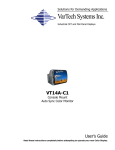
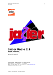
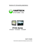
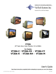
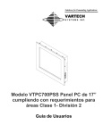
Solutions for Demanding Applications
VarTech Systems Inc.
Industrial CRT and Flat Panel Displays
Color TFT LCD Monitor
VT181R2 · VT181RH2 · VT181M2
User’s Guide
Read these instructions completely before attempting to operate your new Color Display.
Table Of Contents
Page
Section 1
Page
Section 4
Introduction
1
1.1 About LCD Monitors
1
1.2 Product Safety Precautions
2
Troubleshooting Tips
10
Section 5
Cleaning & Maintenance
11
Section 2
Display Setup
3
Section 6
2.1 Instructions
3
Mechanical Drawings
12
2.2 Repacking
3
18.1” Low Scan Tabletop Mechanical
13
2.3 Signal Connections
4
18.1” Low Scan Rack Mount Mechanical
14
18.1” Honeywell Configured Rack Mount Mechanical
15
Section 3
Getting Started
5
Section 7
3.1 Operating Instructions
5
Display Specifications
3.2 Adjustment Procedure
6
3.3 Other OSD Functions
7
3.4 Adjusting for more than one monitor
7
3.5 Frequency & Frequency Fine
8
3.6 Signal Formats
9
16
Section
1
INTRODUCTION
About LCD Monitors
1.1 What you gain by using an LCD monitor in your industrial controls
LCDs
are the future of display technology. CRTs although they have
dropped in cost significantly, do not offer the performance, reliability,
and mounting options available with LCDs. LCD monitors consist
primarily of an LCD, Video Board and a Back Light video. The LCD
determines to a large extent the viewing angle, brightness and contrast. Beyond that it is the
function of the video board which converts the analog RGB (Red, Green, Blue) signals from a
standard video card to a high quality, digital RGB that the LCD can display.
Recently the video card has taken on a new role. It is the responsibility of this device to “scale” a
particular video resolution to the “native” resolution of the LCD. Simply, consider that a computer is
putting out a VGA [640x480] resolution signal, yet the LCD that is connected is an XGA
[1024x768] display. The displayed picture would be in the center 1/3 of the LCD. With the
introduction of the scaling engine. The converter will mathematically recalculate the 640x480 to
1024x768. This may sound simple but it is in fact a complex algorithm that adjusts for different
aspect ratios and pixel alignment, essentially smoothing text and graphics to produce a picture
that is pleasant to the eye.
All Vartech displays from 12.1” (800x600) to 23.1 (1600x1200) incorporate scaling engines in the
converter card.
1
1.2
Product Safety Precautions
⇒
Ensure that sufficient space is available around the display to provide the circulation
necessary for cooling.
⇒
Ensure that the ambient air temperature will not exceed the specified maximum
temperature.
⇒
Do not attempt to service this display yourself. The rear chassis has a seal so that non
qualified personal will not expose themselves to dangerous voltages or other risks.
⇒
To protect from electrical shock, unplug the display power supply from the wall before
moving.
⇒
Do not expose the display to direct sunlight or heat.
⇒
Do not use this display near water
⇒
Do not place any heavy objects on the power cords. Damage may cause electrical shock.
⇒
Unplug the power supply from the wall or unit if one of the following conditions exists.
⇒ Power cord or plug is damaged or frayed
⇒ Liquid is spilled into the display or the display is exposed to rain or water.
⇒ The display does not operate normally when the operating instructions are
followed.
⇒ The display has been dropped or the enclosure has been damaged.
⇒ The display exhibits a distinct change in performance, indicating a need for
service.
2
Section
DISPLAY SETUP
2
2.1 INSTALLATION
Do not allow anything to rest upon or roll over the power cord, and do not place
the display where the power cord is subject to damage.
Do not use this display near water such as near a sink, in a wet location where there is
standing water. Displays are provided with ventilation openings in the cabinet to allow the
release of heat generated during operation. If these openings are blocked, built-up heat can
cause failures which may result in a fire hazard.
Therefore, NEVER:
♦ Block any ventilation slots.
♦ Place the display in a built-in enclosure unless proper ventilation is provided.
♦ Cover the openings with cloth or other material.
♦ Place the display near or over a heat source.
Do not rub or strike the Active Matrix LCD with anything hard as this may scratch,
mar, or damage the Active Matrix LCD permanently.
Do not press the LCD screen with your finger for a long time as this may cause
some afterimages.
Some dot defects may appear as Red, Green or Blue spots on the screen.
However, this will have no impact or effect on the display performance.
If possible, use the recommended resolution to obtain the best image quality for
your LCD display. If used under any mode except the recommended resolution,
some scaled or processed images may appear on the screen. However, this is
characteristic of the fixed-resolution LCD panel.
2.2 REPACKING
Do not throw away the carton and packing materials. They make an ideal
container in which to transport the unit. When shipping the unit to another
location, repack it in its original material.
3
2.3 Signal Connections Cont.
The power and signal inputs to the monitor are located on the rear of the unit.
SIGNAL INPUT
Standard hi-density 15way video connection
POWER INPUT
Connector: 3 pin circular locking type
DIN41524
Pin Number
Function
1
Red video
2
Green Video
3
Blue Video
4
Not connected
5
Not connected
6
Red ground
7
Green ground
8
Blue ground
9
Not connected
10
Sync ground
11
Not connected
12
Not connected
13
Horizontal sync
14
Vertical sync
15
Not Connected
Pin Number
Function
1
+12VDC
2
0V
3
15-30VDC
2
3
1
COMMS
This connector is used in the factory or by service
technician to program the monitor with setup
information. The User should not attempt to use
this connector.
TTL Input
This 9 way D connector allows monitor to operate with TTL
video from EGA/CGA PC’s or other TTL graphics cards.
Default factory setting is for 6 bit video. Factory set jumpers
can select 3 or 4 bit video if required.
Pin
Number
Function
3 bit video
4bit video
6 bit video
1
GND (0v) GND (0v) GND (0v)
2
NC
NC
Red Intensity
3
Red
Red
Red
4
Green
Green
Green
5
Blue
Blue
Blue
6
NC
NC
Green Intensity
7
NC
NC
Blue Intensity
8
Horizontal Sync
Horizontal Sync
Horizontal Sync
9
Vertical Sync
Vertical Sync
Vertical Sync
4
R.G.B.H.V.
BNC inputs for analog signals
These inputs allow monitor to
be used with BNC connector
leads with
3 wire operation
(sync on green)
4 wire operation
(composite syncs)
5 wire operation
(separate H,V syncs)
R,G,B inputs have 75Ω input
resistance. H,V inputs must be
TTL level inputs.
Section
GETTING STARTED
3
3.1 OPERATING INSTRUCTIONS
The monitor must be connected to a suitable DC power source and video signal. The
monitor will switch on as soon as the power is applied and a picture will be displayed.
Basic User Controls
Adjustments to the picture can be made by means of the push button controls on the front of
the monitor.
The → & ← buttons control the contrast of the display. If either of these buttons is
pressed then the monitor displays a banner that shows the value of contrast. Further
pressing of the buttons will then adjust the contrast.
The ↑ & ↓ buttons control the video brightness of the display.. If either of these buttons is
pressed then the monitor dipslays a banner that shows the brightness. Further pressing of
the buttons will then adjust the brightness.
The two left hand buttons control the illumination of the display backlights.
These basic user controls are the only adjustemnts that can be made when the OSD lockout
function is enabled.
Advanced OSD Controls
Pressing menu button activates the monitor’s
main set-up controls. When this is done the
monitor displays a menu of adjustments. The
↑ & ↓ buttons allow selection of which item
to adjust. The → & ← buttons adjust the
highlighted item.
OSD Information Banner
Information about the input signal is displayed at the bottom of the OSD. The values on the
left hand side are the Horizontal Rate (48.40kHz) and the Vertical Rate (59.8Hz).
On the right hand side the values are the active video size that the current video made is
based upon. This will be either in WHITE—indicating that the current scaling is based on
factory preset standard mode, or CYAN—indicating that the scaling has been calculated by
the monitor, either automatically or directed by the Reset Modes menu item. These values
do not change and are only for reference.
5
3.2 PROCEDURE FOR PICTURE ADJUSTMENT
Each value that is adjusted is automatically saved when the highlighted line is moved, the
only exception is when the RESTORE function is used.
If at any time the monitor cannot accept the new settings it will recall the previous good
values.
Step 1
Move picture so the
top left hand corner
is positioned
correctly.
The top left hand of the picture needs to be 2 to 3mm from the
corner of the screen. Use the ↑ & ↓ buttons untill HORIZONTAL
POS is highlighted. Then use the → & ← buttons to move the
pictures horizontally.
Next use the ↑ & ↓ buttons until VERTICAL POS is highlighted.
Then use the → & ← buttons to move the picture vertically.
Step 2
Make picture the
correct width.
Use the ↑ & ↓ buttons until HORIZONTAL SIZE is highlighted. Then
use the → & ← buttons to adjust the picture to correct width. There
should be a 2 to 3mm gap at each side between the picture and the
edge of the screen.
Step 3
Adjust the
Frequency and
Frequency Fine.
Correct Frequency and Frequency Fine adjustment are vital to
obtain a clear image. See Appendix A for an explanation of
principles involved, before making these adjustments.
Use the ↑ & ↓ buttons until FRENQUENCY is highlighted. Then use
the → & ← buttons to adjust it so that any noise lines move further
apart from each other. Adjust until there are no noise lines seen.
Use the ↑ & ↓ buttons until FRENQUENCY FINE is highlighted.
Then use the → & ← buttons to adjust to make the display
characters appear as bright, sharp and noise free as possible.
Step 4
Adjust the Vertical
Size.
The monitor must make many calculations when this control is used:
These take several seconds. During this time the display is unstable
and the OSD will flash.
If the value of Vertical size is increased the display gets smaller and
vice-versa. This is because the displayed value of vertical size is
the number of lines of video that are being stretched to fit on the
screen.
If you try to change the vertical size by a large amount in one step,
the monitor may be unable to make this change. It will be forced to
restore the display to its previous height. Always change the size in
steps of 2 or 4.
There is a 0.5 second time delay from when the first key press is
detected and when the monitor will attempt to set-up the monitor to
the new value of vertical size.
Step 5
Repeat the
Procedure.
Repeat the procedure fro any other video signals that the monitor is
used with.
Step 6
Exit the menu and
lock the OSD.
When the monitor is set correctly for its intended application, it is
recommended to enable OSD lockout function to prevent accidental
adjustment by casual user.
To lock the OSD: When there is no OSD displayed, press and hold
down the Menu button. The OSD will appear. Keep the button
down for several seconds until the OSD disappears.
To unlock the OSD: Press and hold down the Menu button. Keep
the button down for several seconds until the OSD appears.
When OSD is locked only the Basic User Controls are functional.
6
3.3 OTHER OSD FUNCTIONS
Restore
Use this function if adjustments mad to monitor need to be undone. This returns the monitor
to the state when the OSD was STARTED.
Use the ↑ & ↓ buttons until RESTORE is highlighted. Then use the → & ← buttons to
undo adjustments made to the monitor.
Reset Mode(s)
This has four options that are selectable as detailed below.
Use the ↑ & ↓ buttons until RESET MODE(S) is highlighted. Then use the → or ←
buttons to swithch between NO-YES - ALL - NEW.
These operate as follows:
NO - No action taken
YES - Resets currently detected video mod to its factory default setting.
ALL - Resets the complete monitor to its factory default settings.
NEW - Forces the monitor to automatically analyse the incoming video and set-up
the monitor to display a stable picture. This will overwrite the current values for
the video picture. A “PLEASE WAIT…” banner will be shown during this set-up
period. The values decided upon are based on the assumption that the video
aspect ration is 4:3. This can be changed as described above.
When the selection has been made, use the ↑ & ↓ buttons until EXIT is highlighted. Then
use the → & ← buttons to exit the OSD.
Exit
Use the ↑ & ↓ buttons until EXIT is highlighted. Then use the → or ← buttons to close the
OSD.
3.4 ADJUSTING MORE THAN ONE MONITOR
The procedure for setting a monitor is quite complex. If there are more monitors t be used
on identical systems, then this can be done more easily by manually copying the OSD
values from the first monitor.
These values can be set in subsequent
monitors to speed up their adjustment to the
same signals.
FACTORY SETTING SERVICE
VarTech can offer a programming service for the next deliveries. The values that you have
set up on a sample monitor can be pre-loaded in the factory.
The monitors will then work with your system with minimal adjustments.
7
3.5 Frequency & Frequency Fine
Adjustment of TFT monitors
The Video signal is made up of pixels. These are generated in the video generator (process
controller, PC, etc.) A crystal oscillator controls the rate at which the pixels are generated: this is
called the Dot Clock.
When the TFT monitor receives the video signal it must convert it back to it’s individual pixels in digital
form. To do this it must sample the video at the same rate as the dot clock.
When the frequency control is adjusted the monitor is changing the rate at which the video is sampled.
Each press of the frequency control changes the sample rate by one pixel per line.
The visual effect on the monitor screen of incorrect frequency adjustment is that there are vertical
bands of darkened or noisy pixels running down the screen. The greater the frequency error, then
the more bands there are. If the frequency value is wrong by two pixels, then two noisy bands will be
seen. If the value is wrong by 100 pixels then 100 noisy bands will be seen. Strangely, a picture that
has the frequency wrong by a very large amount can actually appear better than the one where the
frequency is only slightly wrong.
The actual content of the picture also has a big effect on how easy it is to see the noise bands. To set
the frequency easily, it is best to display a picture that has a large number of individual pixels
displayed—a screen of “░░░░“ will be very good for helping to make the adjustment, while “████ “
or “
“ will completely hide the noise bars. In the practice it is not always possible to control the
characters like this so adjustment has to be made with pages of text etc.
Figure 1: Correct Frequency
Picture 2: Incorrect Frequency
A Windows Shutdown screen contains a large amount of the “░░░░“ type of video so it is very
good for seeing the effect of the frequency setting. Picture 1 shows the shutdown screen with
frequency correctly set.
Picture 2 picture had six vertical dark bands due to incorrect frequency.
This figure shows what a single bright pixel
looks like in the video signal. The pixel does
not have vertical sides and the exact start
time of the pixel is uncertain. If the monitor
samples the pixel at “B”, then “A” then the
uncertainty of the pixels start time and the
slope of he pixel edge will combine to make
the pixel appear noisy and dark on the
screen.
It is the frequency fine control that lets the monitor be adjusted so that the sample is taken at B instead of A.
8
3.6
SIGNAL FORMATS
These signals are currently factory programmed into the monitor
Resolution
V Rate
H Rate
Syncs
H
V
Application
640 x 350
70Hz
31.475kHz
VGA
640 x 400
70Hz
31.475kHz
VGA
640 x 480
60Hz
31.475kHz
VGA
1024 x 384
40Hz
16.67kHz
IECC Railway Signaling
1024 x 768
60Hz
48.40kHz
XGA
1280 x 1024
60Hz
63.98kHz
SXGA
640 x 384
50Hz
20.65kHz
ABB Mod300
640 x 384
60Hz
24.78kHz
ABB Mod300
800 x 600
56Hz
35.21kHz
SVGA
604 x 240
60Hz
15.72kHz
Honeywell TDC2000
662 x 315
50Hz
17.86kHz
Honeywell PMX (see note 1)
810 x 246
60Hz
15.63kHz
Honeywell TDC3000 EOS
650 x 450
66Hz
31.25kHz
Honeywell TDC3000 EPDG2
560 x 275
50Hz
15.63kHz
Confidential
640 x 200
60Hz
15.7kHz
+
+
CGA
640 x 350
60Hz
21.83kHz
+
+
EGA
714 x 288
50Hz
15.625kHz
508 x 338
50Hz
17.85kHz
+
-
Aydin 5215 (see note 2)
508 x 240
60Hz
15.72kHz
+
+
Aydin 5215 (see note 2)
564 x 304
50Hz
16.10kHz
564 x 240
60Hz
15.72kHz
1280 x 1024
75Hz
80.00kHz
SXGA
1024 x 328
50Hz
27.03kHz
Confidential
1152 x 864
75Hz
67.50kHz
Apple Mac
640 x 480
50Hz
208.92kHz
Confidential
CCIR
Aydin 5215 (see note 2)
+
-
Aydin 5215 (see note 2)
Note 1:
Honeywell PMX has video pedestal that requires special model.
Note 2:
Aydin5215 generator requires 180ohm resistor placed in series with each R,G,B lead.
9
Section
4
TROUBLESHOOTING GUIDE
TROUBLESHOOTING GUIDE
Trouble
Troubleshooting Tip
Unable to set Vertical Size
The Vertical Size value is limited by what values are set for
Frequency and Horizontal size.
Not all video modes can be shown full screen.
Sometimes the vertical size will have to be small.
Cannot Set Correct Frequency
On some systems there are no pictures available that make
frequency setting easy. This can make it very hard to see
what is happening on the screen.
Tip One:
Adjust the frequency fine.
When this adjusted any vertical frequency bands on the
screen will move. This makes them much easier to see
- especially if they have been hiding in blank parts of
the display.
Tip Two:
If there are any specifications for the system then you
may be able to calculate what the approximate value of
frequency should be.
The frequency value to set on the monitor is the
TOTAL number of pixels in one horizontal period.
Example:If the Horizontal Line Frequency = 25kHz
Dot Clock = 10mHz
Then frequency = 10mHz
·/· 25khz
= 400
OR: If 80 characters per line an 12 x 16 character cell
And 35us horizontal active time
And 40us horizontal scanning time
Then frequency = 80 x 12 x 35 / 40 = 840
Using calculations like this should make it easy to preset the
frequency into roughly the correct range, but further
adjustment normally will be needed for the last few percent.
Menu button does not work
The OSD lockout feature is enabled.
Hold menu button in for several seconds.
If these tips do not solve your problem, contact VarTech Systems Customer Service Support.
10
Section
5
CLEANING AND MAINTANENCE
Cleaning
Occasionally clean the display panel and cabinet with a soft cloth dampened (not soaked) with a
mild (non-abrasive) glass cleaner. Keep turning a fresh side of the cloth toward the screen surface to
avoid scratching it with accumulated grit.
Note:
The solvent should be applied only to the cloth, and not directly on the monitor screen.
Do not use paper products as they may scratch the surface. To minimize the risk of abrasion, allow
the screen to stand dry.
Special care should be taken when cleaning a touch screen or polycarbonate shield that is installed
over the screen. Abrasive and certain chemical cleaners can easily damage the surface.
Never use alcoholic or ammoniac cleaners to clean the polycarbonate shield or a touch screen.
Note:
For best results cleaning a monitor with the optional antireflective tempered glass display shield, a
solution of denatured alcohol is recommended to thoroughly clean the display.
Replacing a Line Cord
To avoid shock and fire hazards, the monitor’s power cord should be replaced if the insulation
becomes broken or if it develops a loose internal connection.
Other Maintenance
Qualified service personnel should perform all maintenance, except for the power cord replacement
described above.
11
Section
6
MOUNTING INSTRUCTIONS
Mechanical Drawings
Model
Description
Page(s)
VT181M2
18.1” Low Scan Tabletop Mechanical Drawing
13
VT181R2
18.1” Low Scan Rack Mount Mechanical Drawing
14
VT181RH2
18.1” Honeywell Configured Rack Mount Mechanical Drawing
15
12
Section
7
SPECIFICATIONS
ENGINEERING SPECIFICATIONS
Input voltage:
90-264VAC Universal
Power consumption:
60W max
Display area
14.135” x 11.310”
359.02mm x 287.27mm
Pixel Format
1280 x 1024
Signal formats
640 x 480 pixels, 800 x 600 pixels,
1024 X 768 pixels,1280 X 1024 pixels
ABB MOD 300
Horizontal scan
15-70kHz
Vertical scan
56-75Hz
Clock rate
135MHz max
Viewing angle(CR>5)
±70° Horizontal
+70°, -40° Vertical
Contrast ratio
300: 1
Brightness
200 cd/m2 typ
Colors Displayed
16M
Video Input
Analog RGB 0.7V p-p 75Ω or
TTL > 2.75V p-p DB9(F)
Sync
Separate H&V (TTL pos. or neg.) or
Composite (TTL pos. or neg.) or
Sync on Green (0.3V p-p, neg.)
Video Input Connector
HD15(F), 5BNC, DB9(F)
Temperature
Operating: 0 to 45º
Storage: -20 to 60º
Humidity
Operating: 10 to 95% NC
Storage: 10 to 95% NC
Altitude
Operating: up to 10,000 ft
Storage: up to 40,000 ft
16
VARTECH SYSTEMS
HEADQUARTERS
11529 Sun Belt Ct.
Baton Rouge, Louisiana 70809
Toll-Free: 800.223.8050
International Phone: 001.225.298.0300
Fax: 225.297.2440
E-mail: [email protected]
www.vartechsystems.com
150-026-005
7.16.03