1
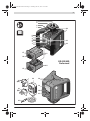
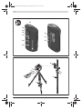
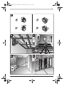
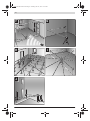
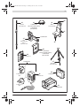
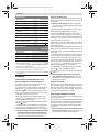
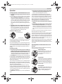
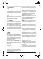
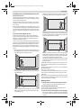
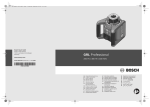
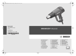
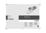
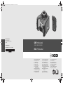
OBJ_BUCH-757-007.book Page 1 Tuesday, June 21, 2011 10:14 AM Robert Bosch GmbH Power Tools Division 70745 Leinfelden-Echterdingen Germany GRL Professional www.bosch-pt.com 250 HV | 300 HV | 300 HVG 1 619 929 J21 (2011.06) T / 310 UNI RC 1 Professional de en fr es pt it nl Originalbetriebsanleitung Original instructions Notice originale Manual original Manual original Istruzioni originali Oorspronkelijke gebruiksaanwijzing da Original brugsanvisning sv Bruksanvisning i original no Original driftsinstruks fi Alkuperäiset ohjeet el tr pl cs sk hu ru Ðñùôüôõðï ïäçãéþí ÷ñÞóçò Orijinal işletme talimat Instrukcja oryginalna Původní návod k používání Pôvodný návod na použitie Eredeti használati utasítás Îðèãèíàëüíîå ðóêîâîäñòâî ïî ýêñïëóàòàöèè uk Îðèã³íàëüíà ³íñòðóêö³ÿ ç åêñïëóàòàö³¿ ro Instrucţiuni originale bg Îðèãèíàëíà èíñòðóêöèÿ sr sl hr et lv lt ar fa Originalno uputstvo za rad Izvirna navodila Originalne upute za rad Algupärane kasutusjuhend Instrukcijas oriģinālvalodā Originali instrukcija ΔϴϠλϷ ϞϴϐθΘϟ ΕΎϤϴϠόΗ ̶Ϡλ έΎ̯ ίήσ ̵ΎϤϨϫέ OBJ_BUCH-757-007.book Page 3 Tuesday, June 21, 2011 10:16 AM |3 9 8 8 7 10 7 6 5 4 3 2 1 11 12 17 13 16 14 GRL 300 HVG Professional 15 23 (UK) 22 18 19 20 IEC ass 3Rct ey IATIO 6 lasee expoN < 5 0825 r prod sure mW -1:2 uct , 5 00 32 7-0 nm 3 Av LASE oid R Cl dire RAD 21 APLAS ER ER TU RE 23 (EU) 24 Bosch Power Tools 1 619 929 J21 | (21.6.11) OBJ_BUCH-757-007.book Page 4 Tuesday, June 21, 2011 10:16 AM 4| 31 30 29 28 32 27 33 34 26 25 35 36 37 1 619 929 J21 | (21.6.11) Bosch Power Tools OBJ_BUCH-757-007.book Page 5 Tuesday, June 21, 2011 10:16 AM |5 A B C D E Bosch Power Tools 1 619 929 J21 | (21.6.11) OBJ_BUCH-757-007.book Page 6 Tuesday, June 21, 2011 10:16 AM 6| F G H I 10 0 m 10 0m J 1 619 929 J21 | (21.6.11) Bosch Power Tools OBJ_BUCH-757-007.book Page 7 Tuesday, June 21, 2011 10:16 AM |7 40 36 38 39 GR 240: 0 601 094 100 1 608 M00 05B (GRL 250 HV/GRL 300 HV)/ 1 608 M00 05J (GRL 300 HVG) WM 4: 0 601 092 400 41 1 608 M00 05A 35 LR 1: 0 601 015 400 LR 1 G: 0 601 069 700 42 43 44 2 610 A01 267 1 608 M00 05C (GRL 250 HV/GRL 300 HV)/ 1 608 M00 05K (GRL 300 HVG) 37 1 608 M00 05E BT 300 HD: 0 601 091 400 2 610 A13 717 (UK) 2 610 A13 716 (EU) Bosch Power Tools 22 45 1 608 M00 05F 2 610 A13 782 13 1 608 M00 05G 1 619 929 J21 | (21.6.11) OBJ_BUCH-757-007.book Page 18 Tuesday, June 21, 2011 10:16 AM 18 | English www.powertool-portal.de, das Internetportal für Handwerker und Heimwerker. www.ewbc.de, der Informations-Pool für Handwerk und Ausbildung. Deutschland Robert Bosch GmbH Servicezentrum Elektrowerkzeuge Zur Luhne 2 37589 Kalefeld – Willershausen Tel. Kundendienst: +49 (1805) 70 74 10* Fax: +49 (1805) 70 74 11* (*Festnetzpreis 14 ct/min, höchstens 42 ct/min aus Mobilfunknetzen) E-Mail: [email protected] Tel. Kundenberatung: +49 (1803) 33 57 99 (Festnetzpreis 9 ct/min, höchstens 42 ct/min aus Mobilfunknetzen) Fax: +49 (711) 7 58 19 30 E-Mail: [email protected] Österreich Tel.: +43 (01) 7 97 22 20 10 Fax: +43 (01) 7 97 22 20 11 E-Mail: [email protected] Schweiz Tel.: +41 (044) 8 47 15 11 Fax: +41 (044) 8 47 15 51 Luxemburg Tel.: +32 (070) 22 55 65 Fax: +32 (070) 22 55 75 E-Mail: [email protected] Entsorgung Rotationslaser, Ladegerät, Fernbedienung, Akkus, Zubehör und Verpackungen sollen einer umweltgerechten Wiederverwertung zugeführt werden. Werfen Sie Rotationslaser, Ladegerät, Fernbedienung und Akkus/Batterien nicht in den Hausmüll! Nur für EU-Länder: Gemäß der europäischen Richtlinie 2002/96/EG müssen nicht mehr gebrauchsfähige Elektrogeräte und gemäß der europäischen Richtlinie 2006/66/EG müssen defekte oder verbrauchte Akkus/Batterien getrennt gesammelt und einer umweltgerechten Wiederverwendung zugeführt werden. Nicht mehr gebrauchsfähige Akkus/Batterien können direkt abgegeben werden bei: Deutschland Recyclingzentrum Elektrowerkzeuge Osteroder Landstraße 3 37589 Kalefeld Schweiz Batrec AG 3752 Wimmis BE 1 619 929 J21 | (21.6.11) Akkus/Batterien: Ni-MH: Nickel-Metallhydrid Änderungen vorbehalten. English Safety Notes Rotational Laser Level Working safely with the measuring tool is possible only when the operating and safety information are read completely and the instructions contained therein are strictly followed. Never make warning labels on the measuring tool unrecognisable. SAVE THESE INSTRUCTIONS. f Caution – The use of other operating or adjusting equipment or the application of other processing methods than those mentioned here, can lead to dangerous radiation exposure. f Do not use the laser viewing glasses as safety goggles. The laser viewing glasses are used for improved visualisation of the laser beam, but they do not protect against laser radiation. f Do not use the laser viewing glasses as sun glasses or in traffic. The laser viewing glasses do not afford complete UV protection and reduce colour perception. f Have the measuring tool repaired only through qualified specialists using original spare parts. This ensures that the safety of the measuring tool is maintained. f Do not operate the measuring tool in explosive environments, such as in the presence of flammable liquids, gases or dusts. Sparks can be created in the measuring tool which may ignite the dust or fumes. f Do not open the battery pack. Danger of short-circuiting. Protect the battery pack against heat, e.g., against continuous intense sunlight, fire, water, and moisture. Danger of explosion. f Keep the battery pack not being used away from paper clips, coins, keys, nails, screws or other small metal objects that can make a connection from one terminal to another. Shorting the battery terminals together may cause burns or a fire. f Under abusive conditions, liquid may be ejected from the battery pack; avoid contact. If contact accidentally occurs, flush with water. If liquid contacts eyes, additionally seek medical help. Liquid ejected from the battery may cause irritations or burns. Bosch Power Tools OBJ_BUCH-757-007.book Page 19 Tuesday, June 21, 2011 10:16 AM English | 19 f Charge the battery pack only with the battery charger specified in these operating instructions. A charger that is suitable for one type of battery pack may create a risk of fire when used with another battery pack. f Use only original Bosch battery packs with the voltage listed on the nameplate of your measuring tool. When using other battery packs, e.g. imitations, reconditioned battery packs or other brands, there is danger of injury as well as property damage through exploding battery packs. Keep the laser target plate 43 and the ceiling measurement plate 44 away from cardiac pacemakers. The magnets on the laser target plate and on the ceiling measurement plate generate a field that can impair the function of cardiac pacemakers. f Keep the laser target plate 43 and the ceiling measurement plate 44 away from magnetic data medium and magnetically-sensitive equipment. The effect of the magnets on the laser target plate and on the ceiling measurement plate can lead to irreversible data loss. GRL 300 HV/GRL 300 HVG f The measuring tool is provided with two warning labels in English (marked with number 20 and 21 in the representation of the measuring tool on the graphics page). GRL 250 HV f The measuring tool is provided with a warning label in English (marked with number 20 in the representation of the measuring tool on the graphics page). IEC 60825-1:2007-03 <1mW, 635 nm f Do not direct the laser beam at persons or animals and do not stare into the laser beam yourself. This measuring tool produces laser class 2 laser radiation according to IEC 60825-1. This can lead to persons being blinded. f Do not allow children to use the laser measuring tool without supervision. They could unintentionally blind other persons or themselves. Bosch Power Tools f Do not direct the laser beam at persons or animals and do not look into the laser beam yourself. This measuring tool generates laser radiation from class 3R according to IEC 60825-1. Looking directly into the laser beam – even from a greater distance cause damages to the eyes. f Avoid reflection of the laser beam on smooth surfaces such as windows or mirrors. A reflected laser beam can also cause damage to the eye. f The measuring tool should be operated only by persons that are familiar with the handling of laser devices. According to EN 60825-1, this includes, among other things, the knowledge about the biological effects of the laser to the eyes and the skin as well as the correct usage of laser protection devices in order to avoid dangers. f Always set up the measuring tool in such a manner that the laser beams run far above or below eye level. This ensures that damage to the eyes will not occur. f Mark the area in which the measuring tool is being used with suitable laser warning labels. This prevents persons not involved from accessing the danger area. f Do not store the measuring tool at locations, to which unauthorised persons have access. Persons not familiar with the operation of the measuring tool can cause harm to themselves and to others. 1 619 929 J21 | (21.6.11) OBJ_BUCH-757-007.book Page 20 Tuesday, June 21, 2011 10:16 AM 20 | English f When using a class 3R measuring tool, observe possible national regulations. Non-observance of these regulations can lead to injury. f Make sure that the area of laser radiation is monitored or shielded. The limitation of laser radiation to controlled areas prevents eye damage to persons not involved. Remote control Battery Charger f Have the remote control repaired only through a qualified repair person and only using identical replacement parts. This will ensure that the functionality of the remote control is maintained. f Do not operate the remote control in explosive atmospheres, such as in the presence of flammable liquids, gases or dusts. Sparks can be created in the remote control which may ignite the dust or fumes. Read all safety warnings and all instructions. Failure to follow the warnings and instructions may result in electric shock, fire and/or serious injury. Keep the battery charger away from rain or moisture. Penetration of water in the battery charger increases the risk of an electric shock. f Do not charge other batteries with the battery charger. The battery charger is only suitable for charging the Bosch battery/battery pack inserted in the rotational laser level. Danger of fire and explosion when charging other batteries/battery packs. f Keep the battery charger clean. Contamination can lead to danger of an electric shock. f Before each use, check the battery charger, cable and plug. If damage is detected, do not use the battery charger. Never open the battery charger yourself. Have repairs performed only by a qualified technician and only using original spare parts. Damaged battery chargers, cables and plugs increase the risk of an electric shock. f Do not operate the battery charger on easily inflammable surfaces (e.g., paper, textiles, etc.) or surroundings. The heating of the battery charger during the charging process can pose a fire hazard. f Under abusive conditions, liquid may be ejected from the battery pack; avoid contact. If contact accidentally occurs, flush with water. If liquid contacts eyes, additionally seek medical help. Liquid ejected from the battery may cause irritations or burns. f Supervise children. This will ensure that children do not play with the charger. f Children or persons that owing to their physical, sensory or mental limitations or to their lack of experience or knowledge, are not capable of securely operating the charger, may only use this charger under supervision or after having been instructed by a responsible person. Otherwise, there is danger of operating errors and injuries. f Products sold in GB only: Your product is fitted with a BS 1363/A approved electric plug with internal fuse (ASTA approved to BS 1362). If the plug is not suitable for your socket outlets, it should be cut off and an appropriate plug fitted in its place by an authorised customer service agent. The replacement plug should have the same fuse rating as the original plug. The severed plug must be disposed of to avoid a possible shock hazard and should never be inserted into a mains socket elsewhere. 1 619 929 J21 | (21.6.11) Read and observe all instructions. SAVE THESE INSTRUCTIONS FOR FUTURE REFERENCE. Product Description and Specifications Intended Use Rotational Laser Level The measuring tool is intended for determining and checking precise horizontal partitions, vertical lines, building lines and plumb points. The measuring tool is suitable for indoor and outdoor use. Remote control The remote control is intended for controlling rotational laser levels in indoor and outdoor use. Product Features The numbering of the product features refers to the illustration of the rotational laser level, battery charger and remote control on the graphics page. Rotational laser level/Battery charger 1 Shock-warning indicator 2 Shock-warning button 3 Automatic levelling indicator 4 On/Off button of the rotational laser level 5 Button for rotational operation and selection of the rotation speed 6 Variable laser beam 7 Reception lens for remote control 8 Exit opening for laser beam 9 Plumb beam 10 Rotation head 11 Button for line operation and line length selection 12 Charge-control indicator 13 Battery pack* 14 Battery compartment 15 Locking knob of the battery compartment 16 Locking knob of the battery pack* 17 Socket for charge connector* 18 Tripod mount 5/8" 19 Serial number of the rotational laser level Bosch Power Tools OBJ_BUCH-757-007.book Page 21 Tuesday, June 21, 2011 10:16 AM English | 21 20 Laser warning label 21 Warning label, laser radiation exit opening (GRL 300 HV/GRL 300 HVG) 22 Battery charger* 23 Mains plug of the battery charger* 24 Charge connector* 33 Latch of battery lid 34 Battery lid Remote control 25 Button on the remote control for rotation operation and selection of rotational speed 26 Button on the remote control for line operation and selection of line length 27 Shock-warning reset button 28 Button for “rotation in clockwise direction” 29 Button for “rotation in anticlockwise direction” 30 Operation indicator 31 Outlet opening for infra-red beam 32 Serial number Accessories/Spare parts 35 Laser receiver* 36 Construction laser measuring rod* 37 Tripod* 38 Laser viewing glasses* 39 Wall mount/alignment unit* 40 Fastening screw of the wall mount* 41 Screw of the alignment unit* 42 5/8" screw on wall mount* 43 Laser target plate* 44 Ceiling measurement plate* 45 Case * The accessories illustrated or described are not included as standard delivery. Technical Data Rotational Laser Level Article number Working range (radius) 1) – without laser receiver, approx. – with laser receiver, approx. Levelling Accuracy 1) 2) Self-levelling range, typically Levelling duration, typically Rotational speed Aperture angle for line operation Operating temperature Storage temperature Relative air humidity, max. Laser class Laser type Laser beam Ø at the exit opening, approx. 1) Tripod mount (horizontal) Batteries (NiMH) Batteries (alkali-manganese) Operating life time, approx. – Batteries (NiMH) – Batteries (alkali-manganese) Weight according to EPTA-Procedure 01/2003 Dimensions (length x width x height) Degree of protection GRL 250 HV Professional 3 601 K61 60. GRL 300 HV Professional 3 601 K61 50. GRL 300 HVG Professional 3 601 K61 70. 30 m 125 m ±0.1 mm/m ±8 % (±5°) 15 s 150/300/600 min-1 10/25/50° –10...+50 °C –20...+70 °C 90 % 2 635 nm, <1 mW 30 m 150 m ±0.1 mm/m ±8 % (±5°) 15 s 150/300/600 min-1 10/25/50° –10...+50 °C –20...+70 °C 90 % 3R 635 nm, <5 mW 50 m 150 m ±0.1 mm/m ±8 % (±5°) 15 s 150/300/600 min-1 10/25/50° 0...+40 °C –20...+70 °C 90 % 3R 532 nm, <5 mW 5 mm 5 mm 5 mm 5/8"-11 5/8"-11 5/8"-11 2 x 1.2 V HR20 (D) (9 Ah) 2 x 1.2 V HR20 (D) (9 Ah) 2 x 1.2 V HR20 (D) (9 Ah) 2 x 1.5 V LR20 (D) 2 x 1.5 V LR20 (D) 2 x 1.5 V LR20 (D) 40 h 60 h 30 h 50 h 20 h 30 h 1.8 kg 190 x 180 x 170 mm IP 54 (dust and splash water protected) 1.8 kg 190 x 180 x 170 mm IP 54 (dust and splash water protected) 1.8 kg 190 x 180 x 170 mm IP 54 (dust and splash water protected) 1) at 20 °C 2) alongside the axes Please observe the article number on the type plate of your rotational laser level. The trade names of individual rotational laser levels may vary. For clear identification of your rotational laser level, see the serial number 19 on the type plate. Bosch Power Tools 1 619 929 J21 | (21.6.11) OBJ_BUCH-757-007.book Page 22 Tuesday, June 21, 2011 10:16 AM 22 | English Battery Charger Article number Rated voltage Frequency Output voltage Charging current Allowable charging temperature range Charging time Number of battery cells Rated voltage (per battery cell) Weight according to EPTA-Procedure 01/2003 Protection class Remote control Article number Working range 3) Operating temperature Storage temperature Battery Weight according to EPTA-Procedure 01/2003 V~ Hz V= A 2 610 A13 782 100–240 50/60 7.5 1.0 °C h V= kg 0–45 14 2 1.2 0.2 /II RC 1 Professional 3 601 K69 900 30 m –10 °C...+50 °C –20 °C...+70 °C 1 x 1.5 V LR06 (AA) 69 g 3) The working range can be decreased by unfavourable environmental conditions (e.g. direct sun irradiation). Please observe the article number on the type plate of your remote control. The trade names of individual remote controls may vary. For clear identification of your remote control, see the serial number 32 on the type plate. Assembly Power Supply of the Rotational Laser Level Operation with Batteries/Rechargeable Batteries Using alkali-manganese or rechargeable batteries is recommended for operation of the measuring tool. To open the battery compartment 14, turn the locking knob 15 to position and pull out the battery compartment. When inserting the batteries/rechargeable batteries, pay attention to the correct polarity according to the representation on the inside of the battery compartment. Always replace all batteries/rechargeable batteries at the same time. Do not use different brands or types of batteries/rechargeable batteries together. Shut the battery compartment 14 and turn the locking knob 15 to the position. In case the batteries/rechargeable batteries have been inserted incorrectly, the measuring tool cannot be switched on. Insert the batteries/rechargeable batteries with correct polarity. f Remove the batteries/rechargeable batteries from the measuring tool when not using it for longer periods. When storing for longer periods, the batteries/rechargeable batteries can corrode and discharge themselves. 1 619 929 J21 | (21.6.11) Operation with Battery Pack Charge the battery pack 13 before using for the first time. The battery pack can only be charged with the battery charger 22 intended for it. f Observe the mains voltage! The voltage of the power source must correspond with the data on the type plate of the battery charger. Insert the appropriate mains plug 23 for your mains supply into the battery charger 22 and allow it to engage. Insert the charge plug 24 of the battery charger into the socket connector 17 of the battery pack. Connect the battery charger to the mains supply. Charging the empty battery pack takes approx. 14 h. The battery charger and the battery pack are protected against overcharging. A battery that is new or has not been used for a longer period does not develop its full capacity until after approx. 5 charging/discharging cycles. Do not charge the battery pack 13 each time after using, otherwise its capacity will be reduced. Charge the battery pack only when the charge-control indicator 12 flashes or lights up continuously. A considerably reduced operating period after charging indicates that the battery pack is used up and must be replaced. If the battery pack is empty, the measuring tool can also be operated off of the battery charger 22 when connected to a power supply. Switch the measuring tool off, charge the battery pack for approx. 10 min and then switch the measuring tool on again with the battery charger connected. To change the battery pack 13, turn the locking knob 16 to position and pull out the battery pack 13. Insert a new battery pack and turn the locking knob 16 to the position. f Remove the battery pack from the measuring tool when not using it for longer periods. When storing for longer periods, the rechargeable batteries can corrode and discharge themselves. Charge-control Indicator When the charge-control indicator 12 flashes red for the first time, the measuring tool can still be operated for approx. 2 h. When the charge-control indicator 12 lights up red continuously, measurements are no longer possible. The measuring tool switches off automatically after 1 minute. Power Supply of the Remote Control Using alkali-manganese batteries is recommended for operation of the remote control. To open the battery lid 34, press the latch 33 in the direction of the arrow and remove the battery lid. Insert the battery provided. When inserting, pay attention to the correct polarity according to the representation on the inside of the battery compartment. f Remove the battery from the remote control when not using it for longer periods. When storing for longer periods, the battery can corrode and discharge itself. Bosch Power Tools OBJ_BUCH-757-007.book Page 23 Tuesday, June 21, 2011 10:16 AM English | 23 Operation Starting Operation of the Rotational Laser Level f Protect the measuring tool against moisture and direct sun light. f Do not subject the measuring tool to extreme temperatures or variations in temperature. As an example, do not leave it in vehicles for longer periods. In case of large variations in temperature, allow the measuring tool to adjust to the ambient temperature before putting it into operation. In case of extreme temperatures or variations in temperature, the accuracy of the measuring tool can be impaired. f Avoid heavy impact to or dropping down of the measuring tool. After severe exterior effects to the measuring tool, it is recommended to carry out an accuracy check (see “Levelling Accuracy of the Rotational Laser Level”, page 25) each time before continuing to work. Setting Up the Measuring Tool Horizontal position Vertical position Set up the measuring tool on a sturdy surface in the horizontal or vertical position; mount it on a tripod 37 or to the wall mount with alignment unit 39. Due to the high levelling accuracy, the measuring tool reacts sensitively to ground vibrations and position changes. Therefore, pay attention that the position of the measuring tool is stable in order to avoid operational interruptions due to relevelling. Switching On and Off f Do not direct the laser beam at persons or animals (especially not at their eye level), and do not stare into the laser beam yourself (not even from a distance). Immediately after switching on, the measuring tool sends out the vertical plumb beam 9 and the variable laser beam 6. For switching on the measuring tool, press the On/Off button 4. The indicators 1, 3 and 12 light up briefly. The measuring tool immediately starts the automatic levelling. During the levelling, the levelling indicator 3 lights up green and the laser flashes in point operation. The measuring tool is levelled in as soon as levelling indicator 3 lights up green continuously and the laser beam is steady. After the levelling is completed, the measuring tool automatically starts in rotational operation. With the operating mode buttons 5 and 11, the operating modes can already be specified during levelling in (see “Operating Modes of the Rotational Laser Level”, page 23). In this case, the measuring tool starts in the set operating mode upon completion of levelling in. To switch off the measuring tool, press the On/Off button 4 again. Bosch Power Tools f Do not leave the switched on measuring tool unattended and switch the measuring tool off after use. Other persons could be blinded by the laser beam. To save the batteries, the measuring tool is automatically switched off when not within the self-levelling range for more than 2 h or when the shock warning is actuated for more than 2 h (see “Automatic Levelling of the Rotational Laser Level”, page 24). Reposition the measuring tool and switch it on again. Starting Operation of the Remote Control f Protect the remote control against moisture and direct sunlight. f Do not subject the remote control to extreme temperatures or variations in temperature. As an example, do not leave it in vehicles for longer periods. In case of large variations in temperature, allow the remote control to adjust to the ambient temperature before putting it into operation. The remote control remains ready for operation as long as a battery with sufficient voltage is inserted. Set up the measuring tool in such a manner that the signals of the remote control can directly reach one of the reception lenses 7. When the remote control cannot be pointed directly against a reception lens, the working range is reduced. By reflecting the signal (e.g. against walls), the working range can be improved, even for indirect signals. After pressing a button on the remote control, the illuminated operation indicator 30 indicates that a signal was sent out. Switching the measuring tool on/off with the remote control is not possible. Operating Modes of the Rotational Laser Level Overview All three operating modes are possible with the measuring tool in horizontal and vertical position. Rotational Operation Rotational operation is especially recommended when using the laser receiver. You can select between different rotational speeds. Line Operation In this operation mode, the variable laser beam moves within a limited aperture angle. This increases the visibility of the laser beam in comparison to rotational operation. You can select between different aperture angles. Point Operation This operation mode enables the best visibility of the variable laser beam. As an example, it is used for easy projecting of heights or checking building lines. 1 619 929 J21 | (21.6.11) OBJ_BUCH-757-007.book Page 24 Tuesday, June 21, 2011 10:16 AM 24 | English Rotational Operation (150/300/600 min-1) Each time after switching on, the measuring tool is in rotational operation mode with average rotational speed. To switch from line operation to rotational operation, press the rotational operation button 5 or button 25 on the remote control. Rotational operation starts with average rotational speed. To change the rotational speed, press the rotational operation button 5 or button 25 again until the requested speed is reached. When working with the laser receiver, the highest rotational speed should be set. When working without laser receiver, reduce the rotational speed for improved visibility of the laser beam and use the laser viewing glasses 38. Line Operation, Point Operation (10°/25°/50°, 0°) To switch to line or point operation, press the line operation button 11 or button 26 on the remote control. The measuring tool switches to line operation with the smallest aperture angle. To change the aperture angle, press the line operation button 11 or button 26 on the remote control. The aperture angle is increased in two steps; at the same time, the rotational speed is increased with each step. When pressing the line operation button a third time, the measuring tool switches to point operation after brief post-pulsation. Pressing the line operation button again takes you back to line operation with the smallest aperture angle. Note: Due to inertia, it is possible for the laser to slightly move beyond the end point of the laser line. Rotating the Laser Line/Laser Dot or the Rotational Plane (see figure A) When the measuring tool is in the horizontal position, the laser line (in line operation) or the laser dot (in point operation) can be positioned within the rotational plane of the laser. Rotation is possible by 360°. For this, manually turn the rotation head 10 to the desired position or use the remote control: Press button 28 to rotate in clockwise direction, and button 29 on the remote control to rotate in anticlockwise direction. In rotational operation, pressing the buttons has no effect. When the measuring tool is in the vertical position, it is possible to rotate the laser point, laser line or rotational plane around the vertical axis. Rotating is possible only within the self-levelling range (5° leftwards or rightwards) and only with the remote control. Press button 28 on the remote control to rotate in clockwise direction, and button 29 on the remote control to rotate in anticlockwise direction. Automatic Levelling of the Rotational Laser Level After switching on, the measuring tool checks the horizontal and vertical position and automatically levels out any unevenness within the self-levelling range of approx. 8 % (5°). When the measuring tool is inclined by more than 8 % after switching on or after a position change, levelling in is no longer possible. In this case, the rotor is stopped, the laser flashes and levelling indicator 3 continuously lights up red. Reposition the measuring tool and wait for it to re-level. Without repositioning, the laser is automatically switched off after 2 minutes and the measuring tool after 2 hours. When the measuring tool is levelled in, it continuously checks the horizontal and vertical position. Automatic re-levelling takes place after position changes. To avoid faulty measurements, the rotor stops during the levelling process, the laser flashes and the levelling indicator 3 flashes green. Shock-warning Function The measuring tool has a shock-warning function; after position changes or shock to the measuring tool, or in case of ground vibrations, it keeps the measuring tool from levelling in at changed heights, and thus prevents vertical errors. To switch on the shock-warning function, press the shockwarning button 2. The shock-warning indicator 1 continuously lights up green, and the shock-warning function is activated after 30 seconds. When the levelling-accuracy range is exceeded after a position change of the measuring tool or when heavy ground vibrations are detected, the shock-warning function is actuated: The rotation is stopped, the laser flashes, the levelling indicator 3 goes out and the shock-warning indicator 1 flashes red. The current operating mode is stored. After the shock warning has actuated, press the shock-warning button 2 on the measuring tool or the shock-warning reset button 27 on the remote control. The shock-warning function is restarted and the measuring tool starts the levelling. As soon as the measuring tool is levelled in (levelling indicator 3 continuously lights up green), it starts in the stored operating mode. Now, check the height of the laser beam with a reference point and correct the height, if required. When, after the shock-warning function has actuated, the function is not restarted by pressing button 2 on the measuring tool or the shock-warning reset button 27 on the remote control, the laser is automatically switched off after 2 minutes and the measuring tool after 2 hours. To switch off the shock-warning function, press shock-warning button 2 once, or, when the shock warning is actuated (shock-warning indicator 1 flashing red) press it twice. When the shock-warning function is shut off, the shock-warning indicator 1 goes out. The shock-warning function cannot be switched on or off with the remote control; it can only be restarted after having actuated. Overview After switching on, the measuring tool automatically detects the horizontal or vertical position. To change between the horizontal and vertical position, switch the measuring tool off, reposition it and switch on again. 1 619 929 J21 | (21.6.11) Bosch Power Tools OBJ_BUCH-757-007.book Page 25 Tuesday, June 21, 2011 10:16 AM English | 25 Levelling Accuracy of the Rotational Laser Level Influences on Accuracy The ambient temperature has the greatest influence. Especially temperature differences occurring from the ground upward can divert the laser beam. The deviations play a role in excess of approx. 20 m measuring distance and can easily reach two to four times the deviation at 100 m. Because the largest difference in temperature layers is close to the ground, the measuring tool should always be mounted on a tripod when measuring distances exceeding 20 m. If possible, also set up the measuring tool in the centre of the work area. Accuracy Check of the Measuring Tool Apart from exterior influences, device-specific influences (such as heavy impact or falling down) can lead to deviations. Therefore, check the accuracy of the measuring tool each time before starting your work. For the accuracy check, an unobstructed measuring distance of 20 m on firm ground between two walls A and B is required. With the measuring tool in the horizontal position, a transit measurement is to be carried out across both axes X and Y (both positive and negative) (altogether 4 complete measurements). – Mount the measuring tool in the horizontal position onto a tripod 37 (accessory) or place it on a firm and level surface near wall A. Switch the measuring tool on. A B 20 m – After levelling, direct the laser beam in point operation onto the close wall A. Mark the centre point of the laser beam on the wall (point I). A B 180° – Without turning the measuring tool, position it close to wall B. Switch the measuring tool on and allow it to level in. A B – Align the height of the measuring tool (using the tripod or by underlaying, if required) in such a manner that the centre point of the laser beam is projected exactly against the previously marked point II on wall B. A 180° B – Rotate the measuring tool by 180° without changing the height. Allow it to level in and mark the centre point of the laser beam on wall A (point III). Take care that point III is as vertical as possible above or below point I. – The difference d of both marked points I and III on wall A amounts to the actual deviation of the measuring tool for the measured axis. Repeat the measuring procedure for the other three axes. For this, turn the measuring tool prior to each measuring procedure by 90°. On the measuring section of 2 x 20 m = 40 m, the maximum allowable deviation is: 40 m x ±0.1 mm/m = ±4 mm. Consequently, the difference d between points I and III for each of the four individual measurements may not exceed 4 mm max. If the measuring tool should exceed the maximum deviation in anyone of the four measuring procedures, have it checked at a Bosch after-sales service agent. Working Advice f Always use the centre of the laser point for marking. The size of the laser point changes with the distance. – Turn the measuring tool around by 180°, allow it to level in and mark the centre point of the laser beam on the opposite wall B (point II). Bosch Power Tools Laser Viewing Glasses (Accessory) The laser viewing glasses filter out ambient light. This enhances the laser visibility for the eye. f Do not use the laser viewing glasses as safety goggles. The laser viewing glasses are used for improved visualisation of the laser beam, but they do not protect against laser radiation. 1 619 929 J21 | (21.6.11) OBJ_BUCH-757-007.book Page 26 Tuesday, June 21, 2011 10:16 AM 26 | English f Do not use the laser viewing glasses as sun glasses or in traffic. The laser viewing glasses do not afford complete UV protection and reduce colour perception. Working with the Laser Receiver (Accessory) Under unfavourable light conditions (bright environment, direct sunlight) and for larger distances, use the laser receiver for improved finding of the laser beam 35. When working with the laser receiver, select rotational operation with the highest rotational speed. Before working with the laser receiver, read and observe the laser receiver operating instructions. Working with the Remote Control While pressing the operator buttons, the measuring tool can be brought out of alignment so that the rotation is briefly stopped. This effect is avoided when using the remote control. Reception lenses 7 for the remote control are located on three sides of the measuring tool, among other locations above the control panel on the front side. Working with the Tripod (Accessory) The measuring tool is equipped with a 5/8" tripod mount for horizontal operation on a tripod. Place the measuring tool via the tripod mount 18 onto the 5/8" male thread of the tripod and screw the locking screw of the tripod tight. On a tripod 37 with a measuring scale on the elevator column, the height difference can be adjusted directly. Working with Wall Mount/Alignment Unit (Accessory) (see figure B) You can also mount the measuring tool to the wall mount with alignment unit 39. For this, screw the 5/8" screw 42 of the wall mount into the tripod mount 18 of the measuring tool. Mounting to a wall: Mounting to a wall is recommended, e.g., for work above the elevation height of tripods or for work on unstable surfaces and without tripod. For this, fasten the wall mount 39, with the measuring tool mounted, as vertical as possible to a wall. For mounting to the wall, you can either fasten the wall mount 39 with fastening screw 40 to a lath (width maximal 8 mm) or hang it up with two hooks. Mounting on a tripod: The wall mount 39 can also be screwed onto a tripod with the tripod mount on the back side. This method of fastening is especially recommended for work where the rotational plane is to be aligned with a reference line. With the alignment unit, the mounted measuring tool can be moved vertically (when mounted to the wall) or horizontally (when mounted to a tripod) within a range of approx. 16 cm. For this, loosen screw 41 on the alignment unit, move the measuring tool to the desired position, and retighten screw 41 again. Working with the Ceiling Measurement Plate (see figure B) As an example, the ceiling measurement plate 44 can be used for easy height adjustment of drop ceilings. Fasten the ceiling measurement plate with the magnetic holder, e.g., to a beam. 1 619 929 J21 | (21.6.11) The reflecting half of the ceiling measurement plate improves the visibility of the laser beam in unfavourable conditions; the laser beam can also be seen from the rear side through the transparent half. Working with the Laser Target Plate (Accessory) (see figure C) With the laser target plate 43, the laser mark can be projected on the ground/floor or against a wall. With the magnetic holder, the laser target plate can also be fastened to ceiling constructions. With the zero field and the scale, the offset or drop to the required height can be measured and projected at another location. This eliminates the necessity of precisely adjusting the measuring tool to the height to be projected. The laser target plate 43 has a reflecting coating which improves the visibility of the laser beam from a larger distance or in case of strong sun rays. The luminosity can be recognized only if you look to the laser target plate in parallel to the laser beam. Working with the Measuring Rod (Accessory) (see figure J) For checking irregularities or projecting gradients, it is recommended to use the measuring rod 36 together with the laser receiver. A relative millimeter scale (±50 cm) is marked on the top of the measuring rod 36. Its zero height can be preset at the bottom of the elevator column. This allows for direct reading of deviations from the specified height. Work Examples Projecting/Checking Heights (see figure C) Position the measuring tool in the horizontal position onto a firm support or mount it onto a tripod 37 (accessory). Working with tripod: Align the laser beam to the requested height. Project or check the height at the target location. Working without tripod: Determine the height difference between the laser beam and the height at the reference point with the laser target plate 43. Project or check the measured height difference at the target location. Bosch Power Tools OBJ_BUCH-757-007.book Page 27 Tuesday, June 21, 2011 10:16 AM English | 27 Parallel Alignment of a Plumb Beam/Projecting Right Angles (see figure D) When right angles are to be projected or when partitions are to be aligned, the plumb beam 9 must be aligned parallel, meaning at the same distance to a reference line (e.g. a wall). For this, set up the measuring tool in the vertical position and position it in such a manner that the plumb beam runs approximately parallel to the reference line. For exact positioning, measure the clearance between plumb beam and reference line directly on the measuring tool with help of the laser target plate 43. Measure the clearance between plumb beam and reference line again as far away as possible from the measuring tool. Align the plumb beam in such a manner that it has the same clearance to the reference line as when measured directly at the measuring tool. The right angle to the plumb beam 9 is indicated by the variable laser beam 6. plane with the reference point. For precise alignment with the reference point, press button 28 (clockwise rotation) or button 29 on the remote control (anticlockwise rotation). Working without Laser Receiver (see figure G) Under favourable light conditions (dark environment) and for short distances, it is possible to work without the laser receiver. For better visibility of the laser beam, either select line operation, or select point operation and manually rotate the rotation head 10 to the target location. Working with the Laser Receiver (see figure H) Under unfavourable light conditions (bright environment, direct sunlight) and for larger distances, use the laser receiver for improved finding of the laser beam. When working with the laser receiver, select rotational operation with the highest rotational speed. Measuring Over Long Distances (see figure I) When measuring over long distances, the laser receiver must be used to find the laser beam. In order to reduce interferences, the measuring tool should always be set up in the centre of the work surface and on a tripod. Indicating a Plumb Line/Vertical Plane (see figure E) To indicate a plumb line or a vertical plane, set up the measuring tool in the vertical position. When the vertical plane is supposed to run at a right angle to a reference line (e.g. a wall), then align the plumb beam 9 with this reference line. The plumb line is indicated by the variable laser beam 6. Working Outdoors (see figure J) The laser receiver should always be used when working outdoors. When working on unstable ground, mount the measuring tool onto the tripod 37. Activate the shock-warning function in order to avoid faulty measurements in case of ground vibrations or shock to the measuring tool. Turning the Rotational Plane when in the Vertical Position (see figure F) To align the vertical laser line or the rotational plane against a reference point on a wall, set up the measuring tool in the vertical position, and roughly align the laser line or the rotational Rotation of the laser* Switching on the measuring tool (1 s self-check) Levelling in or re-levelling Measuring tool levelled in/ready for operation Self-levelling range exceeded Shock-warning function activated Shock warning actuated Battery voltage for ≤2 h operation Battery empty Laser beam Overview of Indications 2x/s z 2x/s z 2x/s green z 2x/s z red green red z z z z 2x/s 2x/s z * for line and rotational operation 2x/s z Maintenance and Service Maintenance and Cleaning Keep the rotational laser level, battery charger and remote control clean at all times. Do not immerse the rotational laser level, battery charger and remote control into water or other fluids. Bosch Power Tools Flashing frequency (twice per second) Continuous operation Function stopped Wipe off debris using a moist and soft cloth. Do not use any cleaning agents or solvents. Particularly clean the surfaces at the outlet opening of the rotational laser level regularly and pay attention for any lint. If the rotational laser level, battery charger or remote control should fail despite the care taken in manufacture and testing, repair should be carried out by an authorised customer servic1 619 929 J21 | (21.6.11) OBJ_BUCH-757-007.book Page 28 Tuesday, June 21, 2011 10:16 AM 28 | English es agent for Bosch power tools. Do not open the rotational laser level, the battery charger and the remote control yourself. In all correspondence and spare parts orders, please always include the 10-digit article number given on the type plate of the rotational laser level, battery charger and remote control. After-sales Service and Customer Assistance Our after-sales service responds to your questions concerning maintenance and repair of your product as well as spare parts. Exploded views and information on spare parts can also be found under: www.bosch-pt.com Our customer service representatives can answer your questions concerning possible applications and adjustment of products and accessories. Great Britain Robert Bosch Ltd. (B.S.C.) P.O. Box 98 Broadwater Park North Orbital Road Denham Uxbridge UB 9 5HJ Tel. Service: +44 (0844) 736 0109 Fax: +44 (0844) 736 0146 E-Mail: [email protected] Ireland Origo Ltd. Unit 23 Magna Drive Magna Business Park City West Dublin 24 Tel. Service: +353 (01) 4 66 67 00 Fax: +353 (01) 4 66 68 88 Australia, New Zealand and Pacific Islands Robert Bosch Australia Pty. Ltd. Power Tools Locked Bag 66 Clayton South VIC 3169 Customer Contact Center Inside Australia: Phone: +61 (01300) 307 044 Fax: +61 (01300) 307 045 Inside New Zealand: Phone: +64 (0800) 543 353 Fax: +64 (0800) 428 570 Outside AU and NZ: Phone: +61 (03) 9541 5555 www.bosch.com.au Republic of South Africa Customer service Hotline: +27 (011) 6 51 96 00 Gauteng – BSC Service Centre 35 Roper Street, New Centre Johannesburg Tel.: +27 (011) 4 93 93 75 Fax: +27 (011) 4 93 01 26 E-Mail: [email protected] 1 619 929 J21 | (21.6.11) KZN – BSC Service Centre Unit E, Almar Centre 143 Crompton Street Pinetown Tel.: +27 (031) 7 01 21 20 Fax: +27 (031) 7 01 24 46 E-Mail: [email protected] Western Cape – BSC Service Centre Democracy Way, Prosperity Park Milnerton Tel.: +27 (021) 5 51 25 77 Fax: +27 (021) 5 51 32 23 E-Mail: [email protected] Bosch Headquarters Midrand, Gauteng Tel.: +27 (011) 6 51 96 00 Fax: +27 (011) 6 51 98 80 E-Mail: [email protected] People’s Republic of China China Mainland Bosch Power Tools (China) Co., Ltd. 567, Bin Kang Road Bin Jiang District 310052 Hangzhou, P.R.China Service Hotline: 400 826 8484 Fax: +86 571 8777 4502 E-Mail: [email protected] www.bosch-pt.com.cn HK and Macau Special Administrative Regions Robert Bosch Hong Kong Co. Ltd. 21st Floor, 625 King’s Road North Point, Hong Kong Customer Service Hotline: +852 (21) 02 02 35 Fax: +852 (25) 90 97 62 E-Mail: [email protected] www.bosch-pt.com.hk Indonesia PT. Multi Mayaka Kawasan Industri Pulogadung Jalan Rawa Gelam III No. 2 Jakarta 13930 Indonesia Tel.: +62 (21) 46 83 25 22 Fax: +62 (21) 46 82 86 45/68 23 E-Mail: [email protected] www.bosch-pt.co.id Philippines Robert Bosch, Inc. 28th Floor Fort Legend Towers, 3rd Avenue corner 31st Street, Fort Bonifacio Global City, 1634 Taguig City, Philippines Tel.: +63 (2) 870 3871 Fax: +63 (2) 870 3870 [email protected] www.bosch-pt.com.ph Bosch Power Tools