1
-~
—
-,.
-,
EfiE?:t~vi~ ~ ih Serial NO. J113Er)904
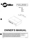
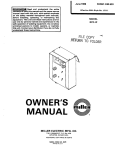
Miller®
MODEL
MR-5/PULSTAR 450®
COMPUTER INTERFACE
GAS/CURRENT SENSING
CONTROL
OWNER’S MANUAL
IMPORTANT: Read and understand the entire contents of both this
manual and the power source manual used with this unit, with special
emphasis on the safety material throughout both manuals, before installing, operating, or maintaining this equipment. This unit and these
instructions are for use only by persons trained and experienced in the
safe operation of welding equipment. Do not allow untrained persons to
install, operate, or maintain this unit. Contact your distributor if you do
not fully understand these instructions.
PRINTED IN U.S.A.
Miller Electric Mfg. Co.
~
~a.Box 1079
Appleton, WI 54912 USA
Tel. 414-734-9821
ADDITIONAL COPY PRICE 95 CENTS
El
I.
L..
LIMITED WARRANTY
EFFECTIVE: FEBRUARY 16, 1988
This warranty supersedes all previous MILLER warranties and is exclusivewith no other guarantees or warranties expressed or implied.
LIMITED WARRANTY — Subject to the terms and conditions
In the case of Millers breachof warranty or any other duty with
hereof, Miller Electric Mfg. Co., Appleton. Wisconsin warrants respect to the quality of any goods, the exclusive remedies
to its Distributor/Dealerthat all new and unused Equipmentfur- therefore shall be, at Miller’s option (1) repairor (2) replacement
nished by Miller is free from defectin workmanship andmaterial or, where authorized in writing by Miller in appropriate cases,
as of the time and place of delivety by Miller. No warranty is (3) the reasonable cost of repair or replacement at an authormade by Miller with respect to engines, trade accessories or ized Miller service station or (4) payment of orcredit for the purother items manufactured by others. Such engines, trade ac- chase price (less reasonable depreciation based upon actual
cessories and other items are sold subject to the warranties of
their respective manufacturers, if any. All engines are warranted by their manufacturer for one year from date of original
purchase, except Tecumseh engines which have a two year
warranty.
use) upon return ofthe goods at Customers risk and expense.
MILLER’s option of repair or replacement will be P.O. B., Factory at Appleton, Wisconsin, or FOB, at a MILLER authorized
service facility, therefore, no compensation for transportation
costs of any kind will be allowed. Upon receipt of notice of apparent defect or failure, Miller shall instruct the claimant on the
Except as specified below, Miller’s warrantydoes not apply to warranty claim procedures to be followed.
components having normal useful life of less than one (1) year,
such as spot welder tips, relay and contactor points, MILLERMATIC parts that come in contact with the welding wire includ- ANY EXPRESS WARRANTY NOT PROVIDED HEREIN
ing nozzles and nozzle insulators where failure does not result AND ANY IMPLIED WARRANTY, GUARANTY OR REPREfrom defect in workmanship or material.
SENTATION AS TO PERFORMANCE, AND ANY REMEDY
Miller shall be required to honorwarrantyclaims on warranted FOR BREACH OF CONTRACT WHICH, BUT FOR THIS
Equipment in the event of failure resulting from a defect within PROVISION, MIGHTARISE BY IMPLICATION. OPERATION
the following periods from the date of delivery of Equipment to OF LAW, CUSTOM OF TRADE OR COURSE OF DEALING,
INCLUDING ANY IMPLIED WARRANTY OF MERCHANthe original user:
TABILITY OR OF FITNESS FOR PARTICULAR PURPOSE,
1. Arc welders, power sources, robots, and
1 year WITH RESPECT TO ANY AND ALL EQUIPMENT FURNISHED BY MILLER IS EXCLUDED AND DISCLAIMED BY
components
2. Load banks
3. Original main power rectifiers
(labor — 1 year only)
4. All welding guns, feeder/guns and torches
..
. -
5. All other Millermatic Feeders
6. Replacement or repair parts, exclusive of labor
7. Batteries
1 year
3 years
MILLER.
90 days
EXCEPT AS EXPRESSLY PROVIDED BY MILLER IN
WRITING, MILLER PRODUCTS ARE INTENDED FOR ULTIMATE PURCHASE BY COMMERCIAL/INDUSTRIAL USERS
1 year
60 days
6 months
provided that Miller is notified in writing within thirty (30) days of
the date of such failure.
AND FOR OPERATION BY PERSONSTRAINEDAND EXPERIENCED IN THE USE AND MAINTENANCE OF WELDING
EQUIPMENT AND NOT FOR CONSUMERS OR CONSUMER USE. MILLER’S WARRANTIES DO NOT EXTEND
As a matter of general policy only, Miller may honor claims TO, AND NO RESELLER IS AUTHORIZED TO EXTEND
submitted by the original user within the foregoing periods.
MILLER’S WARRANTIES 1O, ANY CONSUMER.
xw’
F.
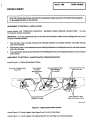
ERRATA SHEET
AMENDMENT TO SECTION 2—INSTALLATION
Amend Section 2-3C. COMPUTER INTERFACE
AC/Contactor Control Connection
-
WELDING POWER SOURCE CONNECTIONS: 115 Volts
IMPORTANT: Cords are supplied that may not be used in this installation. Match cord to welding power source and
computer interfaceavailable.
1. Align keyways, insert 4-socket Amp plug into matching receptacle on computer interface, and rotate threaded
collar fully clockwise.
2. Align keyway, insert 14-pin Amphenol plug into matching receptacle on welding power source, and rotate threaded
collar fully clockwise.
3. Place appropriate remote control switch(es) on the welding power source in the proper position for use of a remote
control device.
AMENDMENT TO SECTION 5— MAINTENANCE & TROUBLESHOOTING
Amend Figure 5-1. Display Board Meter Checks
Rear View of Display circuit
Board PC4
Power Supply
For Wire
Speed 1PM Meter
Input command For Wire
Speed 1PM Meter
.8V = 800 1PM
Ammeter—.1 V—i OOA
Input command For Volts
Meter—.5V = 50V
Power Supply For Volts
Meter And Ammeter 0-SVdc
Rd. 0-111 565
FIgure 5-1. DIsplay Board Meter Checks
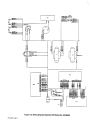
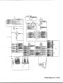
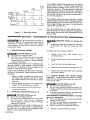
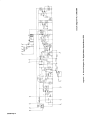
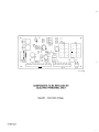
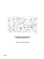
Amend Figure 5-5. Wiring Diagram (see Pages 2 and 3 on this Errata Sheet)
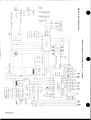
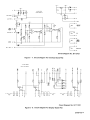
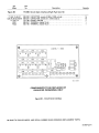
Amend Figure 5-7. Circuit Diagram For Interface Board P03. (see Page 4 on this Errata Sheet)
Figure 5-5. WIrIng Diagram Effective With SerIal No. JK636569
OM-883A Page 2
Wiring Diagram No. D-129 908
.15 V.
‘24
AD
•24
V.
V.
0
G
A
WELD START
.~
CFWD)
06
AB
BE
B
Ci
CR5
C43T~
WELD
AL
CURRENT
RELAC-
JOG IREV)
CDB44GJ
CCC
AK
REV. RELAY
CR6
GAS
CR2
CURRENT
T~,DETECT
6
CR4
C~IITAC~
CIrcuIt DIagram No. 6-128 018-A
FIgure 5-7. CircuIt DIagram For Interface Board PC3 Effective
With SerIal Number JK585798 Thru KABI 9026
.1EV.
BC
•24V.
C
.2’v.
6
C-
0I
l.ELD START
AE
CR
.CCG (P~CI ~
£~
MILD
AL
2PBENT
RELAY
..~
H
T~.L.
A.J
IBEVI P4
CR6
GAS
r—~wCr
~CR2
CLBKENT
DETECT
BEV. BELAY
K
CR4
L~AC
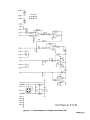
Circuit DIagram No. 6-137 905
FIgure 5-7. CircuIt DIagram For Interface Board PC3 Effective With Serial No. KA81 9027
OM-883A Page 4
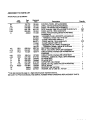
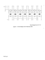
AMENDMENT TO PARTS LIST
Amend Parts Ust as follows:
Mkgs.
Dia.
2-1
2-4
2-27
2-30
2-40
2-
Part
No.
116 774
070 634
049 989
604 109
090 890
Added
Replaced
With
129 949
123 154
118 676
604 109
135 304
110 438
048 284
079 534
079 531
604 571
116964
111 122
4-5
4-12
4-21
SRi
CR1
P03
035 914
034 841
113 221
109770
035 704
109 006
128 014
4-21
4-23
999912-3
1212-
PC3
R05
C3
C4
CS
D16
REED
128 014
073 730
072 130
005 023
073 739
028351
079687
Added
Added
137905
073 730
Deleted
Deleted
073 739
028351
136595
136584
007 501
Descnption
CONTROL PANEL, (Effw/JK636569)
LABEL, warning general precuationary
CABLE, volt-sensing (Eff wIJH296872)
WIRE, stranded l6ga (Elf w/JH296872) (order by ft)
CABLE, port No. 18 8/c (order by ft)
CABLE, interconnecting 25ff (Eff w/JK678982)
(consisting of)
HOUSING PLUG & SOCKETS, (consisting of)
TERMINAL, female lskt 14-18 wire
CLAMP, cable strain relief sz 11
CABLE, port No. 18 4/c (order by if)
•CLAMP,cable97-3057-1012
HOUSING PLUG & PINS, (consisting of)
•TERMINAL,temalelplnsz45l6-22w1r0
RECTIFIER, integ 30A 600V
RELAY, end 24VAC DPDT (Eff w/JK636569)
CIRCUITCARD, interface (Elf w/JK585798 thru
KA849026)
CIRCUITCARD, Interface (EffwIKA8
7)
TERMINAL, (added dia. mkgs.) (Eff w/JK636569)
Eff w/KA81 9027
Eff w/KA819027
CAPACITOR, (qty change)
DIODE,(qtychg,addedDl6)(Effw/JK585798)
RELAY, current
BRACKET mtg reed relay
WASHER, flat nyl .265 ID x .43700
Quantity
..
6ft
1
1
4
1
25ff
I
I
14
1
1
...
~Firstdigit represents page no digits following dash represent item no.
BE SURE To PROVIDE MODEL AND SERIAL NUMBER WHEN ORDERING REPLACEMENT PARTS.
-
I
1
26ff
1
I
1
1
4
I
I
2
TABLE OF CONTENTS
Section No.
SECTION 1
1
1
1
-
1.
2.
3.
SECTION 2
2-1.
2 2.
2 3.
2 4.
2 5.
-
-
-
-
Page No.
INTRODUCTION
General Information And Safety
Receiving-Handling
Description
-
2
2
2
INSTALLATION
Location
Gas/Current Sensing Control Connections
Computer Interface Welding Power Source Connections
Computer Interface Welding Power Source Interface Connections.
Computer Interface Terminal Strip Connections
-
2
3
3
4
5
SECTION 3 FUNCTION OF CONTROLS
-
3-1.
3 2.
3 3.
3 4.
3 5.
3 6.
3 7.
-
-
PowerSwitch
Peak Amperage Control
Overload Protection
Voltmeter
Wire Speed Meter
Ammeter
Indicator Lights
6
6
6
7
7
7
7
SECTION 4 SEQUENCE OF OPERATION
-
4
4
4
-
1.
2.
3.
SECTION 5
5
5
5
5
5
5
-
1.
2.
3.
4.
5.
6.
Input Signal From Welding Power Source
Output Signals From Computer Interface
Wire Stick Check
-
7
7
7
MAINTENANCE & TROUBLESHOOTING
Inspection And Upkeep
Overload Protection
Display Board PC4 Meter Check
Board Replacement Procedures
Troubleshooting Chart
Use Of Indicator Lights For Troubleshooting
8
8
8
10
10
13
SECTION 1
-
INTRODUCTION
Model
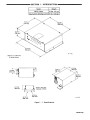
Weight
MR-5 Pulstar
31 lbs. (14 kg)
Gas/Current Sensing Control 5 lbs. (2.3 kg)
+Add 2-1/2 in. (63.5 mm)
for brake resistor
3-1/2 in.
(89 mm)
4-1/2 in.
(108 mm)
~7~,5I16
.~.==—--—~-—-=4~j
9-7/8
10-1/2 in.
(267 mm)
in. (7.9 mm)
Diameter 2 Holes
in.
TB-I 10320
(251 mm)
Figure 1
-
1. Specifications
OM-883 Page 1
1
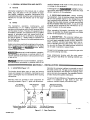
1. GENERAL INFORMATION AND SAFETY
-
A.
carefully followed could result in minor personal injury
or damage to this equipment.
General
A third signal word, I~~jJ,
highlights instructions which need special emphasis to obtain the most
efficient operation of this equipment.
Information presented in this manual and on various
labels, tags, and plates on the unit pertains to equipment design, installation, operation, maintenance, and
troubleshooting which should be read, understood, and
1 2. RECEIVING-HANDLING Before installing
this equipment, clean all packing material from around
the unit and carefully inspect for any damage that may
have occurred during shipment. Any claim for loss or
damage that may have occurred in transit must be filed
by the purchaser with the carrier. A copy of the bill
-
followed for the safe and effective use of this equipment.
B.
Safety
The installation,
operation,
maintenance,
-
of lading will be furnished by the manufacturer on request if occasion to file claim arises.
and
troubleshooting of arc welding equipment requires
practices and procedures which ensure personal safety
and the safety of others. Therefore, this equipment is to
be installed, operated, and maintained only by qualified
persons in accordance with this manual and all ap-
When requesting information concerning this equipment, it is essential that Model Description and Serial
Number of the equipment be supplied.
plicable codes such as, but not limited to, those listed at
the end of Section 1 Safety Rules For Operation Of
1 3. DESCRIPTION The computer interface control contains wire feed speed, weld background voltage,
and weld peak amperage control circuitry, digital am-
-
Arc Welding Power Source in the welding power source
Owner’s Manual.
-
meter, voltmeter, and wire feed speed meter, and circuitry to interface with the robot control. The control is
for use with the Pulstar 450 welding power source and
can be used in standard or pulsed mode.
Safety instructions specifically pertaining to this unit appear throughout this manual highlighted by the signal
words WARNING and CAUTION which identify
different levels of hazard.
The gas/current sensing control contains the gas valve
and current sensing reed relay.
statements include installation, operation,
and maintenance procedures or practices which if not
carefully followed could result in serious personal injury
or loss of life.
These components function with the robot system
when using the Gas Metal Arc Welding (GMAW) process.
CAUTION statements include installation, operation,
and maintenance procedures or practices which if not
SECTION 2
2
-
-
INSTALLATION
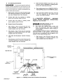
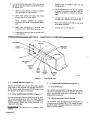
1. LOCATION (Figure 1-1)
The location should allow room to open and remove
covers and wrappers for installation, maintenance, and
repair. Lead lengths must be considered when locating
components.
Mounting holes are provided in each component for
mounting purposes. Figure 1 -1 gives unit dimensions.
Arc Sensing
Receptacle RC12
Normally the computer interface is mounted on top of
the robot control unit. The gas/current sensing control
should be mounted in line between the welding power
source and wire drive assembly. See installation section
of robot manual for specific information.
The service life and efficiency of the system are reduced
when it is subjected to high levels of dust, dirt,
moisture, corrosive vapors, and extreme heat.
Peak Amperage
Strain
Gas/Current Sensing
Control
Relief
Control Receptacle RC9
welding Power Source
Interface Receptacle
RC17
TB-116 632
Figure 2-1. Rear Panel View
OM-883 Page 2
D.
2 2. GAS/CURRENT SENSING CONTROL CONNECTIONS (Figures 2-1 And 2-2)
-
WARNING: ELECTRIC SHOCK can kill.
•
•
Do not touch live electrical parts.
Shut down unit, welding power source, and
robot~. and disconnect input power employing
“lockout/tagging procedures” before making interconnections.
Lockout/tagging procedures consist of padlocking line
disconnect switch in open position, removing fuses
from fuse box, or shutting off and red-tagging circuit
breaker or other disconnecting device.
A.
Computer Interface Gas/Current Sensing
Control Connections
-
Connect hose from gas regulator/flowmeter (customer
supplied) at gas source to IN fitting on gas/current sensing control. Connect gas hose from wire drive
assembly to fitting on gas/current sensing control. The
gas flow must be accurately controlled by a
regulator/flowmeter at the source.
E. Touch Sensor Connections
Connect cord with two friction connectors coming from
gas/current sensing control to touch sensor leads coming from outlet cable. Polarity is not important for this
connection.
2
1. Align keyways, insert 14-pin Amp plug into mat-
ching receptacle on computer interface, and
rotate threaded collar fully clockwise.
Gas Connections
-
3. COMPUTER
INTERFACE
-
WELDING
POWER SOURCE CONNECTIONS (Figures 2-1 And
2-2)
WARNING: ELECTRIC SHOCK can kill.
2. Align keyways, insert 16-pin Amp plug into matching receptacle on gas/current sensing control,
and rotate threaded collar fully clockwise.
B. Gas/Current Sensing Control
nections
-
Motor Con-
Align keyways, insert 14-pin plug from motor into matching receptacle on gas/current sensing control, and
rotate threaded collar fully clockwise.
C.
Weld Cable Connections
Route cable from welding power source positive weld
output terminal, through the gas/current sensing control, to the wire drive assembly and connect cable to
weld cable terminal (see Motor/Drive Assembly
Owner’s Manual for location).
•
•
Do not touch live electrical parts.
Shut down unit, welding power source, and
robot, and disconnect input power employing
“lockout/tagging procedures” before making interconnections.
Lockout/tagging procedures consist of padlocking line
disconnect switch in open position, removing fuses
from fuse box, or shutting off and red-tagging circuit
breaker or other disconnecting device.
There are several cords used for interconnections between the computer interface and welding power
source. Examine and select the proper cord for the
following connections.
115 Volts AC/Contactor
Sensor
Connections
Figure 2
-
2. Interconnection Diagram
OM-883 Page 3
A.
2. Insert two-pole twistlock plug from cord into
contactor control receptacle on welding power
source, and rotate plug clockwise.
Arc Sensing Connections
EI~~k~IE
Ifdc electrode negative welding is
desired, reverse connections so the lead with a ring
terminal is connected to the negative weld output terminal, and the lead with a clamp is connected to the
positive weld output terminal.
3. Place welding power source REMOTE CONTACTOR CONTROL switch in the REMOTE position.
1. Align keyway, insert four-socket Amphenol plug
into matching receptacle on computer interface,
4. Insert three-pole twistlock plug from cord into
115 VAC receptacle on the welding power
source, and rotate clockwise.
and rotate threaded collar fully clockwise.
2.
Connect lead with ring terminal to welding
power source positive output terminal.
2 4. COMPUTER INTERFACE
WELDING
POWER SOURCE INTERFACE CONNECTIONS
(Figures 2-1, 2-2, And 2-3)
-
3. Connect lead with clamp to welding power
-
source negative output terminal.
B.
WARNING: ELECTRIC SHOCK can kill.
•
Do not touch live electrical parts.
•
Shut down unit, welding power source, and
robot, and disconnect input power employing
“lockout/tagging procedures” before making interconnections.
Output Control Connections
1. Align keyway, insert 10-socket plug into matching receptacle on computer interface, and
rotate threaded collar fully clockwise.
Lockout/tagging procedures consist of padlocking line
2. Align keyway, insert 10-pin plug into matching
receptacle on welding power source, and rotate
threaded collar fully clockwise.
C.
disconnect switch in open position, removing fuses
from fuse box, or shutting off and red-tagging circuit
breaker or other disconnecting device.
115 Volts AC/Contactor Control Connections
1.
Align keyway, insert 24-socket plug into matching receptacle on computer interface, and
rotate threaded collar fully clockwise.
1. Align keyways, insert four-socket Amp plug into
matching receptacle on computer interface, and
rotate threaded collar fully clockwise.
welding Power Source
Computer
Interface
Right Side View
Interface
Robot
Control Unit
I,
I
Green Lead
/
Figure 2
OM-883 Page 4
-
Blue Lead
Welding
Current
Wire Stick 4+)
(WCRI Detect
3. Welding Power Source Interface Connections
TC-1 14937
2. Align keyways, insert four-, six-, and ten-pin
plugs from interconnecting cord into matching
receptacles on bottom of welding power source
interface, and rotate threaded collars fully
clockwise.
Lockout/tagging procedures consist of padlocking line
disconnect switch in open position, removing fuses
from fuse box, or shutting off and red-tagging circuit
breaker or other disconnecting device.
There are several terminal strips inside the computer interface for control connections. Remove unit top cover,
loosen screws on strain relief on unit rear panel if
necessary, and locate appropriate terminal strip for connection. Tighten screws on strain relief if necessary,
and reinstall top cover when procedure is finished.
3. Remove welding power source interface side
panel.
4. Route remaining cord from computer interface
through strain relief in bottom of welding power
source interface, to 14-position terminal strip.
The ARC FAILURE light on the computer interface front
panel is turned on and off by a signal from the robot
controt unit. Locate supplied length of 18 gauge/2 conductor cord for this connection, and proceed as follows:
5. Connect leads as follows:
a. Red lead to terminal 52.
1. For robot control units with no other connections at function control terminal strip 2 (Figure
2-4):
b. Blue lead to terminal 50.
c.
White lead to terminal 35.
a. Open robot control unit door, and locate
function control terminal strip 2.
d. Green lead to terminal 36.
e. Long green lead with ring terminal connects
b. Route cord under cross member below door.
to chassis ground.
c. Make cord connections to terminal strip
common and the Weld Alarm terminal.
6. Reinstall and secure side panel.
5. COMPUTER INTERFACE TERMINAL STRIP
CONNECTIONS
2
-
WARNING: ELECTRIC SHOCK can kill.
d. Close robot control unit door, and route cord
through strain relief on rear panel of computer interface.
•
•
e. Connect cord to 2TE and 2TF.
Do not touch live electrical parts.
Shut down unit, welding power source, and robot
and disconnect input power employing
“lockout! tagging procedures” before making interconnections.
Function Control Terminal
Strip 2 Common Terminal
2TE
0
Robot
Control Unit
+24VDC
Computer
Interface
2TF
Weld Alarm
Terminal
Arc Failure
Indicator Light
To Voltage Source
(115VAC, 24VAC, 24VDC)
Function Control Terminal
Strip 2 Common Terminal
Robot
Control Unit
I
-
—--O
2TE
.24VD0
Isolation Relay
Arc Failure
Indicator Light
Jig
Interface
Weld Alarm
Terminal
Figure 2
-
4. Arc Failure Light Connections
L
TA-i 15648-A
OM-883 Page 5
2. For robot control units when 115 or 24 vac, or
24 vdc, is used at function control terminal strip
2T (Figure 2-4):
f.
Connect cord to isolation relay coil and
voltage source.
g. Cut off terminals from one end of supplied
18 gauge/2-conductor cord, and install terminals to connect to contacts on isolation
a. Obtain a 115 or 24 vac, or 24 vdc, isolation
relay and install into jig interface.
relay.
b. Open robot control unit door, and locate
function control terminal strip 2.
c.
d.
e.
Route
customer
supplied 18
h. Connect one end of cord to a set of
normally-open contacts on isolation relay.
gauge/2-
conductor cord under cross member below
door.
i.
Make cord connections to terminal strip
common and the Weld Alarm terminal.
Close robot control unit door, and route cord
j.
Route cord through strain relief on rear panel
of computer interface.
Connect cord to 2TE and 2TF.
to jig interface.
SECTION 3
-
FUNCTION OF CONTP~’
Power Switch.
Indicator
Light
Figure 3
3
-
-
-
1. POWER SWITCH (Figure 3-1)
2. PEAK AMPERAGE CONTROL (Figure 2-1)
The Peak Amperage control provides a means of selecting a peak amperage level when the Mode Selector
switch on the welding power source is in the 6OPPS or
12OPPS position. Rotate the control clockwise to increase peak amperage.
jj~~Jj
welding.
OM-883 Page 6
TB-114
436
1. Front Panel View
Placing the POWER switch in the ON position applies
input power to the interface. The interface must be on
for the robot to weld. Placing the POWER switch in the
OFF position shuts down the interface.
3
Failure
Indicator
Light
This control may be ad/usted while
3
-
3. OVERLOAD PROTECTION (Figure 3-1)
A.
Fuse Protection
The interface is protected from damage due to an internal short or excessive overload by fuse Fl. If fuse Fl
opens, the interface shuts down. See Section 5-2 for
replacement procedures.
B.
Wire Drive Motor Circuit Breaker
The wire drive motor is protected from damage due to
overload by circuit breaker CB1. If CB1 opens, the interface shuts down. Manually depress the reset button to
reset the circuit breaker.
3
The GAS light turns on when the gas valve is energized
to indicate shielding gas flow.
4. VOLTMETER (Figure 3-1)
-
The voltmeter displays weld voltage to the nearest tenth
of a volt while welding and preset voltage while idling.
3
5. WIRE SPEED METER (Figure 3-1)
-
The wire speed meter displays preset wire feed speed to
the nearest inch per minute while welding and idling.
Actual and preset wire feed speed are the same due to
the wire feed speed feedback circuit.
The CONTACTOR light turns on when the welding
power source contactor is energized to indicate that
weld output is available.
The WIRE FEED light turns on when the wire drive
motor is energized to indicate that wire is feeding.
The CURRENT light turns on when the current detect
relay is energized to indicate that an arc is established.
3 -6. AMMETER (Figure 3-1)
The ammeter displays weld peak amperage to the
nearest amp while welding and preset amperage while
idling.
3
The ARC FAILURE light turns on when there is an arc
outage while welding.
7. INDICATOR LIGHTS (Figure 3-1)
-
There are five indicator lights on the interface. These
are visual indications of various process functions.
SECTION 4
-
SEQUENCE OF OPERATION
4 1. INPUT SIGNAL FROM WELDING POWER
SOURCE (Figure 4-1) The welding power source
and wire drive motor send signals to the computer interface. These signals are used to determine weld
parameters. During welding these signals are compared
to preset welding values and compensations are made
to keep weld parameters at preset levels.
Arc Initiation
-
-
Wire Start Relay
Open
Close
Arc Initiation
Close
~
Welding Current
No-Load
Welding
Voltage
o to 50V
H
Open
I
Crater
________
I
Output To Motor
—IInput
From Motor
Weld Abnormal
~
—
Open when abnormality occurs.
Time
Start
Start
Time
TA-I 14379
TA-i 14379
Figure 4
Figure 4
-
-
2. Output Signal Timing Chart
I. Input Signal Timing Chart
3. WIRE STICK CHECK (Figure 4-3) After the
weld is completed, the wire stick check is performed to
determine if the welding wire has burned back out of
the weld puddle.
4
4 2. OUTPUT SIGNALS FROM COMPUTER INTERFACE (Figure 4-2) The interface interprets the
input signals from the welding power source, wire drive
motor, robot, and wire stick check circuit. The output
of the computer interface regulates the welding power
source and wire feed functions while welding.
-
-
-
-
Feedback is used to determine if the wire is free of the
weld. If the feedback indicates the wire is free of the
weld, the robot can cycle to its next sequence.
OM-583 Page 7
1OVDC
If the feedback indicates the wire is stuck, the welding
power source is sent a 1 .25 VDC command signal to
provide minimum welding power source output. The
contactor is pulsed on. If the wire was stuck, the pulsed
voltage should be enough to free the wire. Feedback is
used to determine if the wire is now free of the weld. If
the feedback indicates the wire is free, the robot can cycle to its next sequence.
5VDC
2.5VDC
Voltage 1.25VDC
Command
Wire Stick
Check
If the feedback indicates the wire is still stuck, a higher
200 miIIiseconds.—~..]
I
Contactor
I
I
I
I
voltage command is given, and the contactor pulsed to
free the welding wire. The check is performed and two
more voltage increases are used to try and free the
379
If the wire remains stuck, the robot will shut down, a
TA-114
Figure 4
-
3. Wire
Stick Check
SECTION 5
-
welding wire (see Figure 4-3).
Weld Abnormal error will be displayed on the robot program module, and the wire must be physically removed
from the weld.
MAINTENANCE & TROUBLESHOOTING
IMPORTANT: Every six months inspect the labels on
this unit for legibility. All precautionary labels must be
maintained in a clearly readable state and replaced
when necessary. See the Parts List for part number of
precautionary labels.
~ULLi~EIMPROPER
5
To replace the fuse, proceed as follows:
-
1. INSPECTION AND UPKEEP
FUSES can damage this
unit.
•
If replacement becomes necessary, use only fuses
of the proper size, type, and rating (see Parts
List).
ELECTRIC SHOCK can kill.
Do not touch live electrical parts.
Shut down unit, welding power source, and robot
and disconnect input power employing
“lockout! tagging procedures” before internally
inspecting or servicing.
WARNING:
•
•
1. Depress and rotate fuse
counterclockwise.
2.
and cables; give particular attention to frayed
and cracked insulation and areas where it enters
equipment.
2. Remove grease and grime from components,
moisture from electrical parts and cables.
I Inspect motor control relay CR2 and clean or
replace as necessary.
5
-
2. OVERLOAD PROTECTION (Figure 3-1)
WARNING: ELECTRIC SHOCK can kill.
•
•
Do not touch live electricalparts.
Shut down unit, welding power source, and robot
and disconnect input power employing
“lockout/tagging procedures” before internally
inspecting or servicing.
Lockout/tagging procedures consist of padlocking line
disconnect switch in open position, removing fuses
from fuse box, or shutting off and red-tagging circuit
breaker or other disconnecting device.
OM-883 Page 8
Pull out fuse with cover when fuse holder cover
is free.
Lockout/tagging procedures consist of padlocking line
disconnect switch in open position, removing fuses
from fuse box, or shutting off and red-tagging circuit
breaker or other disconnecting device.
Usage and shop conditions will determine the frequency
and type of maintenance. Inspect equipment monthly
as follows:
1. Repair or replace, as required, all hoses, cords,
holder cover
3. Insert new fuse into fuse holder cover.
4. Install fuse with fuse holder cover back into unit.
5. Depress and rotate fuse holder cover clockwise
until cover is secure.
5 - 3. DISPLAY BOARD PC4 METER CHECK
(Figure 5-1) - Check points are provided on the display
board PC4 for checking power supply and input com-
mand for the meters.
WARNING: ELECTRIC SHOCK can kill.
•
•
Do not touch live electricalparts.
Be sure that personnel performing testing procedures are familiar with and follow standard safety practices.
•
Shut down unit before making or changing meter
or test equipment lead connections.
ELECTROSTATIC DISCHARGE (ESD) can damage
electronic components.
•
Put on a properly grounded wrist strap BEFORE
handling circuit boards.
•
Transport all static-sensitive components in proper static-shielding carriers and packages.
•
Perform work only at a static-safe work area.
1. Remove computer interface top cover.
vini
Power Supply For~—V
Wire Speed 1PM
Meter 0 - 5 Vdc
K
Power Supply For
- 5Vdc
Voltmeter 0
1+
Input Command For
0 - .5 Vdc~
Vin2
Input Command For
Wire Speed 1PM
Meter 0 - .8 Vdc’
v2 +
*Corresponds to 0 - 50 volt welding
power source output.
**Corresponds to 0 - 800 ipm output
of the wire drive motor.
Figure 5
Figure 5
1. Display Board Meter Checks
-
2. Circuit Board Replacement
OM-583 Page 9
b.
Gently pull meter straight out of socket. Re-
2. Locate display board PC4.
tain spacers.
3.
Check voltage according to Figure 5-1.
4.
If a meter power supply and command voltage is
correct and the meter is not working, replace the
meter (see Section 5-4).
5.
5-41.
REPLACEMENT
d.
Push meter into socket with meter supports
e. Reinstall lock washers and nuts to secure
meter to board. Do not overtighten nuts or
meter may be damaged.
rect, replace display board PC4 (see Section
-
Slide spacers onto new meter support.
protruding through to rear of PC4.
If the power supply or command voltage is incor-
5 4. BOARD
(Figure 5-2)
c.
6. To install replacement display board, carefully
line board up with front panel openings for
meters and LED’s.
PROCEDURES
~
ELECTRIC SHOCK can kill.
Do not touch live electrical parts.
Shut down unit, welding power source, and
robot, and disconnect input power employing
“lockout!tagging procedures” before inspecting
or servicing.
Lockout/tagging procedures consist of padlocking line
disconnect switch in the open position, removing fuses
from fuse box, or shutting off and red-tagging circuit
breaker or other disconnecting device.
ELECTROSTATIC DISCHARGE (ESD) can damage
circuit board components.
•
Put on properly grounded wrist strap BEFORE
handling circuit boards.
•
Transport all static-sensitive components in proper static-shielding carriers or packages.
•
Perform work only at a static-safe work area.
INCORRECTLY INSTALLED PLUGS can damage
circuit boards.
•
Be sure that plugs are properly aligned and installed onto connectors before resuming operation.
EXCESSIVE PRESSURE can break circuit board.
•
Use only minimal pressure and gentle movement
when disconnecting or connecting board plugs or
boards.
7. Reinstall securing screws.
•
•
8. Reconnect PLG2O and PLG24 to matching
receptacles on new PC4.
9. Reinstall unit top cover.
B. Motor Board PC2 Replacement
1. Remove unit top cover.
2.
Remove securing screw and unlatch standoff.
3.
Gently pull board from receptacle RCS.
4.
Insert new board into RC5.
5.
Reinstall securing screw and latch standoff.
6.
Reinstall unit top cover.
C.
Replacement
Boards
Procedure
For
Remaining
1. Remove unit top cover and locate board.
WI~I~IE
All directions, such as left or right, are
with respect to the operator facing the unit front panel.
Retain all hardware removed during this procedure for
reinstaliation.
A.
2.
Disconnect plug(s) from board.
3.
Unlatch standoffs and slide board out of retaining rail.
4.
Slide new board into retaining rail and latch standoffs.
Display Board PC4 And Meter Replacement
1. Remove unit top cover.
5. Connect plug(s) to matching receptacle(s) on
new board.
2. Remove screws securing board to stand-offs. Do
not remove stand-otis.
3.
ching receptacles on PC4.
4.
6. Reinstall unit top cover.
Disconnect plugs PLG2O and PLG24 from matGently pull board straight away from front panel.
Do not pull up or down; otherwise, the meters
and LED’s may be damaged.
5. To replace meter(s) proceed as follows:
a. Remove nuts and lock washers from meter
support.
OM-883 Page 10
5
-
5. TROUBLESHOOTING CHART
WARNING: ELECTRIC SHOCK can kill.
•
•
Do not touch live electrical parts.
Shut down unit, welding power source, and robot
and disconnect input power employing
“lockout! tagging procedures” before internally
inspecting or servicing.
Lockout/tagging procedures consist of padlocking line
disconnect switch in open position, removing fuses
from fuse box, or shutting off and red-tagging circuit
breaker or other disconnecting device.
MOVING PARTS can cause serious injury.
•
Keep clear of moving parts.
HOT SURFACES can cause severe burns.
•
Allow coollng period before servicing.
Troubleshooting to be performed only by qualified persons.
It is assumed that the computer interface was properly
installed according to Section 2 of this manual, the
TROUBLE
Unit does not operate.
No meter display.
No wire feed.
Wire feeds at maximum only.
operator is familiar with the function of controls, the
unit was working properly, and that the trouble is not
related to the welding process. The following chart is
designed to diagnose and provide remedies for some of
the troubles that may develop in this unit.
Use this chart in conjunction with the circuit diagrams
while performing troubleshooting procedures. If the
trouble is not remedied after performing these procedures, the nearest Factory Authorized Service Station should be contacted. In all cases of equipment
malfunction, the manufacturer’s recommendations
should be strictly followed.
PROBABLE CAUSE
REMEDY
Fuse Fl open.
Check Fl, and replace if necessary (see Section
5-2). Correct overload problem before continuing
operation.
Circuit breaker CB1 tripped.
Check CB1, and reset if necessary. Correct
overload problem before continuing operation.
Meter not working.
Use check points on display board PC4 to deter
mine if power is available to meter (see Section
5-3). If check points are okay, replace meter (see
Section 5-4).
Display board
working.
Use check points to determine if power is available
(see Section 5-3). If check points do not test
okay, replace PC4 (see Section 5-4).
PC4 not
Robot signal.
Check input signal from robot to motor board
PC2. Signal should be 0-10 vdc between pins K
and B (common) on RC5.
Relay CR1 not working.
Replace CR1.
Motor board PC2 not work-
Replace PC2 (see Section 5A).
ing.
Tach board PC5 at wire
drive motor not working.
Replace PC5.
OM-883 Page 11
TROUBLE
No arc voltage control.
Robot shuts down due to
Touch Sensor error.
Robot moves when welding
wire is stuck.
Wire speed (1PM) meter
goes to zero.
No wire retract.
Robot shuts down.
OM-883 Page 12
PROBABLE CAUSE
OutpUt
tions.
control
connec-
REMEDY
Check and secure connections (see Section 2-3).
Arc sensing connections.
Check and secure connections (see Section 2-3).
Voltage board
working.
Replace PCi (see Section 5-4).
PCi
not
Incorrect robot command
voltage.
Check robot command voltage at voltage board
PCi. Command voltage should be 0-10 vdc bet
ween pins K and A (common) at RC14.
Touch Sensor connections.
Check continuity of leads between gun/torch and
gas/current sensing control. Repair or replace.
Secure all connections.
Control relay CR3 not working.
Replace CR3.
Wire stick connection.
Be sure that red lead is connected to terminal 52
and blue lead is connected to terminal 50 on
welding power source interface 14 position ter
minal strip.
Arc sensing connections.
Check and secure connections (see Section 2-3).
Incorrect robot command
voltage.
Check robot command voltage at motor board
PC2. Signal should be 0-10 vdc between pins K
and B (common) at RC5.
Motor board PC2 not working.
Replace PC2 (see Section 5-4).
Control relay CR2 not working.
Replace CR2.
Interface board PC3 not
working.
Replace PC3 (see Section 5-4).
Incorrect robot command
voltage.
Check robot command voltage at motor board
PC2. Signal should be 0-10 vdc between pins K
and B (common) at RC5.
Loose weld output connections.
Clean and tighten connections.
Interconnecting cords.
Check all interconnecting cords for breaks; repair
or replace. Check and secure all connections.
Interface board PC3 not
working.
Replace PC3 (see Section 5-4).
5
-
6. USE OF INDICATOR LIGHTS FOR TROUBLESHOOTING
On
off
Gas Indicator Light
IT
Gas flows:
Gas flows:
Gas does not flow:
System normal (on).
Check gas valve operation.
Check gas valve operation
Gas does not flow:
System normal (off).
and gas line for leaks.
Check interface board PC3.
On
cmi!
•Contactor Indicator Li~~
‘I,
—
1ff
I
Contactor closed:
Contactor open:
Contactor closed:
Contactor Open:
System normal (on).
Check interconnecting
cords.
Check display board PC4.
System normal (off).
Check interface board PC3.
Wire Feed Indicator LI~IIL
On
F
1~
II
Wire feeds:
Wire does not feed:
Wire feeds:
Wire does not feed:
System normal (on).
Check circuit breaker CB1.
Check input signal from
robot to motor board P02.
Signal should be 0-10 vdc
between pins K and B
(common) at RC5.
Check motor board P02.
System normal (off).
Check relay CR1.
Check interface board PC3.
~Jn
1~’
Off
Current Indicator Light
-~
Arc started:
No arc:
Arc started:
No arc:
System normal (on).
Replace reed relay.
Replace reed relay.
System normal (off).
On
Arc Failure Indicator Light
-‘I”
I,,,
No arc:
Arc started:
No arc:
Arc started:
Check weld parameters.
Check signal from robot.
Signal should be 24 vdc
between terminals 2TE and
2TF.
Normal during idling.
Normal while welding.
Check display board
PC4.
OM-883 Page 13
OM-883 Page 14
BA
A-P ON RCI4
AA-AK ON RCI~
~
AC
RCI6
AF~
P
AA
N
AK
AH
AG
AJ
J
F
C
0
E
-
A
I ~V.
B
Circuit Diagram No. B-116 188
Figure 5
-
4. Circuit Diagram For Voltage Control Board PCi
OM-883 Page 15
Figure 5
OM-883 Page 16
-
5. Wiring Diagram
Wiring Diagram No. D-116 082
OM-883 Page 17
OM-883 Page 18
.15 V.
•24 V.
07
D
‘24 V.
A
D6
WELD START
AE
CR
J~
B
6
(FWD) J
C GAS
H
CR5
WELD
WIREFEED
L
AL
C~ENT
RELAY AJ
AJG (REV) N
GAS
E
CR2
COE4.~4
R~oT
DETECT
AK
AN
AA
REV. RELAY
k
CR4
C~(TACTOR
AC
Circuit Diagram No. B-113 431
Figure 5
7. Circuit Diagram For Interface Board PC3
-
A-P ON RC2O
AA-AF ON RC24
I
5
C)
C
C
S
z
r
m
>
Th
m
C
—
&
0
II
LED~
A A A A A
RC2~
Y~
71 ,17j~
AAAA
~C2I
A A A A A
RC22
,171 Y~
Circuit Diagram No. B-ill 341
Figure 5
-
8. Circuit Diagram For Display Board PC4
OM-883 Page 19
AP
AE
M
RCZZ
AD
AG
/‘.
CC
AF
7~7CI2
AC
A.J
CC
~C.
C C
Cli
C32
‘—9 F-’
C28
—i H—
—i H—
‘—9 H—
C
I -~
C31
5C21
P
AL
CA
C30
C32
N
AD
—9
‘CC’
~/
‘CC~
G
H
L
H—
—9
C’
AN
AR
AS
C~(
~I46
H--
H-
ci
CS
CAB
C20
H--
H- H--’
3~
3~FJ 7~
~—9
—)
C28
M
C~(
C22
—9 H-—
H-
AN
C C
7721
C5
C24
C29
AK
HC23
~C
‘CC~
~,/
C
C
Ci
H—
—9
C49
C21
‘
K
C
E
B
Circuit Diagram No. B-ill 117
Figure 5
OM-883 Page 20
-
9. Circuit Diagram For RF Filter Board PC6
A
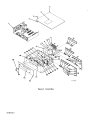
•
PARTS
LIST
T
—
—.
—
5
2.
Figure A
OM-883 Page 1
-
Control Box
Item
No.
Dia.
Mkgs.
Part
No.
Figure A
4
14
15
16
17
18
19
20
21
22
23
24
25
26
R2
P LG9
PLG16
29
30
31
32
33
34
35
36
37
38
39
40
41
42
43
44
116
010
010
070
+ 109
079
030
010
010
030
056
109
047
079
079
096
048
079
010
774
855
853
634
026
683
941
193
199
949
170
041
636
535
739
813
598
534
916
000 527
097 922
115 959
039
073
073
089
716
332
140
647
CONTROL PANEL (Fig B Pg4)
RETAINER, screw No. 2
FASTENER, screw-hd No. 2
LABEL, warning electric shock can kill etc
COVER, top
HEAT SINK
RESISTOR, WW fixed 100 watt5 ohm
TUBING,3/8ODxl8gawallxl/4
TUBING, .275 ID x .048 waIl x 1
HEAT SINK
SHIELD, resistor
CABLE, interconnecting-motor/gas (consisting of)
• HOUSING PLUG & PINS (consisting of)
TERMINAL, male
• .
• CLAMP, cable
CABLE, 18ga15/c(orderbyft)
HOUSING PLUG & SOCKETS {consisting of)
TERMINAL, female
CONNECTOR, clamp 3/4 inch
BLANK, snap-in 7/8 mtg hole
KNOB
CABLE, interconnecting (consisting of)
• PLUG, lOpinMS-3106A-18-IP
CLAMP, cable 97-3057-10-639
CABLE, No.18 10/c (order by ft)
PLUG, lOsocketMS-3106A-18-1S
.
057 360 BLANK, snap-in 3/8 mtg hole
RG1 1
27
28
Quantity
Control Box
2
3
5
6
7
8
9
10
11
12
13
Description
048 283 RECEPTACLE W/PINS (consisting of)
079 535 TERMINAL, male
049 989 CABLE, volt-sensing (consisting of)
PLG12
073 686
039 328
604 109
600 848
600 750
.
.
.
PLUG, 4 socket MS-3106A-14S-2S
CLAMP, cable AN-3057-6
WIRE, stranded 16 ga (order by ft)
WIRE, stranded 12 ga (order by ft)
TERMINAL, ring tongue 1/2 stud
INSULATOR
CLAMP, universal 25 amp
I CN4
601 226
601 228
111 199 CABLE, interconnecting (consisting of)
109 330 PLUG, 24 socket MS-3106A-24-28S
091 100 CLAMP, cable AN-3057-16
604 910 CABLE, 20 ga 5/c (order byft)
604 571 CABLE, l8ga 4/c (order byft)
090 890 CABLE, No. 20 8/c (order by ft)
IC N2
109 159
109 157
IGN3
604 825
109 158
.
.
PLG17
.
.
.
.
.
CONNECTOR
CONNECTOR
.
CABLE, 183/c (order byft)
.
CONNECTOR
1
4
4
1
1
1
1
4
2
1
1
1
1
14
2
1 8ft
1
16
1
1
1
1
1
1
2Oft
1
1
1
4
1
1
1
1 9ft
35ft
1
1
1
1
1
1
6ft
6ft
6ft
1
1
6ft
1
OM-883 Page 2
Item
No.
Dia.
Mkgs.
Part
No.
RC1 2
RC1 7
RC13
C2-4
49
PC4
50
51 PLG2O,21
52
53
54
55
56
57
58
59
60
61
Quantity
Control Box (Cont’d)
Figure A
45
46
47
48
Description
Fl
51
CB1
R4
RC9
Dl
PLG14,15
PLG16
PLG18
PLG19
PLG2O
PLG22
PLG24
113 736
076 624
094 591
089 646
028 291
057 084
117836
073 756
081 380
112 254
089 032
046 432
*012 655
073 487
011 609
011 991
603 856
115 821
047 637
079 534
109 558
090 469
082 798
079 760
079 798
081 379
092 159
084 198
CABINET, control
RECEPTACLE, 4 pin MS-3102A-145-2P
RECEPTACLE, 24 pin MS-3102A-145-2P
RECEPTACLE, 10 pin MS-3102A-18-1P
CAPACITOR, ceramic 0.1 uf 500 volts dc
BUSHING, snap 1/4 ID x 3/8 mtg hole
CIRCUIT CARD, meter (Fig C Pg 11)
STAND-OFF, No. 6-32 x 5/8 x 1/4 hex
HOUSING, terminal header 14 pin
LABEL, Miller robot computer interface
LENS, led 4341
HOLDER, fuse
FUSE, miniature glass 10 amp 250 volts
NUT, speed No. 2
SWITCH, toggle SPDT 15 amp 125 volts
CIRCUIT BREAKER, 1 pole 1 .5 amp 250 volts
POTENTIOMETER, WW 10 turn 2 watt 10K ohm
PLATE, mtg-potentiometer
HOUSING RECEPTACLE & SOCKETS (consisting of)
TERMINAL, female
DIODE, 1 amp 400 volts SP
HOUSING, terminal header 18 pin
HOUSING, terminal header 2 pin
HOUSING, terminal header 12 pin
HOUSING, terminal header 13 pin
HOUSING, terminal header 12 pin
HOUSING, terminal header 16 pin
HOUSING, terminal header 6 pin
*Recommended Spare Parts
+ When ordering a component originally displaying a precautionary label, the label should also be ordered.
BE SURE TO PROVIDE MODEL AND SERIAL NUMBER WHEN ORDERING REPLACEMENT PARTS.
OM-883 Page 3
1
1
1
1
3
1
1
7
2
1
5
1
1
4
1
1
1
1
1
14
2
1
1
1
1
Item
No.
Dia.
Mkgs.
Figure B
1
2
3
4
5
6
7
8
9
10
11
PC2
CR2
Ti
SRi
T2
R3
Ri
Cl
12 CR1
13
iT
14 2T,3T
15
16 PC6
17
18 CR3
19
20 pci
21 PC3
22
23
Part
Description
No.
116 774
Quantity
Control Panel (Fig A Pg 2 Item 1)
071 642 CIRCUIT CARD, digital motor speed (Fig B2 Pg 8)
083 147 GROMMET, screw 8-10 push in
052 964 RELAY, enclosed 24 volts dc DPDT
109 099 TRANSFORMER, control
035 914 RECTIFIER, integrated 30 amp 400 volts
1
1
1
109 017 TRANSFORMER, control
605 741 CLIP, mtg-resistor
079 497 RESISTOR, WW fixed 25 watt 2K ohm
4
030 651 RESISTOR, WW fixed 25 watt 10 ohm
006 426 CLAMP, capacitor 2 inch
031 692 CAPACITOR, electrolyte 750 uf 200 volts dc
034 841 RELAY, 24 volts ac DPDT
038 832 BLOCK, terminal 20 amp 9 pole
038 783 BLOCK, terminal 20 amp 12 pole
121 313 PANEL, mtg-components
110 565 CIRCUIT CARD, filter (Fig B4 Pg 10)
110 391 GUIDE, mtg-circuit card
110 386 RELAY, enclosed 24 volts ac DPDT
110 375 STAND-OFF, support
116 528 CIRCUIT CARD, voltage control (Fig Bi Pg 6)
113 221 CIRCUIT CARD, interface (Fig B3 Pg 9)
009 335 STAND-OFF, No. 4-40 x 5/8 x 1/4
073 730 TERMINAL, header 22 pin
1
1
2
1
1
3
1
7
1
1
2
1
4
Figure B
-
Control Panel
BE SURE TO PROVIDE MODEL AND SERIAL NUMBER WHEN ORDERING REPLACEMENT PARTS.
OM-883 Page 4
+
A2
F7T7
~LiLJ
~fR
~;j
m
RI 7
LJ
EJ
R16
RI5CR2
+
R4
FF1
~IoII
[Jj
03
I
Al
II]
p4
Cu
Cu
Cu
-
o
-
-
U,
—
!C
‘a
U,
0’
Cu
Cu
—
‘a
C)
—
o~
DILJ
D2E]
C2
04
~fj~
CI
-
0’
R6
~RI2
ASSEMBLY
[III]
~
zzz
m
Cu
+Qc9
Ru
UQWUL~I)~
m
~
+
‘C
<<<<<<<<<<
CC
C
CC
CC
RCI4
RCI5
Lii
—
RCI6
+
Ref. C-116 526
COMPONENTS TO BE REPLACED BY
QUALIFIED PERSONNEL ONLY
Figure Bi
OM-883 Page 5
-
Circuit Card, Voltage
Dia.
Part
Mkgs.
No.
Figure Bi
Al
A2
Cl ,2
C3,4
C5-8,11
C9
ClO
CR1
CR2
Dl -4
RI
R2,15,16
R3
R4,14
R5
R6
R7
R8,9
RlO,11
R12,13
R17
R18
RC14
RC15
RC16
VR1
VR2
Description
Quantity
116 528 Circuit Card, Voltage Control (Fig B Pg 4 Item 20)
096275
009 159
039 482
000 348
073 739
000 861
000 340
IC, Iinear324
IC,linear358
CAPACITOR, electrolyte 100 uf 35 volts dc
CAPACITOR, tantalum 0.47 uf 35 volts
CAPACITOR, ceramicO.l uf50voltsdc
CAPACITOR, electrolyte 33 uf 35 volts
CAPACITOR, ceramic 0.01 uf 50 volts
093 558 RELAY, enclosed 120 volts ac 4PDT
1
1
2
2
5
1
1
1
095 033
091 861
079 844
026 202
RELAY, enclosed 24 volts ac 4PDT
SOCKET, relay
SPRING, hoiddown-relay
DIODE, 1 amp 400 volts SP
035 888 RESISTOR, carbon film 0.25 watt 2.2K ohm
1
2
2
4
1
039 331 RESISTOR, carbon film 0.25 watt 4.7K ohm
039 330 RESISTOR, carbon film 0.25 watt 3.9K ohm
000 038 POTENTIOMETER,cermet25turnO.5watt2Kohm
035 887 RESISTOR, carbon film 0.25 watt 3.3K ohm
009 173 POTENTIOMETER, cermet 20 turn 0.5 watt 5K ohm
039 329 RESISTOR, carbonfilmO.25watt2.7Kohm
035 827 RESISTOR, carbon film 0.25 watt 10K ohm
095 828 RESISTOR, metalfilmO.25watt26.7Kohm
084 206 RESISTOR, metal film 0.25 watt 3.32K ohm
035 826 RESISTOR, carbon film 0.25 watt 6.8K ohm
035 823 RESISTOR, carbon film 0.25 watt 100 ohm
092 648 RESISTOR,WWfixedzeroohm
089 347 TERMINAL, header 14 pin
089 345 TERMINAL, header 10 pin
082 799 TERMINAL, header 2 pin
083772 IC, Iinear78l5
046392 IC, Iinear79l5
3
1
2
1
1
1
2
2
2
I
1
1
1
1
1
1
1
BE SURE TO PROVIDE MODEL AND SERIAL NUMBER WHEN ORDERING REPLACEMENT PARTS.
OM-883 Page 6
COMPONENTS TO BE REPLACED BY
QUALIFIED PERSONNEL ONLY
Figure B2
OM-883 Page 7
-
Circuit Card, Motor Speed
Ref. D-093 449-0
Dia.
Mkgs.
Figure B2
A50-53
C50
C5 1
C52 ,6 1
C53,62
G54
C55,66-75,77
C56
C57
C60
C63,64
C65
CR50
D50-54,56-60
D55
IC50
Q50 ,53
Q5 1
Q52
Part
___
Description
No.
071 642 Circuit Card, Digital Motor Speed (Fig B Pg 4 Item 1)
009
039
031
073
IC, linear 358
005
031
073
031
035
044
031
095
159
482
699
739
833
023
643
549
677
561
602
721
033
091
079
026
080
081
037
037
039
030
861
844
202
910
800
200
824
335
839
SOCKET, relay
035
CAPACITOR,
CAPACITOR,
CAPACITOR,
CAPACITOR,
CAPACITOR,
CAPACITOR,
CAPACITOR,
CAPACITOR,
CAPACITOR,
CAPACITOR,
CAPACITOR,
electrolyte 100 uf 35 volts dc
mylar 0.0022 uf 200 volts dc
ceramic 0.1 uf50voltsdc
mylar 0.033 uf 100 voltsdc
tantalum 2.2 uf 20 volts
ceramic 0.01 uf 500 volts dc
mylar 0.015 uf 200 volts
tantalum 5.6 uf 35 volts dc
mylar 4 uf 200 volts
poly-film 0.47 uf 400 voltsdc
mylar 0.22 uf 200 volts dc
RELAY, enclosed 24 volts ac 4PDT
SPRING, hoiddown-relay
DIODE, 1 amp 400 volts SP
DIODE, zener 15 volts 5 watt
IC, interface 2907
TRANSISOTR, NPN 200MA40 volts
THYRISTOR, SCR 7.4 amp 200 volts SP
TRANSISTOR, UJT 1 5MA 40 volts
RESISTOR, WWfixed 5 watt 220 ohm
R50
R51 ,54,55,57,67,
68,74,75,82,89 035 827 RESISTOR, carbon film 0.25 watt 10K ohm
R52,56,61
052 138 RESISTOR, carbon film 0.25 watt 20K ohm
R53
039 332 RESISTOR, carbon film 0.25 watt 15K ohm
R58,62,65,66,71,
72,76,90
R 59
R60,87,88
R63,79
R64
R70
R73,83
R77
R78
R80
R81,84
R85
R86
T50
VR5O
VR51
Quantity
035
030
039
039
039
049
039
052
039
035
035
030
030
092
085
081
047
037
884
007
335
106
331
015
328
142
108
886
825
937
090
648
399
799
272
261
RESISTOR, carbon film 0.25 watt lOOK ohm
POTENTIOMETER, cermet 15 turn 0.75 watt 50K ohm
RESISTOR, carbon fiim 0.25 watt 47K ohm
RESISTOR, carbon film 0.25 watt 1K ohm
RESISTOR, carbon film 0.25 watt4.7K ohm
RESISTOR, carbon film 0.25 watt 10 meg ohm
RESISTOR, carbon film 0.25 watt 1.5K ohm
RESISTOR, carbon film 0.25 watt 120K ohm
RESISTOR, carbon film 0.25 watt 82K ohm
RESISTOR, carbon film 0.25 watt 22K ohm
RESISTOR, carbon film 0.25 watt 1K ohm
RESISTOR, carbon 0.5 watt 10 ohm
RESISTOR, carbon 0.5 watt 47 ohm
RESISTOR, carbon film 0.25 watt zero ohm
TRANSFORMER, pulse
IC, linear78LO8
IC, linear78Ll2
HEAT SINK
4
1
1
2
2
1
12
1
2
1
1
1
10
1
2
1
1
1
10
3
1
8
1
3
2
1
1
2
1
1
2
1
1
15
BE SURE TO PROVIDE MODEL AND SERIAL NUMBER WHEN ORDERING REPLACEMENT PARTS.
OM-883 Page 8
Dia.
Mkgs.
Figure B3
Al
Part
No.
Quantity
113 221 Circuit Card, Interface (Fig B Pg 4 Item 21)
009 159
039 482
000 348
072 130
005 023
073 739
095 521
099 018
091 861
079 844
D3-8
026 202
D9,10,1 5
028 351
Qi -3
037 200
R1,2,8,11
035 826
R3,6,7,12,13 039 331
R4
072 561
R5,10
039 106
R9
052 145
RC1 8
079 759
RC1 9
079 795
VR1
081 832
Cl
C2
C3
C4
C5
CR2
CR4-6
Description
IC, linear 358
CAPACITOR, electrolyte 100 uf35voltsdc
CAPACITOR, tantalum 0.47 uf 35 volts
CAPACITOR, tantalum 1 uf 35 volts dc
CAPACITOR, tantalum 2.2 uf 20 volts
CAPACITOR, ceramic 0.1 uf 50 volts dc
RELAY, enclosed 24 volts dc 4PDT
RELAY, enclosed 24 volts dc SPDT
SOCKET, relay
SPRING, holddown-relay
DIODE, lamp 400 volts SP
DIODE, signal 0.020 amp 75 volts SP
TRANSISTOR, NPN 200MA 40 volts
RESISTOR, carbon film 0.25 watt 6.8K ohm
RESISTOR, carbon film 0.25 watt 4.7K ohm
RESISTOR, carbon film 0.25 watt 270K ohm
RESISTOR, carbon film 0.25 watt 470 ohm
RESISTOR, carbon film 0.25 watt 470K ohm
TERMINAL, header 12 pin
TERMINAL, header 13 pin
4
2
3
6
3
3
4
5
1
2
IC, linear 78M15
Ret B-113 222-A
COMPONENTS TO BE REPLACED BY
QUALIFIED PERSONNEL ONLY
Figure B3
-
Circuirt Card, Interface
BE SURE TO PROVIDE MODEL AND SERIAL NUMBER WHEN ORDERING REPLACEMENT PARTS.
OM-883 Page 9
Dia.
Mkgs.
Part
No.
Figure B4
Description
Quantity
110 565 Circuit Card, Interface (Fig B Pg 4 Item 16)
Cl -6,9-14,46,47
C20-25,28-33 ,48,49
LI -3,5-7,9
RC2 1
R C22
028 292 CAPACITOR, ceramic 0.005 uf 1000 volts dc
028 291 CAPACITOR, ceramic 0.1 uf500voltsdc
14
110 190 CHOKE, 1000 UH
089 347 TERMINAL, header 14 pin
092 160 TERMINAL, header 16 pin
7
‘1
0
EZ~QI~ID
•
6
6
0
S
14
e
ASSEMBLY 110565
0
c’-J.J
Q~DWQ~
N)
•
S
0
~
In
—I
C46
C47
C3
e
ABCDEFGHJKLMNP
~
m
m
m
m
e
m
,,
m
m
m
e
Ref. C-liD 567
COMPONENTS TO BE REPLACED BY
QUALIFIED PERSONNEL ONLY
Figure B4
-
Circuit Card, Interface
BE SURE TO PROVIDE MODEL AND SERIAL NUMBER WHEN ORDERING REPLACEMENT PARTS.
OM-883 Page 10
Dia.
Mkgs.
Figure C
Part
No.
Description
Quantity
117 836 Circuit Card, Meter (Fig A Pg 3 Item 49)
C1,2
000 348 CAPACITOR, tantalum 0.47 uf 35 volts
C3-5
073 739 CAPACITOR, ceramic 0.1 uf 50 volts dc
Dl.2
028 351 DIODE, signal 0.020 amp 75 volts SP
108 453 METER, DCO-200MV
LCD 1-3
LEDi ,2,4,5 089 028 LED, 5330A10 4OMCD
LED3
097 763 LED, 5330A19 200MCD
030 028 RESISTOR, carbon 0.5 watt 1 .5K ohm
R1-5
R6,8,1 1
030 140 POTENTIOMETER, cermet 15 turn 0.75 watt 220K ohm
R7,9,10
003 272 RESISTOR, carbon film 0.25 watt 1 meg ohm
R C20
081 381 TERMINAL, header 12 pin
RC21 -23
109 161 TERMINAL, header 13 socket
R C24
084 194 TERMINAL, header 6 pin
VR1,2
071 248 IC, linear 78M05
070 026 STAND-OFF, No. 6-32x7/16x 1/4 hex
F
e
ASSEMBLY
17835
LCD
~
e
e
2
3
2
3
4
1
5
3
3
1
3
1
2
6
*
CD3
——-
5C2 I
VR+Qm
VFf2
CDI
ED5
82
LCD2
m
~~LED3
LED4
D
C?
U Q
±
<~UDLJL~UT~k<X
AC2C
8C24
Ref: D-117837
COMPONENTS TO BE REPLACED BY
QUALIFIED PERSONNEL ONLY
Figure C
-
Circuit Card, Meter
BE SURE TO PROVIDE MODEL AND SERIAL NUMBER WHEN ORDERING REPLACEMENT PARTS.
OM-883 Page 11
Item
Dia.
No.
Mkgs.
Figure D
2
3 REED
4
5
6
7
8
9
10
11
12
13
14
15
16
17
R C7
D2
4T
GS1
RC16
Part
No.
Description
117 617
Control Box, Gas/Current Sensor
047
+079
079
109
049
115
010
057
010
602
079
079
047
079
109
038
LABEL, warning general precautionary
WRAPPER
RELAY, current
CASE SECTION, bottom/front/sides
CABLE, No. 182/c (order byft)
CONNECTOR, clamp-cable 1/2 inch
BUSHING, snap 1-3/8 IDx 1-3/4 mtg hole
BUSHING, snap ID x 1.37 mtg hole
497
682
687
021
455
104
494
358
604
934
573
574
637
534
938
081
Quantity
1
1
1
1
2ft
1
2
2
FITTING, hose-brass bushing 1/4 NPTx5/8-18
FITTING, pipe-coupling 1/4 NPT
2
1
1
FITTING, pipe-nipple L 1/4 NPT x 6
2
BRACKET, mtg-component
HOUSING RECEPTACLE & SOCKETS (consisting of)
TERMINAL, female
DIODE, 1 amp 400 volts SP
1
14
1
1
1
1
9
BLOCK, terminal 20 amp 4 pole
109 561 VALVE, 24 volts dc 2 way 1/4 IPS port 1/8 orifice
090 246 RECEPTACLE W/PINS (consisting of)
079 535 TERMINAL, male
1
TC-109 680
Figure D
-
Control Box, Gas/Current Sensor
+ When ordering a component originally displaying a precautionary label, the label should also be ordered.
BE SURE TO PROVIDE MODEL AND SERIAL NUMBER WHEN ORDERING REPLACEMENT PARTS.
OM-883 Page 12