1
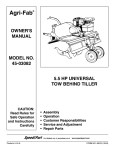
B
Owner's Manual
JCRRFTSHRN°I
6.5 HORSEPOWER
DO NOT RETURN TO STORE
For Missing Parts or Assembly
Questions Call 1-666-576-8388
36" TOW-BEHIND
UNIVERSAL TILLER
Model No. 486.252444
CAUTION:
Before using tt_ts product,
•
•
•
•
•
read
this manual anti follow all Safety
Rules and Ope_'ating Instructions.
Sears, Roebuck and Co,
www sears oorn/otaftsman
PRINTED IN U.S.A.:
Hoffman
Estates,
IL 60179
Safety
Assembly
Operation
Maintenance
Parts
U.S.A.
FORM NO. 49940 (2/06)
TABLE OF CONTENTS
SERVICE AND ADJUSTMENT ..................................... 11
WARRANTY ..................................................
_................. 2
STORAGE ..................................................................... 12
SAFETY RULES ......._..................................................... 3
TROUBLESHOOTING ................................................... 13
ASSEMBLY ..................................................................... 4
REPAIR PARTS ............................................................. 14
OPERATION ............. =..................................................... 6
PARTS ORDERING/SERVICE ........................ Rear Cover
MAINTENANCE ................. :............................................ 9
,
i
LIMITED WARR,_NTY ON CRAFTSMAN POWERED TRACTOR ATTACHMENTS
For one (1) year from the date of purchase, if this Craftsman Equipment Is maintained, lubricated and tuned
up according to the instructions in the owners manual, Sears will repair or replace free of charge any parts
found to be defe,_tive in material or workmanship. Warranty service is available free of charge by returning
your Craftsman _quipment to your nearest Sears Service Center. In-home warranty service is available but a
trip charge will al_ply.This Warranty applies only while this product is in the United States.
This Warranty does not cover:
• Expendable items which become worn during normal use, such as spark plugs, air cleaners, belts, and oil
filters.
• Tire replacement or repair caused by punctures from outside objects, such as nails, thorns, stumps, or
glass.
• Repairs necessary because of operator abuse, including but not limited to, damage caused by impacting
objects that bend the frame or crankshaft, or over-speeding the engine.
• Repairs necessary because of operator negligence, including but not limited to, electrical and mechanical
damage caused by improper storage, failure to use the proper grade and amount of engine oil, or f_ilure to
maintain the equipment according to the instructions contained in the owner's manual.
• Engine (fuel s_s_em) cleaning or repairs caused by fuel determined to be contaminated or oxidized (stele).
In general, fuel should be used within 30 days of its purchase date.
• Equipment used for commercial or rental purposes.
LIMITED WARRANTY ON BATTERY
For ninety (g0) d_ye from date of purchase, if any battery included with the equipment proves defective in
material or workmanship and our testing determines the batlery will not hold a charge, Sears will replace the
battery at no charge. Warren y service Is avenable tree of charge by returning your Craftsman equipment to
your nearest Se_rs Service Center. In-home warranty service is available but a trip charge will apply. This
Warranty applies only while this product is in the United States•
TO LOCATE THE NEAREST SEARS SERVICE CENTER OR TO SCHEDULE SERVICE.
SIMPLY CONTA(_T SEARS AT 1-800-4-MYoHOME.
This warranty giyes you specilic legal rights, and you may also have other rights, which vary from state to
state.
PRODUCT
Record serial numb0r and date of purchase in space
provided below.
MODEL
NUMBER:
486.252444
SERIAL
NUMBER:
SPECIFICATIONS
HORSEPOWER:
_ASOLINE TYPE
6.5 H.R
OILTYPE
SAE 30 (ABOVE 32 ° F)
REGULAR
UNLEADED
(API-SF/SG)
SAE 5W-30 (BELOW 320 F)
OIL CAPACITY:
20 07SPARK PLUG
(GAP .030")
TILLING GROUND SPEED Approx, 2 MPH
TILLING WIDTH
36 INCHES
DATE OF
PURCHASE:
The model and serial numbem will be found on a
plate attached to_theright hand chassis.
TILLING TINE SPEED
YOUshould record both serial number and date of
r
,
pumhase and keep ,n a safe place for future
reference.
2
200 RPM
WARNING:
This cutting machine
is oapable
ofresultin
amputating
hands
and feet
and throwing objects.Failure to
observe the followingsafety
instnJctions
could
sedous
injuryor
death.
IMPORTANT
Warnings, Cautions, _nd Notes are s means of attracting
attention to important,ororiUcal informationin this
manual.
41t
J A
safety precautions.It means-AttenUon!
Look
for this
symbolto
pointisout
important
Becomil
Alertl
Yoursafety
involved.
TRAINING
Read opening ana Service instructions carefully.Be
thoroughly familiar with the controls and the proper
use of the equipment.
Never allow children to operate the machine. Do not
allow adults to operate the machine without proper
instruction.
Keep the area of operation ctsar of all persons,
psrticularty small children and pets.
PREPARATION
•
•
•
Check the fuel and lubrication before starting the
engine. Do not fi!l the gasoline tank indoors when
the engine is running or while the engine is still hot.
Wipe off any spilled gasoline before starting the
engine.
Inspect the area:to be Uned.Remove glass, wire,
metal objects, lai'ge sticks, and stones. Avoid
underground pip,asand wiring.
Have a complete working knowledge of your tractor
and know how to handle your tractor with a tiller or
other attachment attached.
Stop engine end disconnect spark plug lead wire
before cleaning augers, removing obstacles, or
making adjustments, except for those which must
be done with the engine running.
Never place hands or feet under or into rotating
parts or concealed areas, Keep hands and feet
clearly away from auger elements, belts, pulleys,
etc. while engine is running,
Wear substantial shoes and eye protectionwhile
using tiller,
Never attempt to make a maintenance adjustment
while engine is running, except on the carburetor.
Do not run the engine indoors;carbon monoxide
fumes are dangerous to inhale.
Never operate machine without proper guards,
plates, or other safety protective devices in place.
Disengage the Tins Clutch Lever, stop tiller and
tractor engines before getting off the tractor.
Disengage the Tine Clutch Lever and stop the tiller
engine during transportationto and from the work
area.
MAINTENANCE AND STORAGE
Follow maintenance instructionsas outlined in this
manual and your Engine Owner's Manual supplied
with the unit.
Disconnect spark plug wire before making
maintenance adjustment or repair,
Store gasoline in an approved metal container in a
cool, dry place.
Safety and performance levels can be assured only,
by the use of specified replacement parts.
OPERATION
Give complete and undivided attention to the job at
hand. Operate tktetiller in daylightor good artificial
light.
Personal injurymay result from contact with the
augers or debris'thrownby this machine, Therefore,
always stay a safe distance away from the augers,
Stop the tiller engine when leaving your tiller
unattended.
Check before each use for loose fasteners or parts.
Never store the elquipmentwith gasoline in the tank
inside of a buildil_gwhere fumes may reach an open
flame or spark. Allow engine to cool before stodng in
an enolosure.
internsl combustion engine and should
WARNING:
is any
equipped
with an
not be usedThis
on orunit
near
unimproved
forest-ooveredor grass-coveredland
unlessthe engine's exhaust system is equipped with a
spark arrester meeting applicable localor state laws
(if any), If a spark attester is used, it shouldbe
maintained in effectiveworking order by the operator.
In the state of California, the above law is requiredby
law (Section 4442 of the California Public Resources
Code). Other states may have similar laws. Federal
laws apply on Federal lands.A spark attester for the
muffler is available through your nearest Sears
Authorized Service Center.
TO REMOVE UNIT FROM
CARTON
TO INSTALL THE TILLER
GAUGE WHEELS
•
•
Cut from top to bosom all four corners of the carton
and lay panels flat: (See Fig. 1)
Remove the lag screw that holds the floating hitchto
the packing skid. ,
• Disassemble and _llscsrd carton's wood top and side
supports.
• Remove four hex bolt, hex nuts and flat washer from
the hold down brackets at the rear of the carton,
Remove and save_thetwo Flat Washers and Cotter
Pins from the rear axle. Reuse when attaching gauge
wheels.
• Discard all other packing hardware end held down
brackets.
Assemble Gauge Wheels ontothe Rear Axle with the
extended end of Hub facinginward.Secure with the
Flat Washers end Cotter Pins which you removed from
the axle during unpacking,(See fig. 2.)
COTTEI
FLAT WASHER'
LAG SCREW
WOOD TOP
SUPPORTS
HOLD DOWN
BRACKET
FIG. 2
TO INSTALL THE TILLER TINE
ASSEMBLIES
WOOD SiDE
SUPPORTS
•
Attach the floating hitch to the tractor's draw bar.
(Refer to Operating Instructions on page 7.)
•
Remove the preassembled 3/8" x 2" hex bolt and 3/61'
nylocknut from the L.H. Tina Assembly.Slide the tine
assembly onto the TransmissionAxle on the left side
of the tiller and secure with the hex bolt and nylock
nut. (See fig. 3.) Repeat for the R.H. side.
HEX BOLT
PACKING HE}( NUT
SKID
FLAT WASHER
FIG, 1
Right hand (RH) and left hand (LH) are determined
from the ddvers positionwhile seated on the tractor_
•
We recommend that you remove the Mower Deck
before using the Tiller. Refer to your TractorOwner's
Manual,
CUTTING
EDGE
/ _/TRANSMISSION
3/8' x 2"
AXLE
HEX BOLT
FIG. 3
4
_
TO INSTAL L (WHEEL)
WEIGHTS TO TILLER
NOTE: Weights are riot furnished with the Tiller. 30 lb.
tractor wheel weights may be purchased to mount to the
Tiller if extra weight is required. (Refer to the Operation
section of this manual,)
•
Remove two Cam age Be ts and Nuts from each Tine
Shield, located approximately 3-1/2" from the front
edge. See fig. 4.
• Place (Wheel) Weights on Tine Shield and secure
with long Bolts and Nuts furnished with the Weights,
See fig. 4.
WHEEL
LONGI
)
/
"FINE
SHIELD
.NUT8
FIG. 4
KNOW YOUR TILLER
READ THIS OWNER'S MANUAL AND SAFETY RULESBEFORE OPERATINGYOUR TILLER.
Compare the Ulustral_ionswith yourtiller to familiarizeyourselfwith the location of variouscontrolsand
adjustments. Save the manual for futurereference_
RECOIL STARTER HANDLE
THROTrLE CONTROL
SAFETY SWITGH_
FUEL SHUT OFF
LOWER
CHOKE CONTROL
LIFT HANDLE,
RAISE'
EXTRA TINE BOLTS
ENGAGED
TINE CLUTCH LEVER.
•DEPTH STAKE
DISENGAGED
STAKE SUPPORT BRACKET
FLOATING HITCH
GUARD
'DEPTH ADJUSTMENT
TINE SHIELD
TINES
GAGE WHEELS
FIG. 5
SAFETY SWITCH - prevents engine from starting while
tine clutch lever is engaged
RECOIL START HANDLE - used to start the engine
THROTTLE CONTROL - controlsengine speed
LIFT HANDLE - seleqts tillingor transport positionby
moving gage wheels '
FUEL SHUT OFF - shuts of fuel to engine
"fiNE CLUTCH LEVER - starts and steps fine rotation
CHOKE CONTROL - used when starting a cold engine
FLOATING HITCH - (elescoping hil;chlimitsshook loads
to tractor
DEPTH STAKE - controlstilling/cultivatingdepth
Theoperationof anytillercanresult
In foreign objects thrown Into the eyes, which can
result in severe eye damage. Always wear safety glasses or eye shields before starting
your tiller end while tilling. We recommend a wide vision safety mask for over the
epsetacles or standard safety glasses.
HOW TO USE YOUR TILLER
Repeat instructionsin two preceding paragraphs until
engine fires.W_en engine starts, move choke control
graduallyto RUN position.
Allow engine to warm up for a few minutes before
engaging tines.
BEFORE STARTING YOUR TILLER
FILL THE ENGINE WITH OILI Yourtiller engine is
shipped without oil orlgasolins.Add oil and gas as
instructedIn the sepsrete engine manual.
ATTACHING
TILLER TO TRACTOR
(See Fig. 6)
with
the engine
running,or
while
the engine
WARNING:
Never
fill fuel tank
indoors,
or
is hot. Do not smoke while tiltingtank.
•
•
STOPPING
YOUR TILLER
TINES
•
Raise tiller to transportposition.
Pull forward on tins clutchlever.
.
Rear wheel weights end tire chains can be used on
tractor if additionaltraction is required for tilling.
Place Tiller on ground level and back up tractorto it.
Slide Floating Hitch of Tiller onto the tractor drawbar
so that the hitch pin holes line up.
Insert hitchpin until it extend,_through bottom of
Floating Hitch, Insert hair cotter pin into hitch pin.
ENGINE (Refer to separate engine manual.)
Move throttle controlto "STOP" position.
Turn shut off to "OFF" position.
•
Never use choke ;o stop engine.
STARTING
YOUR TILLER
(Refer to separate engine manuel.)
HITCH PIf
TRACTOR
DRAWBAR
i
CAUTION:
areas
are hotl
The muffler and adjacent
HAIR COI-rER PIN
•
•
•
•
°
Check oil and gas in Tiller engine.
Attach spark plug wire to spark plug.
Pull forward on tir_eclutch lever to disengage tines.
A safety switch preventsengine from starting while
tines are engaged.
Turn shut Offto "ON" position.
Move choke levei on engine to CHOKE position.
(A warm engine may not require choking.)
Move throttle controllever on engine to FAST
position.
Grasp starter handle and pull rope out slowly until
engine reaches start of compression cycle (rope will
pull slightly harder at this point).Let the rope rewind
slowly.
Pult rope with s r_pid, continuous,full arm stroke,
Keep a firm grip On starter handle. Let rope rewind
slowly.Do not let starter handle snap back against
starter.
FIG. 6
BREAKING IN YOUR TILLER
Break-in your belts, pulleys and the control before you
actually begin tilling.
•
Start engine with tiller attached to tractor in transport,
position.Engage Tins Clutch Lever to start tine
rotation.Allow tines to rotate for five minutes.
Check tins operation and adjust if necessary.See
"TINE OPERATION CHECK" in the Service and
Adjustmentssection of this manual.
TRANSPORTING
YOUR TILLER
•
AROUND THE YARI3
•
Pull forwardon lift handle until It looksIn the up,
transport poelUon.
.
AROUND TOWN
•
Dl=oonnectspa_ plug wlre.
•
Drain fuel tank.
•
"lT,,nsportin updght positionto preventoll leakage,
TO ADJUST DEPTH STAKE
•
•
e
•
Oepth stake has live po_tlon holesto eaJecttllllng
depth from I to 5 inches,
The top stake hole selectsthe shallowesitiling depth
and the bottom slake hole selects the deepest Ix_ltion.
To change depth'remove the hair cotter pin from the
clevis pin which Is connectingthe depth stake to the
stake supportbraokeL
Grasp the top ofthe depth stake, remove the clevis pin
and repositlonthe depth stake, insertclevis pin and
hair cotter pin.
IMPORTANT: THE DEPTH STAKE SHOULD NEVER BE
REMOVED FROM TIJE TILLER. IT IS DESIGNED TO
PROTECT THE TRACTOR TRANSAXLEFROM THRUSTING
ACTION OF THE TILLER.
TILLING
=
•
•
•
•
•
(Wh ) Weights.
The most eff_le_ tillage is obtained when THief
Engine Is oper=tKI at fullthro_e. The sound of the
Tiller Engine will tell you. When TigerEngJceIs
lightlyloaded, raise Gauge Wheels to Increasetilling
depth. If Engine,seems tO he ovedeaded or stalls OUt,
lower Gauge WheeJsfor shallowertilling.
Operate TillerEngine at full throttleand opsrato
tractor in slowesl forward speed,with tractor engine
at idle speed or Jbstabove idle. You _11 soon learn
the proper combinationOftilling depth and speed for
good tiflage.
Soil conditionsWilldetermine how deep Tiler can
penetrate on the]lrst pass. In extremelyhard
ground, several paLsee may be necessary to tillto a
depth of 6 inche,L.While in softground,Tdler may
penetrate to a dS_l_hof 6 inchesin the first pass.
TILLING
•
If the ego is eXtrerr_y hard and dry, it may be
desirabletO cross _l an area at shallow depthfirst,
then till In the directionof plantingrows on the
second pass at the 6naldepth.
Where po_ible, we recomrnendtilling in a pattern
similarto that shown In Fig. 7. Make the first peas,
then sldp a space equalto the width of the tiller,and
rcake the return pass. Then till the skipped area.
Tillingin thIs patternwillenable you to malmaln
better control, If the passeswere made side-by-side,
the tractor and ti_lerwo_Id tend to puntowardthe
tillt_d (eoft_side,
Check ground moisture: If you can make a ball in
your hand out of ground tO be tilled,do not till soilif
too wet. This _auBee lumpswhich ere difficultto
work up.
When operatingfor the first tirce, procaed slowlyand
carefully untilyou become farnlllarwith the proper
method of operatingthe _or.
In soil thin WZLS
tilledthe.year pefora, select the
tillingdepth at which the tiller engine runs
P_,omfo_d_yand does not Salt or pull down. Lower
depth for additlorwl passesffgreater depth is desired. ,
Whenever working multiple passes, go perpendicularto
the previous tiling direction.
!n ca.seewhere the soil Is too hard to get proper
penetration or if tJglngectlon causesTillerto hop or
bounce, It will be necessaryto purchasea =el OfTiller
CU LTIVATING
Yourtiller may be used for 0ultivating which requires
a minimum of two (2) inchesof soilpenetration.
Set depth stake $o the Tiller will penetratesoilto a
depth of 2 to 3 inches. The Tiller Engineshould be
run at fullthrottle _pt
when cultivadngsmall
plants. A slowerengine Is necessaryto prevent
buryingthe plants. (See fig. 8).
0©000
0000©
OOCO0
HINTS
OOCO0
IMPORTANT OPERATiNG HINTS
NOTE: The following isa general guidelineof tilling,
but may vary depending upon soil condl_ons.
•
In _r._._ egg.the _ler should be started In the
shallowestdepth position end lowered one positionat a
time aftereach pass in eaoh position.
l
FIG. "I
FIG.
8
GENERAL
•
RECOMMENDATIONS
The warranty on this Tiller does not cover itemsthat
have been subjected,to operator abuse or negllgence. To
receive fullvirus from the warranty, operator must
maintain unit as fnst_cted In thls
manuel
Once a year you should replacethe spark plug, clean Or
replaceair filter, and checktines and beltsfor wear.
A new spark plug and dean air filterassure prbperairfuel mixture and help your engine run better and last
longer.
BEFORE EACH USE
Some adjustments v_illneed to be made periodicallyto
prop¢ty maintain your unit,
All adjustments In th_ Service and Ad]ustmentssectionof
this manual should be checked at least once each season.
•
.
•
Check engine ORlevel.
Check tJneoperation,
Check for loose fastener_
LUBRICATION
Keep unitwell lubricated (Sea "LUBRICATIONCHART').
Refer to the engine manual for instructionson engine maintenance.
oort_olete
regularservice.
CheckEngineOil Levltl
/_Q_"//.(.,_/ "_
"_'_'/g_'_'/ _
X
ChangeEngineOil
X
Servlcesir oleaner precleaner
X"
X-
Serviceair cleanerca_t,'ridge
X-
Replacesparkplug
X
Cleancooling system
X"
Checkvalveclearance'
Checkfor loosefasteners
X
X
Lubdcste"l'ilier
_'ub ricateTillerTransmission
X
X'
"Change oil every 25;hours when operating the engine under heavy load or in high temperatures.
"Clean more oflen under dusty conditionsor when airborne debris is present. Replace air cleaner parts, if very dirly.
LUBRICATION CHART
(3_
REFER TO SEPARATE ENGINE OPERATING
& MAINTEN/_NCE INSTRUCTIONS
(_
REFER TO CU,STOMER RESPONSIBIUTIES
'TILLER LUBRICATION SECTION,"
_)
GENERAL PURPOSE GREASE
(_) TILLER
IMPORTANT: DO NbT OIL OR GREASE PIVOT POINTS.
VISCOUS LUBRICAt_JTS
WILL ATFRACTDUST AND DIRT
THAT CAN CAUSE WEAR ON PIVOT POINTS. IF YOU
FEEL THEY MUST BE LUBRICATED, USE ONLY A DRY
POWDERED GRAPHITE TYPE LUBRICANTS,
(_) TINE SHAFT
RG. 9
9
AXLESHAFT@!
TILLER LUBRICATION
CLEANING
Check transmissiondil level after first 5 hours of
operation.Remove Oil Fill Plug (Fig. 10). Oil Level must
be even with the Plug Hole (with Tiller level.) If necessary,
add Oil. Use SAE30 61on-DetergentMotor Oil. Replace
Oil Fill Plug,
•
Clean engine
manual.
•
Clean
wheels,
as instructed
finish,
etc.
in the engine
of all
fofelgn
matter.
•
•
Check transmission oil level after each 10 hours of
operation.
Keep finished surfaces and wheels free of
all gasoline, oil, etc.
Protect
painted
surfaces with automotivla
type wax.
We do not recommend
using a garden hose tb
clean your unit unless the muffler,
air fllte=r
and carburetor are covered to keep water out.
Water
in engine can result in e shortened
engine life.
NOTE: It is not neceslsaryto change the Oil in the Tiller
Transmission.If for any reason it must be changed, Oil
capacity is 22 oz.
MUFFLER
Do not operate tiller without muffler.
Do not
tamper with exhaust system. Damaged muffierls
or spark arresters could _reate
a fire hazard:.
Inspect periodically
and replace If necessary.
If your engine is equipped with a spark errester
screen assembly, remove every 50 hours four
cleaning and Inspection. Replace Ifdamaged.
FIG. 10
ENGINE MAINTENANCE
&
•
•
•
WARNING:
Always stop engine and
disconne(_tspark plug wire before cleaning,
lubricatingor before performingany repairs
or maintehanoe.
Check oil level b_fore each use and every 8 hours.
Maintain engine oil 8s instructed in the separate
engine manual.
Service air cleaner every 25 hours under normal
conditions.Clean,every few hours under extremely
dusty conditions.Poor engine performance and
flooding usually Jrtdlcatss that the air cleaner should
be serviced. To service the air cleaner, refer to the
separate engine manual,
Spark plug replacement is recommended every 100
hours or yearly.C,heckthe engine manual for correct
plug type and gap specifications.
10
BELT GUIDE
Clutch Le_'er the 1311erEngine and the Tractor
WARNINg: Shut off (disengage) the Tine
Engine bdfore making any repairs.
TRANSMISSION
PULLEY
CLUTCHING
PULLEY
ENGINE
PULLEY
TO REPLACE V-BELT
Replace V-belt if it h_ been dsmaged considerably from
slippingunder heavy !oads or ff it show cracks or frayed
edges. Refer to figures 11 and 12.
IMPORTANT: Do not move or remove the belt guide.
if the position of the Uelt guide is accidentally altered,
return it to the correct,setting(6-1/2' above the fine shield
support plate).
°
Remove the screw from the top of the belt guard,
Remove the hex hut from the rear of the guard.
Remove the belt guard to allow access to drive belt.
Disengage tine c!utchlever and remove belt.
Reverse above procedures for installationof new belt.
BELTROUTING
FIG. 12
BELT GUIDE
DRIVE BELT
SCREW
BELT GUARD
T
NUT
TINE SHIELD SUPPORT PLATE
FIG. 11
11
TINE SHIELD
SUPPORT
PLATE
SPARE TINE DRIVE BOLTS
Clutch Lever,the Tiller Engine and the Tractor
WARNINg: Shut off (disengage) thallne
Engine before making any repairs,
The Tiller ddve components are protected from
damage by (shearable) Grade 5 hex boltsin the
Tins Assemblies.The hex bolts drive the lines and
hold them in the proper location. Shouldthe Tins
Assemblies strike or pick up a large hiddenobject
or become jammed, the hex boltswill break and the
drive componentswill not be damaged.
TINE CARE
For best results--Tins Blades should be kept
reasonably sharp.The "line Blade can be sharpened
on a grinding wheel. Do not attempt to sharpen Tines
while they are mounted to Tiller.
Two extra tins hex belts and nuts are inoludedwith
the tiller.They are located in the Tiller Stake Support:
Bracket on the rear of the "1311er_
The tins hex bolts are designed to be loose fit. Do not
attempt to use a bolt or pin that Is tsrger or harder
than the original Grade 5 hex bolts.
Immediately prepare your tiller for storage at the end of
the season or if the uhit will not be used for 80 days or
more,
•
CAUTION; Never store the tiller with
&
•
gasolineIn the tank inside a building,
where fumes may reach an open flame
or spark.!AIIow the engine to cool before
storing in any enclosure.
•
•
ENGINE
Lubricate as instructedin the Customer
Responsibilitiessection of this manual.
Be sure that all nuts, boltsand screws are securely
fastened. Inspect moving parts for'damage, breakage
and wear, Replace if necessary.
Touch up all rusted or chippedpaint surfaces; sand
lightlybefore painting.
If possible, store tiller indoorsand cover It to protect
from dust and dirt.
Cover tiller with s suitable protective cover that does
not retain moisture,Do not use plastio.Plastis cennot
breathe, which allows condensationto form and will
cause your unitto rust.
Followthe instruc_tions
in the "Service& Storage"
sectionof the Engine Manual.
WARNING:
engine and exhaust
Never cover
areasTillerwhile
are stillwarm.
TILLER
Clean enUretilleri(See "CLEANING" in the Customer
Responsibilities_sction of the manual).
Inspect and replace belts, if necessary (See belt
replacement instr_Jclions in the Service and Adjustmanta section of this manual.
12
Follow the instructions in the 'Service & Storage" section of the
Engine Manual when performing any work on the Engine.
PRO'BLEM:
Probable Cause _-
PossibJeRemedy
WILL NOT START OR HARD TO START
No gasolinein Fuel Tank _.Choke not set ptopady
Throttle Control not set pmpedy
Choked improperly, flooded Engine _Dim/Air Cleaner
Loose Spark PlugWire
Spark Plug dirty or improper gap
Water In gasoline or old fuel
Clogged Fuel Tank
Fill tank with gasoline
Race Choke Control in "CHOKE" position
Race Throttte Control in "FAST"position
Move Choke controlto "RUN' position,place Thro_tleControl in
"FAST"positionand pull Starter severaltimes to clear oUt gas
Remove to Inspect, rel_ace ifdirty
Make sure Spark Plug Wire is seated properly on Spark Rug
Replace Spark Plug and adjust gap
Drain FuelTank and Carburetor, use freshfuel and replace Spark
Plug
Remove and dean
ENGINE MISSES OR LACKS POWER
Engine overloaded -_Partiallyplugged Air Cleaner _
DirtyAir Screen _
Spark Plug dirty, improper gap or wrong type _
Oil in gasoline _
Clogged FuelTank _
Poor ¢omlxession -----
Set Depth Stake end Wheels for shallower tilling
Remove and clean or replace
Clean AirScreen
Replace Spark Plug and adjust gap
Drain and refill gas Tank end Carburetor
Remove and clean
Major Engine overhaul
ENGINE OVERHEATS
Low oil level or dirty oil _
DirtyAir S,_rean_
Dim/Engine _
Partially Plugged Muffler _
EXCESSIVE
BOUNCE
Wheals and Depth:Stakeincorrectlyadjusted _
Groundtoo dr/and hard _
SOILBALLS
Groundtoo wet _
ENGINE
AND DIFFICULT
HANDLING
Adjust Whecls and Depth Stake
Moisten ground or walt for more favorable soil conditions
UP OR CLUMPS
Wait for more favorable soil conditions
RUNS WELL BUT TILLER WON'T MOVE
•Tine Control not engaged _
V-Belt offof pulleys -_-
ENGINE
Add or change oil
Clean Air Screen
Clean Cylinder Fins,Air Screen and Mufflerarea
Remove and clean Muffler
Engage Tins Control
Check V-Belt
RUNS WELL BUT LABORS WHEN TILLING
Tillingtoo deep _
Throttle Cohvol not properly adjusted _
Adjust Depth Stake
Check Throttle Control setting
,m
13
OC.
[_..r
m-o
o)
66
83--
r.
=3
39
'1
2O
61
14
69
17
\
62
26
16
23
-"
34
50
23
46
64
19 -'-_"
f
82
30
23
19 26
6.5 HPTOW BEHINDTILLER
MODEL 486.252444
Ref.
No.
Part
Number
Description
O_
Req.
;Engine
Guide - Bah
,_lolt,5/16=18 x 1-1/2 = Hex Head
.Screw,5/16-18 x 5/16 ° Gup Pt. Set
_<ey,_luafe 1/4" x 2"
pulley
!Nut, 1/2-12 Nyloek Jam
!Nut, 1#2-12 Hax Jam
_pdng, Dep_ Expand;ion
_Hitoh Snicker Assembly
IBolt, 5/16-t8 x t" Hex Head
Lod_ut, 5/16-18 H_
_LJftHandle As._err_ty
Screw, Scif.Tepping 1/4' x 1/2'
!Wastlar, 5/16' Std. WrL
:Ring, Rat=/net
',Pulley,Input
'Bolt - ShouJder
1
1
4
1
1
1
1
1
1
1
5
1
1
3
1
1
1
1
iNut, Hex Nylcek 1/4-20
Clutch Rc<l
.Switch, Safety Intedod<
'.Lever,Clutch
,Nut, Hex Nylock 3/6-16
_Gdp, Handle
,Rivet, Pop
,BraGke_,Belt Guide & Idler Mounting
'1SCreW, 5116.18 x 3/4' SelITtp
Bolt, 1/4.20 x 1" Hex Head
rK_y_Woodruff No. 61
Coven Drive
:Transmission• Complete
Chassis. Left
_pdng, ExtenSion
_Chassia, Right
IBraCket, Idler
!Pulley, Idler
V-Bait
:Nul, 1/4-20 Hex Leak
'Module
,_olt. 5/16-18 x 3/4" He= Hd.
_ear Guard Assembly - LH
Pin - Hair Cotter 5/32=
Rear Guard Assembly - RH
Tins & Hub Assembly - RH
Tins & Hub Assembly - LH
6
1
1
1
19
1
2
1
4
11
1
1
1
1
1
1
1
1
1
7
1
4
1
1
I
1
1
Ref.
No.
Part
Number
46
47
48
49
50
51
52
.5-3
54
55
56
57
58
59
SO
61
62
63
64
65
66
67
58
59
7O
71
72
73
74
75
76
77
78
79
60
81
82
83
84
NP
43054
47600
HA5236
43O62
HA20918
R74780828
HA20670
43350
HA20725
HA3433
HA20690
HA20932
HA20940
2583O
47810
41576
R74760884
44326
24849
HA14306
HA20691
712-3083
HA2093_
HA20942
HA5713
HA15200
712-0261
HA7274
48278
43010
HA,?.0688
HA19649
HA120396
HA124934
HA456151
HA20481
HA2.2594
HA22595
43178
40040
oty.i
Desoztptlotl
==
1
2
3
4
5
6
7
8
g
10
11
12
13
14
15
16
17
18
12
20
21
22
23
24
25
26
27
28
29
30
3t
32
33
34
35
36
37
35
39
40
41
42
43
44
4S
*Standatd
12130202B1E1
48348
43O85
HA115321
HA11154
HA20176
48733
HA124934
HA12_60
64282
43063
43064
64343
48840
43081
HA20135
HA20184
HA20178
47189
24848
HA23199
24847
HA21362
HA20170
C-9M5732
HA20134
HA9131
43661
HA201
24e63
HA2011 $
24843
HA20188
24844
24846
HAl1496
HA201e7
43013
64284
43162
HA20112
714-0117
HA20113
HA2.0094
HA20088
Hardware
- Pur_$ed
Locally
15
Bolt, 3]8-16 x 2"
Bolt, He.x5/16-24 _ 1"
Pin, Hitch
Bolt, 3!6-18 x 1-1/2' Hex Head
Wheel
Bodt.1/2-13 x 1-3/4" HeX Head
Pivot Axle Assembly
Bolt, 3/8.16 x 1" Cardage
ShOo Frame Extension
Pin, Clevis
Stake, Drag
Bracket - Wheel Weight Suppor_
Decal, Danger
Plate, Fender Support
NUt, Hex 5/16.18 Ny_
Bolt - 3/6-16 x 1-3/4" Hex He_d
Bolt. 1/2-13 x 5-1/2" Hex Head
Bolt,5/16=18 x 1" Ca_aga
Belt Guard (incl,#69)
Washer
$1rapFrame Cx_ansionBraes
Nut, 1/2-13 Nylock
D_:_1, Danger
Decal
Spacer
Washer
Nut, HOX5/16=11 Nyl0ck
Spear
Solt, He= 5/8-11 x 7-1/2 =
Pin • 1/8"x 1-114" Co_er
Rod - L.ift
Anchor- Adjustment
Washer - 17/32" x 1-1/8" _ .095" Flat
Nul - 112-20 Hex Jam
Washer • 13116"x 1-1/2" x .134" Flat
Pin - Hair Coltar
Shield, Tins (LH)
Shield. Tins (RH)
Nut, Hey 1/4-20
Owners Manual
4
1
1
1
2
1
1
8
2
2
1
2
1
1
18
5
1
2
1
1
1
3
2
1
1
2
1
2
1
6
1
1
5
1
4
2
1
1
1
1
REPAIR iPARTS FOR MODEL
2a
486.252444
6.5 HP TOW BEHIND TILLER
20
21
17
5
11
t2
I
24
9
23
13
12
7
6
4
3
2
Ref
No,
Part
Number
1
2
3
4
5
HA20344
43064
HA20123
HA,?.0122
43013
HA20120
HA2.0136
HA20127
HA20121
43866
HA20125
HA20124
HA20130
HA20129
HA20132
HA20128
HA2.0133
HA20131
HA20135
43012
HA20137
HA20145
HA20155
HA20138
Qty.
Req,
Desoription
..
6
7
8
9
10
11
12
13
14
15
16
17
18
19
20
21
22
23
24
,
m
.
.
Dust Cap
Locknut,5/16-18 *
Flange & Bearing Assy
Gasket, Flange
Locknut,1/4-20 Hex *
Drive Housing & Bearing Assy - LH
Gasket, Drive Housing
Tine Shaft Assy
Drive Housing & Bearing Assy - RH
Bolt, Hex 1/4-20 x 5/8" Grade 8
Washer, Feb
Seal, Rubber
Plug, TransmissionOil
Washer, Thrust
Chain Assembly #40
Chain Assembly #50
Input Shaft Assembly
Idler Shaft Assembly
Ring, Retainer 5/8" Dia. Shaft
Belt - 1/4-20 x 3/4" Hex Head "
Bearing
Seal
Bearing, Flange
Cap, Bearing
"8k_ndard Hardware - Purchased LocaJly
16
It
2
8
2
2
17
1
1
1
1
15
2
2
1
4
1
1
1
1
1
2
4
1
2
3
1
NOTES
17
NOTES
t
18
f
NOTES
19
Your Home
7
For repair-in
your home-of
all major brand appliances,
lawn and garden equipment, or heating and cooling systems,
no matter who made it, no matter who sold itl
For the replacement parts, accessories and
owner's manuals that you need to do-it-yourself.
For Sears professional installation of home appliances
and items like garage door openers and water heaters.
1-800-4-MY-HOME
Call anytime,
,i'i_
I
®
(1-800.469.46e3)
day or night (U.S.A.
www, sears.com
and Canada)
www.sears.ce
Our Home
For repair of carry-in items like vacuums, lawn equipment,
and' electronics, call or go on-line for the location of your nearest
Sears
,
,%
Parts & Repair Center.
1-800-488-1222
Call anytime, day or night (U.S.A. only)
www.sears.com
flI.
To purchase a protection agreement (U.S.A.)
or maintenance agreement (Canada) on a product serviced by Sears:
1-800-827-6655
(U.S.A.)
Para _edir servicio de reparacibn
a domicilio, y para ordenar piezas:
1_-888-SU-HOGAR
1-800-361-6665
AU Canada
® Registered T_dernad(
I TM Traden_rk
pour service en frangais:
1-800-LE-FOYER
®
(1-888-784-6427)
" '..... i"_"_J: ..........:"_:i:;,
(Canada)
"c
(1-800-533-6937)
www.sears,ca
Sears
/ _M Se_'ice Mad( of Seam Brands, LLC
@Mama Reg_stRlcla
/ 11.t Marca de F;lbrlea/ aM Marca de Serv_o OeSears 8ran(l_, LLC
MoMm_iue de _mmeme/'_a M_lrque_l_posee_e 8cans Brenda,LLC
@8eara Bran_s, LI.C
'1