1
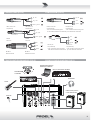
Mi6
6-CH 2-BUS MIXER
USER MANUAL
MANUALE D'USO
FCC COMPLIANCE NOTICE
This device complies with part 15 of the FCC rules. Opera on is subject to the following two condi ons:
(1) This device may not cause harmful interference, and
(2) this device must accept any interference received, including interference that may cause undesired opera on.
CAUTION: Changes or modifica ons not expressly approved by the party responsible for compliance could void
the user’s authority to operate the equipment.
NOTE: This equipment has been tested and found to comply with the limits for a Class B digital device, pursuant to
part 15 of the FCC Rules. These limits are designed to provide reasonable protec on against harmful interference in
a residen al installa on. This equipment generates, uses, and can radiate radio frequency energy and, if not installed
and used in accordance with the instruc on manual, may cause harmful interference to radio communica ons.
However, there is no guarantee that interference will not occur in a par cular installa on. If this equipment does
cause harmful interference to radio or television recep on, which can be determined by turning the equipment off
and on, the user is encouraged to try to correct the interference by one or more of the following measures:
• Reorient or relocate the receiving antenna.
• Increase the separa on between the equipment and receiver.
• Connect the equipment into an outlet on a circuit different from that to which the receiver is connected.
• Consult the dealer or an experienced radio/TV technician for help.
This marking shown on the product or its literature, indicates that it should not be disposed with other household wastes at the end of
its working life. To prevent possible harm to the environment or human health from uncontrolled waste disposal, please separate this
from other types of wastes and recycle it responsibly to promote the sustainable reuse of material resources. Household users should
contact either the retailer where they purchased this product, or their local government office, for details of where and how they can
take this item for environmentally safe recycling. Business users should contact their supplier and check the terms and condi ons of the
purchase contract. This product should not be mixed with other commercial wastes for disposal.
The lightning flash with arrowhead symbol within an equilateral triangle is intended to alert the user to the presence of uninsulated
“dangerous voltage” within the product’s enclosure, that may be of sufficient magnitude to cons tute a risk of electric shock to persons.
The exclama on point within an equilateral triangle is intended to alert the user to the presence of important opera ng and maintenance
(servicing) instruc ons in the literature accompanying the appliance.
The informa on contained in this publica on has been carefully prepared and checked. However no responsibility will be taken for any errors. All
rights are reserved and this document cannot be copied, photocopied or reproduced in part or completely without wri en consent being obtained
in advance from PROEL. PROEL reserves the right to make any aesthe c, func onal or design modifica on to any of its products without any prior
no ce. PROEL assumes no responsibility for the use or applica on of the products or circuits described herein.
Il marchio riportato sul prodo o o sulla documentazione indica che il prodo o non deve essere smal to con altri rifiu domes ci al
termine del ciclo di vita. Per evitare eventuali danni all’ambiente si invita l’utente a separare questo prodo o da altri pi di rifiu e di
riciclarlo in maniera responsabile per favorire il riu lizzo sostenibile delle risorse materiali. Gli uten domes ci sono invita a conta are
il rivenditore presso il quale è stato acquistato il prodo o o l’ufficio locale preposto per tu e le informazioni rela ve alla raccolta
differenziata e al riciclaggio per questo po di prodo o. Gli uten aziendali sono invita a conta are il proprio fornitore e verificare i
termini e le condizioni del contra o di acquisto. Questo prodo o non deve essere smal to unitamente ad altri rifiu commerciali.
Il simbolo del lampo con freccia in un triangolo equilatero intende avver re l'u lizzatore per la presenza di "tensioni pericolose" non isolate
all'interno dell'involucro del prodo o, che possono avere una intensità sufficiente a cos tuire rischio di scossa ele rica alle persone.
Il punto esclama vo in un triangolo equilatero intende avver re l'u lizzatore per la presenza di importan istruzioni per l'u lizzo e la
manutenzione nella documentazione che accompagna il prodo o.
Le informazioni contenute in questo documento sono state a entamente reda e e controllate. Tu avia non è assunta alcuna responsabilità per
eventuali inesa ezze. Tu i diri sono riserva e questo documento non può essere copiato, fotocopiato, riprodo o per intero o in parte senza
previo consenso scri o della PROEL. PROEL si riserva il diri o di apportare senza preavviso cambiamen e modifiche este che, funzionali o di
design a ciascun proprio prodo o. PROEL non assume alcuna responsabilità sull’uso o sul l’applicazione dei prodo o dei circui qui descri .
INDEX
INDICE
FCC COMPLIANCE NOTICE . . . . . . . . . . . . . . . . . . .
TECHNICAL SPECIFICATIONS . . . . . . . . . . . . . . . . .
CONTROL PANEL (FIG.1) . . . . . . . . . . . . . . . . . . . . .
CONNECTIONS (FIG.2) . . . . . . . . . . . . . . . . . . . . . .
CONFIGURATION EXAMPLES (FIG.3) . . . . . . . . . . .
ENGLISH LANGUAGE. . . . . . . . . . . . . . . . . . . . . . . .
SAFETY AND PRECAUTIONS . . . . . . . . . . . . . . . . . .
IN CASE OF FAULT . . . . . . . . . . . . . . . . . . . . . . . . . .
CE CONFORMITY . . . . . . . . . . . . . . . . . . . . . . . . . . .
PACKAGING, SHIPPING AND COMPLAINT . . . . . . .
WARRANTY AND PRODUCTS RETURN . . . . . . . . . .
INSTALLATION AND DISCLAIMER . . . . . . . . . . . . . .
POWER SUPPLY AND MAINTENANCE . . . . . . . . . .
GENERAL INFORMATION . . . . . . . . . . . . . . . . . . . .
OPERATING INSTRUCTIONS (FIG. 1 / 2 / 3) . . . . . .
2
3
4
5
5
6
6
6
6
6
6
6
6
7
7
TECHNICAL SPECIFICATIONS
MODEL
SPECIFICHE TECNICHE . . . . . . . . . . . . . . . . . . . . . . 3
PANNELLO DI CONTROLLO (FIG.1) . . . . . . . . . . . . . 4
CONNESSIONI (FIG.2) . . . . . . . . . . . . . . . . . . . . . . . 5
ESEMPI CONFIGURAZIONI (FIG.3) . . . . . . . . . . . . . 5
LINGUA ITALIANA . . . . . . . . . . . . . . . . . . . . . . . . . . 9
AVVERTENZE PER LA SICUREZZA . . . . . . . . . . . . . . 9
IN CASO DI GUASTO . . . . . . . . . . . . . . . . . . . . . . . . 9
CONFORMITÀ CE . . . . . . . . . . . . . . . . . . . . . . . . . . . 9
IMBALLAGGIO, TRASPORTO E RECLAMI . . . . . . . . 9
GARANZIE E RESI . . . . . . . . . . . . . . . . . . . . . . . . . . 9
INSTALLAZIONE E LIMITAZIONI D’USO . . . . . . . . . . 9
ALIMENTAZIONE E MANUTENZIONE . . . . . . . . . . . 9
INFORMAZIONI GENERALI . . . . . . . . . . . . . . . . . . 10
ISTRUZIONI OPERATIVE (FIG. 1 / 2 / 3) . . . . . . . . 10
SPECIFICHE TECNICHE
Mi6
Connectors
MODELLO
MONO INPUT CHANNELS
Mic Input Sensi vity
from -10 to -50 dBu
Mic Input Impedance
2 Kohm
Line Input Sensi vity
from +20 to -20 dBu
Line Input Impedance
10 Kohm
EQ HIGH (shelving)
EQ LOW (shelving)
Balanced XLR-F
Balanced Jack
from -10 to -50 dBu
Impedenza Ingresso Mic
2 Kohm
Sensibilità Ingresso Line
from +20 to -20 dBu
Impedenza Ingresso Line
10 Kohm
EQ ALTI (shelving)
±15 dB @ 80Hz
EQ BASSI (shelving)
STEREO INPUT CHANNELS
Line Input Sensi vity
-10 dBu
10 Kohm
XLR-F Bilanciato
Jack Bilanciato
±15 dB @ 12KHz
±15 dB @ 80Hz
CANALI INGRESSO STEREO
Balanced Jack
Sensibilità Ingresso Line
-10 dBu
Impedenza Ingresso Line
10 Kohm
MASTER SECTION
MAIN MIX nom. out level
Conne ori
CANALI INGRESSO MONO
Sensibilità Ingresso Mic
±15 dB @ 12KHz
Line Input Impedance
Mi6
Jack Bilanciato
SEZIONE MASTER
+4 dBu
Balanced Jack
Livello nom. MAIN MIX
+4 dBu
Jack Bilanciato
2 - TRK nom. out level
0 dBu
Unbalanced Rca
Livello nom. 2 - TRK OUT
0 dBu
Rca Sbilanciato
2 - TRK nom. in level
0 dBu
Unbalanced Rca
Livello nom. 2 - TRK IN
0 dBu
Rca Sbilanciato
PHONES min. impedance
PHONES max. out level
32 ohm
Stereo Jack
(2x) 193 mW
Impedenza min. PHONES
Livello max. PHONES
GENERAL SPECIFICATIONS
Max level all outputs
+22 dBu
32 ohm
SPECIFICHE GENERALI
Livello Massimo Uscite
+22 dBu
Crosstalk meas. at 1 KHz
> 82 dBu
Diafonia mis. a 1 KHz
> 82 dBu
HUM & N unweighted
< -93 dBu
HUM & N non pesato
< -93 dBu
THD+N at +4dB, 1kHz
Dimensions (W x H x D)
Weight
< 0,01 %
THD+N a +4dB, 1kHz
< 0,01 %
173 x 222 x 60 mm
Dimensioni (L x A x P)
173 x 222 x 60 mm
1.00 kg
Peso
POWER REQUIREMENTS
Supply
Mains Supply Voltage,
see label on the AC/AC
ADAPTER, available for:
18VAC 500mA use only supplied AC/AC ADAPTER
110-120 VAC (±10%) 50 / 60 Hz (US plug)
230-240 VAC (±10%) 50 / 60 Hz (EU plug)
240 VAC (±10%) 50 / 60 Hz (UK plug)
Consump on
17 VA
Jack Stereo
(2x) 193 mW
1.00 kg
ALIMENTAZIONE
Alimentazione
Tensione di Rete,
vedi l'e che a sull' AC/
AC ADAPTER, disponibile
per:
Assorbimento
18VAC 500mA usare solo AC/AC ADAPTER incluso
110-120 VAC (±10%) 50 / 60 Hz (US plug)
230-240 VAC (±10%) 50 / 60 Hz (EU plug)
240 VAC (±10%) 50 / 60 Hz (UK plug)
17 VA
3
CONTROL PANEL (FIG.1)
PANNELLO DI CONTROLLO (FIG.1)
9
10
1
13
14
20
2
3
18
23
4
24
15
5
6
22
11
21
7
16
19
8
17
12
25
26
27
4
CONNECTIONS (FIG.2)
CONNESSIONI (FIG.2)
Ɵp - hot
Ɵp - hot
ring - cold
cold
ground
sleeve - ground
LINE IN, various OUT
LINE IN, OUT vari
LINE IN, various OUT
LINE IN, OUT vari
Jack (balanced)
Jack (bilanciato)
Jack (unbalanced)
Jack (sbilanciato)
Ɵp - leŌ
*note: connect both cold and ground
*nota: conneƩere insieme cold e ground
to make cable from balanced to unbalanced per cavi da bilanciato a sbilanciato
ring - right
sleeve - ground
PHONES
PHONES
Stereo Jack
Jack stereo
hot
cold
ground
hot
cold
ground
MIC INPUT
MIC INPUT
Balanced male XLR
XLR bilanciato maschio
CONFIGURATION EXAMPLES (FIG.3)
2TRK IN, OUT
2TRK IN, OUT
Jack (unbalanced)
Jack (sbilanciato)
*note: connect both cold and ground to
*nota: conneƩere insieme cold e ground
make cable from balanced to unbalanced per cavi da bilanciato a sbilanciato
ESEMPI CONFIGURAZIONI (FIG.3)
PERSONAL COMPUTER WITH
AUDIO IN/OUT CAPABILITY
MP3 / CD / DVD PLAYER - RECORDER
DRUM MACHINE
or KEYBOARD
HEADPHONES
GUITAR
FLASH5A desktop monitors
or other AUDIO SYSTEM
VOCAL MIC
5
ENGLISH LANGUAGE
SAFETY AND PRECAUTIONS
•
CAUTION: before using this product read carefully the following safety instruc ons. Take a look of this manual en rely and preserve it for
future reference.
When using any electric product, basic precau ons should always be taken, including the following:
– To reduce the risk, close supervision is necessary when the product is used near children.
– Protect the apparatus from atmospheric agents and keep it away from water, rain and high humidity places.
– This product should be site away from heat sources such as radiators, lamps and any other device that generate heat.
– Care should be taken so that objects and liquids do not go inside the product.
– The product should be connected to a power supply mains line only of the type described on the opera ng instruc ons or as marked on the
product. Connect the apparatus to a power supply using only power cord included making always sure it is in good condi ons.
–
WARNING: The mains plug is used as disconnect device, the disconnect device shall remain readily operable.
– Power supply cord should be unplugged from the outlet during strong thunderstorm or when le unused for a long period of me.
– Do not place objects on the product’s power cord or place it in a posi on where anyone could trip over, walk on or roll anything over it. Do not
allow the product to rest on or to be installed over power cords of any type. Improper installa ons of this type create the possibility of fire hazard
and/or personal injury.
IN CASE OF FAULT
•
–
–
–
–
–
•
In case of fault or maintenance this product should be inspected only by qualified service personnel when:
There is a flaw either in the connec ons or in the supplied connec ng cables.
Liquids have spilled inside the product.
The product has fallen and been damaged.
The product does not appear to operate normally or exhibits a marked change in performance.
The product has been lost liquids or gases or the enclosure is damaged.
Do not operate on the product, it has no user-serviceable parts inside, refer servicing to an authorized maintenance centre.
CE CONFORMITY
• Proel products comply with direc ve 2004/108/EC (EMC), as stated in EN 55013 standard and with direc ve 2006/95/CE (LVD), as stated in EN
60065 standard.
• Under the EM disturbance, the ra o of signal-noise will be changed above 10dB.
PACKAGING, SHIPPING AND COMPLAINT
• This unit package has been submi ed to ISTA 1A integrity tests. We suggest you control the unit condi ons immediately a er unpacking it.
• If any damage is found, immediately advise the dealer. Keep all unit packaging parts to allow inspec on.
• Proel is not responsible for any damage that occurs during shipment.
• Products are sold “delivered ex warehouse” and shipment is at charge and risk of the buyer.
• Possible damages to unit should be immediately no fied to forwarder. Each complaint for package tampered with should be done within eight
days from product receipt.
WARRANTY AND PRODUCTS RETURN
• Proel products have opera ng warranty and comply their specifica ons, as stated by manufacturer.
• Proel warrants all materials, workmanship and proper opera on of this product for a period of two years from the original date of purchase. If
any defects are found in the materials or workmanship or if the product fails to func on properly during the applicable warranty period, the owner
should inform about these defects the dealer or the distributor, providing receipt or invoice of date of purchase and defect detailed descrip on.
This warranty does not extend to damage resul ng from improper installa on, misuse, neglect or abuse. Proel S.p.A. will verify damage on returned
units, and when the unit has been properly used and warranty is s ll valid, then the unit will be replaced or repaired. Proel S.p.A. is not responsible
for any "direct damage" or "indirect damage" caused by product defec veness.
INSTALLATION AND DISCLAIMER
• Proel products have been expressly designed for audio applica on, with signals in audio range (20Hz to 20kHz). Proel has no liability for damages
caused in case of lack of maintenance, modifica ons, improper use or improper installa on non-applying safety instruc ons.
• Proel S.p.A. reserves the right to change these specifica ons at any me without no ce.
• Proel S.p.A. declines any liability for damages to objects or persons caused by lacks of maintenance, improper use, installa on not performed
with safety precau ons and at the state of the art.
POWER SUPPLY AND MAINTENANCE
• Clean only with dry cloth.
• Before connec ng the product to the mains outlet make certain that the mains line voltage matches that shown on the rear of the product, a
tolerance of up to ±10% is acceptable.
6
GENERAL INFORMATION
Thank you for having chosen a PROEL product.
The new Mi Series has been created by PROEL in order to offer very compact mixers with a high input density at a very
affordable price. The series includes 3 models with 6, 10 and 12 channels, featuring in a very compact package a high
number of inputs and a full set of intelligent features, able to sa sfy most of the sound reinforcement applica ons.
The Mi6 offers in a ultra-compact format the sound and the quality of large professional consoles, delivering a clean
and accurate sound and full mixing capability in a stylish and unconven onal case.
OPERATING INSTRUCTIONS (FIG. 1 / 2 / 3)
1. MIC Input
This is a female XLR connector, which accepts a balanced microphone input from almost any type of microphone. The
XLR inputs are wire as follows:
Pin 1 = shield or ground
Pin 2 = + posi ve or "hot"
Pin 3 = - nega ve or "cold"
2. LINE Input
This is a ¼” (6.3mm) jack connector, which accepts a balanced or unbalanced line level input signal from almost any
source. When connec ng a balanced signal, wire them as follows:
Tip = + posi ve or "hot"
Ring = - nega ve or "cold"
Sleeve = shield or ground
When connec ng an unbalanced signal, wire them as follows:
Tip = + posi ve or "hot"
Sleeve = shield or ground
3. GAIN Control
The gain control adjusts the input sensi vity of the mic and line inputs. This allows the signal from mics and instruments
to be adjusted to op mal internal levels. If the signals are plugged into the XLR input there is a 10 dB of gain with the
knob turned all way down, ramping up to 50 dB of gain fully up. When connected to the jack input, there is 20 dB of
a enua on all way down and 20 dB of gain fully up, with a unity gain (0 dB) if centered.
4. EQ sec on HIGH control
This control gives you up to 15dB boost or cut at 12KHz with a "SHELVING" curve shape. Use it to increase or reduce
the sound "clarity" or "brightness".
5. EQ sec on LOW control
This control gives you up to 15dB boost or cut at 80Hz with a "SHELVING" curve shape. Use it to increase or reduce the
sound "punch".
6. PAN control
It adjusts the amount of channel signal sent to the le versus the right outputs. Use it to posi on the signal in a
panoramic stereo scene.
7. PEAK detector
The PEAK LED flashes when the input signal is near to the CLIPPING point. IMPORTANT: if the LED PEAK flashes reduce
the level of the input signal using the GAIN control.
8. FADER LEVEL control
It adjusts the level of the channel 1 or 2 signal and send it to the MAIN MIX outputs.
9. LINE 3/4 LEFT/MONO Input
This is a female JACK connector, which accepts a balanced or unbalanced line level input signal from almost any source.
If the RIGHT jack is not inserted, this channel operate like a MONO channel with this input as a single signal source.
Wiring is the same of point 2.
10. LINE 4 RIGHT Input
This is a JACK connector, which accepts a balanced or unbalanced line level input signal from almost any source. This is
used only in presence of LEFT jack input to use the channel as STEREO.
11. BAL control
It adjusts the amount of channel signal sent to the le versus the right outputs if the channel is used as MONO, or it
fades the LEFT or RIGHT signal amount if the channel is used as STEREO.
7
12. FADER LEVEL control
It adjusts the level of the channel 3/4 signal and send it to the MAIN MIX outputs.
13. 2TRK 5/6 Inputs
Use these unbalanced RCA connectors to patch the output of a player, such as an analog tape deck, MP3 player, CD/DVD
player or a Personal Computer.
14. 2TRK Output
Use these unbalanced RCA connectors to send out the MAIN MIX signal to a recorder, such as an analog tape or an A/D
converter connected to a Personal Computer.
15. TO MIX / TO PHONES switch
Use this switch to route the signal coming from 2TRK input to MAIN MIX or to PHONES only.
16. BAL control
It fades the LEFT or RIGHT signal of 2TRK 5/6 channels amount to the MAIN MIX outputs.
17. 2TRK 5/6 IN LEVEL control
It adjust the level of the 2TRK 5/6 channel and send it to the MAIN MIX outputs.
18. MAIN MIX L & R jack output (balanced)
These JACK connectors (+4dBu) provide a balanced line level signal from the MAIN MIX stereo bus.
NOTE: the MAIN OUT is a true balanced output that can send the signal on a balanced line with or without a phantom
power acƟve. So the Mi6 can also be used as a combinaƟon mixer + DI box for sending the signals to a bigger main
mixer console.
19. MAIN MIX FADER control
The MAIN MIX FADER controls the output level just before the MAIN MIX outputs and the 2TRK outputs. When the
fader is fully down the MAIN MIX is off , the "0" marking indicates a +4dBu nominal output level. Typically this fader is
set near the "0" label and le alone, but it can be used for song fadeouts or quick system-wide mutes.
20. PHONES stereo jack output
STEREO JACK connector for the headphones output: only stereo headphones with a minimum impedance of 32 Ohms
should be connected to this output.
21. PHONES LEVEL control
This controls the PHONES output's level. The signal at this output is the same as at the MAIN MIX or 2TRK Input.
22. L & R LEVEL METERS
The level meters are made of two columns of four LEDs with three colours, to indicate different ranges of signal level:
• green = shows the normal opera ve level of the signal (from -20 to 0 dBpeak)
• yellow = shows the nominal opera ve level of the signal (from 0 to +6 dBpeak)
• red = shows a high signal level (near +20 dBpeak CLIP level).
23. +48V phantom switch
This switch ac vates (LED on) and deac vates (LED Off) the phantom power on MIC Inputs. Most professional condenser
microphones require phantom power, which is a lower DC voltage delivered to the microphone on pin 2 and 3 of the
XLR microphone connector. Dynamic microphones do not require phantom power, however phantom power will not
harm most dynamic microphones should you plug one in while the phantom power is on. Check the manual of your
microphone to find out for sure whether or not phantom power can damage it.
24. ON led
Indicates when the mixer is switched on.
25. 18V~ socket
Here’s where you plug in your mixer’s external power supply. You should always connect your power supply to the mixer
before you plug the power supply into an electrical outlet.
26. POWER switch
Switch this one on and your mixer has power. Switch it off and it doesn’t. Make sure that all master output knobs are
turned all the way down when powering your mixer up or down.
27. PRODUCT LABEL
In this label are wri en the most important informa on about the mixer, model, line voltage, consump on, serial
number.
8
LINGUA ITALIANA
AVVERTENZE PER LA SICUREZZA
•
ATTENZIONE: Durante le fasi di uso o manutenzione, devono essere prese alcune precauzioni onde evitare danneggiamen alle stru ure
meccaniche ed ele roniche del prodo o.
Prima di u lizzare il prodo o, si prega di leggere a entamente le seguen istruzioni per la sicurezza. Prendere visione del manuale d’uso e
conservarlo per successive consultazioni:
– In presenza di bambini, controllare che il prodo o non rappresen un pericolo.
– Posizionare l’apparecchio al riparo dagli agen atmosferici e a distanza di sicurezza dall’acqua, dalla pioggia e dai luoghi ad alto grado di
umidità.
– Collocare o posizionare il prodo o lontano da fon di calore quali radiatori, griglie di riscaldamento e ogni altro disposi vo che produca
calore.
– Evitare che qualsiasi ogge o o sostanza liquida entri all’interno del prodo o.
– Il prodo o deve essere connesso esclusivamente alla rete ele rica delle cara eris che descri e nel manuale d’uso o scri e sul prodo o,
usando esclusivamente il cavo rete in dotazione e controllando sempre che sia in buono stato, in par colare la spina e il punto in cui il cavo esce
dal prodo o.
–
ATTENZIONE: Se il cavo rete viene scollegato dall'apparecchio per spegnerlo, il cavo rete rimarrà opera vo in quanto la sua spina è ancora
collegata alla rete ele rica.
– Disconne ere il prodo o dalla rete ele rica durante for temporali o se non viene usato per un lungo periodo di tempo.
– Non disporre ogge sul cavo di alimentazione, non disporre i cavi di alimentazione e segnale in modo che qualcuno possa incianparci. Altresì
non disporre l’apparecchio sui cavi di altri appara . Installazioni inappropriate di questo po possono creare la possibilità di rischio di incendio
e/o danni alle persone.
IN CASO DI GUASTO
•
–
–
–
–
–
•
In caso di guasto o manutenzione questo prodo o deve essere ispezionato da personale qualificato quando:
Ci sono dife sulle connessioni o sui cavi di collegamento in dotazione.
Sostanze liquide sono penetrate all’interno del prodo o.
Il prodo o è caduto e si è danneggiato.
Il prodo o non funziona normalmente esibendo una marcato cambio di prestazioni.
Il prodo o perde sostanze liquide o gassose o ha l’involucro danneggiato.
Non intervenire sul prodo o. Rivolgersi a un centro di assistenza autorizzato Proel.
CONFORMITÀ CE
• I Prodo Proel sono conformi alla dire va 2004/108/EC (EMC), secondo lo standard EN 55013 ed alla dire va 2006/95/CE (LVD), secondo lo
standard EN 60065.
• Se so oposto a disturbi EM, il rapporto segnale-rumore può essere superiore a 10dB.
IMBALLAGGIO, TRASPORTO E RECLAMI
• L’imballo è stato so oposto a test di integrità secondo la procedura ISTA 1A. Si raccomanda di controllare il prodo o subito dopo l’apertura
dell’imballo.
• Se vengono riscontra danni informare immediatamente il rivenditore. Conservare quindi l’imballo completo per perme erne l’ispezione.
• Proel declina ogni responsabilità per danni causa dal trasporto.
• Le merci sono vendute “franco nostra sede” e viaggiano sempre a rischio e pericolo del distributore.
• Eventuali avarie e danni dovranno essere contesta al ve ore. Ogni reclamo per imballi manomessi dovrà essere inoltrato entro 8 giorni dal
ricevimento.
GARANZIE E RESI
• I Prodo Proel sono provvis della garanzia di funzionamento e di conformità alle proprie specifiche, come dichiarate dal costru ore.
• La garanzia di funzionamento è di 24 mesi dopo la data di acquisto. I dife rileva entro il periodo di garanzia sui prodo vendu , a ribuibili a
materiali dife osi o dife di costruzione, devono essere tempes vamente segnala al proprio rivenditore o distributore, allegando evidenza scri a
della data di acquisto e descrizione del po di dife o riscontrato. Sono esclusi dalla garanzia dife causa da uso improprio o manomissione. Proel
SpA constata tramite verifica sui resi la dife osità dichiarata, correlata all’appropriato u lizzo, e l’effe va validità della garanzia; provvede quindi
alla sos tuzione o riparazione dei prodo , declinando tu avia ogni obbligo di risarcimento per danni dire o indire eventualmente derivan
dalla dife osità.
INSTALLAZIONE E LIMITAZIONI D’USO
• I Prodo Proel sono des na esclusivamente ad un u lizzo specifico di po sonoro: segnali di ingresso di po audio (20Hz-20kHz). Proel declina
ogni responsabilità per danni a terzi causa da mancata manutenzione, manomissioni, uso improprio o installazione non eseguita secondo le
norme di sicurezza.
• La Proel S.p.a. si riserva di modificare il prodo o e le sue specifiche senza preavviso.
• Proel declina ogni responsabilità per danni a terzi causa da mancata manutenzione, manomissioni, uso improprio o installazione non eseguita
secondo le norme di sicurezza e a regola d'arte.
ALIMENTAZIONE E MANUTENZIONE
• Pulire il prodo o unicamente con un panno asciu o.
• Prima di collegare l'apparecchio alla presa di corrente, accertatevi che la tensione di rete corrisponda a quella indicata sul retro dell’apparato, è
consen to un margine del ±10% rispe o al valore nominale.
9
INFORMAZIONI GENERALI
Grazie per aver scelto un prodo o PROEL.
La nuova serie Mi è stata creata da PROEL per fornire mixer molto compa con un gran numero di ingressi ad un prezzo
conveniente. La serie include 3 modelli con 6, 10 e 12 canali i quali offrono, in dimensioni estremamente compa e,
un elevato numero di ingressi ed un set completo di funzioni intelligen e sono in grado di soddisfare le più svariare
applicazioni di sound reinforcement.
Il mixer Mi6 offre in un formato ultra-compatto possibilità di missaggio avanzate con la qualità delle consolle
professionali e con un design di s le non convenzionale.
ISTRUZIONI OPERATIVE (FIG. 1 / 2 / 3)
1. MIC (ingresso microfono)
È un conne ore femmina XLR, in grado di acce are un segnale microfonico bilanciato da ogni po di microfono.
L'ingresso XLR ha i seguen terminali:
Pin 1 = schermo o massa
Pin 2 = + posi vo o "caldo"
Pin 3 = - nega vo o "freddo"
2. LINE (ingresso linea)
È un conne ore femmina da ¼” (6.3mm) po jack, in grado di acce are un segnale a livello linea bilanciato o sbilanciato
da ogni po di sorgente. Quando si collega un segnale bilanciato, le terminazioni sono le seguen :
Tip (punta) = + posi vo o "caldo"
Ring (anello) = - nega vo o "freddo"
Sleeve (manico o) = schermo o massa
Quando si collega un segnale sbilanciato, le terminazioni sono le seguen :
Tip (punta) = + posi vo o "caldo"
Sleeve (manico o) = schermo o massa
3. GAIN (controllo guadagno)
Il controllo GAIN regola la sensibilità di ingresso dell'ingresso MIC o LINE. Questo perme e di regolare il segnale in
ingresso da microfoni o strumen al livello o male interno del mixer. Se il segnale è collegato all'ingresso XLR si hanno
10 dB di guadagno con la manopola girata al minimo e fino a 50 dB girandola verso il massimo. Quando collegato
all'ingresso jack si hanno 20 dB di a enuazione con la manopola girata al minimo e 20 dB di guadagno se girata al
massimo, con un guadagno unitario (0 dB) se posta al centro.
4. EQ HI (equalizzatore controllo al )
Questo controllo perme e di guadagnare o a enuare fino a 15dB a 12KHz con una curva di po "SHELVING". Da usarsi
per aumentare o ridurre la "chiarezza" o "brillanza" del suono.
5. EQ LOW (equalizzatore controllo bassi)
Questo controllo perme e di guadagnare o a enuare fino a 15dB a 80Hz con una curva di po "SHELVING". Da usarsi
per aumentare o ridurre il "vigore" del suono.
6. PAN (controllo panoramico)
Regola la quan tà del segnale da inviare alle uscite sinistra o destra. Da usarsi per posizionare il suono in una scena
panoramica stereo.
7. PEAK (rilevatore di picco)
Il led PEAK lampeggia quando il segnale di ingresso e prossimo alla distorsione. IMPORTANTE: se il led PEAK lampeggia
ridurre il livello del segnale di ingresso usando il controllo del guadagno (GAIN).
8. FADER LEVEL (controllo di livello del canale)
Regola il livello del segnale del canale 1 o 2 e lo invia alle uscite MAIN MIX.
9. LINE 3/4 LEFT/MONO (ingresso linea 3/4 sinistro/mono)
È un conne ore JACK in grado di acce are un segnale di livello linea bilanciato o sbilanciato da ogni po di sorgente.
Se il jack LINE RIGHT non è inserito, questo canale opera come un canale MONO con questo ingresso come sorgente
unica. I terminali sono gli stessi del punto 2.
10. LINE 4 RIGHT (ingresso linea 4 destro)
È un conne ore po jack in grado di acce are un segnale a livello linea bilanciato o sbilanciato da ogni po di sorgente.
È usato solo in presenza del jack LINE LEFT per usare il canale in modalità STEREO.
11. BAL (controllo bilanciamento)
Regola la quan tà del segnale da inviare alle uscite sinistra o destra se il canale è usato in MONO, oppure riduce la
quan tà di segnale destro e sinistro se il canale è usato in STEREO.
10
12. FADER LEVEL (controllo di livello del canale)
Regola il livello del segnale del canale 3/4 e lo invia alle uscite MAIN MIX.
13. 2TRK INPUT (ingressi rca stereo)
Usare ques ingressi sbilancia con conne ori RCA per collegare l'uscita di una sorgente linea quale un registratore
analogico, un le ore MP3, un le ore CD/DVD, l'uscita audio di un computer.
14. 2TRK OUTPUT (uscite rca stereo)
Usare ques conne ori RCA sbilancia per inviare il segnale di uscita del MAIN MIX a un registratore, quale un
registratore a casse e analogico od un computer con ingresso audio.
15. TO MIX / TO PHONES (tasto)
Usare questo tasto per indirizzare il segnale proveniente dall'ingresso 2TRK al MAIN MIX o alle cuffie solamente.
16. BAL (controllo bilanciamento)
Regola la quan tà del segnale 2TRK 5/6 da inviare alle uscite sinistra o destra.
17. 2TRK 5/6 (controllo di livello)
Regola il livello dell'ingresso 2TRK 5/6 e lo invia alle uscite MAIN MIX.
18. MAIN MIX L & R (uscite jack bilanciate)
Ques conne ori JACK (+4dBu) forniscono un'uscita di livello linea bilanciata del bus stereo MAIN MIX.
NOTA: la MAIN OUT è una uscita realmente bilanciata che può inviare il segnale su una linea bilanciata con o senza la
phantom power aƫva. Pertanto Mi6 può essere uƟlizzato come una combinazione mixer + DI box per inviare il segnale
a un mixer principale.
19. MAIN MIX FADER (livello uscita MIX)
Il MAIN MIX FADER controlla il livello di uscita esa amente prima le uscite MAIN MIX e delle uscite 2TRK OUT. Quando
il fader è al minimo il MAIN MIX è spento, il punto "0" indica un livello nominale di uscita su cavo bilanciato di +4dBu.
Tipicamente questo fader viene impostato prossimo allo "0" e ivi lasciato, ma può essere usato anche per sfumare le
canzoni o silenziare velocemente l'impianto audio in caso di necessità.
20. PHONES (uscita jack stereo per cuffia)
Conne ore STEREO JACK per uscita cuffia: solo cuffie stereo con un impedenza minima di 32 Ohms possono essere
connesse a questa uscita.
21. PHONES LEVEL (livello uscita cuffia)
Regola il livello di uscita per l'uscita cuffia. Il segnale a questa uscita è lo stesso del MAIN MIX o dell'ingresso 2TRK.
22. L & R LEVEL METERS (indicatori di livello)
Gli indicatori di livello sono cos tui di due colonne di qua ro led di tre colori, che indicano diversi livelli opera vi:
• verde = normale livello opera vo del segnale (da -20 a 0 dBpeak)
• giallo = livello opera vo nominale del segnale (da 0 a +6 dBpeak)
• rosso = livello del segnale alto (prossimo al livello di CLIP +20 dBpeak).
23. +48V interru ore alimentazione phantom
Questo interru ore a va e disa va l'alimentazione phantom negli ingressi microfonici MIC. La maggior parte dei
microfoni professionali a condensatore richiedono l'alimentazione phantom, la quale è una bassa tensione con nua DC
portata al microfono sui terminali 2 e 3 del conne ore XLR. I microfoni dinamici non richiedono l'alimentazione phantom,
tu avia l'alimentazione phantom non dovrebbe arrecare alcun danno ai microfoni dinamici se inseri quando accesa.
Controllare il manuale del microfono per assicurarsi se l'alimentazione phantom possa danneggiarlo.
24. ON led (indicatore acceso/spento)
Indica quando il mixer è acceso.
25. 18V~ presa di alimentazione
Presa di ingresso dell'alimentatore AC ADAPTOR esterno. Collegare sempre questo conne ore prima di inserire
l'alimentatore nella presa di rete.
26. POWER interru ore di accensione
Commutando questo interru ore il mixer sarà alimentato, commutandolo nuovamente sarà spento. Assicurarsi che
tu e le manopole delle uscite siano al minimo quando si accende e si spegne il mixer.
27. ETICHETTA DI PRODOTTO
In questa e che a sono scri e tu e le informazioni importan sul mixer, modello, tensione di alimentazione, consumo,
numero seriale.
11
PROEL S.p.A.
(World Headquarter)
Via alla Ruenia 37/43
64027 Sant’Omero (TE) - ITALY
Tel: +39 0861 81241
Fax: +39 0861 887862
www.proel.com
REV. 29/12 CODE 96MAN0060


![[ITA] MATRIX Manuale installazione v1-0 lo](http://vs1.manualzilla.com/store/data/006147102_1-fa7918564fa6c545bcfb385c99312d88-150x150.png)
![[ITA] MATRIX Manuale installazione v1-0 lo](http://vs1.manualzilla.com/store/data/006142885_1-10ad66da0d46c3bc6d59dad72c42e536-150x150.png)