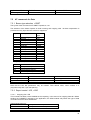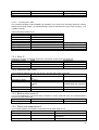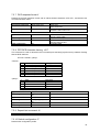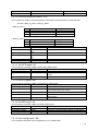
1
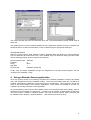
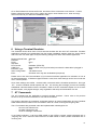
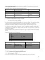
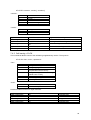
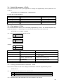
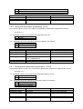
Data & Fax
Functionality
of the
SIEMENS Combiset GSM.
1
2
3
4
5
6
7
Prerequisites and Recommendations .......................................................................................... 4
1.1
Computer HW and SW requirements/recommendations ....................................................... 4
1.2
Telecommunication requirements/recommendations ............................................................ 4
Combiset Installation ................................................................................................................... 5
PC Installation, Setup and Drivers ............................................................................................... 5
3.1
Configuring Windows 95....................................................................................................... 5
Using a Remote Access application............................................................................................. 8
Using an Internet Browser ........................................................................................................... 9
Using a Terminal Emulator ........................................................................................................ 11
AT Commands .......................................................................................................................... 11
7.1
AT commands for Call Control............................................................................................ 12
7.1.1
Dial command D......................................................................................................... 12
7.1.2
Hang-Up command H................................................................................................. 13
7.1.3
Answer a call A .......................................................................................................... 13
7.1.4
Remote disconnection ................................................................................................. 13
7.1.5
DTMF signals +VTD, +VTS ......................................................................................... 13
7.1.6
Operator selection +COPS ......................................................................................... 14
7.1.7
Redial last number ATDL............................................................................................ 14
7.1.8
Signal Quality +CSQ .................................................................................................. 15
7.1.9
Network registration +CREG ....................................................................................... 15
7.1.10 Automatic answer +ATS0 ........................................................................................... 15
7.1.11 Gain control +VGR, +VGT ........................................................................................... 16
7.2
AT commands for SIM, E2prom.......................................................................................... 16
7.2.1
Product Serial Number +CGSN ................................................................................... 16
7.2.2
Request model identification +CGMM.......................................................................... 16
7.2.3
Request revision identification +CGMR........................................................................ 17
7.2.4
Capabilities list +GCAP .............................................................................................. 17
7.2.5
Phone activity status +CPAS ....................................................................................... 17
7.2.6
Power off +CPOF ........................................................................................................ 17
7.2.7
Set phone functionality +CFUN................................................................................... 17
7.2.8
Enter PIN/PUK code +CPIN ....................................................................................... 18
7.2.9
Facility lock +CLCK ..................................................................................................... 19
7.2.10 Change password +CPWD.......................................................................................... 20
7.2.11 Select phonebook memory storage +CPBS ................................................................. 20
7.2.12 Read phonebook entries +CPBR................................................................................. 21
7.2.13 Find phonebook entries +CPBF................................................................................... 21
7.3
AT commands for Short Messages ..................................................................................... 21
7.3.1
Parameters definition................................................................................................... 21
7.3.2
Select message service + CSMS................................................................................. 22
7.3.3
Preferred Message Storage +CPMS............................................................................ 22
7.3.4
Preferred Message Format +CMGF............................................................................. 22
7.3.5
Save settings +CSAS .................................................................................................. 23
7.3.6
Restore settings + CRES............................................................................................. 23
7.3.7
Select TE character set +CSCS................................................................................... 24
7.3.8
New message indication +CNMI.................................................................................. 24
7.3.9
Read Message +CMGR ............................................................................................. 25
7.3.10 List message +CMGL................................................................................................. 26
7.3.11 Send message +CMGS.............................................................................................. 26
7.3.12 Set Text Mode Parameters +CSMP............................................................................. 27
7.3.13 Delete message +CMGD............................................................................................ 27
7.3.14 Service centre address +CSCA .................................................................................. 27
7.3.15 Select Cell Broadcast message +CSCB ..................................................................... 28
7.4
AT Commands for Supplementary Services........................................................................ 28
7.4.1
Call Forwarding +CCFC ............................................................................................. 28
7.4.2
Call barring +CLCK .................................................................................................... 29
7.4.3
Modify SS password +CPWD ..................................................................................... 30
7.4.4
Call waiting +CCWA ................................................................................................... 30
7.4.5
Calling line identification restriction +CLIR .................................................................. 30
7.4.6
Calling line identification presentation +CLIP .............................................................. 31
7.4.7
Connected line identification presentation +COLP ...................................................... 31
7.5
AT commands for Data....................................................................................................... 32
2
7.5.1
Bearer type selection +CBST ..................................................................................... 32
7.5.2
Report control +CR, +CRC ......................................................................................... 32
7.5.3
Echo E ....................................................................................................................... 33
7.5.4
Fixed DTE rate +IPR .................................................................................................. 33
7.5.5
Back to online mode O ............................................................................................... 33
7.5.6
Result code suppression Q.......................................................................................... 33
7.5.7
DCE response format V............................................................................................... 34
7.5.8
DTE-DCE character framing +ICF .............................................................................. 34
7.5.9
Repeat last command A/ ............................................................................................ 34
7.5.10 Default configuration Z ............................................................................................... 34
7.5.11 DTE-DCE local flow control +IFC................................................................................ 35
7.5.12 Set DCD signal &C..................................................................................................... 35
7.5.13 Set DTR signal &D ..................................................................................................... 35
7.5.14 Set DSR signal &S ..................................................................................................... 35
7.5.15 Save configuration &W ............................................................................................... 35
7.5.16 Radio link protocol parameters +CRLP ....................................................................... 36
7.6
Additional AT Commands ................................................................................................... 36
7.6.1
V.25 ter recommendation ............................................................................................ 36
7.6.2
GSM 07.05 recommendation ....................................................................................... 36
7.6.3
GSM 07.07 recommendation ....................................................................................... 36
7.7
Failure result codes ............................................................................................................ 36
7.7.1
Report Mobile Equipment errors +CMEE .................................................................... 36
7.7.2
Extended error report +CEER.................................................................................... 36
7.7.3
ME error result code : +CME ERROR: <error> ............................................................ 37
7.7.4
Message service failure result code: +CMS ERROR : <er>.......................................... 37
7.7.5
Cause information element values from GSM recommendation 04.08.......................... 37
7.7.6
GSM 04.11 Annex E-2: Mobile originating SM-transfer ................................................ 39
7.7.7
Summary of result codes ............................................................................................. 41
3
1 Prerequisites and Recommendations
1.1
Computer HW and SW requirements/recommendations
The underneath PC requirements describes the minimum baseline to be supported.
The
recommendations are not exclusive and does not conclusively imply incompatibility with other HW or
SW platforms.
•
386 PC or higher
Memory, disk space, speed and peripherals as required to run Windows '95 will be sufficient to drive
the Combiset.
•
Serial Communication port
Your PC must be equipped with a physical communication port, supporting RS232 serial data
communication. Typically it is configured as COM1, COM2, COM3 or COM4.
•
Data Cable
A standard serial modem cable is required in order to connect your Combiset and PC for data
application. Refer to Siemens Nixdorf peripherals catalogue [http:///www.siemensnixdorf.com] under
serial modem cables, i.e. Cable KB011-M5, M10 or M15.
9 PIN DB9
female
9 PIN DB9
male
All Pins straight through connected
RS 232 serial cable
PC side
•
Combiset side
Windows 95 or Windows NT
These operating systems are commonly equipped with the data communication drivers and protocols
required to operate the Combiset. Hence no additional installation software is necessary.
•
Data application software
This constitutes end user software which uses data communication as a means of fulfilling a function
i.e. information transfer. These packages typically are 'Email programs, Internet browsers, PC Fax
applications, Remote access applications, File transfer applications, etc. For setup instructions of
individual applications, please refer to the relevant application's accompanying documentation.
1.2 Telecommunication requirements/recommendations
• SIM Card
To operate the Combiset the user requires a valid SIM card from any GSM network operator.
•
TeleServices
A TeleService needs to be enabled on the SIM Card (by the Network Operator) to send/receive faxes
over the GSM network. The Combiset currently supports:
– TeleService 62 (TS62).
•
Data Bearer Services
A Data Bearer Service (BS) needs to be enabled on the SIM Card (by the Network Operator to
send/receive data over the GSM network. The different Data Bearer Services are distinguished
through different rates of data transmission. The Combiset currently supports:
4
–
–
–
•
BS26, (9600 baud, V110 and V32)
BS25, (4800 baud, V32)
BS24, (2400 baud, V110 and V22bis)
PIN Number
The PIN number deserves a prominent discussion due to its likeliness to derail the users attempts to
data connection. Note that this security feature which is inherent to the GSM network, distinguishes
the Combiset from the properties of ordinary fixed-line modems.
Hence the user must contemplate that current data application software will most likely not contain
methods to enter the SIM card PIN number. Three possible ways to address the PIN number:
- Enter the PIN number using the analogue telephone connected to your Combiset. Follow
the instructions as described in the User Manual. This method is recommended as it
maintains the security feature of the SIM card.
Note that once the PIN number is entered it will remain applicable until a new PIN number is
entered or until the Combiset looses power. Hence, if GSM network coverage is lost then
the Combiset will automatically log in without user intervention once network coverage is
again detected. If power is lost however, the user will have to enter the PIN number again
after the power connection is returned.
-
Enter the PIN number over the data interface using a terminal emulator such as Windows
HyperTerminal. Refer to the section on AT commands for instructions. The same PIN
retention rules are observed as in the previous case.
-
Disable the PIN number on the SIM card. In certain cases, mostly emergency services, this
method might be desired. Take note however that it impairs SIM card security and as a
result some Network Operators do not allow PIN disabling. Contact your local Network
Operator in this regard.
2 Combiset Installation
Before attempting to configure the PC, it is necessary to establish that the Combiset is correctly
configured and ready to operate as modem. Please refer to the Combiset User Manual and ensure
that your Combiset, is correctly connected, powered on and logged into the GSM network. Observe
the LED indicators for correct status. Once again remember to disable the PIN number on the SIM
card or enter the PIN number using the connected analogue telephone. Connect the data cable
between the Combiset data port and the PC serial communication port (i.e. COM1) Take note which
port, for the purpose of selecting the corresponding port during PC configuration. The Combiset is
now ready for data communication.
3 PC Installation, Setup and Drivers
To guide you through the PC setup, refer to the relevant paragraph below depending on your
Operating System and your level of expertise.
3.1
Configuring Windows 95
NOVICE USERS:
In the Control Panel 'Start-Settings-Control Panel' under the option 'Modems' the required modem
driver must be installed. Choose 'Add' and in the next window choose 'Other' modem type to be
installed.
5
Indicate in the following window that the modem will be manually selected by clicking the checkbox.
The next installation window lists modem types and models. Within the category 'Standard Modem
Types' Choose 'Standard 9600 bps Modem'. The last window inquires which physical communication
port must be used. Ensure that you select the appropriate COM port corresponding to where the data
cable is plugged in. (i.e. COM1)
Confirm the last window and wait a few seconds for Windows to install the necessary drivers. You will
find yourself back in the original 'Modem Installation Window', and will find the newly added driver
named 'Standard 9600 bps Modem' entered in the list of installed drivers. Select it and choose
'Properties'.
6
Verify once more that the appropriate 'COM port' is selected, as well as that the 'Maximum speed' is
set to 9600 bps. Then choose 'Settings' and insure that the settings are as follows
Data bits:
8
Parity:
None
Stop Bits:
1
Click on the option 'Advanced' and verify that the flow control option is selected and set as follows:
Flow Control:
Hardware (RTS/CTS)
The modem driver for your Combiset is now installed and should be tested/diagnosed. This can be
done once you are back again in the original 'Modem Installation Window' by clicking on the option
'Diagnose/Test'. Under this window option the appropriate 'COM port' with the relevant 'Standard
9600 bps Modem' driver must be selected and then the 'Details' button must be clicked.
7
The modem test will take a few seconds after which the 'Test Results/Details' window should show all
tests 'OK'.
The modem driver is now successfully installed and any application software running on Windows 95,
should be able to do data communication via the Combiset using the appropriate COM port.
ADVANCED USERS:
Within the 'Control Panel' under 'Modems' install a 'Standard 9600 bps Modem' by manual selection
from the Windows 95 modem drivers list. Once installed verify the COM Port setting and also insure
that the following settings under 'Properties' are selected.
Maximum Baud Rate:
Data bits:
Parity:
Stop Bits:
Flow Control:
9600 bps
8
None
1
Hardware (RTS/CTS)
Finally verify successful installation through the 'Diagnose/Test' function located together with the
'modem driver installation ' utility.
4 Using a Remote Access application
Once the previous section is successfully completed the Combiset installation is finished and tested
and it will operate like any other standard modem. From this point forward there are a multitude of
possible combinations of Software, Drivers and Protocol configurations. Hence reference should be
made to the documentation of the specific applications. Here follows an example of at least one
possible way to setup a Remote Access application.
As a prerequisite the user need to have installed a driver for a Remote Access Server (RAS). Refer to
Windows ’95 documentation for instructions. Typically it can be verified or added within the Windows
’95 ‘Control Panel – Software – Windows Setup’. Once this is done the option ‘New Connection’ will
be available under ‘Desktop – Remote Network’ . (also referred to as RAS or DFU).
8
Select ‘New Connection’ and enter a name for the Remote Connection which you are now creating.
(ex. My Service Provider). As driver choose the ‘Standard 9600 bps Modem‘ which you have installed
in the previous section of this document.
In the next window enter the area code and telephone of your target access point (i.e. your service
provider) and confirm. Once the new connection information has been entered it is created as an icon
under ‘Desktop – Remote Network’ with the user defined name (i.e. My Service Provider)
Select the newly created icon (‘My Service Provider’) and enter your username and password to
connect to your remote target. Dial and enjoy remote access via your Siemens COMBISET GSM.
5 Using an Internet Browser
Once the Combiset has been installed (see Section 3) it will operate like a normal modem. To enable
Internet connection a variety of possible combinations of Software, Drivers and Protocol configurations
exists as public as well as proprietary configurations of Service Providers, Network Operators and
Software Companies. Hence reference should be made to these parties for specific application
assistance. Here follows an example of at least one possible way to setup an Internet Browser
application.
It entails creating a ‘Remote Access Connection’ of type ‘PPP’ on TCP/IP network protocol and then
running Netscape Navigator (V4.06) as your Internet browser application over this connection.
9
Refer to Section 4 to create a Remote Access Connection to your Internet Service Provider. Once
completed verify the connection properties by method of ‘right click’ on the newly created icon (‘My
Service Provider’) and choose the option ‘properties’.
Verify the telephone number of your Service Provider and that the Standard 9600 bps Modem (as
installed in Section 3) will be used. Also verify that RAS server is of type PPP for Windows ’95 and
ensure that only TCP/IP is enabled as a network protocol. Confirm these parameters and then
connect to your remote location (service provider) with username and password.
Once the connection is established you can also verify from the ‘Connection Information’ that only
TCP/IP is used. Then start your Internet Browser Application (Netscape Navigator v4.06).
10
Go to ‘Edit-Preferences-Advanced-Proxies’ and select ‘Direct connection to the Internet’. Confirm,
Return to Browser screen and in the ‘Location’ box type in ‘www.siemens.com’, enter and enjoy
Internet access via your Siemens COMBISET GSM.
6 Using a Terminal Emulator
The Combiset can be driven from a from a terminal emulator with the use of AT commands. Emulator
applications normally runs independent from the modem installation settings under the ‘Control Panel’
and hence the user must again verify the following settings from within the emulator application.
Maximum Baud Rate:
Data bits:
Parity:
Stop Bits:
Flow Control:
COM Port:
Emulation Type:
ASCII configuration:
Echo:
9600 bps
8
None
1
Hardware (RTS/CTS)
Must correlate to the physical serial port where the data cable is plugged in.
ANSI
7-bit ASCII format
Character echo may also be disabled (If required)
Please refer to the User Documentation of your terminal emulator application for indication on how to
set these parameters. If Windows HyperTerminal is used, then these settings can be found under the
menu ’File-Properties’.
Once these settings are verified, the data cable connected and the Combiset powered on, then type
‘AT↵’ and the Combiset should respond with ‘OK’. On receiving this message you have successfully
established a terminal session with the Combiset. Refer to the AT commands chapter on how to enter
the PIN number, verify signal strength, verify registration and setup and termination of a call.
7 AT Commands
The AT Command set are applicable to terminal emulator sessions. Hence refer to the previous
section to set up a terminal emulator for use with the Combiset.
This section describes the messages exchanged between an external application and the Combiset
GSM mobile terminal, based on AT commands in order to control incoming and outgoing calls.
The AT-commands are presented under the implementation subcategories for
- the voice call Teleservices,
- the data Teleservices and
- the short message Teleservices.
In the GSM vocabulary, a call from GSM mobile to the PSTN is named „mobile originated call“ or
„outgoing call“, and a call from fixed network to a GSM mobile is called „mobile terminated call“ or
incoming call“.
11
•
Terminal line settings
Currently, the GSM module handler is set to 9600 bps, 8 bits data, 1 bit stop, no parity, RTS/CTS flow
control. Please use the commands +IPR, +IFC, +ICF to change these settings.
•
Command line
Commands always finish with a <CR> character.
•
Information responses and result codes
Responses start and end with <CR> <LF>, except with the ATV0 (DCE response format) and ATQ1
(result code suppression) commands.
-
If the syntax command is wrong, the string ERROR is sent.
If the syntax command is correct but with some incorrect parameters, the string
+CME ERROR: <err> is sent with different error codes.
If the command line has been performed successfully, the string OK is sent.
In some cases like “AT+CPIN?“ or incoming events the module does not finish its response with the
string OK.
In the following examples <CR> and <CR> <LF> will be intentionally omitted.
7.1
AT commands for Call Control
7.1.1 Dial command D
This AT command is used by the external application to establish a call.
For a data call, the application sends to the GSM module the following ASCII string: (the bearer has to
be selected before with the +CBST command).
ATD <nb> where <nb> is the called phone number.
For a voice call, the application sends to the GSM module the following ASCII string: (the bearer may
be selected before, if not a default bearer is used).
ATD <nb>; where <nb> is the called phone number.
The answer to the command is the following:
Verbose result code
OK
CONNECT <speed>
Numeric (V0 set)
0
10, 11, 12, 13, 14, 15
BUSY
NO ANSWER
7
8
Description
If the call succeeds, for voice call only
If the call succeeds, for data call only,
<speed> takes the value negotiated by the
GSM module
If the called party is in communication
If no hang up is detected after a fixed network
time-out
Please, notice that in case of international number, the local international prefix does not need to be
set (usually 00) but need to be replaced by the ‚+‘ character.
Example: to establish a voice call to Siemens from another country, the AT command shall be:
ATD +49897220;
Notice that some country can have particular numbering rules for their GSM handset numbering.
12
Direct dialling from a phonebook location (stored in SIM card) can be done with the following
command:
ATD>17; or
ATD>SIM17;
(voice call here)
ATD>“FRED“;
for calling „FRED“ from the phonebook
7.1.2 Hang-Up command H
This command is used by the application to disconnect the remote user.
The application sends:
Application to GSM
GSM to application
ATH
OK
Ask for disconnection
Even if there is no communication established
7.1.3 Answer a call A
When the GSM module receives a call, it set the Ringlnd signal and sends to the application the
ASCII string RING. Then it waits for the application to accept the call.
Application to GSM
GSM to application
Application to GSM
GSM to application
ATA
OK
ATA
NO CARRIER
normal case
If ATA is sent when no incoming call was
indicated (operation not allowed)
7.1.4 Remote disconnection
This message is used by the GSM module to indicate to the application that the communication has
been released by the remote user.
The GSM module sends „NO CARRIER“ to the application, and set the DCD signal.
7.1.5 DTMF signals +VTD, +VTS
The GSM module offers the user application to send DTMF tones. One command shall be used for
defining the duration of the tones (default value is 70 ms), the other for sending the Tones.
For defining the duration, the application uses:
AT+VTD=<n>
where <n>*100 gives the duration in ms.
Application to GSM
GSM to application
Application to GSM
GSM to application
AT+VTD=1
OK
AT+VTD=100000
+CME ERROR:3
Application to GSM
GSM to application
AT+VTD=0
OK
for defining 100 ms tone duration
command valid
if the duration is too long (the limit is to define for
each application)
For setting the manufacturer default value
For sending DTMF tones, the application uses:
AT+VTD=<Tone>
where <Tone> is in (0-9,*,#,A,B,C,D)
13
Application to GSM
GSM to application
Application to GSM
GSM to application
Application to GSM
GSM to application
AT+VTS=A
OK
AT+VTS=11
+CME ERROR:4
AT+VTS=4
+CME ERROR:3
command valid
if the <Tone> is wrong
If there is no communication
Example: to send the Tone sequence 13#, the application shall send:
AT+TS=1
OK
and then wait for
AT+VTS=3
OK
and then wait for
AT+VTS=#
OK
and then wait for
7.1.6 Operator selection +COPS
To select the operator, two possibilities exist:
1. The mobile enters the manual mode, and then try to find an operator which is indicated by the
application. It finds and registers correctly, then the mobile stays in idle mode.
2. The mobile enters the automatic mode, and then try to find the home operator. If it finds and
registers correctly, then the mobile stays in idle mode; if not, the mobile looks itself automatically for
another network.
To force an attempt to select and register a GSM network operator, the application must send the
following command:
Syntax:
AT+COPS=<mode>, <format>, <oper>
The first parameter indicates either automatic (value 0) or manual (value 1). The second parameter
indicates the format of the third parameter. The only format supported by the GSM module is the
numerical format (value 2). The third parameters is the operator identifier (MCC3 MCC2 MCC1 MNC2
MNC1).
Application to GSM
GSM to application
Application to GSM
GSM to application
Application to GSM
GSM to application
Application to GSM
GSM to application
Applications to GSM
GSM to application
AT+COPS?
+COPS: 0,2,20801
OK
AT+COPS=?
+COPS: (2,20801), (0,20810)
OK
AT+COPS=1,2,20810
+CME ERROR:3
AT+COPS=1,1,20810
+CME ERROR:4
AT+COS=0,2
OK
ask for current plmn
Home PLMN is France telecom
ask for PLMN list
Home PLMN is France Telecom
SFR network has been seen
ask for registration on SFR network
failed
ask for registration on SFR network
wrong parameters
ask for registration on home network
succeeded
7.1.7 Redial last number ATDL
This command is used by the application to redial the last number used in the command ATD if a
previous ATD command was executed.
14
Application to GSM
GSM to application
ATDL
OK +49897220;
Redial last number
Last Call was a speech call command valid
7.1.8 Signal Quality +CSQ
This command shall be used to know the received signal strength indication (<rssi>) and the channel
bit error rate (<ber>) with or without any SIM card inserted.
<rssi>:
0:
1:
2...30 :
31 :
99 :
-113dBm or less
-111 dBm
-109 to –53 dBm
-51dBm or greater
not known or not detectable
0...7
99 :
as RXQUAL values in the table GSM 05.08
not known or not detectable
<ber>:
Application to GSM
GSM to application
AT+CSQ
+CSQ: <rssi>, <ber> OK
<rssi> and <ber> as defined before
7.1.9 Network registration +CREG
This command is used by the application to know the registration status of the mobile.
<mode>
0 : Disable network registration unsolicited result code
1 : Enable network registration code result code +CREG : <stat>
<stat>
0 : not registered, ME is not currently searching a new operator
1 : registered, home network
2 : not registered, ME currently searching a new operator to register to
3 : registration denied
4 : unknown
5 : registered, roaming
Application to GSM
GSM to application
Application to GSM
AT+CREG?
+CREG: <mode>, <stat> OK
AT+CREG=<mode>
GSM to application
OK
as defined before
disable/enable network registration
unsolicited result code
command valid
7.1.10 Automatic answer +ATS0
This S-parameter controls the automatic answering feature of the mobile.
Application to GSM
GSM to application
Application to GSM
GSM to application
Application to GSM
GSM to application
ATS0=2
OK
ATS0?
002
OK
ATS0=0
OK
automatic answer after 2 rings
Current value
always 3 characters with leading zeros
no automatic answer
command valid
15
All others S-parameters (S6, S7, S8 ...) are not implemented.
7.1.11 Gain control +VGR, +VGT
This command shall be used by the application to tune the receive gain of the speaker and transmit
gain of the microphone. The application shall send
AT+VGR=<val>
0 to 15
16 to 31
32 to 47
48 to 63
64 to 79
80 to 95
96 to 111
112 to 127
128 to 143
144 to 159
160 to 175
176 to 191
192 to 207
208 to 223
224 to 239
240 to 255
for the receive gain
+6 dB
+4 dB
+2 dB
0 dB
-2 dB
-4 dB
-6 dB
-8 dB
-10 dB
-12 dB
-14 dB
-16 dB
-18 dB
-20 dB
-22 dB
-24 dB
AT+VGT=<val>
0 to 31
32 to 63
64 to 95
96 to 127
128 to 159
160 to 191
192 to 223
224 to 255
for the transmit gain
+14 dB
+17 dB
+20 dB
+23 dB
+26 dB
+29 dB
+32 dB
+35 dB
16 levels for receive gain are provided and 8 levels for transmit gain.
Application to GSM
GSM to application
Application to GSM
GSM to application
7.2
AT+VGR=25
OK
AT+VGT=45
OK
command valid
command valid
AT commands for SIM, E2prom
7.2.1 Product Serial Number +CGSN
This command allows the user application to know the IMEI of the GSM module. The application
sends:
Application to GSM
GSM to application
Application to GSM
GSM to application
AT+CGSN
135790248939
OK
AT+CGSN
+CME ERROR: 22
request IMEI
IMEI present in E2PROM
request IMEI
IMEI not found in E2PROM
7.2.2 Request model identification +CGMM
This command is used to get the hardware version.
Application to GSM
GSM to application
AT+CGMM
GSM P 900
OK
get hardware version
GSM 900 MHz primary band
16
7.2.3 Request revision identification +CGMR
This command is used to get the software version.
Application to GSM
GSM to application
AT+CGMR
V2.74
OK
get software version
command valid
7.2.4 Capabilities list +GCAP
This command gives the complete capabilities list.
Application to GSM
GSM to application
AT+GCAP
+CGSM +FCLASS
OK
get capabilities list
supports GSM commands and FAX
7.2.5 Phone activity status +CPAS
This command returns the activity status of the mobile.
Application to GSM
GSM to application
AT+CPAS
+CPAS:<pas>
OK
Current activity status
<pas> can have the following values:
0: ready (allow commands from TA/TE)
1: unavailable (does not allow commands)
2: unknown
3: ringing (ringer is active)
4: call in progress
5: asleep (low functionality)
7.2.6 Power off +CPOF
This command stops the GSM software stack and then the hardware layer.
Application to GSM
GSM to application
AT+CPOF
OK
stop GSM stack
command valid
7.2.7 Set phone functionality +CFUN
This command selects the level of functionality in the mobile station.
When the application wants to stop the module for making a power off, or if the application wants to
force the module for executing a IMSI DETACH procedure, then it has to send:
AT+CFUN=0
This command executes a IMSI DETACH and makes a backup of some internal parameters in the
SIM and the EEPROM.
If the mobile is not powered off after this command, it shall received another command to re-start the
whole GSM process.
If the mobile is turned off after this command, then the power on will automatically execute the start of
the whole GSM process.
17
When the application wants to re-start the module (after having done a AT+CFUN=0 command, and
without having cut the power supply), it has to send:
AT+CFUN=1,1
This command starts again all the GSM stack and GSM functionality.
Application to GSM
GSM to application
AT+CFUN?
+CFUN: 1
OK
AT+CFN=0
OK
AT+CFUN=1
OK
AT+CFUN=1,0
OK
AT+CFUN=1,1
OK
Application to GSM
GSM to application
Application to GSM
GSM to application
Application to GSM
GSM to application
Application to GSM
GSM to application
Ask for current functionality
Full functionality
set minimum functionality
command valid
set full functionality
command valid
set full functionality without reset
command valid
set Full functionality with Reset
command valid
7.2.8 Enter PIN/PUK code +CPIN
This command is used to validate the PIN code (CHV1), or to validate the PUK code (UNBLOCK
CHV1) and to define a new PIN code.
The PIN length is between 4 and 8 digits, the PUK length is 8 digits only.
If the user application try to establish a outgoing call before having validated the SIM PIN code
(CHV1), then the GSM module will refuse the „ATD command with a“ +CME ERROR: 11“ (SIM PIN
required).
It’s up to the application to validate the PIN after each reset or power on if the PIN was enabled. The
application shall therefore use the command:
AT+CPIN=<pin>
Application to GSM
GSM to application
Application to GSM
GSM to application
AT+CPIN=1234
OK
AT+CPIN=5678
+CME ERROR:3
enter PIN
PIN code is correct
enter PIN
operation not allowed, PIN
previously entered
After 3 unsuccessful PIN presentations, the PUK will then be required. The PUK validation forces the
user to enter as a second parameter a new PIN code which will be the new PIN code if the PUK
validation succeeds. The application shall therefore use the command:
AT+CPIN=<puk>,<newpin>
Application to GSM
GSM to application
Application to GSM
GSM to application
AT+CPIN=00000000, 1234
+CME ERROR:16
AT+CPIN=12345678, 1234
OK
enter PUK and new PIN
Incorrect PUK
enter PUK and new PIN, 2nd attempt
PUK correct, new PIN stored
To know which code has to be entered (or not), the following interrogation command can be used:
AT+CPIN?
The possible responses are:
+CPIN: READY
No PIN is needed
18
+CPIN:SIM PIN
+CPIN: SIM PUK
+CME ERROR:<err>
PIN is required
PUK is required
SIM failure (13) absent (10) etc.....
The state „SIM PIN“ is entered only when PIN is enabled and required.
Please note that in this case the mobile does not finish its response with the OK string.
The response +CME ERROR: 13 (SIM failure) is returned after 10 unsuccessful PUK presentations.
The SIM card is then out of order and shall be replaced by a new one.
Example: 3 failed PIN validations + 1 successful PUK validation
AT+CPIN?
+CPIN:SIM PIN
AT+CPIN = 1235
+CME ERROR: 16
AT+CPIN=12336
+CME ERROR: 16
AT+CPIN=1237
+CME ERROR: 16
AT+CPIN?
+CPIN:SIM PUK
AT+CPIN=99999999, 5678
OK
AT+CPIN?
+CPIN:READY
7.2.8.1
read the PIN status
the GSM module requires SIM PIN
First attempt to enter a SIM PIN
bad PIN
Second attempt
bad PIN
Third attempt
bad PIN
Read PIN state
The GSM module requires PUK
the PUK is entered, the new PIN shall be PUK
validation is OK. New PIN is 5678
Read PIN state
GSM module is ready
Remark
In the direction Application to GSM, an „h“ character shall be added before the PIN value if ciphering
mode (with DES algorithm) is enabled
Same remark is valid for +CLCK and +CPWD commands.
7.2.9 Facility lock +CLCK
The syntax of this command is: +CLCK= <fac>, <mode> [,<passwd>]
This command shall be used by the application to change a facility status, with the following <fac>
values:
„PS“:
„SC“:
„AO“:
„OI“:
„OX“:
„AI“:
„IR“:
„AB“:
„AG“:
„AC“:
„WNL“:
SIM lock facility with a 8 digits password.
PIN enable (<mode> = 1) / disable (<mode> = 0)
BAOC (Bar All Outgoing Calls)
BOIC (Bar Outgoing International Calls)
BOIC-exHC (Bar Outg. International Calls except to Home Country)
BAIC (Bar All Incoming Calls)
BIC-Roam (Bar Inc. When Roaming outside Home Country)
All Barring services (only with <mode>=0)
All outgoing barring services (only with <mode>=0)
All incoming barring services (only with <mode>=0)
Network lock with a 8 digits password (NCK).
<mode>
0: unlock the facility
1: lock the facility
19
The password length is given with the AT+CPWD = ? command.
Application to GSM
GSM to application
Application to GSM
GSM to application
Application to GSM
GSM to application
Application to GSM
GSM to application
Application to GSM
GSM to application
Application to GSM
GSM to application
AT+CLCK=“SC“, 1, 1234
OK
AT+CLCK?
+CLCK: („PS“, 0), („SC“, 1), („AO“, 0), („OI“,0),
(„OX“,0), „AI“, 0), („IR“, 0), („AB“, 0), („AG“, 0),
(„AC“, 0), („WNL“, 0)
OK
AT+CLCK=“SC“, 0, 5555
+CME ERROR: 16
AT+CPIN=1234
OK
AT+CLCK=?
+CLCK: („PS“, „SC“, „AO“, „OI“, „OX“,„AI“,
„IR“, „AB“, „AG“, „AG“, „AC“, „WNL“)
OK
AT+CLCK=“WNL“, 1, 12345678
OK
enable PIN
PIN was right
Read PIN status
PIN is enabled, all other facilities
are disable
disable PIN
PIN was wrong
Enter PIN
PIN was good
request supported facilities
supported facilities
Activate network lock
Network lock activated
„+CME ERROR:30“ is returned if the network replied with an error case. (No network service).
7.2.10 Change password +CPWD
This command shall be used by the application to change a password (PIN, call barring, NCK...). The
facility values are the same as for +CLCK command.
For the network lock („WNL“), the unlock is forbidden after 10 failed attempts to disable (unlock) the
network lock with an incorrect password.
Application to GSM
GSM to application
Application to GSM
GSM to application
Application to GSM
GSM to application
Application to GSM
GSM to application
Application to GSM
GSM to application
AT+CPWD=?
+CPWD: („PS“, 8), („SC“, 8), („AO“, 4),
(„OI“, 4), („OX“, 4), („AI“, 4), („IR“, 4),
(„AB“, 4), („AG“, 4), („AC“, 4), („WNL“, 8)
OK
AT+CPWD=“SC“, 1234, 5555
OK
AT+CPWD=“SC“, 1234, 5555
+CME ERROR: 16
AT+CPIN=5555
OK
AT+CPWD=2WNL“, 12345678, 00000000
OK
Possible values
PIN must be on 8 digits
maximum
change PIN
PIN i was good
Change PIN
PIN was wrong
Enter PIN
PIN was good
change NCK
NCK changed for net lock
7.2.11 Select phonebook memory storage +CPBS
This command selects phonebook memory storage. The only available phonebook is the SIM
phonebook („SM“)
Application to GSM
GSM to application
Application to GSM
GSM to application
Application to GSM
GSM to application
AT+CPBS=“SM“
OK
AT+CPBS=?
+CPBS: („SM“)
OK
AT+CPBS?
+CPBS: 2SM“, 10, 20
OK
Selected memory is in SIM
SIM phonebook is selected
Possible values
SIM phonebook supported
Status
SIM phonebook selected, 10 used
locations, 20 locations available
20
7.2.12 Read phonebook entries +CPBR
This command returns phonebook entries for a location range from the current phonebook memory
storage selected with +CPBS.
Application to GSM
GSM to application
AT+CPBR=?
+CPBR: (1-50), 20, 10
OK
Application to GSM
GSM to application
AT+CPBR=12, 14
+CPBR:12, „112“, 129, „Emergency“
+CPBR: 13, „+49897220“, 145, Siemens
+CPBR: 14, „08972246389“, 129, Lionel
OK
AT+CPBR=10
+CPBR: 10, „0896290921“, 129, „Rob“
OK
AT+CPBR=52
+CME ERROR: 21
Application to GSM
GSM to application
Application to GSM
GSM to application
Test command
0 locations (from 1 to 50), max.
length of 20 for phone 10
characters max. for the
associated text
Read entries from 12 to 14
Display locations 12, 13, 14
With Location, Number,
Type (TON/NPI), Text
Read entry 10
Display location 10
Read entry 52 (wrong)
Invalid index
7.2.13 Find phonebook entries +CPBF
This command returns phonebook entries which alphanumeric field start with a given string. The
AT+CPBF= ‚‘‘‘‘ command can be used to display all phonebook entries sorted in alphabetical order.
Application to GSM
GSM to application
Application to GSM
GSM to application
Application to GSM
GSM to application
7.3
AT+CPBF= ?
+CPBF: 20, 10
OK
AT+CPBF= „E“
+CPBF: 12, „112“, 129, „Emergency“
+CPBF: 15, „+491290101“, 145, „Eric“
OK
AT+CPBF= „H“
+CME ERROR: 22
Test command
Max length of 20 for phone 10
characters for the text
Read entries with „E“
Display locations with text field
starting with „E“
Read entries with „H“
Entry not found
AT commands for Short Messages
7.3.1 Parameters definition
<da>
Destination address.
<dcs>
Data coding scheme and is coded like in document [5].
<dt>
Discharge time.
<fo>
Coded like first octet of SMS-SUBMIT in document [4].
<index>
Place of storage in memory.
<length>
Number of characters in text mode or the length of data binary string in
PDU mode.
<mr>
Message reference.
21
<oa>
Originator address.
<pid>
Protocol identifier.
<pdu>
Binary string coded as specified in document [4]
<ra>
Recipient address.
<sca>
Address of the service centre.
<scts>
Service centre time stamp.
<st>
Status.
<stat>
Status of message in memory.
<tooa>
Integer format of <oa>.
<tora>
Integer format of <ra>.
<tosca>
Integer format of <sca>.
<vp>
Validity period of the message.
7.3.2 Select message service + CSMS
The supported services are GSM originated and terminated short message services (SMS-PP), and
the cell broadcast service (SMS-CB)
Application to GSM
GSM to application
Application to GSM
GSM to application
AT+CSMS?
+CSMS: 0, 1, 1, 1
OK
AT+CSMS=?
+CSMS: (0)
OK
Current service
GSM 03.40 et 03.41, SMS-MO, SMS-MT and
SMS-CB supported
Possible service
Only GSM 03.40 et 03.41 is possible
7.3.3 Preferred Message Storage +CPMS
The incoming messages are automatically stored in the SIM.
Application to GSM
GSM to application
Application to GSM
GSM to application
AT+CPMS?
+CPMS: „SM“, 3, 10
OK
AT+CPMS=?
+CPMS: „SM“
OK
Read SIM message storage property
3 messages are stored in SIM. 10 is the total
available SIM memory
Possible storage
Only SIM memory storage is possible
7.3.4 Preferred Message Format +CMGF
The formats implemented are the text mode and the PDU mode.
•
In PDU mode, a complete SMS Message including all header information is passed as a binary
string (in hexadecimal format i.e. „0“, „1“, „2“, „3“, „4“, „5“, „6“, „7“, „8“, „9“, „A“, „B“, „C“, „D“, „E“,
„F“). Each pair or characters is converted to a byte (ex: ‘41‘ is converted to the ASCII character
„A“, whose ASCII code is 0x41 or 65).
•
In Text mode, every commands and responses are in ASCII characters.
22
The chosen format is stored in E2PROM by the command +CSAS.
Application to GSM
GSM to application
Application to GSM
GSM to application
AT+CMGF?
+CMGF:1
OK
AT+CMGF=?
+CMGF: (0-1)
OK
current message format
Text mode
Possible message format
Text or PDU modes are available
Example to send a SMS Message in PDU mode
Application to GSM
GSM to application
Application to GSM
GSM to application
AT+CMGF=0
OK
AT+CMGS=14<CR>
01F60691214365000004C9E9340B
+CMGS:246
OK
PDU message format
PDU mode valid
Send complete SM (14 bytes)
in PDU mode
SM is correctly sent
In this example:
14 is the length of octets of the PDU buffer coded as GSM 03.40.
The buffer is:
0x01 0xF6 0x06 0x91 0x21 0x43 0x65 0x00 0x00 0x04 0xC9 0xE9 0x34 0x0B
which means, regarding to GSM 03.40:
TP-MTI:
0x01 (SMS-SUBMIT)
<mr>:
0xF6 (Message Reference)
<da>:
0x06 0x91 0x21 0x43 0x65 (destination add +123456)
<pid>:
0x00 (Protocol Identifier)
<dcs>:
0x00 (Data Coding Scheme: 7 bits alphabet chosen)
TP-UDL:
0x04 (User Data Length)
TP-DU:
0xC9 0xE9 0x34 0x0B (User Data: ISSY)
TPDU in hexadecimal format must be converted into two ASCII characters. For example, hexadecimal
value 0x2A is presented to the mobile as two characters „2“ (ASCII 50) and „A“ (ASCII 65).
7.3.5 Save settings +CSAS
All settings specified in command +CSCA, +CMGF, +CSMP, +CNMI, +CSDH are stored in E2PROM if
the SIM card is phase 1 or in the SIM card if the relevant SIM card is phase 2.
Application to GSM
GSM to application
AT+CSAS
OK
Store
command correct
7.3.6 Restore settings + CRES
All settings specified in command +CSCA, +CMGF, +CSMP, +CNMI, +CSDH are restored from
E2PROM if the SIM card is phase 1 or from the SIM card the SIM card is phase 2.
23
Application to GSM
GSM to application
AT+CRES
OK
Restore
command correct
7.3.7 Select TE character set +CSCS
This commands informs the ME which set is used by the TE. ME is then able to convert character
strings correctly. This is used for commands +CMGS in text mode.
Application to GSM
GSM to application
Application to GSM
GSM to application
AT+CSCS = „GSM“
OK
AT+CSCS = „PCCP437“
OK
GSM default alphabet
Command valid
PC character set Code Page 437
Command valid
7.3.8 New message indication +CNMI
This command selects the procedure how received messages from the network, should be handled.
The application must send the following command:
AT+CNMI = <mode>, <mt>, <bm>, <ds>, <bfr>
<mode>: controls the processing of unsolicited result codes
0
1
2
3
Buffer unsolicited result codes in the TA. If TA result code buffer is full, indications can be
buffered in some other place or the oldest indications may be discarded and replaced with the
new received indications.
Discard indication and reject new received message unsolicited result codes when TA-TE link is
reserved. Otherwise forward them directly to the TE.
Buffer unsolicited result codes in the TA when TA-TE link is reserved and flush them to the TE
after reservation. Otherwise forward them directly to the TE.
Forward unsolicited result codes directly to the TE.
<mt>: sets the result code indication routing for SMS-DELIVER indications
0
1
3
no SMS-DELIVER indications are routed.
SMS-DELIVER indications are routed using unsolicited code:
+CMT: <<SM>>, <index> (location of stored SM in SIM card)
SMS-DELIVER indications (except class 2 messages) are routed using unsolicited code:
+CMMT: <pdu> (PDU mode)
or
+CMT: <oa>, <scts>[, <tooa>, <fo>, <pid>, <dcs>, <sca>, <tosca>, <length] <CR><LF><data>
Class 3 SMS-DELIVER indications are routed directly using code in <mt>=2;
message of other classes result in indication <mt>=1
<bm>: set the rules for storing received CBMs (Cell Broadcast Message) types depend on its coding
scheme, the setting of Select CBM Types (+CSCB command) and <bm>
0
2
no CBM indications are routed to the TE
New CBMs are routed directly to the TE using unsolicited result code.
+CBM: <length><CR><LF><pdu> (PDU mode)
or
+CBM: <sin>, <mid>, <dcs>, <page>, <pages><CR><LF><data> (Text mode)
<ds> for SMS-STATUS-REPORT
0
no SMS-STATUS-REPORT are routed.
24
1
SMS-STATUS-REPORT are routed using unsolicited code:
+CDS: <pdu> (if PDU mode chosen)
or
+CDS: <fo>, <mr>[, <ra>, <tora>], <scts>, <dt>, <st> (text mode)
<bfr<
0
1
TA buffer of unsolicited result codes defined within this command is flushed to the TE when
<mode> 1..3 is entered (OK response shall be given before flushing the codes)
TA buffer of unsolicited result codes defined within this command is cleared when <mode>
1...3 is entered.
Example:
Application to GSM
GSM to application
GSM to application
Application to GSM
GSM to application
GSM to application
Application to GSM
GSM to application
Application to GSM
GSM to application
GSM to application
AT+CNMI=0,1,0,0,0
OK
+CMTI : « SM », 1
AT+CNMI=0,2,0,0,0
OK
+CMT :"123456","13/01/99
12h30m00s",129,4,32,240,"15379",129,5<C
R><LF>
HELLO
AT+CNMI=0,0,0,1,0
OK
AT+CMGS="+491718657812"<CR>
Hello, how are you ?^Z
+CMGS : 116
OK
+CDS : 2,116, "+491718657812",145,
"13/01/99 12h30m00s","14/01/99
20h51m05s",16
<mt>=1
Message received
<mt>=2
Message received
<ds>=1
Send a message in text mode
Successful transmission
7.3.9 Read Message +CMGR
The Read Message command allows the application to read incoming stored messages.
AT+CMGR=<index>
+CMGR=<stat>,<oa><scts>[,<tooa>,<fo>,<pid>,<dcs>,<sca>,<tosca>,<length>]
<CR><LF><data> (for SMS deliver only)
This command is also available in PDU mode.
+CMGR=<stat>,<length<CR><LF><pdu>
Example :
GSM to application
Application to GSM
GSM to application
Application to GSM
GSM to application
+CMTI: "SM",1
AT+CMGR=1
+CMGR: "REC UNREAD",
"49892449"<CR>
To be or not to be!
OK
AT+CMGR=1
+CMGR: "REC READ",
"49892449",20<CR>
To be or not to be!
OK
New message received
read the message
read again the message
25
Application to GSM
GSM to application
Application to GSM
GSM to application
AT+CMGR=2
+CMS ERROR: 321
AT+CMGR=1
+CMGR: "REC READ",
<length><CR><LF><pdu>
OK
read + bad index
error : invalid index
in PDU mode
7.3.10 List message +CMGL
This command allows the application to read stored messages, by indicating the type of the message
to read.
AT+CMGL=<stat>
<stat> (status of message in memory) :
0
"REC UNREAD" ( received unread message )
1
"REC READ"( received read message )
2
"STO UNSENT"( stored unsent message )
3
"STO SENT"( stored sent message )
4
"ALL"( all messages )
The use of “ALL” instead of 4 is also possible for <stat>
+CMGL=<index>,<stat>,<da/oa>[,<alpha>,<scts>,<tooa/toda>,<length>]<CR><LF><data>
This command is also available in PDU mode.
+CMGL=<index>,<stat>,<length<CR><LF><pdu>
Example :
Application to GSM
AT+CMGL=0
GSM to application
+CMGL: 1, "REC UNREAD",
"49892449"<CR>
To be or not to be!
+CMGL: 3, "REC UNREAD",
"49890800"<CR>
Happy Birthday!
OK
AT+CMGL=1
Application to GSM
GSM to application
Application to GSM
GSM to application
+CMGL: 2, "REC READ",
"49892449",20<CR>
Remember the keys
OK
AT+CMGL=2
+CMS ERROR: 321
read all messages of status
REC UNREAD
read all messages of status
REC READ
read + bad index
error : invalid index
7.3.11 Send message +CMGS
The <address> field is the address of the terminal to whom the message is sent . To send the
message, simply type the <ctrl-Z> character (ASCII 26). The text may contain all existing characters
except <ctrl-Z> and <Esc> (ASCII 27)
Example:
Application to GSM
AT+CMGS="+491718657812"<CR>
Send a message in text mode
26
GSM to application
Application to GSM
GSM to application
Hello, how are you ?<ctrl-Z>
+CMGS : <mr>
OK
AT+CMGS=<length><CR>
<pdu><ctrl-Z>
+CMGS : <mr>
OK
Successful transmission
Send a message in PDU
mode
Successful transmission
The message reference <mr> which is returned back to the application is allocated by the GSM
module. This number begins with 0 and is incremented by one for each outgoing message
(successful and failure case) ; it is cyclic on one byte (0 follows 255).
Note : this number is not a storage number - outgoing messages are not stored.
7.3.12 Set Text Mode Parameters +CSMP
This command shall be used to select value for the <fo>, <vp>, <pid> and <dcs> SMS parameters in
text mode. The application must send the following command:
AT+CSMP= <fo>, <vp>, <pid>, <dcs>
In text mode <vp> is only coded in “relative” format. The default value is 167 (24 hours). This means
that one octet can describe different values.
<pid> is used to indicate the higher layer protocol being used or indicates interworking with a certain
type of telematic device. For example, 0x22 is for group 3 telefax, 0x24 is for voice telephony and
0x25 is for ERMES.
<dcs> is used to determine the way the information is encoded. UCS2 alphabet and compressed text
are supported.
Application to GSM
GSM to application
AT+CSMP?
+CSMP: 0,0,0,0
Application to GSM
AT+CSMP=16,20,64,244
GSM to application
OK
Current values
No valid period
<dcs>=PCCP437 alphabet (8 bit -> 7)
<vp>=20 hours (2 hours, relative format)
<dcs>= GSM 8 bits alphabet
Command correct
7.3.13 Delete message +CMGD
This command shall be used after a read-command in order to delete the received stored message.
For example :
GSM to application
Application to GSM
GSM to application
Application to GSM
GSM to application
+CMTI: "SM",3
AT+CMGR=3
+CMGR: "REC UNREAD",
"49892449",20<CR>
To be or not to be!
OK
AT+CMGD=3
OK
New message received
Read it
Delete message number 3
7.3.14 Service centre address +CSCA
This command shall be used to indicate to which service centre the message has to be sent.
The GSM module has no default value for this address. If the application tries to send a message
without having indicated the service centre address, an error will be generated.
27
Hence, the application has to indicate this address at initialisation. This address then remains valid
until changed by the application.
For example, suppose that no AT+CSCA has been already sent.
Application to GSM
AT+CMGS="+491712657812"<CR>
Hello, how are you ?^Z
GSM to Application
+CMS ERROR : 330
Application to GSM
AT+CSCA="96741234"
GSM to application
OK
Application to GSM
AT+CMGS="+491712657812"<CR>
Hello, how are you ?^Z
GSM to application :
+CMGS : 1
OK
Send a message
Service centre unknown
Service centre initialisation
Send again the same
message
Successful transmission
7.3.15 Select Cell Broadcast message +CSCB
AT+CSCB=<mode>,[<mids>,[<dcss>]]
The command selects which types of CBMs are to be received by the ME. The command is allowed
in PDU mode only (AT+CMGF=0) with <bm>=2 in AT+CNMI command (ex: AT+CNMI=2,2,2)
Interrogation command (AT+CSCB?) returns supported <mode> values as a compound value.
The activation of CBM reception (<mode>=0) can select only specific message identifiers (list in
<mids>) for specific languages (list in <dcss>), but the deactivation stops any reception of CBMs.(only
AT+CSCB=1) is allowed.
Message identifiers (<mids>) parameter indicates which type of message identifiers the ME should
listen to.
Supported languages (<dcss>) parameter is:
0
1
2
3
4
5
6
7
German
English
Italian
French
Spanish
Dutch
Swedish
Danish
8
9
10
11
12
13
14
32
Portuguese
Finnish
Norwegian
Greek
Turkish
Hungarian
Polish
Czech
Application to GSM
AT+CSCB=0,"15-17,50,86",””
GSM to Application
GSM to Application
OK
+CBM: 10<CR><LF>
0011223345566778899
AT+CSCB=1
OK
Application to GSM
GSM to application
7.4
Accept SMS-CB types 15, 16, 17, 50 and
86 in any language
CBMs can be received
CBM length of a received CB message
CBM bytes in PDU
Deactivate the reception of CBMs
CBM reception is completely stopped
AT Commands for Supplementary Services
7.4.1 Call Forwarding +CCFC
This commands allows control of the call forwarding supplementary service. The syntax is :
28
AT+CCFC=<reason>,<mode>[, <number>]
<reason> :
0
1
2
3
4
5
unconditional
mobile busy
no reply
not reachable
all call forwarding
all conditional call forwarding
2
3
4
interrogate
registration
erasure
<mode> :
Application to GSM
GSM to application
Application to GSM
GSM to application
Application to GSM
GSM to application
AT+CCFC=0,3,49897220
OK
AT+CCFC=0,2
+CCFC=1,7,49897220
OK
AT+CCFC=0,4
OK
register call forwarding unconditional
command valid
interrogate call forwarding unconditional
call forwarding active
erase call forwarding unconditional
command valid
7.4.2 Call barring +CLCK
This commands allows control of the call barring supplementary service. The syntax is :
AT+CLCK=<fac>,<lock>, <password>
<fac> :
AO
AI
OI
OX
AG
AC
AB
barring all outgoing calls
barring all incoming calls
barring outgoing international calls
barring outgoing international calls
except those to home country
barring incoming calls when roaming
outside home country
all outgoing barring services
all incoming barring services
all barring services
0
1
unlocks the facility
locks the facility
IR
<lock>:
Password code must be on 4 digits maximum.
Application to GSM
GSM to application
Application to GSM
GSM to application
Application to GSM
GSM to application
AT+CLCK="AO",1,1234
OK
AT+CLCK="AO",0,5555
+CME ERROR: 16
AT+CLCK="AO",0,1234
OK
command valid
wrong password
command valid
29
7.4.3 Modify SS password +CPWD
This command shall be used by the application to change the supplementary service password. The
syntax is:
AT+CPWD=<fac>,<oldpassword>, <newpassword>
for <fac> see +CLCK command.
Application to GSM
GSM to application
Application to GSM
GSM to application
Application to GSM
GSM to application
AT+CPWD="AO",1234,5555
OK
AT+CPWD="AO",1234,5555
+CME ERROR: 16
AT+CPWD="AO",5555,1234
OK
change password
Password was good
Change password
password wrong
change password
Password was valid
7.4.4 Call waiting +CCWA
This command allows control of the call waiting supplementary service. The terminal supports only
single call activities. If call waiting occurs, the terminal will disconnect the second call.
AT+CCWA=<n>,<mode>[, <class>]
<n> : (result code presentation status in the TA)
0
Disable
1
Enable
<mode> :
0
1
2
Disable
Registration
Interrogate
0
1
2
Voice
Data
Fax
<class> :
Application to GSM
GSM to application
Application to GSM
GSM to application
GSM to application
Application to GSM
GSM to application
AT+CCWA=1,1
OK
AT+CCWA=1,2
+CCWA="x",7
OK
RING
+CCWA: +49897220,145,7
NO CARRIER
AT+CCWA=1,0
OK
enable call waiting
command valid
interrogate call waiting
"x" = 1 active
"x" = 0 not active
incoming call
number of the incoming call
incoming call is disconnected
erase call waiting
command valid
7.4.5 Calling line identification restriction +CLIR
This command allows control of the calling line identification restriction supplementary service:
AT+CLIR=<n>
<n> : parameter sets the adjustment for outgoing calls
0
set presentation indicator according to the subscription of the CLIR service
1
CLIR invocation
2
CLIR suppression
<m> : parameter shows the subscriber CLIR service status in the network
30
0
1
2
CLIR not provisioned
CLIR provisioned
Unknown (no network)
Application to GSM
GSM to application
Application to GSM
GSM to application
AT+CLIR=2
OK
AT+CLIR?
+CLIR: <n>,<m>
OK
command valid
Ask for current functionality
"n" and “m” as defined above
7.4.6 Calling line identification presentation +CLIP
This command allows control of the calling line identification presentation supplementary service :
AT+CLIP=<n>
<n> : parameter sets/shows the result code presentation in the TA
0
Disable
1
Enable
<m> : parameter shows the subscriber CLIR service status in the network
0
CLIP not provisioned
1
CLIP provisioned
2
Unknown (no network)
Application to GSM
GSM to application
Application to GSM
GSM to application
GSM to application
Application to GSM
GSM to application
AT+CLIP=1
OK
AT+CLIP?
+CLIP: <n>,<m>
OK
RING
+CLIP: +49897220,145
AT+CLIP=0
OK
Enable CLIP
CLIP is enabled
ask for current functionality
"n" and “m” as defined above
incoming call
Disable CLIP
Command valid
7.4.7 Connected line identification presentation +COLP
This command allows control of the connected line identification presentation supplementary service:
AT+COLP=<n>
<n> : parameter sets/shows the result code presentation status in the TA
0
Disable
1
Enable
<m> : parameter shows the subscriber COLP service status in the network
0
COLP not provisioned
1
COLP provisioned
2
Unknown (no network)
Application to GSM
GSM to application
Application to GSM
GSM to application
Application to GSM
GSM to application
AT+COLP=1
OK
AT+COLP?
+COLP: 1,<m>
OK
ATD+49897220;
+COLP: +49897220,145
OK
Activate COLP
command valid
ask for current functionality
<m> as defined above
outgoing call
31
Application to GSM
GSM to application
7.5
AT+COLP=0
OK
Deactivate COLP
command valid
AT commands for Data
7.5.1 Bearer type selection +CBST
The syntax of the command is AT+CBST=<speed>,0,<ce>
The selection of the bearer impacts on both incoming and outgoing calls. No data compression is
provided and only asynchronous modem is supported.
<speed>
Description
0
1
2
3
4
5
6
7
8
65(*)
66(*)
68
70
71
autobauding
300 bps
1200 bps
1200/75 bps
2400 bps
2400 bps
4800 bps
9600 bps
Specific
300 bps
1200 bps
2400 bps
4800 bps
9600 bps
Modem
type
None
V.21
V.22
V.23
V22bis
V26ter
V32
V32
V110
V110
V110
V110
V110
(*) Only for transparent mode
<ce>
0
1
100
101
Connection element
Transparent only
Non transparent only
Transparent preferred
Non transparent preferred
Application to GSM
GSM to application
Application to GSM
GSM to application
AT+CBST=7,0,1;
OK
AT+CBST=81,0,0
+CME ERROR: 4
Ask for a bearer
Bearer supported
Ask for a bearer
Bearer nor supported
Note that the two last parameters may be omitted. Their default value, when omitted, is 0
(asynchronous) and 1 (non transparent).
7.5.2 Report control +CR, +CRC
7.5.2.1 Outgoing Call +CR
This command enables a more detailed service reporting, in the event of an outgoing data call. Before
sending the CONNECT response to the application, the GSM module will precise the type of data
connection that have been established.
These report types are :
+CR: ASYNC
+CR: REL ASYNC
Application to GSM
for asynchronous transparent
for asynchronous non-transparent
AT+CR=0
extended reports disabled
32
GSM to application
OK
Application to GSM
AT+CR=1
GSM to application
OK
The Default value is stored in E2PROM.
command valid
extended reports enabled
Command valid
7.5.2.2 Incoming Call +CRC
This command enables a more detailed ring indication, in the event of an incoming call (voice or data).
Instead of the string "RING", an extended string is used to indicate which type of call is ringing. (e.g.
+CRING: VOICE)
These extended indications are :
+CRING: ASYNC
for asynchronous transparent
+CRING: REL ASYNC
for asynchronous non-transparent
+CRING: VOICE
for normal speech.
+CRING: FAX
for fax calls.
Application to GSM
AT+CRC=0
GSM to application
OK
Application to GSM
AT+CRC=1
GSM to application
OK
Default value is stored in E2PROM.
extended reports disabled
command valid
extended reports enabled
command valid
7.5.3 Echo E
Determines whether the terminal echoes the commands received over the serial port..
Application to GSM
ATE0
no local echo
GSM to application
OK
command valid
Application to GSM
ATE1
local echo
GSM to application
OK
command valid
7.5.4 Fixed DTE rate +IPR
This commands specifies the data rate at which the DCE will accept commands.
Application to GSM
AT+IPR?
GSM to application
+IPR: 9600
current rate is 9600 bps
OK
Application to GSM
AT+IPR=?
possible values. No
GSM to application
+IPR: (),(2400,9600,19200,38400,57600,
autodetectable rate supported
115200)
OK
Application to GSM
AT+IPR=38400
GSM to application
OK
new rate is 38400 bps
7.5.5 Back to online mode O
If you have established a connection and the mobile is in online command mode, this command allows
to return to online data mode.
Application to GSM
ATO
GSM to application
OK
command valid
7.5.6 Result code suppression Q
This command determines whether the terminal sends result codes or not.
Application to GSM
ATQ0
DCE transmits result codes
GSM to application
OK
Command valid
Application to GSM
ATQ1
Result codes are suppressed and not
transmitted
GSM to application
(none)
No response
33
7.5.7 DCE response format V
Determines the DCE response format, with or without header characters <CR><LF>, and with the use
of numerical result codes.
Information Responses
V0
<text><CR><LF>
Result Codes
<numeric code><CR>
Application to GSM
ATV0
GSM to application
Application to GSM
0
ATV1
GSM to application
OK
V1
<CR><LF>
<text><CR><LF>
<CR><LF>
<verbose code><CR><LF>
DCE transmits limited headers and trailers and
numeric result codes
Command valid (0 means OK)
DCE transmits full headers and trailers and
verbose response text
Command valid
7.5.8 DTE-DCE character framing +ICF
This command is used to determine the local serial port start-stop (asynchronous) character framing
that the DCE shall use.
AT+ICF=<format>,<parity>
<format> :
0
1
2
3
4
5
6
autodetect
8 Data 2 Stop
8 Data 1 Parity 1 Stop
8 Data 1 Stop
7 Data 2 Stop
7 Data 1 Parity 1 Stop
7 Data 1 Stop
not supported
supported
supported
supported
supported
supported
supported
0
1
2
3
4
Odd
Even
Mark
Space
None
supported
supported
supported
supported
supported
<parity> :
Application to GSM
GSM to application
Application to GSM
GSM to application
Application to GSM
GSM to application
AT+ICF?
+ICF: 3,4
OK
AT+ICF=?
+ICF: (1-6),(0-4)
OK
AT+ICF=0,0
OK
current values
possible values.
new values
7.5.9 Repeat last command A/
Application to GSM
A/
repeat last command
7.5.10 Default configuration Z
Restores the configuration profile.
34
Application to GSM
GSM to application
ATZ
OK
command valid
7.5.11 DTE-DCE local flow control +IFC
This command is used to control the operation of local flow control between the DTE and DCE.
AT+IFC=<DCE_by_DTE>,<DTE_by_DCE>
< DCE_by_DTE > :
0
1
2
3
None
Xon/Xoff local circuit 103
RTS
Xon/Xoff global on circuit 103
not supported
not supported
supported
not supported
< DTE_by_DCE > :
0
1
2
None
Xon/Xoff circuit 104
CTS
not supported
not supported
supported
Application to GSM
GSM to application
Application to GSM
GSM to application
Application to GSM
GSM to application
AT+IFC?
+IFC: 2,2
OK
AT+IFC=?
+IFC: 2,2
OK
AT+IFC=0,0
OK
current values
possible values.
new values
7.5.12 Set DCD signal &C
This commands controls the Data Carrier Detect (DCD) signal.
Application to GSM
AT&C0
DCD always on
GSM to application
OK
command valid
Application to GSM
AT&C1
DCD matches state of the remote modem's data
carrier
GSM to application
OK
command valid
7.5.13 Set DTR signal &D
This commands controls the Data Terminal Ready (DTR) signal.
Application to GSM
AT&D0
the DTR signal is ignored
GSM to application
OK
command valid
Application to GSM
AT&D1
Modem switches from data to command mode when
DTR switches from ON to OFF
GSM to application
OK
command valid
Application to GSM
AT&D2
Upon DTR switch from ON to OFF, the call is
cleared down
GSM to application
OK
command valid
7.5.14 Set DSR signal &S
This commands controls the Data Set Ready (DSR) signal.
Application to GSM
AT&S0
DSR always on
GSM to application
OK
command valid
Application to GSM
AT&S1
DSR off in command mode, DSR on in data mode
GSM to application
OK
command valid
7.5.15 Save configuration &W
This commands writes the active configuration to non volatile RAM.
35
Application to GSM
GSM to application
AT&W
OK
writes current configuration to E2prom
command valid
7.5.16 Radio link protocol parameters +CRLP
This command allows to change the radio link protocol parameters used for non transparent data
transmission.
AT+CRLP=<up-window size>,<down-window size>,<acknowledgement timer>,
<retransmission attempts>,<reset allowed>
Application to GSM
GSM to application
Application to GSM
GSM to application
7.6
AT+CRLP=10,10,90,10,0
OK
AT+CRLP?
AT+CRLP: 10,10,90,10
OK
set new parameters
command valid
current values
command valid
Additional AT Commands
7.6.1 V.25 ter recommendation
Other remaining basic commands are not implemented, and an “ERROR” string will be returned.
All commands about modulation control, error control and data compression are not recognised. An
"ERROR" string will be returned.
7.6.2 GSM 07.05 recommendation
All remaining commands are not implemented and an “ERROR” string will be returned.
7.6.3 GSM 07.07 recommendation
All remaining commands are not implemented and an “ERROR” string will be returned.
7.7
Failure result codes
7.7.1 Report Mobile Equipment errors +CMEE
This command disables or enables the use of result code on “ERROR” reports:
+CME ERROR : <xxx> or +CMS ERROR :<xxx>
Application to GSM
AT+CMEE=0
GSM to application
OK
Application to GSM
AT+CMEE=1
GSM to application
OK
<xxx> error result codes follow below.
disable « +CME ERROR : <xxx> »
and use « ERROR » instead
enable « +CME ERROR : <xxx> »
7.7.2 Extended error report +CEER
If the last call setup (originating or answering) fails, this command will report the reason of the call
release.
Application to GSM
GSM to application
ATD123456789;
NO CARRIER
outgoing voice call
36
Application to GSM
GSM to application
AT+CEER
+CEER : Error <xxx>
OK
ask for reason of release
<xxx> is the cause information
element values from GSM
recommendation 04.08
The cause information element from GSM 04.08 is given below.
7.7.3 ME error result code : +CME ERROR: <error>
<error> is defined as below :
0
3
4
10
11
12
13
16
17
18
20
21
22
24
26
30
256
257
258
Phone failure
Operation not allowed
Operation not supported
SIM not inserted
SIM PIN required
SIM PUK required
SIM failure
Incorrect password
SIM PIN2 required
SIM PUK2 required
Memory full
Invalid index
Not found
Text string too long
Dial string too long
No network service
Protocol stack : bad state
Bad cell ( not synchronised)
Lost cell ( due to DSF...)
7.7.4 Message service failure result code: +CMS ERROR : <er>
<er> is defined as below :
1 to 127
301
302
303
305
313
321
322
330
512
513
514
error cause values from the GSM
recommendation 04.11 Annex E-2
SMS service of ME reserved
operation not allowed
operation not supported
invalid text mode parameter
SIM failure
Invalid memory index
SIM memory full
SC address unknown
MM establishment failure
Lower layer failure
CP error
7.7.5 Cause information element values from GSM recommendation 04.08
Cause value
1
3
6
8
16
17
Diagnostic
Unassigned (unallocated) number
No route to destination
Channel unacceptable
Operator determined barring
Normal call clearing
User busy
37
18
19
21
22
26
27
28
29
30
31
34
38
41
42
43
44
47
49
50
55
57
58
63
65
68
69
70
79
81
87
88
91
95
96
97
98
99
100
101
102
111
127
252
253
254
255
No user responding
User alerting, no answer
Call rejected
Number changed
Non selected user clearing
Destination out of order
Invalid number format (incomplete number)
Facility rejected
Response to STATUS ENQUIRY
Normal, unspecified
No circuit/channel available
Network out of order
Temporary failure
Switching equipment congestion
Access information discarded
requested circuit/channel not available
Resources unavailable, unspecified
Quality of service unavailable
Requested facility not subscribed
Incoming calls barred with in the CUG
Bearer capability not authorised
Bearer capability not presently available
Service or option not available, unspecified
Bearer service not implemented
ACM equal to or greater than ACMmax
Requested facility not implemented
Only restricted digital information bearer capability is available
Service or option not implemented, unspecified
Invalid transaction identifier value
User not member of CUG
Incompatible destination
Invalid transit network selection
Semantically incorrect message
Invalid mandatory information
Message type non-existent or not implemented
Message type not compatible with protocol state
Information element non-existent or not implemented
Conditional IE error
Message not compatible with protocol state
Recovery on expired timer
Protocol error, unspecified
Interworking, unspecified
Call barring on outgoing calls
Call barring on incoming calls
Call impossible
Lower layer failure
All other values in the range 0 to 31 shall be treated as cause 31.
All other values in the range 32 to 47 shall be treated as cause 47.
All other values in the range 48 to 63 shall be treated as cause 63.
All other values in the range 64 to 79 shall be treated as cause 79.
All other values in the range 80 to 95 shall be treated as cause 95.
All other values in the range 96 to 111 shall be treated as cause 111.
All other values in the range 112 to 127 shall be treated as cause 127.
38
7.7.6 GSM 04.11 Annex E-2: Mobile originating SM-transfer
Cause no 1: "Unassigned (unallocated) number"
This cause indicates that the destination requested by the Mobile Station cannot be reached because,
although the number is in a valid format, it is not currently assigned (allocated).
Cause no 8: "Operator determined barring"
This cause indicates that the MS has tried to send a mobile originating short message when the MS's
network operator or service provider has forbidden such transactions.
Cause no 10: "Call barred"
This cause indicates that the outgoing call barred service applies to the short message service for the
called destination.
Cause no 21: "Short message transfer rejected"
This cause indicates that the equipment sending this cause does not wish to accept this short
message, although it could have accepted the short message since the equipment sending this cause
is neither busy nor incompatible.
Cause no 27: "Destination out of service"
This cause indicates that the destination indicated by the Mobile Station cannot be reached because
the interface to the destination is not functioning correctly. The term "not functioning correctly"
indicates that a signalling message was unable to be delivered to the remote user; e.g., a physical
layer or data link layer failure at the remote user, user equipment off-line, etc.
Cause no 28: "Unidentified subscriber"
This cause indicates that the subscriber is not registered in the PLMN (i.e. IMSI not known)
Cause no 29: "Facility rejected"
This cause indicates that the facility requested by the Mobile Station is not supported by the PLMN.
Cause no 30: "Unknown subscriber"
This cause indicates that the subscriber is not registered in the HLR (i.e. IMSI or directory
number is not allocated to a subscriber).
Cause no 38: "Network out of order"
This cause indicates that the network is not functioning correctly and that the condition is
likely to last a relatively long period of time; e.g., immediately re-attempting the short
message transfer is not likely to be successful.
Cause no 41: "Temporary failure"
This cause indicates that the network is not functioning correctly and that the condition is not
likely to last a long period of time; e.g., the Mobile Station may wish to try another short
message transfer attempt almost immediately.
Cause no 42: "Congestion"
This cause indicates that the short message service cannot be serviced because of high
traffic.
39
Cause no 47: "Resources unavailable, unspecified"
This cause is used to report a resource unavailable event only when no other cause applies.
Cause no 69: "Requested facility not implemented"
This cause indicates that the network is unable to provide the requested short message
service.
Cause no 81: "Invalid short message transfer reference value"
This cause indicates that the equipment sending this cause has received a message with a
short message reference which is not currently in use on the MS-network interface.
Cause no 95: "Invalid message, unspecified"
This cause is used to report an invalid message event only when no other cause in the
invalid message class applies.
Cause no 96: "Invalid mandatory information"
This cause indicates that the equipment sending this cause has received a message where a
mandatory information element is missing and/or has a content error (the two cases are
indistinguishable).
Cause no 97: "Message type non-existent or not implemented"
This cause indicates that the equipment sending this cause has received a message with a message
type it does not recognise either because this is a message not defined or defined but not
implemented by the equipment sending this cause.
Cause no 98: "Message not compatible with short message protocol state"
This cause indicates that the equipment sending this cause has received a message such that the
procedures do not indicate that this is a permissible message to receive while in the short message
transfer state.
Cause no 99: "Information element non-existent or not implemented"
This cause indicates that the equipment sending this cause has received a message which includes
information elements not recognised because the information element identifier is not defined or it is
defined but not implemented by the equipment sending the cause. However, the information element
is not required to be present in the message in order for the equipment sending the cause to process
the message.
Cause no 111: "Protocol error, unspecified"
This cause is used to report a protocol error event only when no other cause applies.
Cause no 127: "Interworking, unspecified"
This cause indicates that there has been interworking with a network which does not provide causes
for actions it takes; thus, the precise cause for a message which is being send cannot be ascertained.
40
7.7.7 Summary of result codes
Verbose result code
+CCCM : <ccm>
+CCWA : <nb>,<type>,<class>
+CLIP : <number>,<type>
+COLP :<number>,<type>
+CR : <type>
+CREG : <stat>
+CRING : <type>
BUSY
CONNECT 300
CONNECT 1200
CONNECT 1200/75
CONNECT 2400
CONNECT 4800
CONNECT 9600
ERROR
NO ANSWER
NO CARRIER
OK
RING
Numeric
(V0 set)
as verbose
as verbose
as verbose
as verbose
as verbose
as verbose
as verbose
7
10
11
12
13
14
15
4
8
3
0
2
Description
Current Call Meter value
Call Waiting number
Incoming Call Presentation
Outgoing Call Presentation
Outgoing Call report control
Network registration indication
Incoming call (VOICE, FAX …)
Busy signal detected
Data connection at 300 baud
Data connection at 1200 baud
Data connection at 1200/75 baud
Data connection at 2400 baud
Data connection at 4800 baud
Data connection at 9600 baud
Command not accepted
Connection completion time-out
Connection terminated
Acknowledges execution of a command line
Incoming call signal from network
41