1
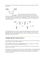
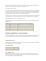
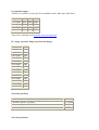
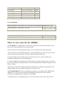
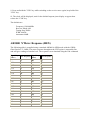
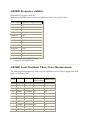
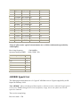
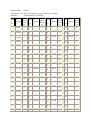
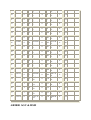
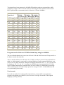
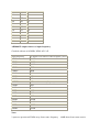
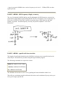
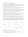
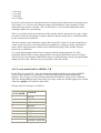
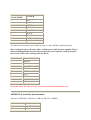
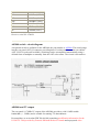
AR5000 Bulletin Page
AR5000 brief production history
The AR5000 first appeared in 1996, the serial numbers were 5xxxx (six digit numbers starting
with the number five). In the first few months of production, some beefing up of the internal
power PCB took place, a trimmer was added to the SSB insertion oscillator (PCB) and some
noise reducing changes added (DDS decoupling, change of RS232 device).
A revision to operation (firmware) appeared after about one year, the serial numbers changed
to 07xxxx (six digit numbers starting zero seven with four digits following).
A board change occurred around serial number 070661 when the AR5000+3 additions
appeared (Synchronous AM, noise blanker, AFC). If the serial number is lower than 070661
we cannot retrospectively add the +3 options:
Around 070661 the EEPROM switching was revised so that an alternate bank of memories
and search banks could be switched (doubling the memory capability).
Minor firmware revisions have taken place since, mainly to boost the durability of EEPROM
when under computer control (commercial operators).
The AR5000C is a frequency coherent version of the AR5000, designed for commercial
operators.
Current serial numbers (February 2003) are around 077xxx.
Retrospective and free updates are NOT available. The AR5000 has been designed &
manufactured by AOR Japan who are officially responsible for international distribution and
support... comment presented here may not reflect their official status or views, AOR UK
LTD.
AR5000 1kHz filter modification
We have had several enquiries regarding the fitting of a 1kHz data filter to the AR5000; in
particular the CFJ455K8 which we originally sourced for our AR7030 HF receiver. The main
problem in fitting this filter to the AR5000 is the physical incompatibility; we have found
however that by turning the filter upside down you can attach short leads to it and connect it
in the MF1 Collins 500Hz filter position on the AR5000 IF board without any great difficulty.
The diagram below shows the CFJ455K8 filter connection details. All three earth connections
should be connected together using tinned copper wire and then soldered to the original
Collins earth connection using thick tinned copper wire to achieve a good physical stability on
the board. Short lengths of wire can now be used to make the in/out connections between the
filter and PCB. If you require a more permanent fixing of the filter to the board we suggest
double sided tape to hold the filter in an upside down position before making the soldered
connections.
Careful examination of the PCB around the filter
connections will show that there are two 33pF SMD
capacitors connected between the filter in/out and earth. Ideally these could be removed to
give a flatter frequency response along with changing R173 to 1k8. In practice however you
will probably not notice any change and we recommend that they are left as standard. The
circuit is shown below
After fitting the filter, refer to page 68 and 69 of the AR5000 instruction manual in order to
register the new filter. You must register the new filter as a 500Hz filter - this is also the
bandwidth that will be displayed when the filter is selected. Unfortunately there is no 1kHz
bandwidth available on the display.
AR5000 DETECTOR OUTPUT
The AR5000 is capable of running various decoders from its ACC1 socket on the front panel
(pin2 gives approx. 180mV RMS -100Kohm).
This is suitable in most cases, but is slightly limited by two 0.1uf capacitors and switching
circuits in line between the detector output and the socket.
If problems are experienced, then the solution will probably be direct connection to the FM
detector IC on the IF unit.
To do this, remove the top case of the receiver to reveal the IF and PLL units underneath. The
IF unit is the rearmost board (fitted with various filters). Once the six screws are undone and
the IF OUT mini-coax plug disconnected, the board will pull slightly forward and hinge
towards the front panel.
The detector output can be taken from pin 9, IC8. This is a surface mount IC located on the
underside of the board (roughly under the 10.245Mhz crystal).
IC8 is labelled as MC3372M.
The output can be taken by directly soldering a wire to the output pin or from the capacitor it
feeds (C88 - located directly next to pin 9). Care must obviously be taken when carrying out
any work of this type. Note that there is a small DC level present on this pin and some DC
decoupling will be needed if none is present in the decoder input.
As all pins on ACC1 socket are used, the new detector output will now have to brought out of
the set separately or possibly connected to pin 4 on ACC2 if that socket is not being used.
Refit the board and test before re-fitting the top cover.
Approximate output levels to be expected directly from the IC are (with a large signal input
and 1kHz tone):
Filter used Deviated at 3kHz Maximum deviation for filter bandwidth
6kHz
900mV (p / p)
1.2V (p / p)
15kHz
600mV
1.2V
30kHz
300mV
1.2V
110kHz
200mV
1.2V
Further specification - measurements
The following additional specification has been generated at the request of customers, much
of the test data has been provided by AOR Japan and represents 'typical' measurements:
Maximum signal input:
+17dBm input is acceptable without damage over the entire frequency range of the AR5000,
this represents about 1.5V into 50 OHMS.
AGC time constant:
FM
ON/OFF
AM, USB, LSB, CW OFF / SLOW
AFC (AR5000+3 only):
The AFC operates in AM, & FM modes, it is not operational in SSB modes. Operation
typically auto-tunes to centre frequency within a few seconds when an offset of a few kHz
exists. The maximum capture offset is 25kHz.
Overall noise figure:
AM S/N is as follows at 60% and 70% modulation with 3 kHz and 6 kHz filters
Freq
Filter 60% 70%
129.8 MHz 3kHz 48dB 49dB
129.8 MHz 6kHz 49dB 50dB
880.8 MHz 3kHz 33dB 33.5dB
880.8 MHz 6kHz 46dB 47dB
Also refer to attached local oscillator noise measurement.
IF / image rejection, Image rejection (1st image):
250 kHz
81dB
700 kHz
81dB
1.450 MHz
85dB
3.000 MHz
85dB
7.000 MHz
87dB
15.80 MHz
88dB
30.80 MHz
89dB
52.80 MHz
107dB
120.8 MHz
119dB
199.8 MHz
95dB
320.8 MHz
76dB
430.8 MHz
52dB
850.8 MHz
54dB
1250.8 MHz 59dB
2600.0 MHz 81dB
2nd order products:
Tested at 129.800 MHz (wanted signal) to produce 12dB SINAD -118 dBm
Unwanted signal 2.550 MHz
- 33.5 dBm
Unwanted signal 132.350 MHz
- 33.5 dBm
84.5dB
3rd order products:
Test frequency (wanted) Unwanted frequencies Product
25.800 MHz
25.925 & 26.050 MHz
-8dBm
129.800 MHz
129.925 & 130.050 MHz -14dBm
320.800 MHz
320.925 & 321.050 MHz -12dBm
470.800 MHz
470.925 & 471.050
-10dBm
850.800 MHz
850.925 & 851.050
-10dBm
Cross modulation:
Wanted frequency 129.800 MHz, 60% AM with 15 kHz bandwidth -93dBm S/N 21.5dB
Interfering signal 129.900 MHz, 30% mod
-23dBm S/N 18dB 60dB
-27dBm S/N 20dB 56dB
Wanted frequency 129.800 MHz, 60% AM with 15 kHz bandwidth -89dBm
Interfering signal 129.925 MHz, 30% mod
-23dBm S/N 20dB 60dB
There are two resets for the AR5000:1) CPU RESET. If switching the set off/on does not help, the next action should be to reset
the receiver using the hidden reset switch provided.
The reset switch is located behind the torque lever to the right of the main tuning dial.
i. Move the lever to the downwards position, a black cloth material covers the slot. The reset
switch is located at the top of the slot about 10mm behind the front panel.
ii. Using a match stick or similar tool, press and release the reset switch (with the unit
switched on, and powered in a normal manner).
iii. The back light will extinguish then all LCD characters will be displayed, the set will then
power up and resume normal operation (if it has not automatically switched on again press the
"Power" button).
This will re-boot the CPU without erasing the search/memory contents or going back to the
default settings. The last entered frequency in VFO may be lost.
2) CPU SOFT RESET. If the reset switch does not help, it is possible to SOFT RESET the
AR5000 CPU. This will clear all bank link information and reset the VFO to default
parameters including frequency display of 128.900Mhz.
i. Switch the receiver off (unplug the power cord if necessary to power down the receiver).
ii. Press and hold the "CLR" key while switching on the receiver once again, keep hold of the
"CLR" key.
iii. The clock will be displayed, wait for the default frequency/text display to appear then
release the "CLR" key.
The defaults are:
Frequency 128.900MHz
Receiver Mode AM
Tuning Step 25kHz
IFBW 6.0kHz
Attenuator 00dB
AR5000 'S'Meter Response (HEX)
The following table is compiled using a standard AR5000 in NFM mode with the 15KHz
filter fitted at 171.1MHz. The meter response throughout the VHF region is reasonably flat
and will give readings of similar level. The responses were obtained using the LM command
Signal Input
Signal Input
Hex Response
Hex Response
(dBm)
(dBm)
--
02
-85
7F
-120
02
-80
8B
-115
02
-75
96
-112
02
-70
A0
-111
06
-65
AA
-110
0B
-60
B3
-109
14
-55
BD
-108
1D
-50
C6
-107
25
-45
CE
-106
2B
-40
D7
-105
32
-35
E0
-104
38
-30
E8
-103
3D
-25
F1
-102
43
-20
F8
-101
49
-15
FA
-100
4E
-10
FB
-95
63
-5
FC
-90
71
0
FD
AR5000 Frequency stability
Measured for a ‘typical’ stock set.
Measured at 20 MHz from cold. Room temperature approx. 25 degree Celsius.
Time Elapsed Frequency change from start
0
0 Hz
1 minute
3 Hz
2 minutes
4 Hz
3 minutes
6 Hz
4 minutes
8 Hz
5 minutes
9 Hz
10 minutes
16 Hz
20 minutes
25 Hz
30 minutes
30 Hz
40 minute
33 Hz
50 minutes
35 Hz
1 hour
36 Hz
2 hours
37 Hz
i.e.
Under 2ppm from cold in 1st hour.
0.05ppm in subsequent hour.
AR5000 Local Oscillator Phase Noise Measurements
The following measurements are from a 'typical' AR5000 receiver. Figures supplied by AOR
Japan 19 December 1997.
dBC/Hz
50KHz Offset
25KHz Offset
VCO
VCO1 10KHz
622.4MHz 109
112
15KH
637.4MHz 110
112
29KHz
651.4MHz 109
111
VC02 30MHz
652.4MHz 103
108
103MHz 725.4MHz 103
108
174MHz 796.4MHz 104
108
675MHz 1297.4MHz 98
104
825MHz 1447.4MHz 98
106
974MHz 1596.4MHz 100
107
VC03 175MHz 979.4MHz 102
107
258MHz 889.4MHz 102
107
339MHz 891.4MHz 102
107
975Mz
1597.4MHz 95
101
1180MHz 1802.4MHz 98
105
1384MHz 2006.4MHz 101
107
VCO4 340MHz 962.4MHz 100
107
420MHz 1042.4MHz 101
108
499MHz 1121.4MHz 101
108
1385MHz 2007.4MHz 99
106
1399MHz 2021.4MHz 99
106
VC05 500MHz 1122.4MHz 101
108
588MHz 1210.4MHz 100
106
674MHz 1296.4MHz 100
106
129MHz 611.7MHz 107
112
'Close in' phase noise 'typical' measurements are as follows (information provided by
AOR Japan):
Receiving frequency:
Spectrum analyser RBW:
1500.00MHz
10Hz, VBW: 3Hz
Offset frequency (Hz) dBc/Hz
70
66.5
100
67.3
200
68.7
500
68.8
700
70.5
1000
71.1
AR5000 Spurii List
The following measurements are of a "typical" AR5000 receiver. Figures supplied by AOR
Japan 3th February 1998.
Note AR5000C: Due to the design of the frequency coherent version, relatively largely spurii
exists every 50MHz through the receivers frequency range, this is not a fault, nor can the
spurii be removed.
The receiver setup being:
Receiver mode: FM
IF bandwidth: 15kHz
Tuning step size: 5kHz (fine tuned to centre frequency in 100Hz
Antenna:
Terminated into 50 OHMS
SSpur RX
Meter
ii
Frequen
Readi
No. cy
ng
SSpur RX
Meter
ii
Frequen
Readi
No. cy
ng
1
0.1600
0
39
681.784
0
2
77
1015.72
47
7
115
2085.35
02
0
2
12.8000
0
40
681.884
0
2
78
1019.16
61
0
116
2093.40
00
0
3
25.6000
3
41
683.112
0
0
79
1023.41
11
0
117
2093.68
32
0
4
38.4000
0
42
687.866
0
3
80
1040.18
83
0
118
2093.96
65
0
5
109.501
0
0
43
688.104
0
0
81
1056.96
56
0
119
2328.68
59
0
6
218.103
1
0
44
697.934
0
0
82
1057.52
14
0
120
7
236.085
0
0
45
698.573
0
3.5
83
1067.72
14
0
121
8
292.450
0
0
46
698.672
0
3
84
1073.74
29
0
122
9
297.474
6
0
47
699.934
0
0
85
1084.31
00
0
123
10
297.750
0
4
48
704.643
3
2.5
86
1084.51
00
0
124
11
300.399
9
+20
49
721.420
8
2.5
87
1085.51
44
0
125
12
300.466
3
+20
50
738.198
0
0
88
1080.52
01
0
126
13
445.314
5
0
51
750.002
0
0
89
1094.48
56
0
127
14
445.400
6
0
52
754.975
2
3
90
1107.29
75
0
128
15
450.685
5
0
53
766.827
0
0
91
1216.57
47
4
129
16
520.093
0
0
54
771.752
5
3
92
1216.97
47
4
130
17
536.870
0
0
55
782.515
0
0
93
1475.88
59
4
131
18
570.425
0
0
56
782.615
0
0
94
1544.79
97
+15
132
19
584.133
0
57
783.648
0
95
1894.89
0
133
SSpur RX
Meter
ii
Frequen
Readi
No cy
ng
SSur RX
Meter
ii Frequen
Readi
No. cy
ng
3
0
56
20
554.400
0
0
58
785.529
8
4
96
1809.05
02
1
134
21
587.203
0
0
59
799.303
5
0
97
1809.75
02
0
135
22
596.203
0
0
60
799.403
5
0
98
1815.00
02
0
136
23
597.316
0
0
61
805.306
8
0
99
1815.24
02
0
137
24
597.416
8
0
62
808.314
1
6
100
1815.48
02
0
138
25
603.980
0
0
63
815.992
1
0
101
1815.72
02
0
139
26
615.820
0
0
64
816.092
1
0
102
1815.96
02
0
140
27
620.755
0
0
65
822.084
2
0
103
1840.38
25
0
141
28
531.519
0
0
66
841.166
8
0
104
1841.28
35
0
142
29
631.618
0
0
67
841.283
5
0
105
1841.58
35
0
143
30
637.534
0
0
68
849.866
5
0
106
1846.80
00
0
144
31
648.305
0
0
69
901.199
5
9
107
1846.82
99
0
145
32
548.405
0
0
70
973.079
5
0
108
1847.07
98
0
146
33
654.312
0
0
71
989.856
6
0
109
1847.35
98
0
147
34
658.613
3
0
72
1000.66
68
0
110
1861.50
14
7
148
35
684.995
0
1
73
1001.94
34
0
111
2044.80
04
8
149
36
665.095
0
1
74
1006.63
39
0
112
2045.85
3
8
150
37
571.089
0
3
75
1011.33
70
0
113
2045.37
15
8
151
38
678.274
0
0
76
1011.47
94
0
114
8088.06
68
0
152
AR5000 AGC & RSSI
Test signals have been generated at 184 MHz FM and the results are presented here while
monitoring voltage on the rear AUX connector and using the LM command via the built-in
RS232 port and have concentrated on levels between -120 and -100dBm:-
Signal level
Dev/Filter Dev/Filter Dev/Filter
5/15kHz
24/30kHz
24/110kHz
AGC RS232 AGC RS232 AGC RS232
-117dBm 0.32 uV 4.58 V 03
4.58 V 03
4.58 V 03
-116
0.35
4.57
03
4.58
03
4.58
03
-114
0.45
4.56
03
4.58
03
4.58
03
-113
0.50
4.52
03
4.58
03
4.58
03
-112
0.56
4.47
03
4.58
03
4.58
03
-111
0.63
4.40
03
4.57
03
4.58
03
-110
0.71
4.34
03
4.55
03
4.58
03
-109
0.79
4.28
03
4.50
03
4.58
03
-108
0.89
4.23
08
4.44
03
4.58
03
-107
1.00
4.17
11
4.36
03
4.58
03
-106
1.12
4.13
17
4.31
03
4.57
03
-105
1.26
4.09
22
4.24
09
4.53
03
-104
1.14
4.06
27
4.19
11
4.48
03
-103
1.58
4.03
2F
4.14
1A 4.42
03
-102
1.78
4.00
36
4.10
21
4.36
03
-101
1.99
3.97
3C 4.06
2A 4.30
03
-100
2.20
3.95
41
31
08
4.03
4.24
Program search of the new 8.33kHz airband step using the AR5000
The new airband channel step comes into effect in 1999 and 2000 for most of Europe and is to
be further extend after that time.
There is much confusion over the issue of 8.33 kHz, in reality it is not 8.33 but eight-and-onethird. As a third cannot be expressed in a decimal fashion, a small compound frequency error
will occur every third increment. Ideally the end digits should read ‘00’ ‘33’ ‘66’ ‘00’ but will
be display as ‘00’ ‘33’ ‘66’ ‘99’. In reality, the AR5000 may be programmed in 8.333 kHz
steps to further minimise the compound error, the error is then very small indeed, especially
when considering the sub band is only expected to occupy 132.000 - 134.500 MHz (one Hz
every third tuning increment!).
Work around:
If you do not wish to live with a small compound error, it is possible to program three
program search banks as a GROUP (refer to section 12-4 Page 49 onward of the English
language operating manual).
It is assumed in this addendum that you understand how to program basic functions.
1. Program three program search banks with the limits 132.000 - 134.500 MHz in AUTO
mode (AM 25kHz steps). Link all three search banks to form a single group... so all three are
searched together. The operating manual does not specifically deal with step-adjust during
program search, so ignore it at this time. Let’s assume you have used banks 1, 2 & 3.
2. Bank 1 is left ‘as is’.
3. Start searching bank 2. Press [STEP] then press [PASS] to engage step-adjust (the "*"
legend will be displayed).
Press [UP] to access the sub-menu to allow the step-adjust value to be entered. Key in [8] [.]
[3] [3] [ENT]
Now press and hold the [ENT] key for more than one second for the data to be accepted (do
not simply press ENT momentarily).
As there is no step-adjust entry point during the data input of program search, this LONG
HOLD of the [ENT] key must be used to enter step-adjust while searching in the above
fashion.
The AR5000 will continue to search but will add 8.33 kHz to every 25 kHz increment.
4. Repeat the process outlined in (3) for the third search bank, in this example (bank 3) but
use a step adjust value of 16.66 kHz.
The AR5000 will continue to search but will add 16.66 kHz to every 25 kHz increment.
Outcome:
By searching all three search banks as a group, the exact frequencies will be searched for the
new airband allocation without a compound error creeping in. As the AR5000 has 20 search
banks (twice), using three banks in this way is no great loss.
Step-adjust in program search mode using the AR5000
When inputting program search data, there is no entry point for step-adjust, however it is still
possible to enter step-adjust data following the programming sequence.
Enter program search data as per section 12-7 (pages 51, 52, 53) of the English language
operating manual. Activate the program search in the usual manner by pressing [SRCH] then
select the required bank as directed at the end of section 12-7 (page 53).
1. While searching, press the [STEP] key, press [PASS] to engage step-adjust (the "*" legend
will be displayed).
2. Press [UP] to display the current step-adjust value, such as 5kHz. Select the required stepadjust value by rotating the SUB DIAL or via the keypad (if using the keypad finish the entry
with a quick press of [ENT]).
3. To complete the data entry press [ENT] for more than one second. The data will be
accepted and display will revert to search with the "STEP-ADJ" legend displayed.
Note: if you did not complete the sequence by holding the [ENT] key for more than one
second, an error beep will sound (if the beep is enabled) and the data will not be saved.
Remember, there is no entry point for step-adjust data during search program entry.
SWITCHED EPROM BANKS - more memories!!!
From serial number approx 70660 upward (of the standard AR5000 and AR5000+3) the
facility of switching EPROM banks is now supported (see the main operating manual section
18-6, page 71, last two items). This virtually means that the AR5000 now has 2000 memory
channels, 40 search banks, 10 VFOs etc... two sets in one!
AR5000 I.F. OUTPUT LEVEL
The AR5000 is equipped as standard to give an IF output from the 2nd IF of 10.7MHz.
This can be further menu switched to give a bandwidth of up to +/-5MHz in the IF1 setting or
variable IF filter bandwidth as selected from the IF BW front panel switch in the IF2 setting..
The output that can be expected from the IF output socket into a 50ohm load is as follows...
With the AGC switched off, measured at VHF:
IF1 will give an output of +25dB relative to input signal level at the antenna socket.
IF2 will give an output of +38dB relative to input level at an indicated 15kHz bandwidth.
IF2 will give an output of +32dB relative to input level at an indicated 220kHz bandwidth.
These figures are good from the receivers noise floor up to a RF signal level at the antenna
socket of –30dBm (7mV). Checked throughout the sets frequency range, they are correct to
within 2 to 3dB up to 1GHz but will fall slightly towards BPF edges (by as much as 10dB in
places).
With the AGC switched on and 0dB manual attenuation, the IF output relative to input is no
longer a linear relationship and at VHF becomes:
RF I/P
IF1
IF2 (15kHz filter)
-110dBm -84dBm -73dBm
-100
-78
-73
-90
-72
-72
-80
-64
-69
-70
-57
-66
-60
-49
-61
-50
-41
-56
-40
-33
-51
-30
-25
-46
-20
-16
-39
-10
-11
-35
0
-9
-33
+10
-9
-32
AR5000 IF output relative to input frequency.
Checked with set at 145MHz, NFM, AGC off.
Input frequency
IF output level relative centre frequency level
+8MHz
-30dB
+7MHz
-20dB
+6MHz
-12dB
+5MHz
-7dB
+4MHz
-4dB
+3MHz
-2dB
+2MHz
0dB
+1MHz
0dB
145MHz
0dB receiver centre frequency
-1MHz
0dB
-2MHz
0dB
-3MHz
-1dB
-4MHz
-2dB
-5MHz
-5dB
-6MHz
-10dB
-7MHz
-16dB
-8MHz
-22dB
-9MHz
-30dB
Note:
2 spurs are present at 455kHz away from centre frequency
68dB down from centre carrier
1 spur is present 4.802MHz above carrier frequency at a level of
signals present)
67dBm (NFM, no other
EARLY AR5000 - SSB frequency display accuracy
The very first batch of AR5000 had no specific adjustment for SSB frequency accuracy but
relied on the 10.245 MHz crystal feeding the MC3357D. If a frequency error is detected, it is
fairly easy to REPLACE the 56pF capacitor to ground using a 39pF capacitor and 20pF
trimmer to ground... the SSB frequency accuracy may then be adjusted - refer to the
illustration:
EARLY AR5000 - squelch tail characteristics
The length of squelch tail obtained on the AR5000 is microprocessor controlled and can be
altered by PC via the RS232 port when using the Hyperterminal program.
The following commands are required to do this:AR5BA4 (CARRIAGE RETURN)
CMA518 (CARRIAGE RETURN)
00 (CARRIAGE RETURN)
The AR5000 will now have to be re-set by pushing the button behind the brake lever.
This will give a minimum squelch tail but the 00 values can be substituted by any value up to
99 to give a longer squelch tail.
A low level oscillation may be present between 400MHz and 1GHz which may cause a long
squelch tail or simply be heard imposed on top of the wanted receive signal. S meter readings
may alter in sympathy with the oscillation.
This problem has been reported as possible on an early AR5000 but it has only been observed
on one set (A version V3.0 set).
This can be improved by the addition of a small grounded shield fitted to screen Q10
(FSX52WF) on the RF board.
EARLY AR5000 - increased noise level / AGC
In early AR5000 units under certain circumstances, the S meter can be seen to give a reading,
an increase in background noise or a clicking sound can be heard under ‘no signal’ conditions.
This is noticeable when a strong signal has ended or the RF gain control has been increased.
The problem appears to be due to an instability starting in the 10.7MHz section and its
symptoms can be altered by changing AGC settings, modes, etc.
A cure for this problem is to add a 22ohm resistor in the IF chain in place of R352 (RF PCB).
A 22ohm resister is shown on the circuit diagram at this point but on early sets a zero ohm
link is fitted.
No alteration in receiver performance is noticed.
EARLY AR5000 - spurii at 200kHz spacing
It has been found on some AR5000 that there are a number of low level birdies generated
between 300 MHz and 1GHz. To observe these birdies set the squelch control to threshold
point, disconnect the external antenna, set to NFM and rotate the main tuning knob. The
squelch will open every 200kHz approx.
The cure is to add a 10.7 MHz trap between the output from the DDS system and ground.
To carry out the modification remove the top cover and locate the PLL board - nearest the
front panel with the metal screening cans and TCXO. Remove the six screws holding this
board and hinge it over the front panel, removing necessary connectors - protect the top of the
front panel with a soft cloth. The trap consists of a 4.7uH choke in series with a 47pF
capacitor. It is connected between pin 3 of the NCO1 and ground. NCO1 is located at the left
hand side of the PLL board - pin 3 is counted from the rear of the underneath of the board and
is the pin whose track obviously goes to the double balanced mixer DBM1. A suitable ground
connection is either pins 1 or 2 of the NCO1.
Reassembly is a reverse of the above.
AR5000 455kHz I.F. output modification
The AR5000 can be easily modified to give a 455KHz I.F. output. This can be done by
removing the top cover only. Various points are provided on the IF board which are intended
as test points but can easily be soldered to in order to obtain an I.F. output. The I.F. board is
the rearmost board once the top cover is removed.
Various levels can be obtained depending at which point the signal is taken from. All points
are clearly labelled on the board and there is no need to remove the board.
TP6 This point will give a low level output (or can be used as an I.F. input) up to about 4mV
(p/p). It is unfiltered by the 455 I.F. filtering at this stage and will be relying on the 10.7MHz
filtering for its bandwidth. This test point is fed by a 0.1uf cap and 18Kohm res.
TP1 This is fed directly from the first stage of amplification after the 455KHz I.F. filtering
has taken place. Levels will be up to approximately 3mV (p/p).
TP2 This is probably the most useful point to take the IF from. It is taken from the unused
output of the secondary winding of I.F. transformer, T11, after the second stage of
amplification after filtering. Output levels will be up to 10mV (p/p).
TP3 This gives a large level output after the third stage of amplification of the filtered signal.
It is fed via a 0.1uf cap and 10Kohm res. Output levels will reach up to 1.5v (p/p).
All of the above points have no D.C. voltages present and TP1 & 2 are coupled indirectly to
ground. These points can be brought out to the rear panel by connection of miniature R.F.
coax. Termination can be made at an additional suitable socket of one of the ones already
fitted can be utilised if it is not being used (possibly 10.7MHz output of 10MHz ref’ input
BNC).
DS8000 voice inverter - available sub-carriers
The optional DS8000 analogue speech inverter works well with the AR5000 receiver, please
refer to the operating manual for fitting instructions.
However, only FOUR sub carrier (inversion points) are supported, then they are repeated
over-and-over... these frequencies are:
3.7kHz
3.5kHz
3.3kHz
3.1kHz
These tones are primarily intended for the decoding of Japanese cordless phones but may be
used for simple PMR systems such as PMR446 etc.
AR5000 relay switching frequencies
Operators have reported mechanical 'clicks' emanating from inside of the AR5000 when
scanning, this is most noticeable when sited in a quiet environment such as night-time
monitoring from home. The clicks are caused by internal relays, diodes have not been
employed for critical RF signal paths in an attempt to reduce signal loss and minimise
intermodulation products.
In particular it has been reported that the 'clicks' are most noticeable when the AR5000 is
tuned across the following frequency boundaries:
40MHz
400MHz
1000MHz (1GHz)
1600MHz (1.6GHz)
Similar noise is generated by the earlier AR3000A receiver but is consistent with other
manufacturers models such as the ICOM IC-R8500.
AR5000 tuning encoder adjustment and replacement
A three page Acrobat PDF file is available detailing the replacement of main tuning encoder
of the AR5000. Usually replacement is only necessary if mechanical damage has been
experienced.
The main encoder used (ALPS) has a specification of; 'approaching 100 pulses per
revolution'.
Tuning the encoder at about 1 rev' every 5 seconds produces the nearly ideal figure of 100
steps.
Reducing the time to 4 seconds produced 96 steps
3 s 81 steps
2 s 76 steps
1 s 40 steps
0.5 s 20 steps
In practice, this produces a noticeable increase in tuning speed with increase in rotation speed
up to about 1 rev / second. After that the tuning speed remains the same regardless of how
much faster the encoder is rotated. The overall result is a very smooth tuning action while
retaining reliable slow speed tuning.
There is very little circuit involved between the encoder and the microprocessor, just a couple
of resistors and some decoupling. It appears therefore that the tuning rate is controlled mainly
by the microprocessor firmware.
The main encoder is not intended to operate like an old VFO control. It is more intended as a
'rotary switch' used for several other functions in addition to frequency tuning. Operation of
some of these other functions would be more difficult and jumpy if the encoder response
speed was very different.
It is a wide band monitor and will never compete with the tuning operation of a VFO
controlled dedicated HF set where tuning speed is directly proportional to speed of rotation.
This being one reason that the AR5000 has such a versatile and large variety of programmable
tuning step sizes with a different step size possible on the sub encoder.
ACC1 ready made lead for AR5000 - UK
In the UK a pre-wired ACC1 plug & lead has been made available as an option (8LMINI),
however there appears to be two types of cable depending upon manufacturing batch /
supplier! The two types of lead are almost identical other than the wiring order is different.
The only distinguishing feature between the two leads, is that one lead has a grey wire and the
other has a purple wire within its multi-cable.
Wiring order for each type is as follows:
GREY wire type
COLOUR
PIN NUMBER
1
BLACK
2
BROWN
3
RED
4
ORANGE
5
YELLOW
6
GREEN
7
BLUE
8
GREY
SCREEN / GROUND
PURPLE wire type
COLOUR
PIN NUMBER
1
RED
2
BROWN
3
GREEN
4
YELLOW
5
ORANGE
6
BLACK
7
PURPLE
8
BLUE
SCREEN / GROUND
The functions of each pin can be found on page 10 of the AR5000 operating manual.
Since writing the above (October 2001), a third type of cable has been supplied. This is
almost indistinguishable from the above cable but is more logically wired (nearly like
the resistor colour code). Wiring order for this is:
PIN NUMBER COLOUR
1
BROWN
2
RED
3
ORANGE
4
YELLOW
5
GREEN
6
BLUE
7
VIOLET
8
BLACK
SHIELD / GROUND
Given the above, the only safe way is to meter any lead through before use.
AR5000 VLF sensitivity measurements
All tests in USB mode, 3kHz filter, AMP on, 0db ATT 10dBS/N
Receive frequency Sensitivity
100k
-122 dBm (0.18uV)
50k
-119 dBm (0.25uV)
35k
-116 dBm (0.35uV)
30k
-112 dBm (0.55uV)
25k
-108 dBm (0.9uV)
20k
-104 dBm (1.4uV)
15k
-101 dBm (2.0uV)
10k
-97 dBm (3.2uV)
6k
-76 dBm (35uV)
Receiver serial No: 070020
AS5000 switch - circuit diagram
An optional switch is available for the AR5000, the part number is AS5000. The switch plugs
into the rear panel ANT1 N-connector providing three N-sockets and leaves the rear chassis
ANT-2 SO239 socket still available. Switching can be accomplished automatically using a
defined form of bandplan or manually from the ANT select menu. The circuit is shown here:
AR5000 and TV output
The rear panel 10.7 MHz I.F. output of the AR5000 provides a wide 10 MHz usable
bandwidth (+/- 5 MHz) and is suitable for running TV demodulators.
Presented here as an Acrobat PDF file (461kb) containing modification information for the
ICOM TV-7000 provided by Francois Michaud-Herbst of Canada and a proposed video
converter project by Jason Reilly of Australia (posted to the AR5000 re-mailer in April 1999)
-
PLUS modifications for the AR5000 receiver
It is not possible to PLUS upgrade AR5000 receivers outside of the AOR factory in Japan
apart for one or two workshops around the world such as that of AOR UK LTD. If the
AR5000 is a late serial number (at least above 70661, preferably 71xxx) it should be possible
to add the PLUS features.
Based on this assumption, the following costs are involved, all prices shown exclude VAT &
carriage which would have to be added to the total amounts:
Synchronous AM
parts GBP£ 89.00
workshop handling
GBP£ 20.00
Automatic Frequency Control
parts
GBP£ 89.00
workshop handling
GBP£ 20.00
Noise blanker
parts
GBP£ 89.00
workshop handling
GBP£ 20.00
We can install one, two or all three as you choose (or none !).
The likely total for the upgrade of all three items including carriage from the UK to an address
in Europe with VAT is £395.00 - in addition you would have the cost of shipping the unit
back to the UK. Once ordered, the parts are likely to take a couple of weeks to arrive from
Japan.
As these parts would be obtained as a special order (apart from the Synchronous
AM parts which are already available in our UK workshop), we would need a nonrefundable DEPOSIT of GBP £100.00 in order to proceed (deducted from the final
costs).
AR5000 Main encoder shaft bearing
The AR5000 uses a rotary encoder for its main tuning control. The shaft is supported through
the front panel by a bronze type bearing mounted in a pressed steel case.
The bearing is mounted to the front chassis by two screws.
The bearing doesn t use any lubrication and should normally operate without problem.
We have had a couple of reports of slightly stiff tuning and requests about how to lubricate
this.
If the tuning is slightly stiff, chances are that it is the bearing mounted slightly off centre.
To rectify this, remove the main encoder tuning knob by first sliding off the outer rubber
sleeve and then loosen the small hex grub screw (only one is fitted even though there may be
holes for two).
Loosen the two bearing screws now revealed.
Re-tighten these with the bearing re-positioned centrally.
If you decide to lubricate the bearing, use a light oil that will not stiffen with time.
Note that the bearing is free to rotate in its casing and the shaft free to rotate in the bearing
itself, so lubrication can be added to both of these areas. Only add a small amount of oil as
the main dial brake operation may be compromised if too much is added.
At worst, on well used older sets, it may be worth removing the bearing completely. Clean
both the bearing and the shaft with a solvent before lubricating and re-fitting. Take care not to
let any solvent enter the actual encoder as this will lead to very rapid wear.
Re-fit the encoder and test your work.
AR5000 RS232 commands for UP / DOWN tuning
The following commands can be used via Windows Hyper-Terminal using the ALT key of
the PC and the NUMERIC KEYPAD (NOT the number keys above the keyboard letters):
Up arrow
ALT+30 HOLD ALT and type 30
Down arrow ALT+31 HOLD ALT and type 31
To clarify, Up/Down Increment n<CR> where n is a binary byte value as follows
UP
0x1e
DOWN 0x1f
This would suggest that the command is expressed as a SINGLE HEX VALUE followed by
carriage return. Ensure that you have full 8-bit data setup and not limiting it to 7-bit ASCII...
otherwise all other commands would be okay but the HEX values would get screwed.
The following is comment on the subject posted to the internet in 2001:
With VB, you would do this as:
MSComm1.Output = Chr(&H1E)
or
MSComm1.Output = Chr(&H1F)
and so on. To send more than one,
MSComm1.Output = Chr(&H1E) & Chr(&H1F)
with thanks to AOR UK