1
ascom
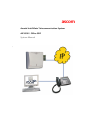
Ascotel IntelliGate Telecommunication System
AIP 6350 / Office 35IP
System Manual
a
AIP 6350 / Office 35IP
Contents
1
1.1
1.2
Safety Instructions . . . . . . . . . . . . . . . . . . . . . . . . . . . . . . . . . . . . . . . . 5
About the Products. . . . . . . . . . . . . . . . . . . . . . . . . . . . . . . . . . . . . . . . . 5
Guidelines to this System Manual . . . . . . . . . . . . . . . . . . . . . . . . . . . . . . 6
2
System Description . . . . . . . . . . . . . . . . . . . . . . . . . . . . . . . . . . . . . . . 7
3
3.1
3.1.1
3.1.2
3.1.3
3.2
3.3
3.3.1
3.3.2
3.3.3
3.4
3.4.1
3.4.2
3.4.3
Initial Installation . . . . . . . . . . . . . . . . . . . . . . . . . . . . . . . . . . . . . . . . . 9
Planning . . . . . . . . . . . . . . . . . . . . . . . . . . . . . . . . . . . . . . . . . . . . . . . . . 9
Designing the System . . . . . . . . . . . . . . . . . . . . . . . . . . . . . . . . . . . . . . 10
Assigning Call Numbers and IP Addresses . . . . . . . . . . . . . . . . . . . . . . . 11
Network Planning . . . . . . . . . . . . . . . . . . . . . . . . . . . . . . . . . . . . . . . . . 13
Installation . . . . . . . . . . . . . . . . . . . . . . . . . . . . . . . . . . . . . . . . . . . . . . 14
Configuring . . . . . . . . . . . . . . . . . . . . . . . . . . . . . . . . . . . . . . . . . . . . . 14
Adding AIP Card(s) and IP Terminals . . . . . . . . . . . . . . . . . . . . . . . . . . . 15
Configuring the Default Gateway . . . . . . . . . . . . . . . . . . . . . . . . . . . . . 16
AIP Configuring . . . . . . . . . . . . . . . . . . . . . . . . . . . . . . . . . . . . . . . . . . 17
Commissioning . . . . . . . . . . . . . . . . . . . . . . . . . . . . . . . . . . . . . . . . . . . 17
Checking the Installation. . . . . . . . . . . . . . . . . . . . . . . . . . . . . . . . . . . . 17
Functional Test . . . . . . . . . . . . . . . . . . . . . . . . . . . . . . . . . . . . . . . . . . . 18
Troubleshooting . . . . . . . . . . . . . . . . . . . . . . . . . . . . . . . . . . . . . . . . . . 18
4
4.1
4.2
4.2.1
4.3
4.3.1
4.4
4.5
4.5.1
4.5.2
4.5.2.1
4.5.2.2
4.6
4.6.1
4.6.2
4.6.3
IP Terminal Office 35IP. . . . . . . . . . . . . . . . . . . . . . . . . . . . . . . . . . . . 20
Expansion Options . . . . . . . . . . . . . . . . . . . . . . . . . . . . . . . . . . . . . . . . 20
Installation . . . . . . . . . . . . . . . . . . . . . . . . . . . . . . . . . . . . . . . . . . . . . . 20
Power Over LAN . . . . . . . . . . . . . . . . . . . . . . . . . . . . . . . . . . . . . . . . . . 21
Configuration . . . . . . . . . . . . . . . . . . . . . . . . . . . . . . . . . . . . . . . . . . . . 22
Configuring IP Addresses . . . . . . . . . . . . . . . . . . . . . . . . . . . . . . . . . . . 22
Initialization and Restart of an IP Terminal . . . . . . . . . . . . . . . . . . . . . . . 23
Registering the IP Terminal with the System . . . . . . . . . . . . . . . . . . . . . 24
Registering Process . . . . . . . . . . . . . . . . . . . . . . . . . . . . . . . . . . . . . . . . 24
Registering Strategies . . . . . . . . . . . . . . . . . . . . . . . . . . . . . . . . . . . . . . 25
Systematic Strategy. . . . . . . . . . . . . . . . . . . . . . . . . . . . . . . . . . . . . . . . 25
The Plug-and-Play Strategy . . . . . . . . . . . . . . . . . . . . . . . . . . . . . . . . . . 26
Handling the IP terminals . . . . . . . . . . . . . . . . . . . . . . . . . . . . . . . . . . . 26
Replacing an IP terminal . . . . . . . . . . . . . . . . . . . . . . . . . . . . . . . . . . . . 26
Connecting an IP Terminal Elsewhere . . . . . . . . . . . . . . . . . . . . . . . . . . 27
Expanding the System with IP Terminals . . . . . . . . . . . . . . . . . . . . . . . . 28
3
AIP 6350 / Office 35IP
5
5.1
5.2
5.3
5.4
5.5
5.5.1
5.6
5.6.1
5.7
5.7.1
5.7.2
5.7.3
5.7.4
5.7.5
Expansion Card AIP 6350. . . . . . . . . . . . . . . . . . . . . . . . . . . . . . . . . . 29
AIP Card . . . . . . . . . . . . . . . . . . . . . . . . . . . . . . . . . . . . . . . . . . . . . . . . 29
DRS Module . . . . . . . . . . . . . . . . . . . . . . . . . . . . . . . . . . . . . . . . . . . . . 30
Component Placement Example . . . . . . . . . . . . . . . . . . . . . . . . . . . . . . 31
Installation of the AIP Card . . . . . . . . . . . . . . . . . . . . . . . . . . . . . . . . . . 32
Connection on the AIP Card . . . . . . . . . . . . . . . . . . . . . . . . . . . . . . . . . 33
V.24 Connection . . . . . . . . . . . . . . . . . . . . . . . . . . . . . . . . . . . . . . . . . 34
Commissioning the AIP Card . . . . . . . . . . . . . . . . . . . . . . . . . . . . . . . . 35
Changing the IP Address of the AIP Card via V.24. . . . . . . . . . . . . . . . . 36
Handling the AIP card . . . . . . . . . . . . . . . . . . . . . . . . . . . . . . . . . . . . . . 36
Fitting and Removing an AIP Card. . . . . . . . . . . . . . . . . . . . . . . . . . . . . 36
Replacing an AIP Card . . . . . . . . . . . . . . . . . . . . . . . . . . . . . . . . . . . . . 37
Fitting an AIP Card to a Different Slot . . . . . . . . . . . . . . . . . . . . . . . . . . 37
Retrofitting an AIP card with DRS modules.. . . . . . . . . . . . . . . . . . . . . . 38
Initialization and Restart of the AIP Card . . . . . . . . . . . . . . . . . . . . . . . . 38
6
6.1
6.1.1
6.1.2
6.1.3
6.2
6.3
6.3.1
6.3.2
Network Environment. . . . . . . . . . . . . . . . . . . . . . . . . . . . . . . . . . . . 39
Network Requirements . . . . . . . . . . . . . . . . . . . . . . . . . . . . . . . . . . . . . 39
Delay and Jitter . . . . . . . . . . . . . . . . . . . . . . . . . . . . . . . . . . . . . . . . . . . 40
Bandwidth Management . . . . . . . . . . . . . . . . . . . . . . . . . . . . . . . . . . . 41
Security . . . . . . . . . . . . . . . . . . . . . . . . . . . . . . . . . . . . . . . . . . . . . . . . 41
Prioritising . . . . . . . . . . . . . . . . . . . . . . . . . . . . . . . . . . . . . . . . . . . . . . 42
Bandwidth Control . . . . . . . . . . . . . . . . . . . . . . . . . . . . . . . . . . . . . . . . 43
Bandwidth Control Based on the Reference Model . . . . . . . . . . . . . . . . 44
Static Routes. . . . . . . . . . . . . . . . . . . . . . . . . . . . . . . . . . . . . . . . . . . . . 46
7
7.1
7.2
7.3
7.4
7.5
7.6
7.6.1
7.6.2
7.6.3
7.6.4
7.6.5
Annex . . . . . . . . . . . . . . . . . . . . . . . . . . . . . . . . . . . . . . . . . . . . . . . . . 48
Overview of System Limits. . . . . . . . . . . . . . . . . . . . . . . . . . . . . . . . . . . 48
Initialisation Values for IP Addresses . . . . . . . . . . . . . . . . . . . . . . . . . . . 48
Reference of AIMS Parameters . . . . . . . . . . . . . . . . . . . . . . . . . . . . . . . 49
Permanent Network Parameters . . . . . . . . . . . . . . . . . . . . . . . . . . . . . . 52
Applications, Protocols and Ports . . . . . . . . . . . . . . . . . . . . . . . . . . . . . 53
Software Upload. . . . . . . . . . . . . . . . . . . . . . . . . . . . . . . . . . . . . . . . . . 54
Upload Process . . . . . . . . . . . . . . . . . . . . . . . . . . . . . . . . . . . . . . . . . . . 54
Preparing the Upload . . . . . . . . . . . . . . . . . . . . . . . . . . . . . . . . . . . . . . 55
Uploading. . . . . . . . . . . . . . . . . . . . . . . . . . . . . . . . . . . . . . . . . . . . . . . 56
Uploading via an External FTP Server . . . . . . . . . . . . . . . . . . . . . . . . . . . 57
Upload Termination . . . . . . . . . . . . . . . . . . . . . . . . . . . . . . . . . . . . . . . 58
Index . . . . . . . . . . . . . . . . . . . . . . . . . . . . . . . . . . . . . . . . . . . . . . . . . . 59
4
AIP 6350 / Office 35IP
1
Safety Instructions
To exclude risk to people or goods, the following instructions must be observed.
1.1
About the Products
Purpose
The products AIP 6350 and Office 35IP expand the functionality of Ascotel IntelliGate and are to be used for that purpose exclusively.
User group
All installation and maintenance work is to be carried by authorized qualified personnel only.
Necessary documentation
To ensure that the products are handled correctly and safely, it is essential that
you consult this Manual. The instructions and notes contained in the Manual must
be observed.
Besides this System Manual the following documents are also required:
• Ascotel IntelliGate System Manual
• Office 35IP Operating Instructions
Data protection
Uncoded phone calls in the network can be recorded and played back using the
appropriate equipment. For this reason it is preferable to use your own leased
lines for WAN links or to encode the IP packets using for example VPN (Virtual Private Network).
For the port configuration of the firewall see the Chapter "Applications, Protocols
and Ports", page 53.
Safety Instructions
5
AIP 6350 / Office 35IP
1.2
Guidelines to this System Manual
Purpose
This System Manual describes the products AIP 6350 and Office 35IP, and how to
handle them. Other AIP versions are not described here. Please refer to the separate product documents.
Target readership
This System Manual is aimed at the persons listed under "User group"
(see page 5).
Conventions
The abbreviation "AIP" is used throughout the text instead of the full designation
"AIP 6350".
The term "IP terminal" is used throughout the text instead of the designation
"Office 35IP".
The abbreviation "AIP card" is used throughout the text instead of the full designation "AIP 6350 expansion card".
Warnings
Special pictograms are used to signal areas of particular risk to people or equipment.
Hazard:
Failure to observe information identified in this way can put people and
hardware at risk through electrical shock and short-circuits/defects
respectively.
Warning:
Failure to observe information identified in this way can cause the product or module to malfunction.
Note:
Failure to observe information identified in this way can lead to equipment faults or malfunctions or affect the performance of the system.
6
Safety Instructions
AIP 6350 / Office 35IP
2
System Description
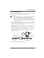
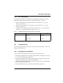
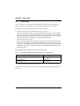
The joint use of the two IP components, namely the AIP 6350 IP interface card and
the Office 35IP system terminal, makes the IP infrastructure available to telephony, and expands the Ascotel IntelliGate platform to the IP data network.
The Office 35IP system terminal is a fully fledged IP terminal with the complete
range of features of an Office 35. It can be operated anywhere in the IP data network, provided the connection to the PBX complies with the quality criteria
required for VoIP (Voice over IP).
Like any Office system terminal, Office 35IP communicates with the PBX via the
AD2 protocol. The features and user prompting are identical to those of the
Office 35.
The AIP 6350 is the PBX's Ethernet interface to the Office 35IP system terminals.
The expansion card from the AIP family has been designed specially for this application.
Both the Office 35IP and the AIP 6350 are configured and updated using the
AIMS management software. All the settings can be made both offline and online
with the usual operating interface.
haz1349aaxxa0
Office 35IP
Office 35
AD2
Office 35IP
LAN 1
LAN 2
Fig. 1:
AD2 via IP
AIP 6350
AD2
Office 35IP and AIP 6350 expand the Ascotel IntelliGate platform to the IP network
System Description
7
AIP 6350 / Office 35IP
This key expansion option translates into a whole range of advantages for the
user:
• Networked, remote workstations can be integrated at low cost into the internal
telephone system, without compromising the ease with which phone calls are
made. Unlike a connection via the public telephone network, no call charges
are incurred and users can be reached as internal subscribers.
• Many features that are restricted when a remote subscriber is integrated as a
virtual subscriber can be used to the full, e.g. call diversions, Voice Mail, Courtesy, text messages, announcements.
• In the case of smaller branch offices the customer can dispense with using an
additional PBX in the branch.
• When expanding an existing infrastructure with new connections for PC and
phones there is no need to expand the phone lines.
Note:
As a result of the expansion of the Ascotel IntelliGate platform to the IP
data network the network used becomes part of the Ascotel IntelliGate
system. The communication quality therefore depends directly on the
network quality (in the same way as the road network influences the
delivery quality of a haulage company).
8
System Description
AIP 6350 / Office 35IP
3
Initial Installation
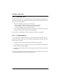
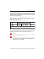
This Chapter guides you through the processes used for expanding a PBX with
Office 35IP terminals (referred to in the following as IP terminals). With the aid of
the reference model you will be taken through the stages of planning, installation,
configuration and commissioning.
haz1350aaxxa0
PBX
PSTN
AIP 6350
IPI
Router 2
LAN 2
Office 35IP
Fig. 2:
3.1
Router 1
LAN 1
WAN
Office 35IP
Reference model
Planning
The aim of the planning phase is to provide all the data necessary for installing,
configuring and putting the system into operation.
The following Instructions assume that an Ascotel IntelliGate telecommunications
system is already in operation, with a networked organisational structure.
Initial Installation
9
AIP 6350 / Office 35IP
3.1.1
Designing the System
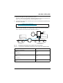
The following describes the procedure for defining the number of IP terminals you
want and the AIP expansion cards required for this purpose (see "Expansion Card
AIP 6350", page 29):
1. Specify the number of IP terminals.
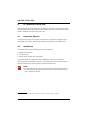
2. Determine the number of voice channels required on the AIP based on the
anticipated traffic volume. Please note that during a call connection each IP
terminal involved requires a call channel to the PBX, as each connection is
routed via the PBX (Fig. 3).
3. Determine the number of AIP cards required (see "Overview of System Limits", page 48):
– The maximum number of AIP cards that can be fitted depends on the PBX
model.
– One AIP card supports up to 16 IP terminals.
– The maximum number of simultaneously active voice channels per AIP card
depends on the DRS modules fitted.
4. Assign each IP terminal to an AIP card (each IP terminal must later be permanently assigned to a fixed AIP card during addressing).
5. Check to make sure that the PBX system limits are not exceeded (see "Overview of System Limits", page 48):
– Number of admissible AIP cards.
– Number of admissible AD2 interfaces. One AIP card occupies 16 AD2 interfaces (see Ascotel IntelliGate System Manual).
– Number of admissible subscribers on the PBX (see Ascotel IntelliGate System Manual)
haz1351aaxxa0
PBX
500
501
PSTN
AIP 6350
IPI
Router 2
LAN 2
521
Fig. 3:
10
Router 1
LAN 1
WAN
522
511
512
513
Call connection between 2 IP terminals
Initial Installation
AIP 6350 / Office 35IP
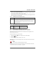
Tab. 1:
System design based on the example of the reference model
Design
Explanation
PBX model
Ascotel IntelliGate 2025 / 2045 / 2065
IP terminals
5
Voice channels
5
AIP Cards
1
DRS modules
1 DRS-08
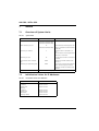
3.1.2
All terminals are able to make and
receive calls simultaneously
max. 8 voice channels
Assigning Call Numbers and IP Addresses
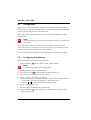
The following describes the procedure for sketching the IP terminals into your network's current layout and assigning the call numbers and IP addresses.
Note:
The system operates with permanently assigned IP addresses. DHCP is
not supported.
1. Sketch the IP terminals into your network's current layout.
All the routers, gateways, firewalls and WAN links between AIP and the IP terminals should be visible along with their IP addresses and subnet masks.
2. Enter the call numbers of the IP terminals.
3. Enter the IP addresses of the IP terminals and AIP cards.
The IP addresses must not have a relation to the call numbers. For the initialisation values of the IP addresses see the Chapter "Initialisation Values for IP
Addresses", page 48.
4. For each IP terminal enter the IP address of its allocated AIP card.
5. Enter the gateway address for each IP terminal. The gateway address is the
terminal-side IP address of the router that forms the transition to another LAN
area with IP terminals.
Initial Installation
11
AIP 6350 / Office 35IP
haz1352aaxxa0
PBX
500
501
PSTN
AIP 6350
IPI
192.168.104.101
Router 2
LAN 2
192.168.111.200
521
192.168.111.121
Router 1
WAN
LAN 1
192.168.104.200
522
511
512
513
192.168.104.111 192.168.104.112 192.168.104.113
192.168.111.122
Subnet-Mask: 255.255.255.000
Fig. 4:
Call numbers and IP addresses on the reference model
Tab. 2:
Addressing the IP terminals based on the example of the reference model
Call number
IP address
Subnet mask
AIP card
Gateway address
511
192.168.104.111
255.255.255.000
192.168.104.101
192,168,104,200 (router 1)
512
192.168.104.112
255.255.255.000
192.168.104.101
192,168,104,200 (router 1)
513
192.168.104.113
255.255.255.000
192.168.104.101
192,168,104,200 (router 1)
521
192.168.111.121
255.255.255.000
192.168.104.101
192,168,111,200 (router 2)
522
192.168.111.122
255.255.255.000
192.168.104.101
192,168,111,200 (router 2)
12
Initial Installation
AIP 6350 / Office 35IP
3.1.3
Network Planning
The following describes the procedure for checking your network and planning
the type of communications between AIP and the IP terminals.
Note:
– Please note that the expertise of an experienced network engineer is
crucial for assessing and optimising the network environment.
– We strongly recommend that you examine the network using a special
check-list, which you can download from our support page (ascotel.ascom.ch). Our specialists will be happy to assist you on the basis
of the completed check-list.
1. Check whether your network environment complies with our recommendations ("Bandwidth Management", page 41); if not, please take the necessary
measures to comply with the requirements.
2. Determine the prioritisation method in accordance with the Chapter "Prioritising", page 42.
With regard to initialisation values ToS is activated and CoS deactivated
(TOS is recommended if the voice connection is to be set up via a WAN link.
CoS prioritises voice traffic at the level of the switches).
3. Plan the bandwidth control in accordance with the Chapter "Bandwidth
Management", page 41.
haz1356aaxxa0
PBX
500
501
PSTN
G.729
521
IPI
511
Bandwidth Area 2
Fig. 5:
Bandwidth control:
max. 12 voice channels
G.711
WAN
522
Codec:
G.711
AIP 6350
Codec:
G.729
Bandwidth control:
max. 4 voice channels
512
513
Bandwidth Area 1
Network planning based on the reference model
Initial Installation
13
AIP 6350 / Office 35IP
3.2
Installation
The aim of the installation phase is to:
• Fit the AIP card(s) and connect them to the network.
• To connect the IP terminals to the power supply and the network.
• Enter the addresses on the IP terminals.
Proceed as follows:
1. Install the AIP card(s) as indicated in the instructions in the Chapter "Expansion Card AIP 6350", page 29.
2. Install the IP terminals as indicated in the Chapter "IP Terminal Office 35IP",
page 20.
3.3
Configuring
The aim of the configuration phase is to define and set all the system parameters
using AIMS.
You can carry out the settings online directly on the PBX or prepare all the settings
in the offline mode and then load them onto the PBX. To do so please refer to the
AIMS online help.
You need to have System Manager or Installer authorisation to have access to the
configuration data.
14
Initial Installation
AIP 6350 / Office 35IP
3.3.1
Adding AIP Card(s) and IP Terminals
The following describes the procedure for complementing the AIMS master data
with the AIP cards and IP terminals.
1. In offline mode add the required number of AIP cards (card configuration;
CM_1_1_2). Make sure the slot selected in AIMS matches the slot actually
used in the system.
Once you have stored your inputs, AIMS will create 16 virtual user-network
interfaces1) with 2 connection possibilities each (MSN 1 and MSN 2) for each
AIP card. As a preconfiguration process AIMS automatically creates subscriber
data including call numbers on all MSN-1 connections.
2. Assign the names and correct call numbers to the subscribers preconfigured
by AIMS (CM_1_1_3_Interface Configuration).
3. Assign the IP addresses to the subscribers in accordance with the layout used
in the planning phase (CM_1_4_5_IP Terminals). Tab. 3 shows the settings
based on the example of the reference model.
4. Enter the IP address and subnet mask of the AIP card (CM_1_4_5_AIP Card).
Tab. 4 shows the settings based on the example of the reference model
Tab. 3:
Assignment of user-network interface – IP address based on the example of the reference model
IP Terminal
User-network interface
IP address
511
5.1-1
192.168.104.111
512
5.2-1
192.168.104.112
513
5.3-1
192.168.104.113
521
5.4-1
192.168.111.121
522
5.5-1
192.168.111.122
Tab. 4:
IP address and subnet mask of the AIP card based on the example of the reference
model
AIP card 1
IP address
Subnet mask
1
192.168.104.101
255.255.255.000
1)
Only 8 subscribers are preconfigured on the Ascotel IntelliGate 2025. Additional subscribers have to be
created manually on the MSN 2 connection of the user-network interfaces.
Initial Installation
15
AIP 6350 / Office 35IP
3.3.2
Configuring the Default Gateway
To be able to reach IP terminals in other LAN areas, you need to enter the IP
address of the router via which the LAN area of the AIP is to be exited (default
gateway). This entry is superfluous if AIP and all the IP terminals are located in the
same LAN area.
You can define different default gateways for each individual IP terminal or for
groups of IP terminals. As only one default gateway is used in most cases, in the
following enter one default gateway for all registered IP terminals. For more information please refer to the Chapter "Static Routes", page 46:
1. Create a static route (CM_1_4_5_Static Routes).
2. Enter the IP address "0.0.0.0".
– "0.0.0.0" covers all the registered IP terminals.
3. Enter the subnet mask "0.0.0.0".
– "0.0.0.0" covers all the LAN areas and subnets.
4. Enter the IP address of the default gateway.
Tab. 5:
Default gateway based on the example of the reference model
Static route
IP address
Subnet mask
Default gateway
1
0.0.0.0
0.0.0.0
192.168.104.200
16
Initial Installation
AIP 6350 / Office 35IP
3.3.3
AIP Configuring
The following describes the procedure for configuring AIP based on the data
determined during the planning phase ("Network Planning", page 13).
1. Check the settings of the general network parameters (CM_1_4_5_AIP
Cards). See also Tab. 6.
2. Configure the parameters for prioritising the voice data (CM_1_4_5_AIP
cards). See also Tab. 6.
3. Configure the parameters for bandwidth control (CM_1_4_5_IP Terminals
and CM_1_4_5_Bandwidth Areas). See also Tab. 17.
Tab. 6:
AIP Settings based on the example of the reference model
AIMS menu
Parameters
Parameter values1)
CM_1_4_5_AIP Cards
On/Off
On
Ethernet
Automatic
VLAN
1
1)
Dejitter Buffer
Automatic
Buffer Size
60
Here they all correspond to the initialisation values
3.4
Commissioning
The aim of commissioning is to obtain a correctly functioning system. For this we
suggest a functional test.
3.4.1
Checking the Installation
Check the following points before starting with the functional test:
• Have the IP terminals been successfully commissioned as indicated in the Chapter "IP Terminal Office 35IP", page 20?
• Has the AIP card been successfully commissioned as indicated in the Chapter
"Expansion Card AIP 6350", page 29 (Link LED lit)?
• Has the AIMS configuration been carried out in full and has the configuration
data been loaded onto the PBX?
• Has the configuration of the switches and routers been adapted?
Initial Installation
17
AIP 6350 / Office 35IP
3.4.2
Functional Test
For the functional test we recommend that you put the system into operation on
a trial basis and check its operational suitability using a structured feedback from
all users. Proceed as follows:
1. Check the following points on each IP terminal:
– Do you obtain a dial tone when you pick up the handset?
– Are you able to set up a connection from the terminal?
– Can a connection to the terminal be set up?
2. In the initial operating phase check the call capacity and the speech quality by
asking the users to inform you of their experiences.
If the result is not satisfactory, have the network checked by specialists.
3.4.3
Troubleshooting
Try and ascertain whether the cause of the error originates in the PBX, the AIP,
the network, the IP terminal or in the interplay between these components. If the
fault appears to lie with.
• .. the PBX, please refer to the Ascotel IntelliGate System Manual.
• .. the network, call in a specialist to help you check the network configuration
and the network-related settings.
• .. the AIP or an IP terminal, check all the settings and connections as explained
this Manual.
The table below lists the most common error messages displayed on the IP terminal and provides pointers on how to remedy them.
18
Initial Installation
AIP 6350 / Office 35IP
Tab. 7:
Troubleshooting based on the display on the IP terminal
Error indication
Error
"Could not register"
IP connection between AIP card and IP Check AIP:
• Functionality check in accordance
terminal cannot be set up
with chapter "Expansion Card
Ethernet connection between AIP
AIP 6350", page 29).
card and IP terminal cannot be set up
• IP address AIP
• IP address of IP terminal
• IP Address of default gateway
"No connection to AIP"
Measures
Check IP terminal:
• IP Address of default gateway
• IP address AIP
• Own IP address
Check network:
• Switch configuration
• Router configuration
• Firewall configuration
"Too many IP-Phones"
The AIP card is already fitted to the
system limit with other IP terminals.
Can PBX be expanded with other AIP
cards?
"Trying to register" or
"Not configured"
No subscriber data allocated
Check AIP/PBX:
• Allocation of IP address to port
• Allocation of port to call number
"Unknown error"
General system error
Contact support
Display does not respond
Local fault on IP terminal
Restart IP terminal
Initial Installation
19
AIP 6350 / Office 35IP
4
IP Terminal Office 35IP
Like any Office system terminal, the system terminal Office 35IP communicates
with the PBX via the AD2 protocol. The features and user prompting are on the
whole1) identical to those of the Office 35.
4.1
Expansion Options
2 expansion keypads and one alpha keyboard or 3 expansion keypads can be
connected to an Office 35IP (see Operating Instructions for the Office 35IP).
4.2
Installation
The Office 35IP has the following external connections:
• Network connection
• PC connection
• Mains power supply unit connection
The terminal has an integrated switch (100BaseT), which can be used for
connecting the workstation computer. This means there is no need to install a
separate network connection point to operate the terminal.
Note:
The integrated switch is to be used exclusively for the operation of a PC.
– Do not connect any other terminals such as IP terminals, switches,
hubs, printers or servers.
1)
20
The system limits are described in chapter "Overview of System Limits", page 48.
IP Terminal Office 35IP
AIP 6350 / Office 35IP
PC
LAN
haz1354aaxxa0
Fig. 6:
Connections on the Office 35IP
To install the Office 35IP proceed as follows:
1. Connect the IP terminals to the power supply.
To do so, first plug the mains connector into the connection socket and only
then connect the RJ45 connector to the terminal's socket.
2. Address the IP terminals in accordance with the instructions in the chapter
"Configuring IP Addresses", page 22.
3. Connect the IP terminals to the network.
As soon as the terminal is connected to the network, it will attempt to register
with the AIP card (see "Registering Process", page 24).
4.2.1
Power Over LAN
If your network supports Power-Over-LAN as per IEEE 802.3af, the Office 35IP can
be powered via the network connecting cable and the mains power supply-unit
is not required (PIN 4/5 and 7/8 on the RJ7 connection).
If the IP terminal is connected to the power supply both via Power over LAN and
the mains power supply unit, it will be powered by whichever source was
connected first.
IP Terminal Office 35IP
21
AIP 6350 / Office 35IP
4.3
Configuration
Equipment and subscriber-specific settings can be made by the user himself via
the terminal or by the system administrator via AIMS. These settings are described
in the Operating Instructions for the Office 35IP.
The IP addresses are entered locally on the terminal by the Installer or System
Administrator.
Note:
The IP addresses are to be entered before the IP terminal is connected to
the network.
The IP addresses remain stored even when the equipment is disconnected.
This means that it is not necessary for the IP terminals to be configured on site;
instead they can be configured prior to the installation.
The menu prompting for entering the IP addresses is only available in English.
4.3.1
Configuring IP Addresses
Proceed as follows to configure the IP addresses:
1. Press the END key
END
until the display reads "Offline Mode".
Note:
Calls cannot be conducted in offline mode.
2. Use the Foxkey to select "Administration".
3. Scroll with the key
MENU
to the desired IP address (see Tab. 8).
4. Select the desired IP address using the Foxkey.
5. Select "Change", to adapt the IP address:
– Enter all 12 decimal places of the IP address (so for IP address 192.16.3.101
for example, enter the digit sequence "192.016.003.101").
– Use the
keys to navigate to the left and right.
6. Confirm the input with "OK".
7. Adapt the other IP addresses in the same way.
8. Press the END key
, if you adapted all IP addresses. The display reads
"Restart Office 35IP?"
END
22
IP Terminal Office 35IP
AIP 6350 / Office 35IP
9. Select "Yes" to activate the settings.
The IP terminal registers with the AIP card, providing it is already connected
to the network, and the offline mode is exited.
If the IP terminal is not yet connected to the network, it will register with the
AIP card as soon as it is connected.
Tab. 8:
IP Addresses in the Local Configuration Menu
IP addresses
Explanation
IP-Adress
IP address and subnet mask of the IP terminal
GW-Adress
Gateway address: The IP router address, is the terminal-side IP address of the router that
forms the transition to another LAN area with IP terminals (see Tab. 9). If all the IP
terminals are in the same LAN area, 000.000.000.000 can be used as the gateway
address (first-start value).
AIP-Adress
IP address of the AIP card
Tab. 9:
Gateway addresses using the example of the reference model
LAN area
IP terminals
Gateway address
1
511, 512, 513
192,168,104,200 (router 1)
2
521, 522
192,168,111,200 (router 2)
4.4
Initialization and Restart of an IP Terminal
Restarting the IP terminal initializes the local software and re-registers the IP
terminal with the AIP card.
Proceed as follows to carry out a restart:
1. Press the END key
2. Press the
MENU
END
until the display reads "Offline Mode".
key.
3. Use the Foxkey to select "Restart" and "Yes".
Alternatively you can also unplug the power cord under the terminal and then
reconnect it.
Note:
Calls cannot be conducted during the restart.
Initializing the IP terminal sets all the addresses to the initialization values (see
"Initialisation Values for IP Addresses", page 48).
IP Terminal Office 35IP
23
AIP 6350 / Office 35IP
Proceed as follows to carry out an initialization:
1. Initiate a restart. The boot procedure is initiated.
2. Press simultaneously the key MENU and the key "0", 5 seconds after start of
the boot procedure. Hold the key until the display reads "Set factory
defaults".
3. Release the keys. The IP terminal is started with the initialization values.
4.5
Registering the IP Terminal with the System
The IP terminal registers on the system itself after a restart (see "Initialization and
Restart of an IP Terminal", page 23).
4.5.1
Registering Process
The IP terminal registers with the AIPcard whose IP address is configured under
"AIP Address" in the terminal, and notifies it of its own IP address.
The AIP software checks whether the same IP address has already been assigned
to a user-network interface with subscriber data in the AIMS configuration, and
responds as follows depending on the result:
• The IP address has already been assigned to a user-network interface:
– The IP terminal is assigned to the same user-network interface.
– The user-network interfaces including user name and call number are
available to the terminal.
– The registering process is completed.
• The IP address has not been assigned to any user-network interface:
– The IP terminal is assigned to the next available user-network interface with
preconfigured subscriber data (user-network interfaces without assigned
subscriber data are not active).
– The preconfigured subscriber settings including user name and call number
are available on the terminal, and the registering process is completed.
24
IP Terminal Office 35IP
AIP 6350 / Office 35IP
4.5.2
Registering Strategies
The registering process allows 2 strategies for registering IP terminals with the
system:
• The systematic strategy
• The Plug-and-Play Strategy
4.5.2.1
Systematic Strategy
The assignment of the IP address to user-network interface and phone number is
determined before the installation.
Use this procedure is you are planning the installation systematically:
1. Fitting and registering the AIP card.
2. Use AIMS to enter the IP address of the AIP card.
3. Use AIMS to enter the user name and phone number and assign them to the
user-network interfaces.
4. Use AIMS to assign the IP addresses of the IP terminals to the user-network
interfaces.
5. Configure the local IP addresses in the IP terminals.
6. Connect the IP terminals to the network. The IP terminals are registered and
their configuration is then completed.
This procedure is also used in the Chapter "Initial Installation", page 9.
IP Terminal Office 35IP
25
AIP 6350 / Office 35IP
4.5.2.2
The Plug-and-Play Strategy
The definitive assignment of the IP address to user-network interface and phone
number is determined after the installation.
1. Fitting and registering the AIP card.
2. Use AIMS to enter the IP address of the AIP card.
3. Configure the local IP addresses in the IP terminals.
4. Connect the IP terminals to the network.
The IP addresses of the IP terminals are assigned one after the other to the
available user-network interfaces and then registered.
The IP terminals are ready to operate. However, you will not know in advance
which phone number is assigned to an IP terminal.
5. Checking the phone numbers on the IP terminals.
6. Adapting the phone numbers and the remaining subscriber data using AIMS.
4.6
Handling the IP terminals
This Chapter describes how to replace or move IP terminals during operation, and
how to expand the system with other IP terminals.
4.6.1
Replacing an IP terminal
The following describes the procedure for replacing an IP terminal. For this the
PBX does not have to be taken out of operation:
1. Unplug all the connectors on the IP terminals.
2. Install the replacement terminal as indicated in the Chapter "IP Terminal
Office 35IP", page 20.
Make sure you enter the same IP addresses as those configured in the terminal
you have replaced.
3. Carry out a connection check.
26
IP Terminal Office 35IP
AIP 6350 / Office 35IP
4.6.2
Connecting an IP Terminal Elsewhere
The following describes how to change the point at which an IP terminal is
connected without changing the call number, subscriber name or the terminal
settings. For this the PBX does not have to be taken out of operation:
If the IP addresses of the IP terminal, the default gateway and the AIP card can be
taken over unchanged, proceed as follows:
1. Unplug all the connectors on the IP terminals.
2. Install the IP terminal in accordance with chapter "Installation", page 20,
without adapting the IP addresses.
3. Carry out a connection check.
If the IP addresses must be adapted, proceed as follows:
1. Unplug all the connectors on the IP terminals.
2. Adapt the IP addresses in the AIP configuration with AIMS.
3. Use AIMS to check the settings of the set codec, the allocated bandwidth area
and the allocated static routes.
4. Install the IP terminal in accordance with chapter "Installation", page 20 and
adapt the IP terminal in accordance with chapter "Configuring IP Addresses",
page 22.
5. Carry out a connection check.
IP Terminal Office 35IP
27
AIP 6350 / Office 35IP
4.6.3
Expanding the System with IP Terminals
The following describes how to expand the system with additional IP terminals.
For this the PBX does not have to be taken out of operation:
1. Check to make sure that none of the following limits are exceeded as a result
of the expansion:
– Admissible number of system terminals on the PBX (a PBX upgrade may be
necessary)
– Admissible number of IP terminals per AIP card (another AIP card may be
necessary).
– Maximum number of simultaneously active voice channels on the AIP card
(the DRS modules may have to be removed).
– Maximum number of simultaneously active voice channels in the
bandwidth areas concerned (bandwidth may have to be increased).
2. Specify the call numbers and IP addresses of the new terminals and configure
them in the PBX using AIMS.
3. Install the IP terminals as indicated in the Chapter "IP Terminal Office 35IP",
page 20.
4. Use AIMS to check the settings of the set codec, the allocated bandwidth area
and the allocated static routes.
5. Carry out a connection check.
28
IP Terminal Office 35IP
AIP 6350 / Office 35IP
5
Expansion Card AIP 6350
The extension card AIP 6350 is identically as the extension card AIP 6400,
however is provided with another software.
5.1
AIP Card
AIP cards are installed in an Ascotel IntelliGate 2025, 2045 or 2065. Depending
on the system one or more AIP cards can be used.
Tab. 10:
Number of AIP cards supported
PBX
Possible number of AIP cards
Ascotel IntelliGate 2025
1
Ascotel IntelliGate 2045
2
Ascotel IntelliGate 2065
4
The AIP cards fitted can be loaded with the same or with different AIP software.
If they are loaded with the same AIP software, the maximum number of processable voice channels is added up.
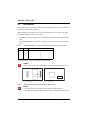
Slot 1
Slot 2
Host-Bus
Fig. 7:
haz1307aaxxa0
10/100 BT
Autosense
Network LEDs
System LED
Reset
V.24
DRS Modules
AIP card with DRS module slots
Expansion Card AIP 6350
29
AIP 6350 / Office 35IP
5.2
DRS Module
DRS modules are AIP-specific modules that are fitted to the AIP card. An AIP card
contains 2 slots for DRS modules.
DRS modules are required for the real-time processing of voice data. Two DRS
modules of different sizes are available:
• The DRS-04 module is capable of processing up to 4 voice channels simultaneously
• The DRS-08 module is capable of processing up to 8 voice channels simultaneously
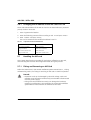
Tab. 11:
Component placement variants for DRS modules and number of voice channels
DRS-04
DRS-08
Maximum number of voice channels per AIP card
1
-
4
2
-
8
-
1
8
1
1
12
-
2
12 (!)
It is not significant how the module slots are fitted.
Notes:
A maximum of 12 voice channels can be processed for each AIP card.
haz1297aaxxa0
Front view
Fig. 8:
Rear view
DRS module (rear view with components for DRS-08 only)
Notes:
– An AIP card has to be fitted with at least one DRS module.
– AIP cards are supplied without DRS modules. Please order separately.
30
Expansion Card AIP 6350
AIP 6350 / Office 35IP
5.3
Component Placement Example
An Ascotel IntelliGate 2065 is fitted with 3 AIP cards:
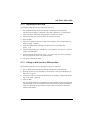
Tab. 12:
Ascotel IntelliGate 2065 with 3 AIP cards
DRS-04
DRS-08
Voice channels
IP terminals
AIP card 1
1
1
12
16
AIP card 2
1
1
12
16
AIP card 3
1
-
4
16
Total
3
2
28
48
Expansion Card AIP 6350
31
AIP 6350 / Office 35IP
5.4
haz0001aaxxa0
Installation of the AIP Card
Warning:
During the entire installation procedure, it is mandatory to observe the
electrostatic discharge (ESD) precautions. The creation of an anti-static
environment is highly recommended.
Fitting the PBX with an AIP card:
1. Fitting an AIP card with DRS modules.
2. Disconnect the PBX from the power supply.
3. Fit the AIP card into the PBX as described in the Chapter "Fitting Expansion
Cards" in the "Installation" Part of the Ascotel IntelliGate System Manual.
Hazard:
– Expansion cards can be damaged by electrical voltage. Cards and
modules are to be fitted or removed only once the PBX is disconnected
from the power supply!
– Fitting cards and modules incorrectly can damage the hardware,
resulting in malfunctions. The instructions in the Ascotel IntelliGate
System Manual must therefore be followed to the letter.
The AIP card is automatically registered during a restart or initialization.
32
Expansion Card AIP 6350
AIP 6350 / Office 35IP
5.5
Connection on the AIP Card
The AIP card is connected by a switch to the network. The PBX does not have to
be switched off for this.
For the connection the following cable is to be used:
• Straight (1:1 through-connected) twisted-pair Ethernet cable
• Category 5 or higher
• With RJ-45 connectors at both ends.
haz1080aaxxc0
PBX
RJ45
PC
RJ-45
AIP
Switch
PC
Fig. 9:
PC switch – AIP card connection
Tab. 13:
Pin assignment of the straight cable
Switch
RJ45 Connector, 8 pin
Expansion Card AIP 6350
AIP
Signal
Pin
Data flow
Tx+
1
Tx-
2
Rc+
3
3
Tx+
Rc-
6
6
Tx-
haz1081aaena0
Pin
Signal
1
Rc+
2
Rc-
33
AIP 6350 / Office 35IP
5.5.1
V.24 Connection
The serial interface (V.24) enables support specialists to monitor the traffic data.
It has no function in normal operation.
A crossed cable (null modem cable) is used to connect the PC to the AIP card via
the serial interface (V.24).
Tab. 14:
Signal
Pin assignment of the crossed cable
DTE
Data flow
DTE
D-Sub-9
Socket
Signal
D-Sub-9
Socket
D-Sub-25
Socket
3
2
TXD
TXD
3
RXD
2
2
3
RXD
SGND
5
5
7
SGND
AIP
PC
PC
haz1083aaena0
3-TXD
2-RXD
5-SGND
1 6 2 7 3 8 4 9 5
haz1084aaxxa1
Fig. 10:
Pin assignment on the D-Sub-9 connector
Flow control on the PC is to be set on "XON / XOFF". Hardware handshake RTS /
CTS is not supported.
34
Expansion Card AIP 6350
AIP 6350 / Office 35IP
5.6
Commissioning the AIP Card
When the PBX is switched on with a newly installed AIP card, the green system
LED on the AIP card should start flashing (see Fig. 7, page 29). The network LEDs
have the following functions:
Tab. 15:
Functions of the LEDs on the AIP card
LED name
Colour
Function
Link
green
• lit when connected to the network
• flashes irregularly during data exchange
100 Mbit
green
• lit when connected to a 100 Base-T network
• off when connected to a 10 Base-T network
Collision
red
Collision detection
The correct installation of the AIP card on the network can be tested from a PC
using the Ping utility. To operate the Windows Ping utility proceed as follows:
1. Select "Run" from the Start menu.
2. In the input field enter the Ping command: "ping <IP address>".
3. Confirm with "ENTER".
If there is no response to the Ping command, the AIP card is not detected.
There may be several reasons for this:
• Faulty physical connection between the AIP card and the network.
• The IP address or subnet mask of the PC or of the AIP card is incorrect or not
identical.
• There is a malfunction in the network or on the PC.
After successful commissioning, AIP can be configured using AIMS.
Expansion Card AIP 6350
35
AIP 6350 / Office 35IP
5.6.1
Changing the IP Address of the AIP Card via V.24
The IP and subnet address of the AIP card can be corrected without a password
prompt via the V.24 access.
1. Start a hyperterminal session
2. Enter the following command line according to Tab. 16 and press "Enter":
3. Enter "reboot" and press "Enter"
The card is started and the modified IP address is read in.
Tab. 16:
Important Terminal Command Lines
Function
Command line
Show current IP address
ipaddr eth0 show
Change IP address
ipaddr eth0 <IP address>
Show current subnet mask
ipmask eth0 show
Change subnet mask
ipmask eth0 <subnet mask>
5.7
Handling the AIP card
This Chapter describes the procedure for replacing or offsetting an AIP card,
and what happens with the AIP configuration data during this process.
5.7.1
Fitting and Removing an AIP Card
Follow the instructions in the Ascotel IntelliGate System Manual (Part 7, "Fitting
and Removing Cards") for fitting or removing an AIP card on a PBX in operation.
Hazard:
– Expansion cards can be damaged by electrical voltage. Cards and
modules are to be fitted or removed only once the PBX is disconnected
from the power supply!
– Fitting cards and modules incorrectly can damage the hardware,
resulting in malfunctions. The instructions in the Ascotel IntelliGate
System Manual must therefore be followed to the letter
36
Expansion Card AIP 6350
AIP 6350 / Office 35IP
5.7.2
Replacing an AIP Card
The following describes how to replace an AIP card:
1. Use an AIMS Download to save the AIP configuration data (backup).
(As this may no longer be possible if the card is defective, it is advisable to
keep backups of the latest configuration on AIMS at all times.)
2. Replace the AIP card as described in the previous Chapter.
3. Start the PBX.
4. Log in with AIMS on-line on the PBX. The message "HW configuration has
been changed" appears.
5. Start the configuration manager and select the card configuration
(CM_1_1_2).
6. Select the replaced card in the column "Card (system)" and click on "Confirm
System Configuration".
7. Switch onto AIP configuration (CM_1_4_5_AIP cards), check the configuration and unlock the card ("AIP Card On/Off").
8. Carry out a functional check.
5.7.3
Fitting an AIP Card to a Different Slot
The following describes how to change the slot of an AIP card:
1. Use an AIMS Download to save the AIP configuration data (backup).
2. Remove the AIP card as described in the Chapter "Fitting and Removing an
AIP Card", page 36.
3. Fit the AIP card in its new slot as described in the Chapter "Fitting and Removing an AIP Card", page 36.
4. Start the PBX.
The AIP configuration data is retained. The port numbers of the interfaces and
their allocation to the IP addresses of the IP terminals are adapted automatically. The allocation of the subscriber data to the port numbers has to be
adapted with AIMS:
Expansion Card AIP 6350
37
AIP 6350 / Office 35IP
5. Use AIMS to allocate the call numbers of the IP terminals to the new port
numbers (CM_1_1_3_Subscriber) so the subscriber data can be re-assigned.
6. Check the configuration using AIMS and unlock the card (CM_1_4_5_AIP
Cards, Setting "AIP Card On/Off").
7. Carry out a functional check.
5.7.4
Retrofitting an AIP card with DRS modules.
An AIP card can also be retrofitted with DRS modules:
1. Disconnect the PBX from the power supply.
2. Remove the AIP card as indicated in the Ascotel IntelliGate System Manual.
3. Fit the DRS modules.
4. Reinsert the AIP card as indicated in the Chapter "Fitting and Removing an
AIP Card", page 36 and switch the PBX back on.
The DRS module is automatically detected by the system.
5.7.5
Initialization and Restart of the AIP Card
When the PBX is first initialised the AIP configuration data is also reset to its initialisation values. The IP addresses of the AIP card and the IP terminals are not
reset.
During a PBX restart the AIP card is also re-initialized. The configuration data is
retained.
A restart of the AIP card on its own can be obtained using AIMS (CM_1_4_5_AIP
Cards).
38
Expansion Card AIP 6350
AIP 6350 / Office 35IP
6
Network Environment
This Chapter provides background information on the main network characteristics you need to take into consideration. It is assumed here that a network is
already available.
Please note that the expertise of an experienced network engineer is crucial for
optimising the network environment.
6.1
Network Requirements
As a result of the expansion of the Ascotel IntelliGate platform to the IP data network the network used becomes part of the Ascotel IntelliGate system. The communication quality therefore depends directly on the quality of service (QoS) and
the network topology (in the same way as the road network influences the delivery quality of a haulage company). The general requirements are as follows:
• Ethernet 10 Base-T or 100 Base-T
• The use of switches rather than hubs
• Sufficient bandwidth
In other respects we recommend the use of all available methods for reducing the
bandwidth and for ensuring a high quality of service(see the following chapters).:
Network Environment
39
AIP 6350 / Office 35IP
6.1.1
Delay and Jitter
High delay and jitter values have a considerably detrimental effect on the quality
of speech.
The delay values of the voice packets should be kept as small as possible. The following methods are used to reduce delay and compensate jitter:
• Prioritising voice packets over other data packets: See the Chapter ("Prioritising", page 42).
• Jitter management:
The time fluctuation between the arrival of individual packets is controlled with
a dejitter buffer in the Office 35IP and in the AIP 6350 and does not require any
additional control in the network (see page 49, Tab. 28). Jitter management is
time-critical. The greater the jitter buffer, the greater the delay values.
• Fragmentation of the IP packets:
Large data packets increase the delay of waiting voice packets. If the packets
are fragmented, prioritised voice packets can be sent between the packet fragments. Possible methods: MTU scaling, MCML-PPP (multilink-PPP).
• Frame length of the voice packets:
The smaller the frame length of the voice packets is, the smaller the delay values generated, i.e. the greater the bandwidth requirement. For this reason we
recommend that the frame length of AIP and Office 35IP be kept relatively
small within the LAN area with a high bandwidth and relatively large for WAN
connections with a short bandwidth (settings, see Tab. 28, page 49).
40
Network Environment
AIP 6350 / Office 35IP
6.1.2
Bandwidth Management
The available bandwidth can be limited, especially on WAN links. The bandwidth
control of AIP 6350 prevents call connections from being set up if there is too little
bandwidth available (see "Bandwidth Control", page 43). The following methods
help to reduce the bandwidth requirement:
• Voice compression:
In the LAN area with sufficient bandwidth it makes sense to use a codec without compression (G.711) as the speech quality is better. Compressing codecs
are used to advantage in WAN areas with limited bandwidth. See the Chapter
"Bandwidth Control", page 43.
• Compressing the IP header:
Voice packets are relatively small compared with their header (large overhead).
On a point-to-point connection between 2 routers the 40 byte header can be
considerably compressed. This means the resources of the available bandwidth
can be used more sparingly. This setting is carried out in the router. Possible
method: cRTP.
6.1.3
Security
Uncoded phone calls in the network can be recorded and played back using the
appropriate equipment. For this reason it is preferable to use your own leased
lines for WAN links or to encode the IP packets using for example VPN (Virtual Private Network).
For the port configuration of the firewall see the Chapter "Applications, Protocols
and Ports", page 53.
Network Environment
41
AIP 6350 / Office 35IP
6.2
Prioritising
If the IP network is to guarantee the bandwidth required for call connections,
voice packets have to be given priority compared with other data packets.
The system supports the following prioritisation methods:
• Expanded IP frames as per IEEE 802.1p/Q (CoS, Layer 2):
AIP and IP terminals use the prioritisation field in the expanded frame header
to specify the priority. Prioritisation is effected in the switches. All the switches
used must therefore support prioritisation as per IEEE 802.1p/Q and be configured accordingly for the method to be supported effectively.
• Type of Service (ToS, Layer 3):
AIP and IP terminals use the ToS field (8 priority levels) of the IP header to specify the priority (tagging). Prioritisation is effected in the routers or in the Layer
3 switches. The routers used must therefore support ToS prioritisation and be
configured accordingly. The router handles non-prioritised data packets with
standard priority.
Both prioritisation methods can be used simultaneously.
Tab. 17:
Prioritisation settings based on the example of the reference model
Parameters
Parameter value1)
CoS Priorisation
Off
CoS Priorisation Level
5 Interactive Media
ToS Priorisation Level
5 CRITIC_ECP
ToS Service Type
8 Low Latency
1)
Here they all correspond to the initialisation values
The settings are effective for both the AIP and the IP terminals (see also page 49,
Tab. 28 ).
42
Network Environment
AIP 6350 / Office 35IP
6.3
Bandwidth Control
The maximum number of call connections possible simultaneously can be limited
using AIMS to ensure that the maximum number of call connections set up does
not exceed the available bandwidth.
The amount of bandwidth required by a call connection depends on the voice
compression method. This method can be set for each individual IP terminal by
selecting the correspond codec. The selected codec determines the bandwidth
necessary for each call connection.
Tab. 18:
Codecs supported and their bandwidth requirements
Codec
Bandwidth voice
Effective bandwidth (without IP header compression)
in relation to the frame length
Speech quality
10 ms
20 ms
30 ms
G0.711
64 kbit/s
111 kbit/s
90 kbit/s
80 kbit/s
max. 4.5 MOS
G.729
8 kbit/s
55 kbit/s
32 kbit/s
24 kbit/s
max. 4 MOS
G.711 is uncompressed, has small delay values (provided a small frame length has been set) and a high
speech quality (the MOS scale ranges from 1 to 5). This codec should be given priority whenever there is
sufficient bandwidth available. If the bandwidth is limited, G.729 is used to advantage.
As the bandwidth size available in the IP network is not the same everywhere, IP
terminals can be grouped into areas with the same bandwidth. The number of call
connections can be limited for each area. Once the limit is reached, no further
connections are permitted. The caller will obtain the congestion tone.
Note:
To optimise the available bandwidth, the same codec should be used for
IP terminals within a given bandwidth area.
Note:
Prioritised voice packets on a WAN link with tight design limits can slow
down the data traffic to intolerable levels. For this reason sufficient
bandwidth has to be included in the calculations when designing the
maximum number of voice channels.
Network Environment
43
AIP 6350 / Office 35IP
6.3.1
Bandwidth Control Based on the Reference Model
The following describes the procedure for defining codecs based on the example
of the reference model and for setting up the bandwidth areas. An available
bandwidth of 128 kbit/s is assumed as the measurement basis for the WAN link.
haz1355aaxxa0
PBX
500
501
PSTN
AIP 6350
IPI
Router 2
LAN 2 10 Mbit/s
521
Fig. 11:
Router 1
10 Mbit/s
WAN
522
128 kbit/s
511
512
LAN 1
513
Bandwidth resources based on the example of the reference model
Proceed as follows:
1. Divide the IP terminals into 2 areas (CM_1_4_5_Bandwidth Areas):
– Area 1: IP terminals with call numbers 511, 512 and 513
– Area 2: IP terminals with call numbers 521, 522
2. Specify the codec for the IP terminals in area 2.
As there is only little bandwidth available between AIP and the IP terminals of
area 2, G.729 and a frame length of 30 ms is a good choice (CM_1_4_5_IP
Terminals).
3. Calculate how many voice channels can be open simultaneously over the
WAN link:
128 kbit/s (WAN bandwidth)
24 kbit/s (call channel with G.729 / 30ms)
= 5 voice channels
This means that in the ideal case 5 voice channels can be open simultaneously.
In real practical circumstances, however, 4 voice channels should be expected.
4. Limit the maximum possible number of voice channels for area 2 to 4 (the
number of call connections that can then be set up over the WAN link is
shown in Tab. 20, page 46).
44
Network Environment
AIP 6350 / Office 35IP
5. Specify the codec for the IP terminals in area 1.
As there is sufficient bandwidth available between AIP and the IP terminals of
area 1, G.711 can be used with a frame length of 10 ms.
6. Calculate how many voice channels can be open simultaneously between AIP
and the IP terminals:
10 Mbit/s (LAN 1 bandwidth)
111 kbit/s (call channel with G.711 / 10 ms)
= 90 voice channels
In the maximum configuration with 4 fully equipped AIP cards the system supports 48 voice channels. This means that in area 1 the number of possible
voice channels can be set to the maximum value 12.
haz1356aaxxa0
PBX
500
501
PSTN
G.729
521
Codec:
G.711
AIP 6350
Codec:
G.729
Bandwidth control:
max. 4 voice channels
IPI
Bandwidth control:
max. 12 voice channels
G.711
WAN
522
511
512
513
Bandwidth Area 1
Bandwidth Area 2
Fig. 12:
Bandwidth control based on the example of the reference model
Tab. 19:
Configuration of bandwidth control based on the example of the reference model
Parameters
Parameter value
IP terminal 511, 512 and 513:
• Codec
G.7111)
• Frame Length
10 ms
• Bandwidth Area
1
IP terminal 521 and 522:
• Codec
G.729
• Frame Length
30 ms
• Bandwidth Area
2
Bandwidth Area 1:
• Name
LAN 1
Network Environment
45
AIP 6350 / Office 35IP
Parameters
Parameter value
• Voice Channels (max.)
12
Bandwidth Area 2:
• Name
LAN 2
• Voice Channels (max.)
4
1)
Corresponds to the initialisation value
Tab. 20:
Number of possible call connections
Call connections
Channels
required for each
connection
Channels
available
Possible
connections
Between PBX and area 1
1
12
12
Within area 1
2
12
6
Between area 1 and 2 (via WAN link)
1
4
4
Within area 2
2
4
2
6.3.2
Static Routes
To be able to reach IP terminals in other LAN areas, you need to enter the IP
address of the router via which the LAN area of the AIP is to be exited (default
gateway).
With the aid of static routes you can define default gateways for each individual
IP terminal or for groups of IP terminals.
If an IP terminal can be reached via several paths with different default gateways,
a static route can be defined for each of the default gateways. AIP tries out the
first Static route. If a connection is not obtained, it tries the next one.
Proceed as follows to set up the static routes:
1. Create a static route (AIP; CM_1_4_5_Static Routes).
2. Enter the IP address of an IP terminal or the address range for several IP terminals of a subnet (see Tab. 21).
3. Enter the subnet mask in accordance with Tab. 21.
4. Enter the address of the gateway via which the subnet is exited on the way to
the destination subnet (default gateway).
5. Repeat the above steps for each static route. You can also define several static
routes for the same IP terminals.
46
Network Environment
AIP 6350 / Office 35IP
Tab. 21:
Entering IP address ranges
Subnet mask
IP address
Address range
255.255.255.255
xxx.xxx.xxx.xxx
1 IP address
255.255.255.0
xxx.xxx.xxx.0
xxx.xxx.xxx.1 to xxx.xxx.xxx.254
255.255.0.0
xxx.xxx.0.0
xxx.xxx.1.1 to xxx.xxx.254.254
255.0.0.0
xxx.0.0.0
xxx.1.1.1 to xxx.254.254.254
0.0.0.0
0.0.0.0
1.1.1.1 to 254.254.254.254
Tab. 22:
Static route settings based on the example of the reference mode, variant 1
Static route
IP address
Subnet mask
Default gateway
1
0.0.0.0
0.0.0.0
192,168,104,200 (router 1)
All the IP terminals will be searched for in their own subnet and everywhere behind the gateway. This is the
most common and simplest variant.
Tab. 23:
Static route settings based on the example of the reference mode, variant 2
Static route
IP address
Subnet mask
Default gateway
1
192.168.111.0
255.255.255.000
192,168,104,200 (router 1)
IP terminals 521 and 522 will be searched for in the range from 192.168.111.001 to 192.168.111.254.
Tab. 24:
Static route settings based on the example of the reference mode, variant 3
Static route
IP address
Subnet mask
Default gateway
1
192.168.111.121
255.255.255.255
192,168,104,200 (router 1)
2
192.168.111.122
255.255.255.255
192,168,104,200 (router 1)
IP terminals 521 and 522 will be addressed dedicatedly.
Network Environment
47
AIP 6350 / Office 35IP
7
Annex
7.1
Overview of System Limits
Tab. 25:
System limits
Number (max.)
Remarks
AIP Cards
1 (Ascotel IntelliGate 2025) AIP variants can be combined
2 (Ascotel IntelliGate 2045)
4 (Ascotel IntelliGate 2065)
IP AD2 interfaces per card
16
Virtual interfaces without physical con8 (Ascotel IntelliGate 2025) nection. Considered as AD2 interfaces
by the PBX
IP terminals per interface
2
Connection MSN 1 and MSN 2 (virtual).
Each connection can be assigned the IP
address of an IP terminal.
IP terminals per card
16
On initialisation all MSN-1 connections
are seized.
Voice channels active simultaneously
4/8/12
Depends on the DRS modules used.
See Tab. 11
IP terminals per closed user group
4/8/12
The number of IP terminals registered
with a closed user group must not
exceed the number of available voice
channels
CTI applications
7.2
Tab. 26:
First-party CTI is not supported
Initialisation Values for IP Addresses
Initialisation Values for IP Addresses
Address
Initialisation values
AIP card:
• IP address
• Subnet mask
192.168.104.023
255.255.255.000
IP terminal:
• IP address
• Subnet mask
• AIP address
• Gateway address
192.168.104.033
255.255.255.000
192.168.104.023
000.000.000.000
48
Annex
AIP 6350 / Office 35IP
7.3
Reference of AIMS Parameters
Listed below are the parameters that can be viewed and modified using AIMS,
together with a brief explanation.
Tab. 27:
Legend
Symbols
Meaning
*
Initialisation value
(..)
Display, not modifiable
<..>
Expected input
Tab. 28:
CM_1_4_5_IP Terminals
Parameters
Parameter values
Explanation
Call Number
(<Subscriber No.>)
Call number of the allocated subscriber
Name
(<Name>)
Name of the allocated subscriber
IP Address
<IP address>
IP address of the IP terminal
Codec
*G.711a
G.711u
G.729
G.711a uses the German tone signalling
method; G.711u, the U.S. method.
Setting valid for all call connections
between this IP terminal and the AIP card.
Frame Length
*10/20/30 ms
Setting valid for all call connections
between this IP terminal and the AIP card
(see "Delay and Jitter", page 40).
Bandwidth Area
1 to 10
Assignment of the IP terminal to a bandwidth area
Enabled
(Yes/No)
An IP terminal can only be assigned once
subscriber data has been created for a connection.
State
(Registered/Not Registered/
Upload/No Terminal
Shows the IP terminal's current status
Application SW Version
(<Software version>)
Indicates the version of the application software. To update the application software,
see page 54
Boot SW Version
(<Software version>)
Indicates the version of the boot software
Annex
49
AIP 6350 / Office 35IP
Tab. 29:
CM_1_4_5_AIP Cards
Parameters
Parameter values
Explanation
Slot
(<Slot No.>)
Slot in which the current AIP card is located.
On/Off
*On/Off
Off: Card not active; assigned IP terminals
unobtainable
State
(Barred/Prebarred/
In operation/SW Upload)
Indicates the current card status
SW Version
(Software version)
Indicates the card's software version
Active Voice Channels
(0 to 12)
Indicates how many voice channels are activ
MAC address
(<address>)
MAC address of the AIP card
IP Address
<address>
IP address of the AIP card.
The card has to be restarted whenever the IP
address is changed
Subnet Mask
<address>
Subnet of the AIP card.
The card has to be restarted whenever the subnet mask is changed
Ethernet
*Autosense/10BaseT/
100BaseT
Sets the AIP card and the IP terminals to the
Ethernet connection type used.
CoS Priorisation
On/*Off
Activates Layer-2 prioritisation (see "Prioritising", page 42)
CoS Priorisation Level
0 Best Effort
1 Background
2 Standard
3 Excellent Effort
4 Streaming Multimedia
*5 Interactive Multimedia
6 interactive Voice
Specifies the priority of the voice packets when
CoS prioritisation is activated.
Level 5 has to be set for a good speech quality.
Setting is valid for AIP card and its IP terminals.
VLAN-ID
*1 to 4094
The AIP card and its IP terminals can be assigned
to a virtual LAN (VLAN) or form such a LAN. The
VLAN is identified by its ID.
VLAN must be supported by all switches. Setting is valid for AIP card and its IP terminals.
ToS Priorisation Level
0 Best Routine
1 Priority
2 Immediate
3 Flash
4 Flash Override
*5 Critical
6 Internetwork Control
7 Network Control
ToS IP Precedence: Specifies Layer-3 priority for
the voice packets (see "Prioritising", page 42).
Level 5 has to be set for a good speech quality.
Levels 6 and 7 are reserved for the network
administration and should not be used.
Setting is valid for AIP card and its IP terminals.
50
Annex
AIP 6350 / Office 35IP
Tab. 29:
CM_1_4_5_AIP Cards (continuation)
Parameters
Parameter values
Explanation
ToS Service Type
0 Normal Service
2 High Reliability
4 High Throughput
*8 Low Latency
Setting is valid for AIP card and its IP terminals.
Dejitter Buffer
Static
*Dynamic
Dynamic: During the connection the buffer size
is continually adapted to the network conditions. Minimum size as defined by the "Buffer
Size" setting.
Static: Fixed buffer size as defined by the
"Buffer Size" setting.
Setting valid for AIP card only. The dynamic
dejitter buffer of the IP terminals does not have
to be configured especially.
Buffer Size
0 to 250 ms; *60 ms
We recommend a maximum setting of 200 ms,
otherwise the delay values become too high.
Setting valid for AIP card only. The dynamic
dejitter buffer of the IP terminals does not have
to be configured especially.
Tab. 30:
CM_1_4_5_Static Routes
Parameters
Parameter values
Explanation
Static Route
1 to 10
Reference number
IP address
<IP address>
Address of one or more IP terminals.
For syntax see "Static Routes", page 46.
Subnet Mask
<Subnet mask>
Subnet or subnet area in which the routing
destinations are located. For syntax see
"Static Routes", page 46
Default Gateway
<IP address>
Gateway via which the subnet of the AIP
card is exited on the way to the destination
address.
Tab. 31:
CM_1_4_5_Bandwith Areas
Parameters
Parameter values
Explanation
Bandwidth Area
1 to 40
Reference number
Name
<Name (max. 20 characters)> Name of bandwidth area.
Voice Channels (max.)
1 to 12
Annex
Maximum number of voice channels open
simultaneously
51
AIP 6350 / Office 35IP
7.4
Permanent Network Parameters
The following parameters are set permanently and cannot be modified.
Tab. 32:
Permanent parameters that cannot be set
Parameters
Parameter values
Silence Suppression
Off
Echo Cancellation
On
52
Annex
AIP 6350 / Office 35IP
7.5
Applications, Protocols and Ports
The following table describes the applications, protocols and ports used by the
host.
Host 1
Direction
Protocol
Layer 4
Applications, protocols and ports used
Application
Tab. 33:
Host 2
Port
Voice data
RTP
UDP
AIP
Signalling
AD2
TPKT
TCP
AIP
FTP
Control
TCP
FTP
Data
SW Upload AIP/IP terminal
Emergency SW Upload
(Boot Loader)
5004-5027
Port
<-> IP terminal
30000
8065
<-
IP terminal
1024-1044
60000-65000
->
IP terminal
8065
FTP
21
Server1)
<-
AIP/
IP terminal
60000-65000
TCP
FTP
server
20
->
AIP/IP terminal
60000-65000
TFTP
Control
UDP
TFTP
server
69
<-
AIP
1027
TFTP
Data
TCP
TFTP
server
1024-2000
->
AIP
1027
Echo reply / request (ping)
ICMP 8/0 -
PC/AIP
-
<->
AIP/
IP terminal
-
Test with echo server2)
RTP
UDP
PC
5004-5027
<->
AIP/
IP terminal
7
Access via Telnet
Telnet
TCP
PC
1024-4000
->
AIP/
IP terminal
23
1)
FTP server of the PBX or external FTP server
2)
Used in connection with Traffic Monitoring Tools
Annex
53
AIP 6350 / Office 35IP
7.6
Software Upload
This Chapter describes the software uploading procedure for AIP 6350 and
Office 35IP.
AIP and IP terminals implement software which has to be adapted in the course
of the product's further development (application software). The latest application software can be loaded on to the terminals using the AIMS Upload Manager.
7.6.1
Upload Process
The Upload process for IP terminals is described below. The Upload process for
AIP cards follows the same pattern:
• Initialization phase:
From the Upload Manager select the IP terminals to be loaded with the new
application software. Start the Upload: the Upload Manager copies the software file to the PBX's FTP storage medium (Fig. 13; [1]) or to an external FTP
server and initiates the Upload process on the first terminal [2].
• Execution phase:
The IP terminal retrieves the software file from the FTP server of the PBX [3] or
from an external FTP server, loads it into its memory [4] and restarts the terminal, which in turn activates the new application software.
• Monitoring:
The Upload Manager checks and registers the Upload status during the execution phase; once one IP terminal has been fully updated, the Upload Manager
triggers the same process for the next IP terminal.
The Upload is completed once all the IP terminals have been loaded with the new
software and restarted.
54
Annex
AIP 6350 / Office 35IP
PBX
500
[1]
501
PSTN
AIMS
AIP
[2]
[3]
WAN
haz1364aaxxa0
522
[4]
Fig. 13:
7.6.2
Software Upload
Preparing the Upload
The following preparations have to be made before you start the Upload:
1. Make sure you inform all users of the time at which the upload is scheduled
to be carried out as phone calls cannot be made or received while the new
software is being initialised.
2. Use AIMS to make a backup of the configuration data prior to the Upload.
3. Deactivate the AIP cards (CM_1_4_5_AIP_Card, "On/Off=Off").
If some connections are still active, the card will first be automatically prebarred so that no new connections can be set up. As soon as all the connections are cleared down, the card is barred.
Annex
55
AIP 6350 / Office 35IP
7.6.3
Uploading
To load different types of application software, first load the version for the PBX
software, then the one for AIP, and finally the version for the IP terminals. In each
case always wait until the current Upload is fully completed before initiating a
new one.
Next load the IP terminals with a new application software. For this, use the PBX
internal FTP server (normal case). The process for loading the AIP application software follows the same pattern and is not described separately.
The new software is supplied in the form of a Zip file. To load the IP terminals with
the application software, proceed as follows:
Warning:
Make sure that during the Upload there is no interruption to the power
supply either to the PBX or to the IP terminals.
1. Copy the zip file onto the PC using the Upload Manager or onto a drive in the
network to which you have access with the Upload Manager.
2. Start the AIMS Upload Manager.
3. From the "Configuration" tab select the PBX, enter the password and configure the PBX connection as indicated in the Ascotel IntelliGate System Manual
(Part 7, Operation and Maintenance).
4. Select the option "PBX as FTP Server".
5. Switch to the "IP Terminals" tab. The "Application Software" field displays
the name of the file with the application software for the IP terminals.
6. From the list of available IP terminals select those you want to update.
7. Start the Upload by clicking "Upload".
8. You can check the progress and status of the Upload on the "Status" tab.
The Upload is completed once all the IP terminals have been loaded with the
new software and restarted.
Once the Upload is completed the AIP cards are automatically reactivated and
restarted.
9. On the "IP Terminal" tab check the software version and the following states
for each IP terminal that was scheduled for the Upload:
– "Status=Registered"
– "Upload=Successfully Completed".
56
Annex
AIP 6350 / Office 35IP
7.6.4
Uploading via an External FTP Server
The load process of the application software of the IP terminals from an external
FTP server is described below. The process for loading the AIP application software
follows the same pattern and is not described separately.
The new software is available in the form of individual files on an external FTP
server. To load the IP terminals with new application software, proceed as follows:
Warning:
Make sure that during the Upload there is no interruption to the power
supply either to the PBX or to the IP terminals.
1. Start the AIMS Upload Manager.
2. From the "Configuration" tab select the PBX, enter the password and configure the PBX connection as indicated in the Ascotel IntelliGate System Manual
(Part 7, Operation and Maintenance).
3. On the "Configuration" tab deactivate the option "PBX as FTP Server".
4. Enter the IP address of the external FTP server, the user name and the access
password.
Note:
For the IP address, always enter the complete address in the format
"xxxx.xxxx.xxxx.xxxx". Alias (like e.g.. "pbx1.upload-center.ch") are not
supported.
5. Switch into the tab "IP terminals" and enter in the field "application software" the path and the name of the file with the application software.
6. Start the Upload by clicking "Upload".
The Upload is completed once all the IP terminals have been loaded with the
new software and restarted.
Once the Upload is completed the AIP cards are automatically reactivated and
restarted.
7. On the "IP Terminal" tab check the software version and the following states
for each IP terminal that was scheduled for the Upload:
– "Status=Registered"
– "Upload=Successfully Completed".
Annex
57
AIP 6350 / Office 35IP
7.6.5
Upload Termination
The Upload is terminated if
• .. a predefined time limit (timeout) is exceeded,
• .. the FTP server cannot be accessed,
• .. the power supply is interrupted.
The timeout can be set separately for the IP terminals and the AIP cards in the
"Options/Settings" menu in the Upload Manager. The time indication relates to
the Upload process for an IP terminal or an AIP card.
The upload time required depends greatly on the network's transit rate. The initialisation values are set to an average value and may have to be adjusted.
Tab. 34:
Measures following an Upload termination
Cause of the termination
Measures
Time limits exceeded
• Check to see if the time limits are set too low
• On the "Status" tab check the progress of the Upload. This may help
you to circumscribe possible sources of error.
No access to the FTP server
• Check the configured IP address of the FTP server and the password
entered
• Check to see whether the FTP server is functional
Power supply interrupted
• Try and repeat the Upload. In certain rare instances the AIP card may
no longer respond. In such cases contact the Support.
58
Annex
AIP 6350 / Office 35IP
Index
G
G.711, G0.729
. . . . . . . . . . . . . . . . . . . . . 43
I
B
Initial installation . . . . . . . . . . . . . . . . . . . . .9
Initialisation values . . . . . . . . . . . . . . . . . . . 48
Installation . . . . . . . . . . . . . . . . . . . . . . . . . 14
IP Terminal
Configuration . . . . . . . . . . . . . . . . . . . . 22
Configuring IP Addresses . . . . . . . . . . . 22
Connecting elsewhere . . . . . . . . . . . . . 27
Expansion options . . . . . . . . . . . . . . . . . 20
Handling . . . . . . . . . . . . . . . . . . . . . . . . 26
Initialization and Restart . . . . . . . . . . . . 23
Installation . . . . . . . . . . . . . . . . . . . . . . 20
Power Over LAN . . . . . . . . . . . . . . . . . . 21
Registering on the system . . . . . . . . . . . 24
Registering process . . . . . . . . . . . . . . . . 24
Registering strategies . . . . . . . . . . . . . . 25
Replacing . . . . . . . . . . . . . . . . . . . . . . . 26
System expansion . . . . . . . . . . . . . . . . . 28
Bandwidth control . . . . . . . . . . . . . . . . . . 43
Bandwidth management . . . . . . . . . . . . . . 41
M
C
Mac-address . . . . . . . . . . . . . . . . . . . . . . . 49
MSN . . . . . . . . . . . . . . . . . . . . . . . . . . . . . 49
A
AIP card
Changing the IP address via V.24 . . . . .
Commissioning . . . . . . . . . . . . . . . . . .
Component placement example . . . . .
Connection . . . . . . . . . . . . . . . . . . . . .
DRS module . . . . . . . . . . . . . . . . . . . . .
Handling in operation . . . . . . . . . . . . .
Initialization and Restart . . . . . . . . . . . .
Installation . . . . . . . . . . . . . . . . . . . . . .
on a different slot . . . . . . . . . . . . . . . .
Replace . . . . . . . . . . . . . . . . . . . . . . . .
V.24 . . . . . . . . . . . . . . . . . . . . . . . . . .
Assigning call numbers and IP addresses . .
Checking the installation . . . . . . . . . . . . . .
Codec . . . . . . . . . . . . . . . . . . . . . . . . . . . .
Commissioning . . . . . . . . . . . . . . . . . . . . .
Configuring . . . . . . . . . . . . . . . . . . . . . . .
Configuring AIP . . . . . . . . . . . . . . . . . . . .
Configuring the default gateway . . . . . . .
Connection
IP Terminal . . . . . . . . . . . . . . . . . . . . . .
CoS . . . . . . . . . . . . . . . . . . . . . . . . . . . . .
36
35
31
33
30
36
38
32
37
37
34
11
17
43
17
14
17
16
20
42
D
Delay and jitter . . . . . . . . . . . . . . . . . . . . . 40
Designing the system . . . . . . . . . . . . . . . . 10
DHCP . . . . . . . . . . . . . . . . . . . . . . . . . . . . 11
Network environment . . . . . . . . . . . . . . . . 39
Network Planning . . . . . . . . . . . . . . . . . . .13
Network requirements . . . . . . . . . . . . . . . . 39
P
Permanent Network Parameters . . . . . . . . .52
Planning . . . . . . . . . . . . . . . . . . . . . . . . . . . 9
Ports . . . . . . . . . . . . . . . . . . . . . . . . . . . . . 53
Power Over LAN . . . . . . . . . . . . . . . . . . . .21
Prioritising . . . . . . . . . . . . . . . . . . . . . .42, 49
Protocols . . . . . . . . . . . . . . . . . . . . . . . . . . 53
Q
F
Firewall . . . . . . . . . . . . . . . . . . . . . . . . . . .
Frame length . . . . . . . . . . . . . . . . . . . . . .
FTP server . . . . . . . . . . . . . . . . . . . . . . . . .
Functional test . . . . . . . . . . . . . . . . . . . . .
N
53
49
57
18
QoS . . . . . . . . . . . . . . . . . . . . . . . . . . . . . .42
R
Reference of AIMS parameters . . . . . . . . . .49
59
AIP 6350 / Office 35IP
S
Safety instructions . . . . . . . . . . . . . . . . . . . . 5
Security . . . . . . . . . . . . . . . . . . . . . . . . . . . 41
Static routes . . . . . . . . . . . . . . . . . . . . . . . . 46
System description . . . . . . . . . . . . . . . . . . . . 7
System limits . . . . . . . . . . . . . . . . . . . . . . . 48
T
ToS . . . . . . . . . . . . . . . . . . . . . . . . . . . . . . 42
Troubleshooting . . . . . . . . . . . . . . . . . . . . . 18
U
Updating software . . . . . . . . . . . . . . . . . . . 54
Upload Manager . . . . . . . . . . . . . . . . . . . . 54
V
VLAN . . . . . . . . . . . . . . . . . . . . . . . . . . . . . 49
Voice compression . . . . . . . . . . . . . . . .41, 43
60
© by ascom
Order No.:
Version:
20326473
en_hbg_000_a0