1
f
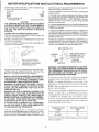
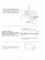
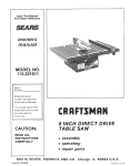
Save This Manual
For Future Reference
,__AIRS
owners
manual
MODEL NO.
113.221620
Serial
Number
Model and serial numLxzrs
may be found at the
left-hand side of the base.
You should record both
model and serial number
in a safe place for future
Use,
FOR YOUR
SAFETY
READ ALL
INSTRUCTIONS
CAREFULLY
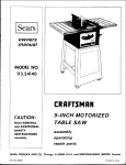
_'__AIRS/ CRRFTSMRN
8 INCH DIRECT
TABLE SA W
DRIVE
• assembly
• operating
• repair
parts
J
Sears, Roebuck
Part No. SP5311
and Co., Hoffman
Estates,
IL. 60179 U.S.A.
Printed in U.S.A.
FULL
If within
material
ONE YEAR
WARRANTY
one year from the date of purchase,
or workmanship,
Sears wil! repair
ON CRAFTSMAN
this Craftsman
Table
it, free of charge.
WARRANTY
SERVICE
IS AVAILABLE
BY SIMPLY
SERVICE
CENTER/DEPARTMENT
THROUGHOUT
This warranty
applies
only
This warranty
gives you
from state to state.
Sears,
while
specific
Roebuck
this
product
legal
rights,
BEFORE USING THE SAW:
WARNING: TO AVOID MISTAKES THAT COULD
CAUSE SERIOUS, PERMANENT INJURY, DO NOT
PLUG THE SAW IN UNTIL THE FOLLOWING STEPS
HAVE BEEN SATISFACTORILY COMPLETED.
2
and alignment
(See pages
8-20).
Learn the use and function of the ON-OFF switch,
guard, spreader, anti-kickback
device, miter gauge,
fence, table insert and blade elevation and bevel
controls. (See page 21).
3. Review and understanding
of all safety instructions
and operating procedures in this manual.
4. Review of the maintenance
methods for this saw.
(See page 32).
Read the following
front of the saw:
_tEAD
Ii
JS[
AND
UNDERSTAND
_,_ AAD
[ DANGER
%A_SLAD[
_tP"_DS
WHEN
_'J'
;_
_ )_
PA'_'F
DANGER
OWNERS
T_4L,
BEFORE
2
_ roc, _(],"
]SAW_,
FORYOUROWN
SAWB_AO_
INSTALLING
MANUAL
label
'
OPERATING
PERF_IA_I
NEvEeREA,
found
OPFRATIONS
SAFETY:
H m£OUND
OR MOVING
on
the
MALJHIN[
_q_[H#,NC,
;a_,VER',&_B_Ar)E
THE SAW:
1. AVOID DANGEROUS
ENVIRONMENT.
Use the
saw in adry place protected
from rain Keep work
area well righted.
2. To avoid injury from unexpected
saw movement:
a. Put the saw on a firm level surface where there
is plenty
of room for handling
and properly
supporting
the workp_ece.
b. Support
the saw so the table
saw does not rock.
c
is level and the
Bolt the saw to the floor if it tends
or slide during normal use.
to siip, walk,
d. When us=ngtabre
extensions
over 24" wide on
any side of the saw, bolt the saw to the floor or
prop up the outer end of the extension
from
the floor to keep the saw from tipping.
3 Put the saw where neither operators
or bystanders must stand in line with the saw blade.
4 GROUND
THE SAW- This saw has an approved
3-conductor
cord and a 3-prong
grounding
type
pt,Jg. The plug fits grounding
type outlets design-
Estates,
in
SEARS
States.
may also have other
and Co., D/817 WA Hoffman
Safety is a combination
of common sense, staying
alert and knowing how your table saw works. Read
this manual to understand this saw.
THE NEAREST
STATES.
is in use in the United
and you
SAW
Saw fails due to a defect
CONTACTING
THE UNITED
SAFETY INSTRUCTIONS
1. Assembly
TABLE
rights
which
vary
IL. 60179
FOR TABLE SAW
ed for 120 volt 15 amp circuits.
The green
conductor
in the cord is the grounding
wire. To
avoid electrocution,
NEVER connect
the green
wire to a live terminal.
5. To avoid injury from electrical
shock, make sure
your fingers do not touch the plug's met31 prongs
when plugging
in or unplugging
the saw.
6. To avoid back injury,
get help or use recommended casters when you need to move the saw.
Always get help if you need to lift the saw. Hold
the saw close to your body. Bend your knees so
you can lift with your legs, not your back.
7. NEVER STAND ON TOOL. Serious injury could
occur if the tool tips or you accidentally
hit the
cutting tool. Do not store anything
above or near
the tool where anyone might stand on the tool to
reach them.
BEFORE EACH USE:
1. Inspect
your
saw.
a. To avoid injury from accidental
starting, unplug
the saw, turn the switch off and remove the
switch
key before
raising
or removing
the
guard,
changing
the cutting
tool, changing
the setup or adjusting
anything.
b. Check for alignment
of moving parts, binding
of moving parts, breakage of parts, mounting,
and any other conditions
that may affect the
way it works. If any part is missing,
bent, or
broken in any way, or any electrical
parts don't
work properly, turn the saw off and unplug the
saw.
c. Replace
damaged,
missing,
or failed parts
before using the saw again
d. Use the sawblade
guard, spreader,
and antikickback
pawls for any thru-sawing
(whenever
the blade comes through
the top of the workp,ece). Make sure the pawls work properly.
Make sure the spreader
is in line with the
sawblade.
e. REM©VE
ADJUSTING
KEYS
AND
WRENCHES.
Form habit of checking
for and
removing
keys and adiusting
wrenches
from
toot before turning
it on.
f. To avoid injury from jams. slips or thrown pieces
(kickback and throwback):
1. USE ONLY RECOMMENDED
ACCESSORIES. Follow the instructions
that come with
the accessories.
Consult the owner's manual
for recommended accessories. The use of
improper accessories may cause risk of injury
to persons.
2. Choose the right blade or cutting accessory
for the material and the type of cutting you
plan to do.
3. Never use grinding wheels, abrasive cut-off
wheels, friction
wheels (metal slitting
blades) wire wheels or buffing wheel. They
can fly apart explosively.
4. Choose and inspect your cutting tool carefully.
a. To avoid cutting tool failure and thrown
shrapnel (broken pieces of blade), use only
8" or smaller blades or other cutting tools
marked for speeds of 3450 rpm or higher.
b. Always use unbroken, balanced blades
designed to fit this saw's 5/8" arbor.
c. When thru-sawing, (making cuts where the
blade comes through the workpiece top)
always use a 8" diameter blade. This keeps
the spreader in closest to the blade.
d. Do not overtighten arbor nut. Use arbor
wrenches to "snug" it securely.
e. Use only sharp blades with properly set
teeth. Consult a professional blade sharpener when in doubt.
f. Keep blades clean of gum and resin.
5. Adjust table inserts flush with the table top.
NEVER use the saw without the proper insert.
6. Make sure all clamps and locks are tight and no
parts have any excessive play.
2. KEEP
WORK
AREA
CLEAN
a. Cluttered
areas and benches invite accidents.
Floor
must
not be slippery
from
wax or
sawdust.
b. To avoid burns or other fire damage, never use
the saw near flammable
liquids,
vapors
or
gases.
Plan ahead to protect
your eyes, hands, face,
ears.
a. To avoid injury, don't do layout, assembly,
or
setup work
on the table while the blade is
spinning.
It could cut or throw anything
hitting
the blade.
AVOID
ACCIDENTAL
STARTING
- Make sure
switch is "OFF" before plugging
saw in.
Plan your work
1. USE THE RIGHT
TOOL
- Don't force tool or
attachment
to do a job it was not designed
for.
2. Dress
for safety:
- Do not wear loose clothing,
gloves,
neckties
or jewelry (rings, wrist watches).
They can get
caught and draw you into moving parts.
- Wear nonslip
- Tie back
long
footwear.
hair.
- Roll long sleeves
above
the elbow
Noise levels vary widely.
To avoid possible
hearing
damage,
wear ear plugs or muffs
when using saw for long periods of time.
Any power saw can throw foreign objects into
the eyes. This can cause
permanent
eye
damage.
Wear safety goggles (not glasses)
that comply with ANSI Z87.1 (shown on package). Everyday
eyeglasses
have only impact
resistant
lenses. They are not safety glasses.
Safety
goggles
are available
at Sears retail
catalog
stores.
Glasses
or goggles
not in
compliance
with ANSI Z87.1 could seriously
hurt you when they break.
WEAR
YOUR
- For dusty operations, wear a dust mask along
with the safety goggles.
3. Inspect your workpiece. Make sure there are no
nails or foreign objects in the part of the workpiece to be cut.
4. Plan yourcut to avoid KICKBACKS and THROWBACKS - when a part or all of the workpiece
binds on the blade and is thrown violently back
toward the front of the saw:
- Never cut FREEHAND: Always use either a rip
fence, miter gauge or fixture to position and
guide the work, so it won't twist, bind on the
blade and kickback.
-Make
sure there's no debris between the
workpiece and its supports.
- When cutting irregularly shaped workpieces,
plan your work so it will not slip and pinch the
blade:
- A piece of molding, for example, must lie
flat or be held by a fixture or jig that will not
let it twist, rock or slip while being cut. Use
jigs, fixtures where needed to prevent workpiece shifting.
- Use a different, better suited type of tool for
work that can't be made stable.
- Use extra caution
with large, very small or
awkward
workpieces:
-Use
extra
supports
(tables,
saw horses,
blocks,
etc.)
for any workpieces
large
enough
to tip when not held down to the
table top. NEVER use another person as a
substitute
for a table extension,
or as additional support for a workpiece
that is longer
or wider then the basic saw table, or to help
feed, support
or pull the workpiece.
- Never confine
the piece being cut off. That
is, the piece NOT against
the fence, miter
gauge or fixture.
Never hold it, clamp
it,
touch
it, or use length stops against
it. It
must be free to move. If confined,
it could
get wedged against
the blade and cause a
kickback
or throwback.
- Nevercut morethan one workpieceat a
time.
-Never turn your table saw "ON" before
clearingeverythingexceptthe workpiece
andrelatedsupportdevicesoff the table,
Plan the way you will push the workpiece
- NEVER
pull the workpiece
finish the cut from the front
c. Wait
a. Use the guard
b. Push loose
stick before
through.
through.
Start and
of the table saw.
2. Remove
keep good
additional
RIP TYPE
the rotation
of the
into the cutting tool
- Always push the workpiece
sawb/ade.
all the way past the
WARNING:
DON'T
LET FAMILIARITY
(GAINED
FROM FREQUENT
USE OF YOUR TABLE SAW)
CAUSE
A CARELESS
MISTAKE.
ALWAYS
REMEMBER
THAT A CARELESS
FRACTION
OF A
SECOND
IS ENOUGH
TO CAUSE
A SEVERE
INJURY.
blade
to stop
instructions
CUTS
,_
before
lifting
the
for
2 'I
II
1. Before
actually
cutting
with the saw, watch
it
while it runs for a short while. If it makes an
unfamiliar
noise or vibrates a lot, stop immediately. Turn the saw off. Unplug the saw. Do not
restart until finding and fixing the problem.
Before
Starling
-To
avoid kickbacks
and slips
make sure the rip fence is parallel
into the blade,
to the sawblade.
- Check theantikickback
pawls. (See BASlCSAW
OPERATION
- USING THE RIP FENCE.)
The
pawls must stop a kickback
once it has started.
Replace
or sharpen
antikickback
pawls when
points become dull.
tool
for the cut
- Plastic and composition
(like hardboard)
materials may be cut on your saw. However,
since
these are usually
quite hard and slippery,
the
antikickback
pawls may not stop a kickback.
Therefore,
be especially
careful in your set-up
and cutting
procedures.
4. KEEP CHILDREN
AWAY. All visitors
should
be
kept a safe distance
from
work.
Make
sure
bystanders
are clear of the saw and workpiece.
5. Let the blade reach full speed before cutting.
6. DON'T FORCE TOOL.
It will do the job better
and safer at its designed
rate. Feed the workpiece
into the blade only fast enough
to let it cut
without
bogging
down or binding.
7. Before freeing any jammed
material:
a. Turn switch "OFF".
b. Unplug
key.
A FEATHERBOARD
can help guide the workpiece. See BASIC SAW OPERATION
- USING
THE RIP FENCE. Always use featherboards
for
any non-thru
rip type cuts.
SAW IS RUNNING
3. Set the cutting tool as low as possible
you're planning.
the guard:
Never rip anything
shorter than 10" long.
When using a push stick or push block,
the
trailing end of the board must be square. A push
stick or block against
an uneven end could slip
off or push the work away from the fence.
- NEVER turn the saw "ON" before clearing
the
table of all tools, wood scraps,
etc., except the
workpiece
and related feed or support
devices
for the cut planned.
2. Make sure the top of the arbor or cutting
turns toward the front of the saw.
inside
a long
NEVER use the miter gauge when ripping.
Use a push stick whenever
the fence is 2 to 6
inches from the blade. Use an auxiliary
fence and
push block whenever
the fence must be within 2
inches of the blade. (See "Basic Saw Operation
Using The Rip Fence" section.)
- As much as possible,
keep your face and body to
one side of the sawblade,
out of line with a
possible
kickback
or throwback.
WHENEVER
trapped
with
saw.
4. Wait for
guard.
footing
- Push the workpiece
against
blade. NEVER feed material
from the rear of the saw.
to stop.
pieces off the table
starting another cut.
switch
3. Unplug
- NEVER
reach in back of the cutting
tool with
either hand to hold down or support
the workpiece,
remove
wood scraps,
or for any other
reason.
- Avoid hand positions
where a sudden slip could
cause fingers or hand to move into asawblade
or
other cutting
tool.
Always
parts
assembly.
c. To remove pieces
1. Turn saw off.
- NEVER put your fingers or hands in the path of
the sawblade
or other cutting
tool.
- DON'T OVERREACH.
and balance.
for all moving
d. Check
blade, spreader
and fence for proper
alignment
before starting,
again.
8. To avoid throwback
of small, cut off pieces:
While
cutting
-To
avoid kickbacks
and slips into the blade,
always push forward on the section of the workpiece between the saw blade and the rip fence.
Never push forward on the piece being cut off.
the saw.
4
additional
instructions
for
CROSS CUT TYPE CUTS
While cutting
-To avoid blade contact, always hold the miter
gauge as shown in the BASIC SAW OPERATIONS - USING THE MITER GAUGE.
Before starting
- NEVER use the rip fence when crosscutting.
- An auxiliary wood facing attached to the miter
gauge can help prevent workpiece twisting and
throwbacks.
Attach it to the holes provided.
Make the facing long enough and big enough to
support your work. Make sure, however, it will
not interfere with the sawblade guard.
- Use jigs or fixtures to help hold any piece too
small to extend across the full length of the miter
gauge face during the cut. This lets you properly
hold the miter gauge and workpiece and helps
keep your hands away from the blade.
GLOSSARY
BEFORE LEAVING THE SAW
1. Turn the saw off.
2. Wait for blade to stop spinning.
3. Make workshop child-proof. Lock the shop. Disconnect master switches. Remove the yellow
switch key. Store it away from children and
others not qualified to use the tool.
4. Unplug the saw.
OF TERMS FOR WOODWORKING
Push Stick
A device used to feed the workpiece
through the saw
during
narrow
ripping
type operations
and help
keep the operator's
hands well away from the blade.
Push Block
A device used for ripping type operations
too narrow
to allow use of a push stick.
Rabbet
A notch in the edge of a workpiece.
Resin
A sticky, sap base substance
that has hardened.
Anti-Kickback
Pawls (AKB)
Device which, when properly
maintained,
is designed to stop the workpiece
from being kicked back at
the operator
during ripping operations.
Arbor
The shaft on which a cutting
tool is mounted.
Crosscut
A cutting
or shaping
operation
made across the
width of the workpiece.
Dado
A non-through
cut which produces
a square sided
notch or trough in the workpiece.
Featherboard
A device which can help guide workpieces
during rip
type operations.
Ripping
A cutting
operation
along the
piece.
Revolutions
Per Minute (RPM)
The numberofturnscompleted
in one minute.
Freehand
Performing
a cut without using a fence, miter gauge,
fixture, hold down or other proper device to keep the
workpiece
from twisting
during the cut.
Gum
A sticky, sap based residue from wood products.
Heel
of the work-
by a spinning
object
Sawblade Path
The area of the workpiece
or table top directly in line
with the part of the workpiece
which will be, or has
been, cut by the blade.
Set
The distance
that the tip of the sawblade
tooth is
bent (or set) outward
from the face of the blade.
Misalignment
of the blade.
Kerf
The amount
of material
removed
by the blade in a
through
cut or the slot produced
by the blade in a
non-through
or partial cut.
Kickback
An uncontrolled
grabbing
and throwing
of the workpiece back toward the front of the saw during a rip
type operation.
Leading
End
The end of the workpiece
operation,
is pushed into
length
Throw-Back
Throwing
of pieces
in a manner
similar
to a kickback.
Thru-Sawing
Any cutting
operation
where
the blade extends
completely
through
the thickness
of the workpiece.
Trailing
End
The workpiece
operation.
which, during a rip type
the cutting
tool first.
end last cut by the blade
in a ripping
Workpiece
The item on which the cutting
operation
is being
done. The surfaces
of a workpiece
are commonly
referred to as faces, ends, and edges.
Molding
A non-through
cut which produces
a special shape
in the workpiece
used for joining
or decoration.
5
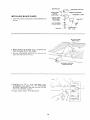
MOTOR SPECIFICATIONS
AND ELECTRICAL
The AC motor used in this saw is a non-reversible type,
with the following specifications:
Amperes ..............................
7.8
Hertz .................................
60
Phase ..............................
Single
RPM ................................
3450
Rotation (viewed from
Sawblade end) ............
Counterclockwise
tool housing at one end and to the ground prong in the
attachment plug at the other end.
This plug requires a mating 3-conductor grounded type
outlet as shown.
If the outlet you are planning to use for this saw is of the
two prong type DO NOT REMOVE OR ALTER THE
GROUNDING PRONG IN ANY MANNER. Use an
adapter as shown and always connect the grounding
lug to a known ground.
CAUTION
THE STARTING RELAY IN THIS SWITCH HOUSING
IS A GRAVITY SENSITIVE TYPE. TO AVOID DAMAGING YOUR MOTOR, NEVER TURN THE POWER ON
UNLESS THE SAW IS UPRIGHT
IN SAWING
POSITION.
CONNECTING
TO POWER SOURCE OUTLET
This saw must be grounded
while in use to protect
operator from electrical shock.
It is recommended that you have a qualified electrician
replace the TWO prong outlet with a properly grounded
THREE prong outlet.
A temporary adapter as shown below is available for
connecting plugs to 2-prong receptacles. The green
grounding lug extending from the adapter must be connected to a permanent ground such as to a properly
grounded outlet box.
the
A temporary adapter as illustrated is available for connecting plugs to 2-prong receptacles. The temporary
adapter should be used only until a properly grounded
outlet can be installed by a qualified electrician.
If power cord is worn or cut, or damaged in any way, have
it replaced immediately.
Your saw is wired for 120 volts and it has a plug that looks
like the one shown below.
3-PRONG
PLUG
GROUNDING
3-PRONG
PLUG
GROUNDING
REQUIREMENTS
LUG
_-
PRONG
ADAPTER
PROPERLY GROUNDED
3-PRONG OUTLET
MAKE SURE THIS IS
CONNECTED
TO A
KNOWN GROUND
2-PRONG
RECEPTACLE
WARNING: THE GREEN GROUNDING LUG EXTENDING FROM THE ADAPTER MUST BE CONNECTED
TO A PERMANENT GROUND SUCH AS TO A PROPERLY GROUNDED OUTLET BOX. NOT ALL OUTLET
BOXES ARE PROPERLY GROUNDED.
Plug power cord of fully assembled saw into 120V properly grounded
type outlet protected
by a 15-amp. time
delay or Circuit-Saver
fuse or circuit breaker.
NOT ALL OUTLETS ARE PROPERLY GROUNDED. IF
YOU ARE NOT SURE THAT YOUR OUTLET, AS PICTURED BELOW, IS PROPERLY GROUNDED, HAVE
IT CHECKED BY A QUALIFIED ELECTRICIAN.
WARNING: TO AVOID ELECTRIC SHOCK, DO NOT
TOUCH THE METAL PRONGS ON THE PLUG, WHEN
INSTALLING OR REMOVING THE PLUG TO OR
FROM THE OUTLET.
WARNING: FAILURE TO PROPERLY GROUND THIS
POWER TOOL CAN CAUSE ELECTROCUTION OR
SERIOUS SHOCK, PARTICULARLY WHEN USED IN
DAMP LOCATIONS, OR NEAR METAL PLUMBING.
IF SHOCKED, YOUR REACTION COULD CAUSE
YOUR HANDS TO HIT THE CUTTING TOOL.
IF POWER CORD IS WORN OR CUT, OR DAMAGED
IN ANY WAY, HAVE IT REPLACED IMMEDIATELY
TO AVOID SHOCK OR FIRE HAZARD.
If you are not sure that your outlet box is properly
grounded, have it checked by a qualified electrician.
NOTE:
already
The adapter illustrated
is for use only if you
have a properly grounded 2-prong receptacle.
NOTE: Make sure the proper
and is in good condition.
extension
cord
is used
The use of any extension cord will cause some loss of
power. To keep this to a minimum
and to prevent
overheating
and motor burn-out, use the table below
to determine
the minimum wire size (A.W.G.) extension cord. Use only 3 wire extension cords which have
3 prong grounding type plugs and 3-pole receptacles
which will accept the too!'s plug.
Extension Cord
Length
This saw is equipped
with a 3-conductor
cord and
grounding type plug approved by Underwriters'
Laboratories and the Canadian
Standards
Association.
The
ground conductor
has a green lug and is attached to the
Wire
Size (A.W.G.)
120V
0-25 Ft.
26-100
Ft.
The motor must rotate Counterclockwise
from the shaft end.
6
18
16
when viewed
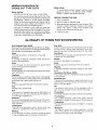
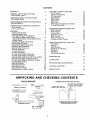
CONTENTS
WARRANTY
.............................
2
GENERAL SAFETY INSTRUCTIONS
FOR POWER TOOLS .....................
2
ADDITIONAL SAFETY INSTRUCTIONS
FOR TABLE SAWS .......................
3
MOTOR SPECIFICATIONS AND ELECTRICAL
REQUIREMENTS ........................
6
UNPACKING AND CHECKING CONTENTS
Tools Needed ...........................
List of Loose Parts ......................
....
7
7
8
ASSEMBLY ..............................
8
Installing Handwheels ....................
8
Adjusting Blade Insert ....................
9
Checking Heeling or Parallelism of
Saw Blade to Miter Gauge Groove .........
10
Adjusting Parallelism of Saw Blade to Miter
Gauge Groove .........................
10
Adjusting 90 Degree Bevel Stop ............
11
Adjusting Bevel Pointer ...................
12
Adjusting 45 Degree Bevel Stop ............
13
Installing Table Extensions ................
13
Aligning Table Extensions .................
14
To Raise Extension ......................
14
To Lower Extension ......................
15
Leveling Extensions .....................
15
To Lower Outer Edge of Extension ..........
15
To Raise Outer Edge of Extension ..........
15
Aligning Table Extensions with Front of Table . 16
To Move Outer Edge of Extension Back ......
16
To Move Outer Edge of Extension Forward ... 16
Installing Blade Guard ....................
17
Aligning Spreader .......................
18
Attaching Rip Fence .....................
19
Aligning Rip Fence ......................
20
Adjusting Miter Gauge ...................
20
Mounting Saw to Legs or Bench ............
20
UNPACKING
TOOLS
GETTING TO KNOW YOUR SAW ............
On-Off Switch ..........................
Elevation Handwheel .....................
Tilt Handwheel ..........................
Miter Gauge ............................
Blade Guard ...........................
Table Insert ............................
Rip Fence .............................
Removing and Installing Saw Blade .........
To Install Saw Blade .....................
21
21
22
22
22
22
22
22
22
23
BASIC SAW OPERATION USING THE
MITER GAUGE .........................
Work Helpers ...........................
Crosscutting
...........................
Repetitive Cutting .......................
Miter Cutting ...........................
Bevel Crosscutting ......................
Compound Miter Cutting ..................
24
24
25
26
26
27
27
BASIC SAW OPERATION USING THE
RIP FENCE ............................
Ripping ...............................
Bevel Ripping ..........................
Ploughing and Molding ...................
Resawing ..............................
Rabbeting .............................
Using Featherboards .....................
27
28
28
30
30
31
31
MAINTENANCE
32
LUBRICATION
..........................
............................
RECOMMENDED
33
ACCESSORIES
...........
TROUBLE SHOOTING .....................
35
REPAIR PARTS ...........................
36
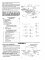
AND CHECKING
NEEDED
CONTENTS
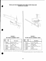
COMBINATION
SQUARE
MUST
STRAIGHT
3/4" THICK.
-'-J
Medium
_--
W renc-hes-
_-_
Screwdriver
7/16
in.
DRAW
BOARD
LIGHT
ALONG
LINE
THIS
ON
Screwdriver
Long
Nose
Pliers
BE TRUE.
EDGE
THIS
BE PERFECTLY
EDGE,
\
#2 Phillips
'_''T_
I Ll /-
\i,11
/
Combination
SHOULD
BE NO GAP
HERE
WHEN
SQUARE
OVER
IN DOTTED
Square
Hex "L" Wrench_es,
3/16", 1/8", 5/32"
34
OR OVERLAP
IS FLIPPED
POSITION,
OF BOARD
EDGE
MUST
STRAIGHT.
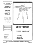
Model 113.221620 Table Saw with Table Extensions
is
shipped complete in one carton.
Separate all parts from packing materials and check
each one with the illustration
and the list of Loose
Parts to make certain all items are accounted
for,
before discarding
any packing
material.
If any parts are missing, do not attempt to assemble
the table saw, plug in the power cord or turn the
switch on until the missing
parts are obtained
and
are installed
correctly.
A
Apply a coat of automobile
wax to the table.
Wipe all parts thoroughly
with a clean, dry cloth.
WARNING:
FOR YOUR OWN
SAFETY,
NEVER
CONNECT
PLUG TO POWER SOURCE
OUTLET
UNTIL ALL ASSEMBLY
STEPS ARE COMPLETE,
AND YOU HAVE READ AND UNDERSTAND
THE
SAFETY AND OPERATIONAL
INSTRUCTIONS.
o___@
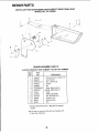
LIST OF LOOSE PARTS
DESCRIPTION
ITEM
A Guard Assembly .....................
B Extension Table L.H ..................
C Extension Table R.H ..................
D Handwheel .........................
E Rip Fence Assembly .................
F Miter Gauge Assembly ................
G Owners Manual .....................
QTY.
1
1
1
2
1
1
1
H
K
L
Loose Parts Bag No. 507545
(Containing the following items):
Wrench ......................................................
Bracket Spreader .......................................
Clamp, Spreader ........................................
N
O
P
Q
R
R
S
T
U
V
J
M
Loose Parts Bag No. 507546
(Containing the following items):
Washer, 17/64x9/16x3/64 .......................... 4
Screw, Pan Hd. 8-32x3/8 ........................... 2
Nut, Sq. 1/4-20 ...........................................
2
Screw, Soc. Set 1/4-20x7/8 ....................... 2
Lockwasher, Ext. 1/4 ................................. 4
Lockwasher, Ext. #8 .................................. 2
Nut, Hex 1/4-20 ..........................................
2
Screw, Truss Hd. 1/4-20x5/8 ..................... 2
Screw, Flat Hd. 1/4-20x5/8 ...................... 14
Key Switch .................................................
1
Support Spreader ......................................
1
Nut, Wing 1/4-20 ........................................
2
N
2
1
1
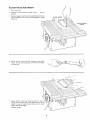
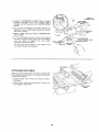
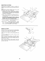
ASSEMBLY
INSTALLING
1. From among
Iockwashers
screws.
HANDWHEELS
REMOVE
CARDBOARD
FROM
UNDERNEATH
MOTOR
the loose parts find two #8 external
and two 8-32 x 3/8 inch long Phillips
2. Install elevation
handwheel
onto elevation
shaft
by lining up FLAT SPOT on shaft with flat inside
handwheel.
Install screw and Iockwasher.
3. Install
bevel
handwheel
onto
bevel shaft
by
lining
up FLAT SPOT on shaft with flat inside
handwheel.
Install screw and Iockwasher.
WARNING:
Failure to complete
the following
two
steps could result in damage to your saw.
4. Turn elevation
handwheel
counter-clockwise
to
pull motor away from inner packing cardboard.
5. Remove
cardboard.
LOCKWASHER
SCREW
/
SCREW
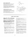
ADJUSTING
1. Turn
BLADE
INSERT
saw over.
2. Loosen
remove.
Phillips
screw
in blade
insert..,
do not
3. Remove blade insert by lifting slightly and pulling
insert toward front of saw to disengage
from key
hole slot.
BLADE
INSERT
\
PHILLIPS
HEAD
SCREW
4. Tab at rear of insert should
firmly.
It may be necessary
using pliers.
5. Install
insert
insert
under
Tighten
engage in saw table
to bend tab slightly
blade insert
by placing
keyhole
slot in
over screw head in saw table and pushing
to rear of saw table sliding
tab in insert
saw table ledge.
screw.
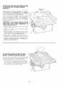
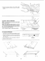
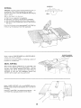
CHECKING
HEELING
OR PARALLELISM
OF SAW BLADE
TO MITER
GAUGE
GROOVE
MARK
'X' ON
TOOTH
While cutting,
the material
must move in a straight
line PARALLEL
to the SAW BLADE
. . . therefore
both the miter gauge GROOVE and the RIP FENCE
must be PARALLEL
to the SAW BLADE.
If the saw blade is not parallel
to the miter gauge
groove, it is said to have "HEEL". This condition
can
cause the workpiece
to bind or move workpiece
away from the rip fence at the end of a cut, possibly
causing
a kickback.
WARNING:
TO
AVOID
ACCIDENTAL
START
MAKE
"OFF"
AND
PLUG
IS NOT
POWER SOURCE
OUTLET.
INJURY
FROM
SURE SWITCH
IS
CONNECTED
TO
1. Elevate
blade
to maximum
elevation
handwheel.
height
2. Mark an "X" on one
(bent) to the LEFT.
of the teeth
by
which
\
turning
is SET
3. Place the head of a combination
square in the
MITER GROOVE. Adjust blade of square so that it
just touches
the tip of the MARKED
tooth.
4. Move square
to REAR, rotate
blade to see if
MARKED
tooth again touches
blade of square.
5. If tooth
touches
square
the
FRONT
and REAR, sawblade
MITER GAUGE
GROOVE.
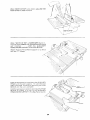
ADJUSTING
BLADE TO
PARALLELISM
MITER
GAUGE
same amount
is PARALLEL
at
to
OF SAW
GROOVE
If tooth
does
not
touch
front
and
rear the
mechanism
underneath
must be adjusted
to make
the blade PARALLEL
to miter gauge groove.
1. Loosen the four hex socket screws in the top of
the table next to the saw blade using a 3/16 inch
hex L wrench.
This will allow the mechanism
below the table to be shifted sideways.
10
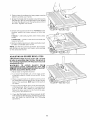
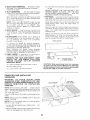
2.Folda pieceof cardboardor heavypaperoverthe
bladeto protectyour hands.
3. Graspthe bladeandthecradlerodandmovethe
mechanismrightor leftasmallamountasneeded
to makethe squaretouchthesameamountfront
and rear.Tightenonescrew.
4. Checkwithsquaretodetermineif MARKED
tooth
touchessquarethe sameamountat front and
rear.
If it does-- alternatelytightenotherthreescrews
slowly.
If it doesnot-- loosenscrewandmovebladethe
requiredamount.
5. Recheckbladeclearanceto tableandtableinsert
to makesurebladedoesnot hit.
NOTE:Usethe hexL wrenchasshown.Donotusea
pairof pliersor anyothertoolto gainmoreleverage
on the setscrewwrench.
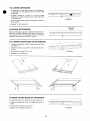
ADJUSTING
90 DEGREE
BEVEL
STOP
(IMPORTANT:
Blade must be square (90 ° ) to table
in order to accurately align the saw. Using care in
the following adjustments will help assure accurate
woodworking
cuts.)
WARNING:
TO
AVOID
INJURY
FROM
ACCIDENTAL
START, TURN SWITCH "OFF" AND
REMOVE
PLUG FROM POWER SOURCE
OUTLET
BEFORE ADJUSTING
BEVEL STOP.
1. Raise
blade
to highest
elevation.
2. Turn bevel handwheel
just until it stops under
moderate
pressure.
Blade should be 90 ° to the
table top.
3. Place a square flush on the table top to the left of
the sawblade and slide the square up against the
body of the sawblade.
NOT against the teeth of
the blade.
4. The square should be nearly flush with the body
of the sawblade.
When this isso, the sawblade
is
said to be 90 ° with respect
to the table top.
Notice the bevel pointer on the front of the saw.
The pointer should be at 0°.
5. If you feel the blade is not close enough
to 90 °
with respect to the table top, further adjustment
can
be made
by performing
the following
operations.
!i
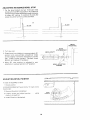
ADJUSTING
90 DEGREE
BEVEL
STOP
1. On the stop bracket
are two 10-32 pan head
screws which set 90 ° stop position.
If condition
A
exists the two screws need to be turned clockwise
to obtain 90 ° setting.
If condition
B exists the
srews should be turned counterclockwise.
/
I
A
IBLADE
/
B
/BLADE
[
Ii
Ii
II
It
!1
tl
LL
II
I/
LI
BEVEL
HANDWHEEL
2. Turn
1
BEVEL
STOP BRACKET I
saw over.
BEVELSHAFT
3. Rotate bevel crank blade is in approximately
40 °
position
and using phillips
screwdriver
rotate
screws slightly
in direction
necessary
to correct
gap, (rotate
screws
equally).
Recheck
blade
position
and readjust if necessary.
4. When
90 ° stop position
is adjusted
to
satisfaction
re-adjust
pointer to 0° position.
X
J
J
your
BEVEL
ADJUSTING
SCREWS
ADJUSTING
If blade
BEVEL
IS SQUARE
1. Check
to table:
pointer.
If POINTER
bevel scale:
DOES
NOT
2. Remove
Elevation
3. Loosen
medium
screw
and
screwdriver.
4. Install
"----I
POINTER
Elevation
point
to the"0"
mark on the
/
Handwheel.
adjust
/
pointer
BEVEL
POINTER
. . . using
Handwheel.
/
t
12
/
/
\
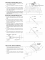
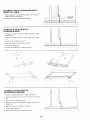
CHECKING
45 DEGREE
BEVEL
!. Turn elevation
handwheel
blade as high as it will go.
2. Turn bevel
45 ° '
handwheel
STOP
clockwise
clockwise
to
raise
to tilt blade
to
3. Lay head of combination
square on the blade of
square as illustrated
and place head against the
blade• Make sure square is not touching
TIP of
one of the saw TEETH.
4. The 45 ° blade stop is set during manufacturing•
If adjustment
is needed proceed
to next step. If
bevel adjustment
is satisfactory
go on to installing
table extensions•
ADJUSTING
45 DEGREE
BEVEL
r
STOP
\
1. The 45 ° blade
position
is controlled
by the
location
of the sheet metal nut on end of bevel
shaft•
45
ANGLE
A
|LADE
2. If condition
A exists the sheet metal nut needs to
be turned clockwise
(CW) to obtain 45 ° setting• If
condition
B exists the nut should
be turned
counterclockwise
(CCW).
\\
\',,.,
\\
\\
3. To correct
condition
A - Rotate
bevel handle
CCW approximately
2 turns, place 11/16 inch
wrench
on sheet metal nut and hold in place
while rotating
handle counterclockwise
in small
increments.
Recheck
blade position
after each
rotation.
/\\
/
45
4. To correct condition
B- Same procedure
as No.
3, except, rotate handle clockwise
while holding
nut.
5. Check blade clearance
by rotating
making sure blade does not strike
\\
/
ANGLE
blade by hand
insert or table•
\x
x\
N\
SHEET METAL
NUT
BEVEL LINK
_/
WASHER
_ [_
\\
i
\\\
BEVEL SHAFT
FLAT HEAD
HEX SOCKET
SCREWS
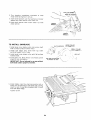
INSTALLING
TABLE
EXTENSIONS
1. Among
loose parts locate fourteen
1/4-20
inch long flat head hex socket screws.
x 5/8
2. Install
right table extension
and install seven
screws using a5/32 inch hex Lwrench.
Just start
screws.
I
3. Install
left table extension
and install
seven
screws using a5/32inch
hex Lwrench.
Just start
screws.
13
3. Install left table extensionand install seven
screwsusing5/32inch hexL wrench•Juststart
screws.
L
ALIGNING
TABLE
EXTENSIONS
NOTE: The table extensions must be the same height
as the table and level.
NOTE: When aligning the table extensions, the 1/4-20
x 5/8 inch flat head hex socket screws may "bottomout". If this occurs simply loosen the screws and restart
the process for proper alignment.
Place combination
square on table and extension.
_
TO
RAISE
BE SAME HEIGHT
EXTEN_SION
SHOULD
AS TABLE
EXTENSION
1• If extension
is low loosen three screws on top of
the table extension
A, B, and C. See illustration•
,i_j,;t__3!,,,l
r i _ i i 1,_,1 _ ; i,I
2• Tighten
screws D, E, F, and G underneath
table
extension
to raise extension
even with table top
front and rear.
3. Check
height
4. Repeat
with square
and tighten
A, Band
C.
EXTENSION
for left extension.
\•
G
F
! E
,,D
14
E
'
I,_ 1,_,]
TO
1.
2.
LOWER
EXTENSION
If extension
is too high loosen four screws on
underside
of the extension
D, E, F, and G. See
illustration.
Tighten
screws
A, B and
extension
to lower extension
front and rear.
3. Check height
E, F and G.
4. Repeat
with square
,1 ,L,l,l,l,_,l,l,l,l,[,I,l,i,l,l,l,l,l,l,l,l,l,l,l,l,l,I,]
--L_r
C on top of table
even with table top
1
EXTENSION
and tighten
screws
D,
for left extension.
SHOULD
LEVELING
,i,_,i,l,l,l,i,L,l,,,I,L,l,J,i,l,i,J_,J,i,l,f,_,l,l,l,i,
Place combination
square on table and extension
so
that end of blade extends over edge of extension.
Hold square firmly on saw table and check for gap
between
extension
and blade of square.
TO
LOWER
OUTER
1. Loosen screws
illustration.
2. Tighten
is level.
3. Snug
screws
down
4. Repeat
EDGE
OF EXTENSION
B, E, and Fon right extension.
C, D, and G until
screws
See
table extension
B, E, and F.
EXTENSION
for left extension.
\\\\
£
TO
RAISE
OUTER
EDGE
D\
OF EXTENSION
!. Loosen
screws
C, D, and G on right
2. Tighten
level.
screws
B, E, and F until table extension
3. Snug
4. Repeat
down
screws
for left table
BE
NO GAP
EXTENSIONS
extension.
is
1
C, D, and G.
extension.
EXTENSION
15
ALIGNING
TABLE
FRONT
OF TABLE
EXTENSIONS
1. Place blade of combination
table and table extension.
2. Extension
should
line
square
WITH
on
front
of
, ;I
!
up with
;iij
table.
J"
SHOULD
BE
NO GAP
/
//
TO MOVE
EXTENSION
OUTER
EDGE
BACK
OF
I
1. Loosen screws
illustration.
C and
2, Tighten
up.
B and G until
3. Snug
down
screws
5. Check
left extension.
6. Adjust
left extension
/
•
©
'l'['l'l'_
manner.
!,
\"
"'x
.
•\
F
OUTER
EDGE
FORWARD
screws
screws
OF
B and G in right
C and
3. Snug down screws
4. Recheck
level and
extension.
F until
extension.
extension
B and G.
flatness
to table.
is lined
Check
©
left
i L
4. Recheck
'i'l'!'r,!,r,l,f,l,l,lrr,l,l,!,l,l,l,j,_,l,
F
TO MOVE
EXTENSION
1. Loosen
is lined
to table.
in same
S
G
2. Tighten
up.
extension
--_JJ--
, '",,
•
See
C and F,
level and flatness
J
extension,
]
screws
4. Recheck
F in right
level and flatness
5. Check
left extension.
6. Adjust
left extension
......
to table•
in same
rf:r'_'1'i'!'l'i'i'l'l_
manner.
16
I'
"i
I'l'_'i_Pi'i'lr_'l'l'['_'l'_'J
G
SQUARE
NUT
-_
SUPPORTs..
(_/
TRUSS
HEAD
SCREW
INSTALLING
BLADE
5/8
GUARD
IN. LONG
SOCKET
1. From among
shown.
the loose parts, find the hardware
as
_
_
"-_--_
SPREADER
_._-_-----__ _//
HEAD
_-°-
SETSCREW
7/8
SPREADER
_
_
_
--8
HEX NUT
SPREADER
CLAMP
_V///
_fa
IN. LONG
BRACKET
It-
I
""['_-_
t-_
WING
NUT
"1_
LOCKWASHER
EXT. 1/4 IN.
BLADE
WITH
SQUARE
TABLE
/
2 MAKE SURE THE BLADE
AND SQUARE
WITH THE
IS ALL THE WAY
TABLE.
3. Position
SPREADER
SUPPORT
even with the end of the rod.
on rod until
UP
it is
\ SPREADER
SUPPORT
EVEN WITH ROD
\',\
;
_
SQUARE
NUT
4. Assemble
the 7/8 in. long
setscrews,
nuts,
Iockwashers
and washers
to the SPREADER
SUPPORT
BRACKET
and slip the nuts into the
slot in the spreader
support.
5. Finger
tighten
ONLY
THE HEX NUTS.
• -____
,-
17
L
SETSCREW
i
/
,.oc,,w,s.ER
6. Laya pieceof flatstraightwoodanda squareon
sawtableandrotatethe SPREADER
SUPPORT
until the bracketis alignedwith square.
7. MAKESURE END OF SUPPORT,BRACKET
ANDRODAREEVEN... usingan 1/8in, HexL
wrench,TIGHTENTHESETSCREWSONLY.
ENDS
OF SUPPORT
AND BRACKET
TO
BE EVEN WITH
END OF ROD
/
TIGHTEN
SETSCREW
ONLY
!SPACE
EQUAL
3 THICKNESSES
ALIGNING
APPROX.
OF PAPER
KERF
WOOD
i
SPREADER
IMPORTANT:
The SPREADER
must always
PARALLEL
to the sawblade and in the MIDDLE
the cut (KERF) made by the sawblade,
TO
be
of
BLADE
/
!lllll
I
SPREADER
NOTE: T_qe spreader
is thinner than the width of the
KERF by approximately
six thicknesses
of paper
SPACE
EQUAL
3 THICKNESSES
1. Make two folds
in a small piece (6 x 6 in.) of
ordinary
NEWSPAPER
making
three
thicknesses.
The folded
paper will be used as a
"spacing
gauge".
18
TO APPROX.
OF PAPER
LOOKING
DOWN
ON
SAW
PIECE
STRAIGHT
2. Installthe SPREADER
CLAMP.Placespreader
between spreaderclamp and bracket. Move
forwarduntilallthreeareinline.TIGHTENWING
NUTS.
3. Lay a piece of straight flat wood againstthe
sawblade.Insertfoldedpaperbetweenspreader
andstrip of wood.
4. MAKE SURETHE HEX NUTS UNDERNEATH
ARELOOSE•
5. Lift the antikickbackpawlto clearthe woodand
hold the spreadertightlyagainstthewood.Make
sure the wood is against the saw blade. THREE
TIGHTENTHEHEXNUTS.
This will alignthe spreaderin the middleof the
cut (KERF)madeby sawblade.
TIGHTLY
AGAINST
HOLD
WOOD
BLADE
WOOD
t
ANTIKICKBACK
PAWLS
HOLD
TIGHTLY
SPREADER
THICKNESSES
OF
PAPER
WING
SPREADER
AGAINST
WOOD
BRACKET
SPREADER
NOT
CLAMP
RIP FENCE
ATTACHING
RIP
FENCE
Apply a coat of paste wax to the top surface and
front ledge of the saw table. This will allow the fence
to slide more easily•
1. Loosen
fence
clockwise.
lock
knob
2, Attach fence head by placing
front ledge in saw table.
by
turning
head
counter-
of fence
over
FENCE LOCK
KNOB
19
OF
MUST
LINE UP WITH
SLOT FRONT
AND
ALIGNING
RIP
FENCE
IMPORTANT:
saw blade and
KICKBACK
of
adjustment
is
The rip fence MUST be parallel with
miter grooves in order to help prevent
the workpiece when ripping. Careful
required.
MITER
REAR
1. Hold head of rip fence and slide on table until the
edge of the fence lines up with the right miter slot.
2. Turn fence lock knob clockwise
to lock fence.
3. If fence
rear:
does
A. Loosen
not line up with
the two
miter
hex screws
ADJUSTING
MITER
and
HEAD
in top of fence.
B. While holding
head of rip fence,
rip fence right or left until edge
miter slot.
C. Tighten
hex screws
not to move fence.
slot front
alternately
LOOSEN
SCREWS
move rear of
lines up with
being
TWO HEX
TO ADJUST
careful
GAUGE
NOTE: The graduations
are manufactured
to very
close tolerances
which
provide
suitable
accuracy
for average
woodworking.
In some cases where
extreme
accuracy
is required,
when making
angle
cuts, for example, make a trial cut and then recheck
it.
tf necessary,
the miter gauge
swiveled
slightly
to compensate
The HEAD should
be SQUARE
when the pointer
points to "0".
head can then be
and then locked.
(90 ° ) with the bar
BAR
To check for squareness,
place an accurate
square
on the miter gauge. If the head is NOT SQUARE with
the bar:
1. Loosen
the lock
handle.
2. Position
the head square
the handle.
3. Loosen
the screw
points to zero.
and
with the bar..,
adjust
the
pointer,
tighten
so it
12-3/4
REAR OF SAW
t
[
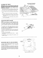
MOUNTING
SAW
TO
LEGS
OR
4 HOLES
.312 DIA.
BENCH
t!
OPENING
_
:
\
I
I
\\
If you purchase
Craftsman
Steel Legs for your saw,
assemble
them
according
to
the
directions
furnished
with them.
\
\
\,
10-7/8
11-7/8
If you mount the saw on any other bench, make sure
that there is an opening
in the top of the bench the
same size as the opening
in the bottom of the saw so
that the sawdust can drop through.
Recommended
working
height is 33 to 37 in. from the top of the saw
table to the floor.
,
//7
z- 10-3
.
1
11-3/16
NOTE:
2O
All dimensions
in inches.
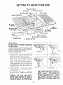
GETTING
TO KNOW YOUR SAW
5 BLADE
GUARD
6
SPREADER
8 SAWBLADE\ %
4
MITER
MITER
LOCK
\ ......
TABLE
INSERT
l/7
R,PFENCE
\\\\
GUAGE
KN
EXTENSION
TI
2 ELEVATION
HANDWHEEL
POWER
CORD
1. ON-OFF
SWITCH
CAUTION:
Before turning switch
the
blade
guard
is correctly
operating properly.
1 ON-OFF
SWITCH
on, make sure
installed
and
The On-Off
Switch
has a locking
feature. THIS
FEATURE
IS INTENDED
TO HELP PREVENT
UNAUTHORIZED
AND POSSIBLE HAZARDOUS
USE BY CHILDREN
AND OTHERS.
A. Insert
Key into
INSERT
KEY
switch.
B. TO turn saw ON...
stand to either side of the
blade never in line with it... insert finger under
switch lever and pull END of lever out.
After
blade
turning
to come
switch
ON, always
allow the
up to full speed before cutting.
Do not cycle the motor switch
on and off
rapidly,
as this may cause the sawblade
to
loosen.
In the event this should ever occur,
allow the sawblade
to come to a complete
stop
and retighten
the arbor
nut normally,
not
excessively.
Never leave the saw while the
power is "ON".
TURN
C. TO turn saw OFF . . . PUSH lever in. Never
leave the saw until the cutting tool has come to
a complete
stop.
D. To lock switch in OFF position..,
IN with one hand...
REMOVE
hand.
OFF
REMOVE
KEY
"OFF".
WHEN
SAW IS NOT
IN USE...
REMOVE
KEY AND KEEP IT IN A SAFE
PLACE . . . ALSO . . . IN THE EVENT OF A
POWER FAILURE
(ALL OF YOUR LIGHTS
GO OUT) TURN SWITCH
OFF . . . LOCK IT
AND
REMOVE
THE
KEY.
THIS
WILL
PREVENT
THE SAW FROM STARTING
UP
AGAIN
WHEN THE POWER COMES BACK
ON.
hold switch
key with other
WARNING:
FOR
YOUR
OWN
SAFETY,
LOWER BLADE OR OTHER CUTTING
TOOL
BELOW
TABLE
SURFACE.
(IF BLADE
IS
TILTED,
RETURN
IT TO VERTICAL
(90 ° )
POSITION).
ALWAYS
LOCK THE SWITCH
21
2. ELEVATION
HANDWHEEL...elevates
the blade.
clockwise
or lowers
to elevate •..
Turn counterclockwise
to lower•
D. Lift insert
of saw.
7o
NOTE: There are LIMIT STOPS inside the saw
which prevent the blade from tilting
beyond 45 °
to the LEFT
and 90 ° to the RIGHT.
(See
"Adjustments"
section "Blade Tilt, or Squareness
of Blade to Table").
RIP FENCE...
is locked in place by tightening
the
lock knob. To move the fence, loosen the knob
and grasp the fence with one hand at the front.
Holes are provided
in the rip fence for attaching
wood
facing
when
using the dado
head.
molding
head.
Attach
it to the fence with two Round Head #10
Wood Screws 2 in. long. To remove the facing,
loosen the screws, slide the facing forward
and
pull the screws through
the round holes.
5. BLADEGUARD
must always
be in place and
working
properly
for all thru-sawing
cuts. That is,
alt cuts
whereby
the blade
cuts
completely
through
the workpiece.
WOOD
To remove
the guard
for special
operation,
loosen
both wing nuts, slide spreader
back and
up DO NOT DISTURB
THE SETTING
OF THE
SPREADER
SUPPORT
BRACKET.
When
replacing
the
guard,
insert
spreader
between
bracket
and clamp and slide forward.
TIGHTEN
BOTH WINGNUTS
SECURELY.
the blade
B. Raise
blade
C. Loosen
REMOVING
SAWBLADE
below
the table
"\
\
\,
_._
or
X
'----ROUNO
HEAD
10 WOOD
AND
(Do
Not Remove)
INSTALLING
WARNING:
TO
AVOID
INJURY
FROM
ACCIDENTAL
START, TURN SWITCH
"OFF" AND
REMOVE PLUG FROM POWER SOURCE
OUTLET
BEFORE
REMOVING
OR
INSTALLING
SAWBLADE.
BLADE
NOTE: When installing
the blade..,
make sure the
upper saw teeth are pointing
toward the front of the
saw..,
and that the blade and collars are clean, and
free from any burrs.
The HOLLOW
blade.
side of the collars
NOTE:
before
Always place
the blade.
NOTE:
wrench
Do not overtighten
to just "snug" it.
1. Loosen Phillips
not remove.
SCREWS
CAUTION:
When positioning
fence for maximum
rip, make sure end of fence HEAD is even with edge
of table extension.
Fence cannot be locked securely
beyond the edge of the table extension.
surface.
guard.
Screw.
FACING
,\
WARNING:
FOR YOUR OWN SAFETY,
TURN
SWITCH
"OFF"
AND REMOVE
PLUG
FROM
POWER
SOURCE
OUTLET
BEFORE
REMOVING
INSERT.
A. Lower
must be against
the LARGE
arbor
head screw
collar
the
on the shaft
nut. Use the arbor
in blade insert...
a
or
Select a piece of smooth straight
wood approx.
3/4" thick, at least as long as the rip fence, and at
least 7-1/2"
wide (high) to permit
clamping
of
featherboards.
4. MITER GAUGE...
head is locked in position
for
crosscutting
or mitedng
by tightening
the lock
knob
ALWAYS
LOCK IT SECURELY
WHEN IN
USE
is removable
for removing
or other cutting
tools . . .
front
NEVER
OPERATE
THE SAW WITHOUT
THE
PROPER
INSERT
IN PLACE.
USE THE SAW
BLADE
INSERT WHEN SAWING
. . . USE THE
MOLDING
INSERT WHEN MOLDING.
3. TILT HANDWHEEL
. . . tilts the blade for bevel
cutting• Turn counterclockwise
to tilt toward left.
• . clockwise
to tilt toward right•
When the blade is tilted to the LEFT as far as it will
go, it should be at 45 ° to the table and the bevel
pointer
should point 45 ° .
6. TABLE
INSERT
installing
blades
from front end, and pull toward
Do
2. Remove blade insert by lifting slightly and pulling
insert to disengage
from key hole slot.
22
INSERT
PHILLIPS
HEAD
SCREW
3. Turn elevation
handwheel
clockwise
motor shaft as high as it will go.
to
4. Insert shaft wrench
over
spacer and arbor wrench
flat portions
of motor
over arbor nut.
5. Hold
arbor
loosen
shaft wrench
wrench.
and
arbor
nut
PULL
LOOSEN/_
TO TO TIGHTEN
PUSH
raise
with
ARBOR
WR
/
/
ARBOR
WRENCH
/' / //!
TO INSTALL
SAWBLADE
1, Install large inner blade collar onto
with rounded
surface toward motor.
2. Install
saw blade
onto
shaft
pointing
toward front of saw.
3. Install small outer
toward blade.
blade
collar
with
with
motor
FLAT
shaft
/
//-
top
flat
/
teeth
jl_.J_
_
'_ 4-
*
SMALL
COLLAR
_ (1-3_4"
DIAMETER}
surface
'
j:
4. Install arbor nut. Note: Arbor nut should just be
snug. Do not overtighten.
TOPTEETH
TO FRONT
IMPORTANT: Do not attempt to run saw without
both blade collars properly installed.
5. Install
blade insert
by placing
keyhole
slot in
insert over screw head in saw table and pushing
insert to rear of saw table engaging
tab in insert
onto saw table ledge.
Tighten
LARGE
COLLAR
(2" DIAMETER)
SURFACES
screw.
23
POINTING
OF SAW
HEX
....
_
_,
t..
<*'_-_:_
NU'f
BASIC
USING
SAW OPERATION
THE
MITER
by the back of the blade and thrown toward the
operator).
Stand to either side of the blade.
CROSSCUTTING,
MITER
CUTTING,
BEVEL
CUTTING,
COMPOUND
MITER
CUTTING
and
when RABBETING
across
the end of a narrow
workpiece,
the MITER GAUGE
is used.
7.
WARNING:
FOR YOUR OWN SAFETY,
ALWAYS
OBSERVE
THE
FOLLOWING
SAFETY
PRECAUTIONS
IN ADDITION
TO THE SAFETY
INSTRUCTIONS
ON PAGES 2, 3, and 4.
lock
the
miter
gauge
securely
when
rip fence
from
stalls
OFF
of the blade
and out of
or stops while
cutting,
TURN
before
attempting
to free the
9. Do not reach over or behind the blade to pull the
workpiecethrough
the cut...tosupportlong
or
heavy workpieces..,
to remove cut-off pieces of
material
or FOR ANY OTHER
REASON.
10. Do not pick up small pieces of cut-off
material
from the table. REMOVE them by pushing them
OFF the table with a tong stick. Otherwise
they
could be thrown back at you by the rear of the
blade.
in
use.
3. Remove
Keep your hands clear
the path of the blade.
8. If blade
SWITCH
blade.
1. Never make these cuts freehand
(without using
the miter
gauge
or other
auxiliary
devices)
because
the blade could bind in the cut and
cause a KICKBACK
or cause your fingers
or
hand to slip into the blade.
2. Always
GAUGE
table.
11. Do not remove small pieces of cut-off material
that may become
TRAPPED
inside the blade
guard while the saw in RUNNING.
THIS COULD
ENDANGER
YOUR
HANDS
or
cause
a
KICKBACK.
4. Make sure blade guard is installed
for all "thrusawing"
operations
(when
sawblade
cuts
entirely
thru the thickness
of the workpiece.)
Replace guard IMMEDIATELY
after completion
of dadoing,
molding or rabbeting
cuts.
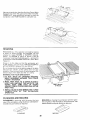
Turn the saw OFF. After the blade
turning,
lift the guard and remove
5. Have blade extend approximately
1/8 in. above
top of workpiece.
Additional
blade exposure
would increase the hazard potential.
12. If workpiece
is warped,
place
side DOWN. This will prevent
while it is being cut.
6. Do not stand directly in front of the blade in case
of a THROWBACK
(Small cut-off
piece caught
has stopped
the piece.
the CONCAVE
it from rocking
SLIGHTLY
THICKNESS
LESS THAN
OF WORKPIECE
UP TO 3/8"
3/4
WORK
HELPERS
J'_'_
Before cutting
any wood on your
the "Basic Saw Operations".
saw, study
1-5/8
all of
li
'l
Notice that in order to make some of the cuts, it is
necessary
to use certain
devices
"Work Helpers"
like the Push Stick, the Push Block and the Auxiliary
Fence, which you can make yourself.
_I
15 __-
After you have made a few practice
cuts, make up
these "helpers"
before starting
any projects.
Make
the "Push Stick" first. To rip the piece for the push
stick, start out with a wide board, say 11-1/2in.wide
and set the rip fence 9-3/4 in. from the blade.
NOTE:
"
*_" _ ,_/
All dimensions
PUSH
THESE
EDGES
MUST
BE PARALLEL
t--1/2
NOTCH
in inches
STICK
-....
3/4 PLYWOOD
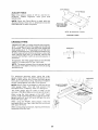
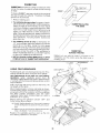
PUSH STICK AND PUSH BLOCK
Make the Push Stick using a piece of 1 x 2.
Make the Push Block using a piece of 3/8 in. and 3/4
in. plywood.
The small piece of wood 3/8 in. x 3/8 in. x 2-1/2 in.
should be GLUED to the plywood...
DO NOT USE
NAILS. This is to prevent dulling the sawblade in the
event you mistakingly cut into the push block.
Position the handle in the center of the plywood and
fasten together with glue and woodscrews.
NOTE:
24
All dimensions
in inches
3/8 PLYWOOD
3/8 PLYWOOD
AUXILIARYFENCE
/
3/4
Make one using a piece of
plywood.
Fasten
together
woodscrews.
3/8 in.
with
PLYWOOD
and 3/4 in.
glue
and
NOTE:
Since the Push Block
is used
Auxiliary
Fence, the 4-3/4 in. dimensions
held identical
on both the pieces.
1-1/8
with the
must be
THIS FACE AND
THIS EDGE MUST
BE PARALLEL
_" 14
"t.
,d'
I
"_.
r
NOTE: All dimensions in inches.
AUXILIARY
FENCE
CROSSCUTTING
CROSSCUTTING
is cutting wood across the grain,
at 90 °, or square with both the edge and the flat side
of the wood. This is done with the miter gauge and
blade angle set at"0". The graduations
on the miter
gauge provide accuracy
for average woodworking.
In some cases where extreme accuracy
is required,
when making angle cuts, for example,
make a trial
cut and then recheck
it with an accurate
square, or
protractor.
If necessary,
the miter
slightly
to compensate
WORKPIECE
I
i
I
Jtt
_-----
TABLE
gauge head can be swiveled
for any inaccuracy.
NOTE: The space between the miter gauge
the groove in the table is held to a minimum
manufacturing.
bar and
during
For maximum
accuracy
when
using
the miter
gauge, always "favor" one side of the groove in the
table. In other words, don't move the miter gauge
from side to side while cutting,
but keep one side of
the bar riding against one side of the groove.
SANDPAPER
\
NOTE: Glue a piece of sandpaper
to the face of the
miter
gauge
head.
This will
help prevent
the
workpiece
from "creeping"
while it is being cut.
PLYWOOD
CLAMPED
TO SAWHORSE
i
The miter
gauge
may be used in either of the
grooves in the table. Make sure locking
knob is tight.
When
using the miter
gauge
in the LEFT hand
groove, hold the workpiece
firmly against the miter
gauge head with your left hand, and grip the lock
knob with your right.
When
using the RIGHT
workpiece
with your right
with your left hand.
hand
hand
When cutting long workpieces,
supported
from the floor.
LINE
groove,
hold the
and the lock knob
make suretheend
is
25
FOR
CLARITY
REPETITIVE
CUTTING
REPETITIVE
CUTTING
is cutting
a quantity
of
pieces the same length without having to mark each
piece.
NOTE:
When making
workpiece
make sure
repetitive
cuts
it is supported.
from
a long
1. NEVER USE THE RIP FENCE AS A LENGTH
STOP BECAUSE
THE CUTOFF
PIECE COULD
BIND BETWEEN
THE FENCE AND THE BLADE
CAUSING
A KICKBACK.
2. When wnaking repetitive
cuts shorter
than 6 in.,
clamp a block of wood 3 in. long to the table to act
as a !ength stop.
CAUTION:
When clamping
the block, make sure
that the end of the block is well in front of the
sawblade.
Be sure it is clamped
securely.
3. Slic_e the workpiece
touches
[he block
along the miter gauge
. . . hold it securely.
until
it
4. Make the cut..,
pull the workpiece
back..,
push
the cut off piece off the table with a long push
stick .
DO NOT ATTEMPT
TO PICK IT UP AS
THIS COULD
ENDANGER
YOUR HANDS.
MITER
CUTTING
TABLE
MITER CUTTING
is cutting
wood at an angle other
than 90 ° with the edge of the wood. Follow the same
procedure
as you would for crosscutting.
Adjust
the
lock it.
miter
gauge
The miter
gauge
may
grooves
in the table.
to the desired
angle,
and
TOP
be
used
in either
of the
When
using the miter gauge
in the LEFT hand
groove,
hold the workpiece
firmly against the miter
gauge head with your left hand, and grip the lock
knob with your right.
When
using the RIGHT
workpiece
with your right
with your left hand.
hand
hand
groove,
hold the
and the lock knob
26
VIEW
WORKPIECE
BEVEL
CROSSCUTTING
BEVEL CROSSCUTTING
is the same as crosscutting except that the wood is cut at an angle...
other than 90 ° with the fiat side of the wood.
Adjust
the blade
to the desired
angle.
Use the Miter Gauge in the groove to the RIGHT of
the blade. It cannot
be used in the groove to the
LEFT because the blade guard will interfere.
Hold
the workpiece
with your right hand and the lock
knob with your left hand.
COMPOUND
MITER
CUTTING
COMPOUND
MITER CUTTING
is a combination
of
miter cutting
and bevel crosscutting.
The cut is
made at an angle other than 90 ° to both the edge
and the flat side of the wood.
i
!
jJ
Adjust the miter gauge and the blade to the desired
angle ... Make sure miter gauge is locked.
USING
THE
RIP FENCE
RIPPING,
BEVEL
RIPPING,
RESAWING
AND
RABBETING
are performed
using the RIP FENCE
together
with
the
AUXILIARY
FENCE!WORK
SUPPORT,
PUSH STICK OR PUSH BLOCK.
5. Have blade extend approximately
i"_ in. _r,ove
top of workpiece.
Addttiona!
b!_de exf:csc;re
would
increase the hazard poter_tial
WARNING:
FOR YOUR OWN SAFETY,
ALWAYS
OBSERVE
THE
FOLLOWING
SAFETY
PRECAUTIONS
IN ADDITION
TO THE SAFETY
INSTRUCTIONS
ON PAGES 2, 3 and 4.
7. Keep your hands clear
the path of the blade.
6. Do not stand directly in front ofthe blade in case
of a KICKBACK.
Stand to either side of the
blade
3. Remove
lock the rip fence
miter
gauge
from
securely
when
9.
in use.
table.
Do not reach over or behind the blade to pull the
workpiece
through
the cut..,
to support
long or
heavy workpieces
. . to remove small cut-off
pieces
of material
or FOR
ANY
OTHER
REASONS.
10. Do not pick up smal
pieces of cut-off material
from the table. REMOVE them by pushing them
OFF the table with a long stick. Otherwise
they
could be thrown
back at you by the rear of the
blade.
4. Make sure blade guard is installed
for all thrusawing
type
cuts.
Replace
the
guard
IMMEDIATELY
following
completion
of
resawing,
rabbeting,
dadoing,
or
molding
operations.
Frequently
check
the
action
of
ANTIKICKBACK
PAWLS
by
passing
workpiece
alongside
of the spreader
while
is OFF.
and out of
8. If the blade stalls or stops while cutting,
TURN
SWITCH
OFF before
attempting
to free the
blade.
1. Never make these cuts FREEHAND
(without
using the rip fence or auxiliary
devices when
required)
because
the blade could bind in the
cut and cause a KICKBACK.
2. Always
of the blade
11. Do not remove small pieces of cut-off
material
that may become
TRAPPED
inside the blade
guard while the saw is RUNNING.
THIS COULD
ENDANGER
YOUR
HANDS
or
cause
a
KICKBACK.
the
the
saw
Turn the saw OFF. After the blade
turning,
lift the guard and remove
Pull the workpiece
TOWARD
you. If the PAWLS
do not DIG into the workpiece
and _tOLDit...
the
pawls
must
be
REPLACED
OR
SI4ARPENED.
See "Maintenance"
section.
12. If workpiece
side DOWN.
rocking
while
27
is warped,
This will
it is being
has stopped
the piece.
place the CONCAVE
help prevent
it from
ripped.
WORKPIECE
RIPPING
RIPPING
is cutting a piece of wood with the grain, or
lengthwise.
This is done using the rip fence.
Position the fence to the desired WIDTH OF RIP and
lock in place.
Before
A.
B
C.
D.
starting
TABLE
to rip, be sure
Rip Fence is parallel
to sawblade.
Spreader
is properly
aligned
with sawblade.
Anti-Kickback
pawls are functioning
properly.
Rip fence knob is tightened
to secure the fence to
the tabte.
Position
the fence to the desired WIDTH OF RIP by
measuring
the distance
from the sawblade.
When ripping LONG BOARDS
always use a work support.
A simple
plywood
one can be made
to a sawhorse.
BEVEL
RIPPING
or LARGE
by clamping
ALWAYS
SUPPORT
LONG WORKPIECES
PANELS,
a piece of
When bevel ripping
material 6 in. or narrower,
use
fence on the right side of the blade ONLY. This will
provide
more space between
the fence and the
sawblade
for use of a push stick. If the fence is
mounted
to the left, the sawblade
guard
may
interfere
with proper use of a push stick.
When "WIDTH
OF RIP" is 6 in. and WIDER use your
RIGHT hand to feed the workpiece
until it is clear of
the table.
Use LEFT hand ONLY to guide the workpiece..,
not PUSH the workpiece
with the left hand.
do
28
When "WIDTH OF RIP" is2 in. to6 in. wide USE THE
PUSH STICK to feed the work.
i WIDTH
When "WIDTH
OF RIP" is NARROWER
than 2 in.,
the push stick CANNOT
be used because the guard
will
interfere
USE
the
AUXILIARY
FENCE/WORK
suPPORT
and PUSH BLOCK.
Attach Auxiliary
Fence/Work
with two "C" clamps.
Support
to rip fence
\
\
\
Feed the workpiece
by hand along the AUXILIARY
FENCE until the end is approx.
1 in. past the front
edge of the table Continue
to feed using the PUSH
BLOCK until the cut is complete.
Hold the workpiece
in position and install the PUSH
BLOCK
by sliding
it on top of the AUXILIARY
FENCE/WORK
SUPPORT
(This May Raise Guard).
\
\\
29
OF
RIP
._
BAFFLE
NarrowstripsthickerthantheAuxiliaryFence/Work
Supportmayenterthe guardandstrikethe baffle.
CAREFULLYraiseguardonlyenoughto clearthe
workpiece.UsePUSHBLOCKto completecut.
RESAWING
RESAWING
is a "thru-sawing"
cut made by ripping
a piece of wood
through
its thickness.
Do not
attempt
to res'aw BOWED
or WARPED
material.
NOTE:
To RESAW
a piece
of wood
it will be
necessary
to remove the blade guard ... and usethe
AUXILIARY
FENCE/WORK
SUPPORT.
(See "Work
Helpers").
Clamp
SLIDE
without
it to the table so that the workpiece
will
EASILY but not TILT or MOVE SIDEWAYS
BINDING
between the two fences.
Do not clamp directly to the bottom edge of thetable
because
the "swivel"
of the clamp
will not grip
properly.
Place a small block of wood between the
bottom edge of the table and the "C" clamp.
WARNING:
FOR YOUR OWN SAFETY ...
1. DO NOT
"BACK
UP" (REVERSE
FEEDING)
WHILE
RESAWlNG
BECAUSE
THIS COULD
CAUSE A KICKBACK.
2. MAKE FIRST PASS TO A DEPTH SLIGHTLY
LESS THAN ONE-HALF THE WIDTH OF THE
BOARD;
KEEP SAME FACE
OF BOARD
AGAINST FENCE FOR SECOND PASS AS THE
FIRST PASS.
3. INSTALL BLADE
COMPLETION
OPERATION.
PLOUGHING
GUARD
OF
AND
SMALL BLOCK
OF WOOD
IMMEDIATELY
UPON
THE
RESAWING
MOLDING
MOLDING
is shaping the workpiece
with the grain
the long way of the workpiece,
using the fence. Use
featherboards
and push sticks as required.
PLOUGHING
is grooving
with the grain the long
way of the workpiece,
using the fence. USE featherboards and push sticks as required.
PLOUGHING
MOLDING
3O
RABBETING
RABBETING is known as cutting out a section of the
corner of a piece of material, across an end or along
an edge.
To makea RABBET requirescutswhich
do not go all
the way through
the material.
Therefore
the blade
guard must be removed.
1. Remove
blade
FIRST
ISECOND
RABBET
guard.
RABBETING
ALONG
THE EDGE
i
/
3. For rabbeting across an end, for workpiece
101/2" and narrower
make the rabbet cut with the
board flat on the table. Using the miter gauge
fitted with a facing, follow the same procedures
and instructions
for cross cutting making successive cuts across the width of the workpiece
to
obtain the desired width of cut. DO NOT use the
rip fence for rabbeting
across the end.
FEATHERBOARD
CLAMPS
"C"
WORK
SUPPORT
non thrugauge.
Use featherboards
for all other non "thru-sawing"
operations
(when
sawblade
guard
must
be
removed).
Featherboards
are used to keep the work
in contact with the fence and table as shown, and to
stop kickbacks.
FEATHERBOARD
to the fence,
the
Mount featherboards
to fence and table as shown,
so that leading edges of featherboards
will support
workpiece
until cut is complete,
and the workpiece
has
been
pushed
completely
past the cutter
(sawblade,
dado head, molding
head, etc.) with a
pushstick,
as in ripping.
Before
starting
the operation
cutter below table surface):
(switch
"OFF"
i
Replace
the sawblade
thru-sawing
operation
guard as soon
is complete.
as the
,/
/
and
(a) Install featherboards
so they exert pressure
on the workpiece;
be positive they are secure,
and
(b) Make sure by trial that the featherboards
stop a kickback
if one should occur.
J
Rabbet cuts can also be made in one pass of the
workpiece
over the cutter using the dado head or
molding
head.
FEATHERBOARDS
board
J
RABBETING
ACROSS THE END
"C"
Add 8 inch high flat facing
full length of the fence.
/
/
/
4. INSTALL
BLADE GUARD IMMEDIATELY
UPON
COMPLETION
OF RABBETING
OPERATION,
Featherboards
are not employed
during
sawing operations
when using the miter
/
,y
/
2. For rabbeting
along an edge (long way of workpiece) as shown, add facing to rip fence approximately as high as the workpiece
is wide. Adjust
rip fence and blade to required dimensions;
then
make first cut with board flat on table as any rip
(type) cut; make second cut with workpiece
on
edge. Follow all precautions,
safety instructions,
and operational
instructions
as for ripping, or rip
type operations,
including
feather
boards and
push stick, etc.
USING
CUT
CUT
will
non
31
/
CLAMPS
MAINTENANCE
WARNING:
TO
AVOID
INJURY
FROM
ACCIDENTAL
START, TURN SWITCH "OFF" AND
REMOVE PLUG FROM POWER SOURCE
OUTLET
BEFORE MAINTAINING
OR LUBRICATING
YOUR
SAW.
Do not allow
sawdust
to accumulate
inside
the saw.
Frequently
blow out any dust that may accumulate
,nside the saw cabinet
and the motor.
Freq_,ent!y clean your cutting
Gum and Pitch Remover.
tools
with Craftsman
A coat of automobile-type
v,._x applied to the table
wlii help to keep the surface
clean
and allow
wor,.p=eces
to slide more freely. Treat unplated and
unpainted
steel parts and surfaces with Sears "Stop
Rust'
If the power cord is worn or cut, or damaged
way. have it replaced
immediately..
in any
Make sure
are always
pawls
the teeth of the ANTIKICKBACK
sharp. To sharpen:
3. Rotate pawl toward rear of spreader
above top of spreader.
so that teeth are
4. Hold spreader with left hand and place pawl over
corner or workbench.
1. Identify the dull tooth or teeth. Remove blade guard.
Assembly from saw.
5. Sharpen the dull tooth using a few light strokes
fine-cut file.
2. Remove 10-32 x 11/4pan head screw from guard link
to seperate guard link and guard from blade
spreader.
6. Reassemble
pawls.
32
guard
when
finished
of a
sharpening
LUBRICATION
The saw motor bearings
have been packed at the
factory
with
proper
lubricant
and
require
no
additional
lubrication.
The following
parts should
be oiled occasionally
with SAE No. 20 or No. 30 engine oil.
1. Elevation guide slot and pivot.
2. Elevation screw threads.
3. Bevel screw threads
Gum & Pitch Remover.)
4. Bevel
5. Cradle
6. Bearing
and elevation
pivot
(First
link pivot
pin bearing
points
clean
in miter
with
Craftsman
J
points.
points.
gauge
and rip fence.
The saw table and other major parts are made of
aluminum
and require
no special
care. A coat of
automobile-type
wax applied to the table will help to
keep the surface clean and allow workpieces
to slide
more freely.
Treat
unplated
and unpainted
steel
parts and surfaces
with Sears "Stop Rust."
]
"}iF BEARING POINTS
BEVEL
BEVEL
NUT
LINK
F_
;.""_-'-----'_
,
I
I
IL
I
Ill
cr_
k_J
_"
_
I
_
_
I
_
_'
ILl i ELEV"''ON
il
Jl
i I
I I_F_I
L-Y
II " _
I
33
GUIDE
SLOT
|
AND
PIVOTLi
/
IN CRADLE
ii
I
Sears Recommends
ITEM
CAT.
the Following Accessories
NO.
Saw Blades ................................................
See Catalog
Molding Head Set ......................................
Dado Insert .......................................................
See Catalog
9-22281
Molding
Insert ...................................................
Sears may recommend
the manual.
See Catalog
Dado Set ....................................................
See Catalog
Steel Legs .........................................................
Do not use any accessory unless you have received and
read complete instructions for use.
WARNING: Use only accessories recommended
for this saw. Using other accessories may be dangerous.
9-22244
TROUBLE
SHOOTING
WARNING:
TO
AVOID
INJURY
FROM
ACCIDENTAL
START, TURN SWITCH "OFF" AND
ALWAYS REMOVE PLUG FROM POWER SOURCE
OUTLET
BEFORE TROUBLE
SHOOTING.
TROUBLE
TROUBLE
Excessive
Cannot
when
vibration.
make
SHOOTING
PROBABLE
1.
square
cut
out
1. Miter
crosscutting.
Cuts binds, burns
stalls motor when
Blade
gauge
-- GENERAL
REMEDY
CAUSE
of balance.
1.
Discard
Blade
1. See section
not adjusted
1.
Dull blade
tooth set.
2. Warped
ripping.
with
1. Sharpen
improper
2. Make
board.
"Miter
blade.
Gauge."
not true at 90 °
side
3. See "Assembly"
section,
"Aligning
4. Spreader
out
of
4. See "Assembly"
Blade Guard."
section,
"Installing
section,
"Blade
1. Stop
nuts
1. Sawdust
Excessive
1. Blade
wobble.
or hollow
not
1. See "Assembly"
properly
screw
"Squareness
on threads
or elevating
of tilt
not
of Blade
1. See "Maintenance
Rip Fence".
Tilt,
1. Replace
installed
2. Make
and
Lubrication"
blade.
sure the
is between
properly.
before
34
large
motor
blade).
or
to Table."
screw.
has excessive
wobble.
2. Blade collars
is facing
slowly.
parallel
Tilt crank and elevating
crank turn hard.
(Causes
oversize
kerf
and unsmooth
cut)
concave
feed
not
adjusted,
or 45 ° positions.
blade.
3. Rip fence
to blade.
alignment.
blade
use a different
or replace
sure
"down"
Cut
and
properly.
or
not listed in
See your nearest Sears store for other accessories.
9-22282
Taper Jig ....................................................
other accessories
collar
and
(2"
blade.
Dia.)
(Installed
section.
TROUBLE
SHOOTING
-- MOTOR
NOTE:
Motors
used on wood-working
tools
are
particulary
susceptible
to the accumulation
of
sawdust and wood chips and should be blown out or
"vaccummed"
frequently
to prevent
interferences
with normal motor ventilation.
NOTE: The starting relay is a GRAVITY SENSITIVE
TYPE. NEVER TURN THE POWER ON WHILE THE
SAW IS UPSIDE
DOWN AS THIS WILL DAMAGE
THE MOTOR.
TROUBLE
Excessive
PROBABLE
noise.
CAUSE
REMEDY
1. Motor
1. Have
motor
checked
by qualified
technician.
Repair service
your nearest
Sears store.
1. Circuit
Motor fails to develop
full power. (Power
output
of motordecreases
rapidly
with
decrease
in
voltage at motor terminals
For example,
a reduction
of 10% in voltage
causes
a reduction
of 19% in
maximum
power
output
of
which the motor is capable,
while a reduction
of 20%
in voltage
reduction
causes
of 36% in
maximum
power
overloaded
2. Undersize
too
wires
starts slowly
fails to come
full speed.
Motor
or
up to
3. General
or circuit
overloading
of power
company
facilities.
(In
some sections
of the
country,
demand
use other
circuit
of existing
generating
systems.)
4. Incorrect
and
fuses
or circuit
1. Low voltage-will
relay.
through
not trip
not operating.
2. Increase
wire sizes, or reduce
See "Motor
Specification
and
length of wiring.
Electrical
section.
3. Request a voltage
company.
4. Install
correct
1. Request
check from the power
fuses
due
a voltage
company.
2. Have relay
1.
or circuit
check
breakers
out sawdust
the
work
power
slower
to provide
circulation
through
See "Maintenance
to
from
replaced.
Do not cut so fast-Feed
2. Clean
cooling.
(Air
restricted
motor
on
line
overloaded.
2. Improper
circulation
or motors
the saw.
distribution
in power
relay
using
the
capacity
1. Motor
appliances
when
at
for electrical
may exceed
2. Starting
overheats.
same
Requirements"
power
output.)
1. Do not
and
long.
breakers
Motor
with
lights, appliances
other motors.
serwce
is available
normal
motor.
and Lubrication"
into
blade.
air
section.
sawdust,
accumulating
inside of saw.
Starting relay in motor
will not operate (Motor
does not come
up
to full speed.)
Motor
stalls
(resulting
in blown fuses or tripped
circuit
breakers).
1. Burned
relay contacts
to extended
caused
etc.),
hold-in
by low
line
(due
periods
1. Have relay replaced
from
2. Place
1. Starting
2. Voltage
1. Have
relay not operating.
too tow to permit
do not
and request
a voltage
check
company.
voltage.
2. Saw not in upright
position.
3. Loose or broken connections.
motor to reach
speed.
3. Fuses or circuit
the power
operating
saw
in upright
3. Have wiring
relay
2. Request
posihon.
checked
and
repaired,
replaced.
a voltage
check
from
the power
company.
breakers
3. Install
proper
size
fuses
or circuit
breakers.
have sufficient
capacity.
Frequent
opening
of
fuses or circuit breakers.
1. Motor
2. Fuses
do
overloaded.
or circuit
breakers
not have
1. Don't
2. Install
cut so fast-Feed
proper
size fuses
sufficient
capacity.
3. Starting
(motor
normal
relay not operating
does not reach
speed).
35
3. Have
relay
replaced.
work
slower
or circuit
into
blade.
breakers.
J
t
f
"_-"
I
\
_
fl_
4O
40
_..--..--7
;7
63
68
\\
1 \
z
7O
\
j_
\
\
/
65
\
i_.-
--__'_I
52
_S
65
/
27
26
/
t
/
,/
63
/
f_
/
/
7_
\
49
55
\
s3
\
40
56
1
59
\
_,o
/
32
54
51
L_
SO
$1 5'l
42
J
\
J
\
4,1',k,
44 43
4S
_
_^
3_ o
PARTS LIST FOR CRAFTSMAN 8 INCH DIRECT DRIVE TABLE SAW
MODEL NO. 113.221620
FIGURE
Key
No.
Part
No.
1
2
62905
STD60!103
3
4
5
6
7
62436
62625
816075
62908
805297-9
805297-1
9
10
11
12
13
!4
15
62931
62915
STD600805
62909
62937
62924
STD601105
16
17
18
19
20
21
62936
62442
60256
803709
167085
ISTD510603
22
23
24
62913
62925
62938
25
26
27
28
29
3O
31
508179
62642
STD541025
62809
STD551225
STD541625
60074
32
33
34
35
36
STD551012
STD541025
62643
60314
9420417
37
STD611005
38
39
40
816072
816073
STD551037
2
Part
No.
Key
No.
Description
Bracket, Cradle
*Screw, Hex Washer Hd.
Type "T" 10-32 x 3/8
Nut
Hanger
Rod, Cradle
Extension,
Table L.H.
Screw, Socket Flat Hd.
1/4-20 x 5/8
Screw, Flat Hal.
5/16-18 x 1-1/4
Table
Insert, Table
*Screw, Pan Hd. 8-32 x 1/2
Extension,
Table R.H.
Fence Assy., Rip (See Fig. 3)
Plate, Switch
*Screw,
Pan Hd. Cross
Recess Type "T" 10-32 x 1/2
Lead Assembly
Switch,
Locking
Key, Locking
Connector,
Wire
Cord with Plug
*Screw, Pan Rec.
Type "T" 6-32 x 3/8
Housing,
Switch
eRelay
Gauge Assembly,
Miter
{See Fig. 4)
Guard Assembly (See Fig. 2) )
Support,
Spreader
*Nut, Square 1/4-20
Bracket,
Spreader
*Lockwasher,
External
1/4-20
*Nut, Wing 1/4-20
Screw, Socket Set
1/4-20 x 7/8
*Washer,
17/64 x 9/16 x 3/64
*Nut, Hex 1/4-20
Clamp, Spreader
Screw, Truss Hd. 1/4-20 x 5/8
Screw, Washer Type "T"
1/4-20 x 5/8
*Screw, Pan Rec. Type "AB"
No. 10 x 1/2
Panel, Front
Indicator.
Bevel
*Washer,
.380 x 47/64 x 1/16
41
42
43
44
45
46
47
48
49
5O
60240
62912
STD551208
STD510803
62901
814638
STD522506
STD551125
816071
806762-7
51
52
53
54
55
56
57
58
59
6O
61
60540
62919
62917
62923
816O76
9414920
60388
814663
65093
62900
6O548
62
63
62989
60541
64
65
66
67
68
69
70
71
72
73
74
75
76
77
78
60546
60545
9-32666
60547
6362
62498
62992
62856
STD541025
60539
62922
STD551025
1814770
13540
iSTD551210
507545
507546
SP53!
*Standard
Hardware
Item - May be purchased
locally.
fStock Item - May be secured through the Hardware
Department
of most
Sears
Retail
Stores
and
Catalog Order House.
*If this part is removed,
discard and replace with a
new Push Nut.
oRelay
1
must
Description
*Nut,
Push 3/8
Handwheel,
3-5/8
*Lockwasher,
No. 8
*Screw, Pan 8-32 x 3/8
Base
Plate, Thrust
*Screw, Hex 1/4-20 x 5/8
*Lockwasher,
1/4
Bracket Lead Screw
Screw, Pan Hd. Type "T"
10-32 x 1-1/8
Ring, Retaining
11/!6
Nut, Elevation
Link
Pin, Guide
Shaft, Tilt
Washer, 17/64 x 5/8 x 1/ii4
Nut, Self-Threading
Shaft, Elevation
Clip, Wire
Baffle
Screw, Hex Washer Type _r"
1/4-20 x 3/8
Bracket,
Lead Screw
Screw, Hex Locking
!/4--20 x 3/4
Washer, Spring
Washer,
Nylon
-i'Blade, 8"
Collar, Outer
Nut, Saw Arbor
Collar, Inner
Cradle
oMotor
*Nut, Hex 1/4-20
Ring, Retaining
1/4
Pin, Guide
*Washer,
17/64 x 1/2 × 1/32
Link
Wrench
*Lockwasher
Ext. #10
Bag of Loose Parts
(Not Illustrated)
Bag of Loose Parts
(Not Illustrated)
Owners Manual
(Not Illustrated)
accompany
motor
when
motor
I
t
=
is
returned for service. Any attempt to repair this
motor may create a hazard unless repair is done by
a qualified service technician. Repair service is
available at your nearest Sears Store.
37
REPAIR PARTS
PARTS LIST FOR CRAFTSMAN 8 INCH DIRECT DRIVE TABLE SAW
MODEL NO. 113,221620
2
5
4
J/f
/
/
i
/
12
11 ,
/
GUARD ASSEMBLY
508179
ALWAYS ORDER BY PART NUMBER--NOT
Key
No.
1
2
3
4
5
6
7
8
9
10
11
12
13
Part
No.
436593
818822
STD541411
818833
818820
STD582025
802955-7
62561
818831
455734
62559
62519
62921
BY KEY NUMBER
Description
Screw, Pan Hd. 10-32 x 11/4
Link, Guard
Nut, Lock 10-32
Guard
Pin
*Ring, Retaining 1/4
_Ring, Retaining 1/4
Pawl
Blade, Spreader
Pin, Roll 1/8 x 3/4
Spacer, Link
Spring, Pawl
Pin
*Standard Hardwareltem--May
Locally
Be Purchased
-A-If this part is removed, discard and replace with
a new ring, retaining.
38
6
PARTS LIST FOR CRAFTSMAN 8 INCH DIRECT DRIVE TABLE SAW
MODEL NO. 113.221620
1
2
4
FIGURE
RIP FENCE
Part
No.
Key
No.
3
ASSEMBLY
FIGURE
62937
62906
STD522505
Channel,
Fence
*Screw, Hex Hd. Sems
1/4-20 x. 1/2
3
4
5
6
7
62985
62482
STD541231
60543
62939
Head, Fence
Knob, 1-1/4 Dia.
*Nut, Hex Jam 5/16-18
Screw, Truss Hd. 5/16-18
Clip, Shoe
Hardware
Key
No.
Description
1
2
*Standard
MITER
Item - May be Purchased
1
2
3
4
5
6
7
8
x 2
GAUGE
Part
No.
62176
ST,D551010
62173
62175
STD510803
38724
60544
62927
4
ASSEMBLY
62938
Description
Knob, Miter Gauge
*Washer, 13/64 x 5/8 x 1/32
Gauge, Miter
Pin, Miter Pivot
*Screw, Pan Hd. 8-32 x 3/8
Pointer
Spacer
Rod, Miter Gauge
Locally.
*Standard
39
Hardware Item - May be Purchased Locally.
8 INCH DIRECT DRIVE
SEARS
TABLE SAW
owner's
manual
MODEL NO.
For the repair or replacement parts you need
Call 7 am - 7 pm, 7 days a week
113.221620
1-800-366-PART
(1-800-366-7278)
For in-home major brand repair service
Call 24 hours a day, 7 days a week
1-800-4-REPAIR
(1-800-473-7247)
The model number of your 10
inch Table Saw will be found on
a plate attached to your saw, at
the rear of the base.
Forthe location of a
Sears Repair Service Center in your area
Call 24 hours a day, 7 days a week
1-800-488-1222
When
requesting
service
or
ordering
parts, always
provide
the following information:
• Product
• Model
For information on purchasinga Sears
Maintenance Agreementor to inquire
about an existing Agreement
Cal( 9 am - 5 prn, Monday-Saturday
Type
Number
• Part Number
1-800-827-6655
• Part Description
SEARS
IW;/:/;l,
r/;i,']:;trl[H_'JI
America's
k,,
j
Sears, Roebuck
Part No. SP5311
Repair
SpeclafJsts
_.
and Co., Hoffman
Estates,
Form No. SP5311-4
IL. 60179 U.S.A.
Printed in U.S.A. 12/95