1
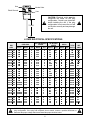
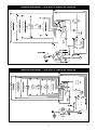
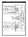
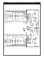
R INSTALLATION AND OPERATING INSTRUCTIONS Models: DMXS-H DMXS-S DMXD-H DMXD-S RACER MERCHANDISERS INTENDED FOR OTHER THAN HOUSEHOLD USE RETAIN THIS MANUAL FOR FUTURE REFERENCE UNIT MUST BE KEPT CLEAR OF COMBUSTIBLES AT ALL TIMES ! FOR YOUR SAFETY: Do not store or use gasoline or other flammable vapors and liquids in the vicinity of this or any other appliance. ! ! WARNING: Improper installation, adjustment, alteration, service or maintenance can cause property damage, injury or death. Read the Installation, Operating and Maintenance Instructions thoroughly before installing or servicing this equipment. ! Initial heating of appliance may generate smoke or fumes and must be done in a well ventilated area. Overexposure to smoke or fumes may cause nausea or dizziness. This equipment has been engineered to provide you with year-round dependable service when used according to the instructions in this manual and standard commercial kitchen practices. ANSI/NSF4 Phone: Fax: Toll Free: Website: E-mail: P/N 8817100 1/06 (307) 634-5801 (307) 637-8071 (800) 752-0863 www.apwwyott.com [email protected] APW WYOTT 1938 Wyott Drive Cheyenne, WY 82007 1 APW Wyott takes pride in the design and quality of our products. When used as intended and with proper care and maintenance, you will experience years of reliable operation from this equipment. To ensure best results, it is important that you read and follow the instructions in this manual carefully. Installation and start-up should be performed by a qualified installer who thoroughly read, understands and follows these instruction. If you have questions concerning the installation, operation, maintenance or service of this product, contact APW Wyott Foodservice Equipment Company’s “ Technical Service Department”. SAFETY PRECAUTIONS Before installing and operating this equipment be sure everyone involved in its operation are fully trained and are aware of all precautions. Accidents and problems can result by a failure to follow fundamental rules and precautions. The following words and symbols, found in this manual, alert you to hazards to the operator, service personnel or the equipment. The words are defined as follows: ! DANGER: This symbol warns of imminent hazard which will result in serious injury or death. ! ! WARNING: This symbol refers to a potential hazard or unsafe practice, which could result in serious injury or death. ! ! CAUTION: This symbol refers to a potential hazard or unsafe practice, which may result in minor or moderate injury or product or property damage. ! ! NOTICE: This symbol refers to information that needs special attention or must be fully understood even though not dangerous. ! IMPORTANT FOR FUTURE REFERENCE: Please complete this information and retain this manual for the life of the equipment. For Warranty Service and/or Parts, this information is required. Model Number: Serial Number: Date Purchased: TABLE OF CONTENTS SECTION 1 2 3 4 5 6 7 8 ITEM PAGE Important Safety Instructions Installation All Models Location Operation Unit Dimensions Plug/Cordset Configuration Electrical Specifications & Diagrams Wiring Diagram 120V Units, DMXS-30 thru 42 Wiring Diagram 120V Units, DMXS-48 thru 60 Wiring Diagram 120V Units, DMXD-30 thru 42 Wiring Diagram 120V Units, DMXD-48 thru 60 Wiring Diagram 240V Units, 50Hz Maintenance General Cleaning Display Light Replacement Accessories Stainless Steel Dividers Parts Lists w/Exploded Views DMXS-H DMXS-S DMXD-H DMXD-S Warranty 2 3 4 4 4 4 5 5 6 7 7 8 9 10 11 11 11 11 11 11 12 12 14 16 18 20 1. IMPORTANT SAFETY INSTRUCTIONS ! IMPORTANT: Read the following important safety instructions to avoid personal injury or death, and to avoid damage to the equipment or property. ! ! WARNING: Plug unit into a properly grounded electrical outlet of the correct voltage, size and plug configuration. If the plug and receptacle do not match, contact a qualified electrician to determine the proper voltage and size and install the proper electrical outlet. ! ! WARNING: Unit is not waterproof. DO NOT submerge in water. Do not operate if it has been submerged in water. ! ! WARNING: To avoid any injury, turn the power switch off at the fuse disconnect switch/circuit breaker or unplug the unit from the power source and allow to cool completely before performing any maintenance or cleaning. ! ! WARNING: To avoid electrical shock, always unplug the unit before performing cleaning or maintenance. ! ! WARNING: Do not place food product directly onto hardcoat surface. Food product must be wrapped, boxed or on a food pan. ! ! WARNING: To avoid electrical shock or personal injury, do not steam clean or use excessive water on the unit. ! ! WARNING: Only light bulbs which meet or exceed N.S.F. Standards, specifically designed for food holding areas must be used. Breakage of light bulbs not specially coated could result in personal injury and/or food contamination. ! ! WARNING: If service is required on this unit, contact your authorized APW Wyott Service Agent, or contact the APW Wyott Service Department directly at (214) 421-7366 or (800) 527-2100; fax (214) 565-0976. ! ! WARNING: This product has no “user” serviceable parts. To avoid damage to the unit or injury to personnel, use only Authorized APW Wyott Service Agents and genuine APW Wyott Parts when service is required.. ! ! WARNING: Genuine APW Wyott Replacement Parts are specified to operate safely in the environments in which they are used. Some aftermarket or generic replacement parts do not have the characteristics that will allow them to operate safely in APW Wyott equipment. It is essential to use APW Wyott Replacement Parts when repairing APW Wyott equipment. Failure to use APW Wyott Replacement Parts may subject operators of the equipment to hazardous electrical voltage, resulting in electrical shock or burn. ! ! CAUTION: Some exterior surfaces on the unit will get hot. Use caution when touching these areas to avoid injury. ! ! CAUTION: Locate the unit at the proper counter height, in an area that is convenient for use. The location should be level to prevent the unit or it’s contents from accidentally falling, and strong enough to support the weight of the unit and food. ! ! CAUTION: The National Sanitation Foundation (NSF) requires that units over 36” (91 cm) in length or weighing more than 80 lbs. (36 kg) to be either sealed or raised on the installation surface. If this unit cannot be sealed at the point of use, 4” (10 cm) legs are included to allow for proper cleaning access below unit. ! ! CAUTION: Use only non-abrasive cleaners. Abrasive cleaners could scratch the finish of your unit, marring it’s appearance and making it susceptible to dirt accumulation. ! ! CAUTION: Only soft cleaning cloths should be used to clean breath protector(s). Breath protector(s) are made of shatterproof polycarbonate and will scratch if proper care is not taken. ! 3 2. INSTALLATION ALL MODELS All APW/Wyott Racer Merchandisers are shipped with most components pre-assembled. Care should be taken when unpacking shipping carton to avoid damage to unit and components enclosed. 1. 2. 3. 4. Remove unit from box. Remove information packet. Remove tape and protective packaging from all surfaces of unit. The unit is supplied with product divider bars. To install them, simply place the bars in the channels provided. The bars can be readily adjusted to separate your holding areas as needed. LOCATION NOTE: The unit must be transported in the upright position. For proper operation and maximum performance, locate the Racer Merchandiser in an area where the ambient air temperature is constant and is a minimum of 70°F (21°C). Areas which are susceptible to active air movements or currents should be avoided, i.e. near exhaust fans or hoods and air conditioning ducts. The data plate for the unit is located on the bottom of the unit near the power cord. Check the voltage requirements on the data plate. Connect the unit only the the voltage configuration specified on the data plate. ! ! CAUTION: Locate the unit at the proper counter height, in an area that is convenient for use. The location should be level to prevent the unit or it’s contents from accidentally falling, and strong enough to support the weight of the unit and food. CAUTION: The National Sanitation Foundation (NSF) requires that units over 36” (91 cm) in length or weighing more than 80 lbs. (36 kg) to be either sealed or raised on the installation surface. If this unit cannot be sealed at the point of use, 4” (10 cm) legs are included to allow for proper cleaning access below unit. ! ! 3. OPERATION The Racer Merchandiser’s power is controlled by the ON/OFF toggle switch. For units with two shelves there are two toggle switches, one for each shelf. You can power the shelves independently.The switch must be on the ON position for the unit to function. The thermostatically controlled base and rear overhead element can be set to any desired heating level as indicated on the control plate. NOTE: Main power switch must be in the ON position for the heated base to function. CE Provision for Earthing Provision for Earthing is located at the rear of the unit. It is designated by this symbol and provides means of earthing terminals to be properly secured to the frame of the unit. Earthing terminals shall not be connected to the neutral terminal. External bonding conductors connected to earthing terminals shall be 2.5 mm2 to 6 mm2 in diameter. ! CAUTION: Some exterior surfaces on the unit will get hot. Use caution when touching these areas to avoid injury. ! ! WARNING: Do not place food product directly onto hardcoat surface. Food product must be wrapped, boxed or on a food pan. ! 4 DMX UNIT DIMENSIONS DMX RACER MERCHANDISERS MODEL # WIDTH HEIGHT DEPTH MODEL # WIDTH HEIGHT DEPTH DMXS-30H DMXS-36H DMXS-42H DMXS-48H DMXS-54H DMXS-60H DMXD-30H DMXD-36H DMXD-42H DMXD-48H DMXD-54H DMXD-60H 30" 36" 42" 48" 54" 60" 30" 36" 42" 48" 54" 60" 18" 18" 18" 18" 18" 18" 29" 29" 29" 29" 29" 29" 27.25" 27.25" 27.25" 27.25" 27.25" 27.25" 27.25" 27.25" 27.25" 27.25" 27.25" 27.25" DMXS-30S DMXS-36S DMXS-42S DMXS-48S DMXS-54S DMXS-60S DMXD-30S DMXD-36S DMXD-42S DMXD-48S DMXD-54S DMXD-60S 30" 36" 42" 48" 54" 60" 30" 36" 42" 48" 54" 60" 22.125" 22.125" 22.125" 22.125" 22.125" 22.125" 33.312" 33.312" 33.312" 33.312" 33.312" 33.312" 27.25" 27.25" 27.25" 27.25" 27.25" 27.25" 27.25" 27.25" 27.25" 27.25" 27.25" 27.25" The Model Numbers And What They Mean: DMX is just the model name. The "S" or the "D" after the DMX stands for Single shelf or Double shelf. The number after the first part of the model number is the complete width of the countertop area. The (H) after the number stands for Horizontal units. The (S) after the number stands for Slanted units. PLUG/CORDSET CONFIGURATION Model DMXS-30S DMXS-30H DMXD-30S DMXD-30H DMXS-36S DMXS-36H DMXD-36S DMXD-36H DMXS-42S DMXS-42H DMXD-42S DMXD-42H DMXS-48S DMXS-48H DMXD-48S DMXD-48H DMXS-54S DMXS-54H DMXD-54S DMXD-54H DMXS-60S DMXS-60H DMXD-60S DMXD-60H Voltage 120 120 120 120 120 120 120 120 120 120 120 120 120 120 120/208 120/208 120 120 120/208 120/208 120 120 120/208 120/208 USA USL 5-15 5-15 5-15 5-15 5-15 5-15 5-15 5-15 5-15 5-15 5-20 5-20 5-15 5-15 14-20 14-20 5-15 5-15 14-20 14-20 5-15 5-15 14-20 14-20 Canada CNL Voltage 5-15 220 5-15 220 5-15 220 5-15 220 5-15 220 5-15 220 5-20 220 5-20 220 5-15 220 5-15 220 5-30 220 5-30 220 5-15 220 5-15 220 14-20 220 14-20 220 5-15 220 5-15 220 14-20 220 14-20 220 5-20 220 5-20 220 14-20 220 14-20 220 Export Model Voltage CEE7/7 SCHUKO 240 CEE7/7 SCHUKO 240 CEE7/7 SCHUKO 240 CEE7/7 SCHUKO 240 CEE7/7 SCHUKO 240 CEE7/7 SCHUKO 240 CEE7/7 SCHUKO 240 CEE7/7 SCHUKO 240 CEE7/7 SCHUKO 240 CEE7/7 SCHUKO 240 CEE7/7 SCHUKO 240 CEE7/7 SCHUKO 240 CEE7/7 SCHUKO 240 CEE7/7 SCHUKO 240 CEE7/7 SCHUKO 240 CEE7/7 SCHUKO 240 CEE7/7 SCHUKO 240 CEE7/7 SCHUKO 240 CEE7/7 SCHUKO 240 CEE7/7 SCHUKO 240 CEE7/7 SCHUKO 240 CEE7/7 SCHUKO 240 CEE7/7 SCHUKO 240 CEE7/7 SCHUKO 240 5 BS-1363 BS-1363 BS-1363 BS-1363 BS-1363 BS-1363 BS-1363 BS-1363 BS-1363 BS-1363 BS-1363 BS-1363 BS-1363 BS-1363 BS-1363 BS-1363 BS-1363 BS-1363 BS-1363 BS-1363 BS-1363 BS-1363 BS-1363 BS-1363 NEMA 5-20P NEMA 14-20P NEMA 5-15P CEE 7/7 Schuko BS 1363 Line 20 AMPS Neutral Line Earth Ground Line 125/250V ! 72.000 CAUTION: Electrical outlet must be configured the same as the plug configuration. Consult your electrician before installing the unit. If the plug configuration is not correct the unit will not function correctly and may damage the unit. ! 4. DMX ELECTRICAL SPECIFICATIONS BOTTOM BLANKET HEATER OVER HEAD DMX UNITS TOP BLANKET HEATER BULBS VOLTS WATTS QTY WATTS QTY WATTS QTY WATTS QTY TOTAL WATTS UNIT AMPS DMXS-30S 120 185 2 225 1 NA NA 60 2 715 5.96 DMXS-30H 120 185 2 225 1 NA NA 60 2 715 5.96 DMXD-30S 120 185 4 225 1 175 1 60 4 1380 11.5 DMXD-30H 120 185 4 225 1 175 1 60 4 1380 11.5 DMXS-36S 120 235 2 275 1 NA NA 60 2 865 7.21 DMXS-36H 120 235 2 275 1 NA NA 60 2 865 7.21 DMXD-36S 120 235 4 275 1 225 1 60 4 1680 14 DMXD-36H 120 235 4 275 1 225 1 60 4 1680 14 8.46 DMXS-42S 120 285 2 325 1 NA NA 60 2 1015 DMXS-42H 120 285 2 325 1 NA NA 60 2 1015 8.46 DMXD-42S 120 285 4 325 1 260 1 60 4 1965 16.38 DMXD-42H 120 285 4 325 1 260 1 60 4 1965 16.38 10.5 DMXS-48S 120 335 2 350 1 NA NA 60 4 1260 DMXS-48H 120 335 2 350 1 NA NA 60 4 1260 10.5 DMXD-48S 120/208 335 4 350 1 300 1 60 8 2470 10.29 DMXD-48H 120/208 335 4 350 1 300 1 60 8 2470 10.29 DMXS-54S 120 380 2 400 1 NA NA 60 4 1400 11.67 DMXS-54H 120 380 2 400 1 NA NA 60 4 1400 11.67 DMXD-54S 120/208 380 4 400 1 325 1 60 8 2725 11.35 DMXD-54H 120/208 380 4 400 1 325 1 60 8 2725 11.35 13 DMXS-60S 120 435 2 450 1 NA NA 60 4 1560 DMXS-60H 120 435 2 450 1 NA NA 60 4 1560 13 DMXD-60S 120/208 435 4 450 1 375 1 60 8 3045 12.69 DMXD-60H 120/208 435 4 450 1 375 1 60 8 3045 12.69 ! WARNING: Plug cabinet into a properly grounded electrical outlet of the correct voltage, size and plug configuration. If the plug and receptacle do not match, contact a qualified electrician to determine the proper voltage and size and install the proper electrical outlet. 6 ! WIRING DIAGRAM 120V UNITS, DMXS-30 THRU 42 15 13 4 11 10 5 7 3 26 14 25 24 22 14 21 1 8 6 9 16 15 23 13 12 2 23 17 BUTT SPLICE BUTT SPLICE BUTT SPLICE 27 18 BUTT SPLICE WIRING DIAGRAM 120V UNITS, DMXS-48 THRU 60 15 4 11 10 30 5 32 7 13 3 14 26 25 22 24 14 21 9 29 6 31 8 1 15 23 12 16 2 23 17 SPLICE 120 VOLT 7 18 SPLICE 13 WIRING DIAGRAM 120V UNITS, DMXD-30 THRU 42 15 4 13 11 10 5 7 3 14 26 25 24 22 14 21 9 6 1 8 15 23 12 16 13 2 23 17 20 19 BUTT SPLICE BUTT SPLICE BUTT SPLICE 27 BUTT SPLICE 18 15 13 BUTT SPLICE 19 20 23 2 12 9 23 6 8 1 21 14 22 14 4 11 10 5 7 16 3 13 15 8 25 24 26 WIRING DIAGRAM 120/208V UNITS, DMXD-48 THRU 60 15 4 11 10 30 5 32 7 13 3 14 25 26 22 24 14 21 9 29 6 31 8 1 15 23 12 16 13 2 23 19 17 SPLICE 18 SPLICE 20 15 13 SPLICE 28 23 2 12 9 23 29 6 31 8 14 22 14 4 11 10 30 5 32 7 3 13 15 9 16 1 21 25 26 24 SPLICE 19 WIRING DIAGRAM 240V, 50HZ UNITS 24 24 25 25 31 31 22 22 HEATERS & LIGHTS FOR TOP SHELF 26 26 21 21 20 20 27 27 34 34 23 23 28 28 28 28 EXISTING WIRE 32 32 BLANKET HEATER FOR MIDDLE SHELF 23 23 30 30 29 29 29 29 30 30 77 88 13 13 31 31 99 44 3 3 10 10 32 32 55 HEATERS & LIGHTS FOR MIDDLE SHELF 66 14 14 34 34 11 11 11 11 EXISTING WIRE BLANKET HEATER FOR BOTTOM SHELF 14 14 1515 12 12 15 15 16 16 13 13 30 30 66 EXISTING WIRE 32 32 THERMOSTAT PILOT LIGHT EXISTING WIRE SWITCH 12 12 13 13 16 16 EXISTING WIRE EXISTING WIRE THERMOSTAT 12 12 13 13 35 35 33 33 17 17 L2 REMOVE JUMPER FROM END TERMINALS 10 11 L1 11 22 18 18 33 33 31 31 34 34 PILOT LIGHT 34 34 19 19 SHIFT JUMPER OVER ONE SPOT SWITCH 13 13 17 17 5. MAINTENANCE GENERAL The APW/Wyott Racer Merchandisers are designed for maximum durability and performance, with minimum maintenance. ! WARNING: To avoid any injury, turn the power switch off at the fuse disconnect switch/circuit breaker or unplug the unit from the power source and allow to cool completely before performing any maintenance or cleaning. ! ! WARNING: To avoid electrical shock or personal injury, do not steam clean or use excessive water on the unit. ! ! WARNING: Unit is not waterproof. DO NOT submerge in water. Do not operate if it has been submerged in water. Do not clean the unit with a water jet. ! ! WARNING: To avoid electrical shock, always unplug the unit before performing cleaning or maintenance. ! CLEANING To preserve the bright finish of the Racer Merchandiser, it is recommended that the exterior and interior surfaces be wiped daily with a damp cloth. Stubborn stains may be removed with a good nonabrasive cleanser. Hard to reach areas should be cleaned with a small brush and mild soap. ! CAUTION: Use only non-abrasive cleaners. Abrasive cleaners could scratch the finish of your unit, marring it’s appearance and making it susceptible to dirt accumulation. Do Not use steel wool, other abrasive cleaners or cleaners/sanitizers containing chlorine, iodine, ammonia or bromine chemicals as these will deteriorate the stainless steel and glass material and shorten the life of the unit. ! ! CAUTION: Do not use a water jet (pressure sprayer) to clean the unit, or component failure could result. ! Clean the glass sides using a common glass cleaner. DISPLAY LIGHT BULB REPLACEMENT The display light is an incandescent light bulb which illuminates the warming area. The bulb has a special coating to guard against injury and food contamination in the event of breakage. 1. To replace the light bulb, disconnect the power supply and wait until the unit has cooled. 2. Bulbs have a threaded base. Unscrew the light bulb from the unit and replace it with a new specially coated incandescent bulb. NOTE: APW Wyott shatter-resistant light bulbs meet N.S.F. Standards for food holding and display areas. ! WARNING: Only bulbs which meet or exceed N.S.F. Standards, specifically designed for food holding areas must be used. Breakage of bulbs not specially coated could result in personal injury and/or food contamination. ! ! WARNING: If service is required on this unit, contact your authorized APW Wyott Service Agent, or contact the APW Wyott Service Department directly at (214) 421-7366 or (800) 527-2100; fax (214) 565-0976. ! ! WARNING: This product has no “user” serviceable parts. To avoid damage to the unit or injury to personnel, use only Authorized APW Wyott Service Agents and genuine APW Wyott Parts when service is required.. ! ! WARNING: Genuine APW Wyott Replacement Parts are specified to operate safely in the environments in which they are used. Some aftermarket or generic replacement parts do not have the characteristics that will allow them to operate safely in APW Wyott equipment. It is essential to use APW Wyott Replacement Parts when repairing APW Wyott equipment. Failure to use APW Wyott Replacement Parts may subject operators of the equipment to hazardous electrical voltage, resulting in electrical shock or burn. ! 6. ACCESSORIES STAINLESS STEEL DIVIDER RODS Additional stainless steel divider rods help to keep product separate in the channels. 11 7. PARTS LISTS & EXPLODED VIEWS PARTS LIST DMXS-H ITEM P/N 1 2 3 4 5 1481510 1301900 8700700 45653000 21779885 21779601 21779886 21779887 21779888 21779889 21779880 21779602 21779881 21779882 21779883 21779884 21779860 21779761 21779861 21779862 21779863 21779864 21779865 21779766 21779866 21779867 21779868 21779869 21779715 21779620 21779716 21779717 21779718 21779624 21779720 21779671 21779724 21779726 21779728 21779730 6 12 7 N/S N/S N/S N/S N/S N/S N/S N/S N/S N/S N/S N/S N/S N/S N/S N/S N/S N/S DESCRIPTION THERMOSTAT TOGGLE SWITCH DPST KNOB INDICATOR LIGHT AMBER INSERT, EXTRUSION 30" RED INSERT, EXTRUSION 36" RED INSERT, EXTRUSION 42" RED INSERT, EXTRUSION 48" RED INSERT, EXTRUSION 54" RED INSERT, EXTRUSION 60" RED PANEL, CONTROL 30" DMX RED PANEL, CONTROL 36" DMX RED PANEL, CONTROL 42" DMX RED PANEL, CONTROL 48" DMX RED PANEL, CONTROL 54" DMX RED PANEL, CONTROL 60" DMX RED EXTRUSION, FRONT SIDE DMX 30" BLACK EXTRUSION, FRONT SIDE DMX 36" BLACK EXTRUSION, FRONT SIDE DMX 42" BLACK EXTRUSION, FRONT SIDE DMX 48" BLACK EXTRUSION, FRONT SIDE DMX 54" BLACK EXTRUSION, FRONT SIDE DMX 60" BLACK EXTRUSION, CONTROL SIDE 30" DMX BLACK EXTRUSION, CONTROL SIDE 36" DMX BLACK EXTRUSION, CONTROL SIDE 42" DMX BLACK EXTRUSION, CONTROL SIDE 48" DMX BLACK EXTRUSION, CONTROL SIDE 54" DMX BLACK EXTRUSION, CONTROL SIDE 60" DMX BLACK ELEMENT, 185W 120V 25.438" DMX-30 ELEMENT, 235W @ 120V DMX 36" ELEMENT, 285W 120V 37.438" DMX-42 ELEMENT, 335W 120V 43.438" DMX-48 ELEMENT, 380W 120V 49.438" DMX-54 ELEMENT, 435W @ 120V DMX 60" ELEMENT, BLANKET 120V 225W 23.750X21.750 ELEMENT BLNKT 120V 195W/OUTER 80W/INNER ELEMENT,BLANKET 120V 325W 35.750X21.750 ELEMENT,BLANKET 120V 350W 41.750X21.750 ELEMENT,BLANKET 120V 400W 47.750X21.750 ELEMENT,BLANKET 120V 450W 53.750X21.750 QTY 1 1 1 1 3 3 3 3 3 3 1 1 1 1 1 1 3 3 3 3 3 3 1 1 1 1 1 1 2 2 2 2 2 2 1 1 1 1 1 1 UNIT SIZE 30 36 42 48 54 60 30 36 42 48 54 60 30 36 42 48 54 60 30 36 42 48 54 60 30 36 42 48 54 60 30 36 42 48 54 60 ITEM 8 9 10 11 12 13 14 15 16 17 18 19 20 21 22 23 24 25 P/N 21779625 8816300 21779606 21779786 21779680 21779618 54001400 1107301 21776245 21776246 21776276 21776216 21776300 21776323 21776348 21776370 21779617 21779617 21779617 21779617 21779617 21779617 54001500 1311800 8430800 8632000 21779811 21779813 21779815 21779817 21779819 21779821 21779828 21779829 21779830 21779831 21779832 21779833 DESCRIPTION GLASS, TEMPERED DMX FLAT DECAL, MECHANDIZER CONTROL PANEL BOTTOM COVER, FLAT SIDE SINGLE RED WELDMENT, RT UPRIGHT FLAT SINGLE WELDMENT,LT UPRIGHT FLAT SINGLE MOUNT, DIODE & RELAY RECTIFIER 600Vrrm 40AMPS TERMINAL BLOCK TUBULAR SCREW RAISED BASE CAP, END RIGHT SIDE CAP, END LEFT SIDE BRACKET, DIVIDER 30" BRACKET, DIVIDER 36" BRACKET, DIVIDER 42" BRACKET, DIVIDER 48" BRACKET, DIVIDER 54" BRACKET, DIVIDER 60" ROD, DIVIDER ROD, DIVIDER ROD, DIVIDER ROD, DIVIDER ROD, DIVIDER ROD, DIVIDER WASHER, SHOULDER FIBRE RELAY,SPDT 120V COIL 15 AMPS NUT, HEX 1/4-28 LEG, 4 INCH ADJ. 2000 LB LOAD CAPACITY DMXS-30H 120V BASE ASSY FRC-BLACK,INSERTS-RED DMXS-36H 120V BASE ASSY FRC-BLACK,INSERTS-RED DMXS-42H 120V BASE ASSY FRC-BLACK,INSERTS-RED DMXS-48H 120V BASE ASSY FRC-BLACK,INSERTS-RED DMXS-54H 120V BASE ASSY FRC-BLACK,INSERTS-RED DMXS-60H 120V BASE ASSY FRC-BLACK,INSERTS-RED DMX-30 120V TOP ASSY. FRC-BLACK,INSERTS-RED DMX-36 120V TOP ASSY FRC-BLACK,INSERTS-RED DMX-42 120V TOP ASSY FRC-BLACK,INSERTS-RED DMX-48 120V TOP ASSY FRC-BLACK,INSERTS-RED DMX-54 120V TOP ASSY FRC-BLACK,INSERTS-RED DMX-60 120V TOP ASSY FRC-BLACK,INSERTS-RED N/S = NOT SHOWN QTY 2 1 2 1 1 1 1 1 4 4 4 4 4 4 4 4 10 12 14 16 18 20 2 1 1 4 1 1 1 1 1 1 1 1 1 1 1 1 UNIT SIZE 30 36 42 48 54 60 30 36 42 48 54 60 30 36 42 48 54 60 30 36 42 48 54 60 EXPLODED VIEW DMXS-H 12 “B” 25 6 15 14 20 13 8 21 19 13 22 DETAIL “A” 17 18 4 10 7 9 8 24 1 11 3 2 DETAIL “B” “A” 23 5 16 PARTS LIST DMXS-S ITEM P/N 1 2 3 4 5 1481510 1301900 8700700 45653000 21779885 21779601 21779886 21779887 21779888 21779889 21779880 21779602 21779881 21779882 21779883 21779884 21779860 21779761 21779861 21779862 21779863 21779864 21779865 21779766 21779866 21779867 21779868 21779869 21779715 21779620 21779716 21779717 21779718 21779624 21779720 21779671 21779724 21779726 21779728 21779730 6 7 14 N/S N/S N/S N/S N/S N/S N/S N/S N/S N/S N/S N/S N/S N/S N/S N/S N/S N/S DESCRIPTION THERMOSTAT TOGGLE SWITCH DPST KNOB INDICATOR LIGHT AMBER INSERT, EXTRUSION 30" RED INSERT, EXTRUSION 36" RED INSERT, EXTRUSION 42" RED INSERT, EXTRUSION 48" RED INSERT, EXTRUSION 54" RED INSERT, EXTRUSION 60" RED PANEL, CONTROL 30" DMX RED PANEL, CONTROL 36" DMX RED PANEL, CONTROL 42" DMX RED PANEL, CONTROL 48" DMX RED PANEL, CONTROL 54" DMX RED PANEL, CONTROL 60" DMX RED EXTRUSION, FRONT SIDE DMX 30" BLACK EXTRUSION, FRONT SIDE DMX 36" BLACK EXTRUSION, FRONT SIDE DMX 42" BLACK EXTRUSION, FRONT SIDE DMX 48" BLACK EXTRUSION, FRONT SIDE DMX 54" BLACK EXTRUSION, FRONT SIDE DMX 60" BLACK EXTRUSION, CONTROL SIDE 30" DMX BLACK EXTRUSION, CONTROL SIDE 36" DMX BLACK EXTRUSION, CONTROL SIDE 42" DMX BLACK EXTRUSION, CONTROL SIDE 48" DMX BLACK EXTRUSION, CONTROL SIDE 54" DMX BLACK EXTRUSION, CONTROL SIDE 60" DMX BLACK ELEMENT, 185W 120V 25.438" DMX-30 ELEMENT, 235W @ 120V DMX 36" ELEMENT, 285W 120V 37.438" DMX-42 ELEMENT, 335W 120V 43.438" DMX-48 ELEMENT, 380W 120V 49.438" DMX-54 ELEMENT, 435W @ 120V DMX 60" ELEMENT, BLANKET 120V 225W 23.750X21.750 ELEMENT BLNKT 120V 195W/OUTER 80W/INNER ELEMENT,BLANKET 120V 325W 35.750X21.750 ELEMENT,BLANKET 120V 350W 41.750X21.750 ELEMENT,BLANKET 120V 400W 47.750X21.750 ELEMENT,BLANKET 120V 450W 53.750X21.750 QTY 1 1 1 1 3 3 3 3 3 3 1 1 1 1 1 1 3 3 3 3 3 3 1 1 1 1 1 1 2 2 2 2 2 2 1 1 1 1 1 1 UNIT SIZE 30 36 42 48 54 60 30 36 42 48 54 60 30 36 42 48 54 60 30 36 42 48 54 60 30 36 42 48 54 60 30 36 42 48 54 60 ITEM 8 9 10 11 12 13 14 15 16 17 18 19 20 21 22 23 24 25 26 P/N 21779669 8816300 21779608 21779607 21779630 21779635 21779618 54001400 1107301 21776245 21776246 21776276 21776216 21776300 21776323 21776348 21776370 21779617 21779617 21779617 21779617 21779617 21779617 54001500 1311800 8430800 8632000 21779810 21779812 21779834 21779836 21779838 21779840 21779828 21779829 21779830 21779831 21779832 21779833 DESCRIPTION GLASS, TEMPERED DMX DECAL, MECHANDIZER CONTROL PANEL BOTTOM COVER LT SINGLE SLANT LT SIDE RED COVER, SINGLE SLANT RT SIDE RED UPRIGHT, RT SIDE WELDMENT UPRIGHT, LT SIDE WELDMENT MOUNT, DIODE & RELAY RECTIFIER 600Vrrm 40AMPS TERMINAL BLOCK TUBULAR SCREW RAISED BASE CAP, END RIGHT SIDE CAP, END LEFT SIDE BRACKET, DIVIDER 30" BRACKET, DIVIDER 36" BRACKET, DIVIDER 42" BRACKET, DIVIDER 48" BRACKET, DIVIDER 54" BRACKET, DIVIDER 60" ROD, DIVIDER ROD, DIVIDER ROD, DIVIDER ROD, DIVIDER ROD, DIVIDER ROD, DIVIDER WASHER, SHOULDER FIBRE RELAY,SPDT 120V COIL 15 AMPS NUT, HEX 1/4-28 LEG, 4 INCH ADJ. 2000 LB LOAD CAPACITY DMX-30S 120V BASE ASSY FRC-BLACK,INSERTS-RED DMX-36S 120V BASE ASSY FRC-BLACK,INSERTS-RED DMX-42S 120V BASE ASSY FRC-BLACK,INSERTS-RED DMX-48S 120V BASE ASSY FRC-BLACK,INSERTS-RED DMX-54S 120V BASE ASSY FRC-BLACK,INSERTS-RED DMX-60S 120V BASE ASSY FRC-BLACK,INSERTS-RED DMX-30 120V TOP ASSY FRC-BLACK,INSERTS-RED DMX-36 120V TOP ASSY FRC-BLACK,INSERTS-RED DMX-42 120V TOP ASSY FRC-BLACK,INSERTS-RED DMX-48 120V TOP ASSY FRC-BLACK,INSERTS-RED DMX-54 120V TOP ASSY FRC-BLACK,INSERTS-RED DMX-60 120V TOP ASSY FRC-BLACK,INSERTS-RED N/S = NOT SHOWN QTY 2 1 1 1 1 1 1 1 1 4 4 2 2 2 2 2 2 5 6 7 8 9 10 2 1 1 4 1 1 1 1 1 1 1 1 1 1 1 1 UNIT SIZE 30 36 42 48 54 60 30 36 42 48 54 60 30 36 42 48 54 60 30 36 42 48 54 60 EXPLODED VIEW DMXS-S 8 11 12 1 26 9 2 7 8 18 15 6 10 20 13 19 17 DETAIL “A” “A” 16 22 15 21 24 5 4 3 25 “B” 14 23 DETAIL “B” PARTS LIST DMXD-H ITEM P/N 1 2 3 4 5 1481510 1301900 8700700 45653000 21779885 21779601 21779886 21779887 21779888 21779889 21779880 21779602 21779881 21779882 21779883 21779884 21779860 21779761 21779861 21779862 21779863 21779864 21779865 21779766 21779866 21779867 21779868 21779869 21779715 21779620 21779716 21779717 21779718 21779624 21779720 21779671 21779724 21779726 21779728 21779730 21779625 8816300 21779605 6 7 16 N/S N/S N/S N/S N/S N/S N/S N/S N/S N/S N/S N/S N/S N/S N/S N/S N/S N/S 8 9 10 DESCRIPTION THERMOSTAT TOGGLE SWITCH DPST KNOB INDICATOR LIGHT AMBER INSERT, EXTRUSION 30" RED INSERT, EXTRUSION 36" RED INSERT, EXTRUSION 42" RED INSERT, EXTRUSION 48" RED INSERT, EXTRUSION 54" RED INSERT, EXTRUSION 60" RED PANEL, CONTROL 30" DMX RED PANEL, CONTROL 36" DMX RED PANEL, CONTROL 42" DMX RED PANEL, CONTROL 48" DMX RED PANEL, CONTROL 54" DMX RED PANEL, CONTROL 60" DMX RED EXTRUSION, FRONT SIDE DMX 30" BLACK EXTRUSION, FRONT SIDE DMX 36" BLACK EXTRUSION, FRONT SIDE DMX 42" BLACK EXTRUSION, FRONT SIDE DMX 48" BLACK EXTRUSION, FRONT SIDE DMX 54" BLACK EXTRUSION, FRONT SIDE DMX 60" BLACK EXTRUSION, CONTROL SIDE 30" DMX BLACK EXTRUSION, CONTROL SIDE 36" DMX BLACK EXTRUSION, CONTROL SIDE 42" DMX BLACK EXTRUSION, CONTROL SIDE 48" DMX BLACK EXTRUSION, CONTROL SIDE 54" DMX BLACK EXTRUSION, CONTROL SIDE 60" DMX BLACK ELEMENT, 185W 120V 25.438" DMX-30 ELEMENT, 235W @ 120V DMX 36" ELEMENT, 285W 120V 37.438" DMX-42 ELEMENT, 335W 120V 43.438" DMX-48 ELEMENT, 380W 120V 49.438" DMX-54 ELEMENT, 435W @ 120V DMX 60" ELEMENT, BLANKET 120V 225W 23.750X21.750 ELEMENT BLNKT 120V 195W/OUTER 80W/INNER ELEMENT,BLANKET 120V 325W 35.750X21.750 ELEMENT,BLANKET 120V 350W 41.750X21.750 ELEMENT,BLANKET 120V 400W 47.750X21.750 ELEMENT,BLANKET 120V 450W 53.750X21.750 GLASS, TEMPERED DMX FLAT DECAL, MECHANDIZER CONTROL PANEL BOTTOM COVER, FLAT SIDE SINGLE RED QTY 2 2 2 2 4 4 4 4 4 4 2 2 2 2 2 2 4 4 4 4 4 4 2 2 2 2 2 2 4 4 4 4 4 4 1 1 1 1 1 1 4 1 2 UNIT SIZE 30 36 42 48 54 60 30 36 42 48 54 60 30 36 42 48 54 60 30 36 42 48 54 60 30 36 42 48 54 60 30 36 42 48 54 60 ITEM 11 12 13 14 15 16 17 18 19 20 21 22 23 24 25 26 27 P/N 21779785 21779685 21779618 54001400 1107301 21776245 21776246 21776276 21776216 21776300 21776323 21776348 21776370 21779617 21779617 21779617 21779617 21779617 21779617 54001500 1311800 8430800 8632000 8816600 21779811 21779813 21779815 21779817 21779819 21779821 21779828 21779829 21779830 21779831 21779832 21779833 21779822 21779823 21779824 21779825 21779826 21779827 DESCRIPTION WELDMENT, RT UPRIGHT DOUBLE FLAT WELDMENT,LT UPRIGHT DOUBLE FLAT MOUNT, DIODE & RELAY RECTIFIER 600Vrrm 40AMPS TERMINAL BLOCK TUBULAR SCREW RAISED BASE CAP, END RIGHT SIDE CAP, END LEFT SIDE BRACKET, DIVIDER 30" BRACKET, DIVIDER 36" BRACKET, DIVIDER 42" BRACKET, DIVIDER 48" BRACKET, DIVIDER 54" BRACKET, DIVIDER 60" ROD, DIVIDER ROD, DIVIDER ROD, DIVIDER ROD, DIVIDER ROD, DIVIDER ROD, DIVIDER WASHER, SHOULDER FIBRE RELAY,SPDT 120V COIL 15 AMPS NUT, HEX 1/4-28 LEG, 4 INCH ADJ. 2000 LB LOAD CAPACITY DECAL,MERCHANDISER CONTROL PANEL TOP DMXS-30H 120V BASE ASSY FRC-BLACK,INSERTS-RED DMXS-36H 120V BASE ASSY FRC-BLACK,INSERTS-RED DMXS-42H 120V BASE ASSY FRC-BLACK,INSERTS-RED DMXS-48H 120/208V BASE ASSY FRC-BLACK,INSERTS-RED DMXS-54H 120/208V BASE ASSY FRC-BLACK,INSERTS-RED DMXS-60H 120/208V BASE ASSY FRC-BLACK,INSERTS-RED DMX-30 120V TOP ASSY. FRC-BLACK,INSERTS-RED DMX-36 120V TOP ASSY FRC-BLACK,INSERTS-RED DMX-42 120V TOP ASSY FRC-BLACK,INSERTS-RED DMX-48 120V TOP ASSY FRC-BLACK,INSERTS-RED DMX-54 120V TOP ASSY FRC-BLACK,INSERTS-RED DMX-60 120V TOP ASSY FRC-BLACK,INSERTS-RED DMX-30 120V MID ASSY. FRC-BLACK,INSERTS-RED DMX-36 120V MID ASSY FRC-BLACK,INSERTS-RED DMX-42 120V MID ASSY FRC-BLACK,INSERTS-RED DMX-48 120V MID ASSY FRC-BLACK,INSERTS-RED DMX-54 120V MID ASSY FRC-BLACK,INSERTS-RED DMX-60 120V MID ASSY FRC-BLACK,INSERTS-RED N/S = NOT SHOWN QTY 1 1 2 2 2 6 6 4 4 4 4 4 4 10 12 14 16 18 20 4 2 2 4 1 1 1 1 1 1 1 1 1 1 1 1 1 1 1 1 1 1 1 UNIT SIZE 30 36 42 48 54 60 30 36 42 48 54 60 30 36 42 48 54 60 30 36 42 48 54 60 30 36 42 48 54 60 EXPLODED VIEW DMXD-H 8 12 24 10 1 26 18 4 2 19 27 8 9 16 17 7 3 DETAIL “A” 6 5 15 6 17 21 25 11 10 14 23 “B” “A” 20 13 22 DETAIL “B” PARTS LIST DMXD-S ITEM P/N 1 2 3 4 5 1481510 1301900 8700700 45653000 21779885 21779601 21779886 21779887 21779888 21779889 21779880 21779602 21779881 21779882 21779883 21779884 21779860 21779761 21779861 21779862 21779863 21779864 21779865 21779766 21779866 21779867 21779868 21779869 21779715 21779620 21779716 21779717 21779718 21779624 21779720 21779671 21779724 21779726 21779728 21779730 21779625 8816300 21779608 21779607 6 7 18 N/S N/S N/S N/S N/S N/S N/S N/S N/S N/S N/S N/S N/S N/S N/S N/S N/S N/S 8 9 10 11 DESCRIPTION THERMOSTAT TOGGLE SWITCH DPST KNOB INDICATOR LIGHT AMBER INSERT, EXTRUSION 30" RED INSERT, EXTRUSION 36" RED INSERT, EXTRUSION 42" RED INSERT, EXTRUSION 48" RED INSERT, EXTRUSION 54" RED INSERT, EXTRUSION 60" RED PANEL, CONTROL 30" DMX RED PANEL, CONTROL 36" DMX RED PANEL, CONTROL 42" DMX RED PANEL, CONTROL 48" DMX RED PANEL, CONTROL 54" DMX RED PANEL, CONTROL 60" DMX RED EXTRUSION, FRONT SIDE DMX 30" BLACK EXTRUSION, FRONT SIDE DMX 36" BLACK EXTRUSION, FRONT SIDE DMX 42" BLACK EXTRUSION, FRONT SIDE DMX 48" BLACK EXTRUSION, FRONT SIDE DMX 54" BLACK EXTRUSION, FRONT SIDE DMX 60" BLACK EXTRUSION, CONTROL SIDE 30" DMX BLACK EXTRUSION, CONTROL SIDE 36" DMX BLACK EXTRUSION, CONTROL SIDE 42" DMX BLACK EXTRUSION, CONTROL SIDE 48" DMX BLACK EXTRUSION, CONTROL SIDE 54" DMX BLACK EXTRUSION, CONTROL SIDE 60" DMX BLACK ELEMENT, 185W 120V 25.438" DMX-30 ELEMENT, 235W @ 120V DMX 36" ELEMENT, 285W 120V 37.438" DMX-42 ELEMENT, 335W 120V 43.438" DMX-48 ELEMENT, 380W 120V 49.438" DMX-54 ELEMENT, 435W @ 120V DMX 60" ELEMENT, BLANKET 120V 225W 23.750X21.750 ELEMENT BLNKT 120V 195W/OUTER 80W/INNER ELEMENT,BLANKET 120V 325W 35.750X21.750 ELEMENT,BLANKET 120V 350W 41.750X21.750 ELEMENT,BLANKET 120V 400W 47.750X21.750 ELEMENT,BLANKET 120V 450W 53.750X21.750 GLASS, TEMPERED DMX FLAT DECAL, MECHANDIZER CONTROL PANEL BOTTOM COVER LT SINGLE SLANT LT SIDE RED COVER, SINGLE SLANT RT SIDE RED QTY 2 2 2 2 4 4 4 4 4 4 2 2 2 2 2 2 4 4 4 4 4 4 2 2 2 2 2 2 4 4 4 4 4 4 1 1 1 1 1 1 4 1 1 1 UNIT SIZE 30 36 42 48 54 60 30 36 42 48 54 60 30 36 42 48 54 60 30 36 42 48 54 60 30 36 42 48 54 60 30 36 42 48 54 60 ITEM 12 13 14 15 16 17 18 19 20 21 22 23 24 25 26 27 28 P/N 21779630 21779635 21779618 54001400 1107301 21776245 21776246 21776276 21776216 21776300 21776323 21776348 21776370 21779617 21779617 21779617 21779617 21779617 21779617 54001500 1311800 8430800 8632000 8816600 21779810 21779812 21779814 21779816 21779818 21779820 21779828 21779829 21779830 21779831 21779832 21779833 21779822 21779823 21779824 21779825 21779826 21779827 DESCRIPTION UPRIGHT, RT SIDE WELDMENT UPRIGHT, LT SIDE WELDMENT MOUNT, DIODE & RELAY RECTIFIER 600Vrrm 40AMPS TERMINAL BLOCK TUBULAR SCREW RAISED BASE CAP, END RIGHT SIDE CAP, END LEFT SIDE BRACKET, DIVIDER 30" BRACKET, DIVIDER 36" BRACKET, DIVIDER 42" BRACKET, DIVIDER 48" BRACKET, DIVIDER 54" BRACKET, DIVIDER 60" ROD, DIVIDER ROD, DIVIDER ROD, DIVIDER ROD, DIVIDER ROD, DIVIDER ROD, DIVIDER WASHER, SHOULDER FIBRE RELAY,SPDT 120V COIL 15 AMPS NUT, HEX 1/4-28 LEG, 4 INCH ADJ. 2000 LB LOAD CAPACITY DECAL,MERCHANDISER CONTROL PANEL TOP DMX-30S 120V BASE ASSY FRC-BLACK,INSERTS-RED DMX-36S 120V BASE ASSY FRC-BLACK,INSERTS-RED DMX-42S 120V BASE ASSY FRC-BLACK,INSERTS-RED DMX-48S 120/208V BASE ASSY FRC-BLACK,INSERTS-RED DMX-54S 120/208V BASE ASSY FRC-BLACK,INSERTS-RED DMX-60S 120/208V BASE ASSY FRC-BLACK,INSERTS-RED DMX-30 120V TOP ASSY FRC-BLACK,INSERTS-RED DMX-36 120V TOP ASSY FRC-BLACK,INSERTS-RED DMX-42 120V TOP ASSY FRC-BLACK,INSERTS-RED DMX-48 120V TOP ASSY FRC-BLACK,INSERTS-RED DMX-54 120V TOP ASSY FRC-BLACK,INSERTS-RED DMX-60 120V TOP ASSY FRC-BLACK,INSERTS-RED DMX-30 120V MID ASSY. FRC-BLACK,INSERTS-RED DMX-36 120V MID ASSY FRC-BLACK,INSERTS-RED DMX-42 120V MID ASSY FRC-BLACK,INSERTS-RED DMX-48 120V MID ASSY FRC-BLACK,INSERTS-RED DMX-54 120V MID ASSY FRC-BLACK,INSERTS-RED DMX-60 120V MID ASSY FRC-BLACK,INSERTS-RED N/S = NOT SHOWN QTY 1 1 2 2 2 6 6 4 4 4 4 4 4 10 12 14 16 18 20 4 2 2 4 1 1 1 1 1 1 1 1 1 1 1 1 1 1 1 1 1 1 1 UNIT SIZE 30 36 42 48 54 60 30 36 42 48 54 60 30 36 42 48 54 60 30 36 42 48 54 60 30 36 42 48 54 60 EXPLODED VIEW DMXD-S 11 8 25 12 27 1 8 4 2 7 19 9 3 19 DETAIL “A” 28 10 18 5 16 6 22 15 14 20 17 13 “B” 24 26 21 “A” DETAIL “B” 23 8. APW WYOTT EQUIPMENT LIMITED WARRANTY APW Wyott Foodservice Equipment Company warrants it's equipment against defects in materials and workmanship, subject to the following conditions: This warranty applies to the original owner only and is not assignable. Should any product fail to function in its intended manner under normal use within the limits defined in this warranty, at the option of APW Wyott such product will be repaired or replaced by APW Wyott or its Authorized Service Agency. APW Wyott will only be responsible for charges incurred or service performed by its Authorized Service Agencies. The use of other than APW Wyott Authorized Service Agencies will void this warranty and APW Wyott will not be responsible for such work or any charges associated with same. The closest APW Wyott Authorized Service Agent must be used. This warranty covers products shipped into the 48 contiguous United States, Hawaii, metropolitan areas of Alaska and Canada. There will be no labor coverage for equipment located on any island not connected by roadway to the mainland. Warranty coverage on products used outside the 48 contiguous United States, Hawaii, and metropolitan areas of Alaska and Canada may vary. Contact the international APW Wyott distributor, dealer, or service agency for details. Time Period One year for parts and one year for labor, effective from the date of purchase by the original owner. The Authorized Service Agency may, at their option, require proof of purchase. Parts replaced under this warranty are warranted for the un-expired portion of the original product warranty only. Exceptions *Gas/Electric Cookline: Models GCB, GCRB, GF, GGM, GGT, CHP-H, EF, EG, EHP. Three (3) Year Warranty on all component parts, except switches and thermostats. (2 additional years on parts only. No labor on second or third year.) *Broiler Briquettes, Rock Grates, Cooking Grates, Burner Shields, Fireboxes: *Heat Strips: *Glass Windows, Doors, Seals, Rubber Seals, Light Bulbs: Models FD, FDL, FDD, FDDL. 90 Day Material Only. No Labor. Two (2) Year Warranty on element only. 90 Day Material Only. No labor second year. No Labor. In all cases, parts covered by extended warranty will be shipped FOB the factory after the first year. Portable Carry In Products Equipment weighing over 70 pounds or permanently installed will be serviced on-site as per the terms of this warranty. Equipment weighing 70 pounds or under, and which is not permanently installed, i.e. with cord and plug, is considered portable and is subject to the following warranty handling limitations. If portable equipment fails to operate in its intended manner on the first day of connection, or use, at APW Wyott's option or its Authorized Service Agency, it will be serviced on site or replaced. From day two through the conclusion of this warranty period, portable units must be taken to or sent prepaid to the APW Wyott Authorized Service Agency for in-warranty repairs. No mileage or travel charges are allowed on portable units after the first day of use. If the customer wants on-site service, they may receive same by paying the travel and mileage charges. Exceptions to this rule: (1) countertop warmers and cookers, which are covered under the Enhanced Warranty Program, and (2) toasters or rollergrills which have in store service. Exclusions The following conditions are not covered by warranty: *Equipment failure relating to improper installation, improper utility connection or supply and problems due to ventilation. *Equipment that has not been properly maintained, calibration of controls, adjustments, damage from improper cleaning and water damage to controls. *Equipment that has not been used in an appropriate manner, or has been subject to misuse or misapplication, neglect, abuse, accident, alteration, negligence, damage during transit, delivery or installation, fire, flood, riot or act of god. *Equipment that has the model number or serial number removed or altered. If the equipment has been changed, altered, modified or repaired by other than an Authorized Service Agency during or after the warranty period, then the manufacturer shall not be liable for any damages to any person or to any property, which may result from the use of the equipment thereafter. This warranty does not cover services performed at overtime or premium labor rates. Should service be required at times which normally involve overtime or premium labor rates, the owner shall be charged for the difference between normal service rates and such premium rates. APW Wyott does not assume any liability for extended delays in replacing or repairing any items beyond its control. In all cases, the use of other than APW Wyott Authorized OEM Replacement Parts will void this warranty. This equipment is intended for commercial use only. Warranty is void if equipment is installed in other than commercial application. Water Quality Requirements Water supply intended for a unit that has in excess of 3.0 grains of hardness per gallon (GPG) must be treated or softened before being used. Water containing over 3.0 GPG will decrease the efficiency and reduce the operation life of the unit. Note: Product failure caused by liming or sediment buildup is not covered under warranty. THE FOREGOING WARRANTY IS IN LIEU OF ANY AND ALL OTHER WARRANTIES EXPRESSED OR IMPLIED INCLUDING ANY IMPLIED WARRANTY OF MERCHANTABILITY OR FITNESS FOR PARTICULAR PURPOSES AND CONSTITUTES THE ENTIRE LIABILITY OF APW WYOTT. IN NO EVENT DOES THE LIMITED WARRANTY EXTEND BEYOND THE TERMS STATED HEREIN. 9/05 20