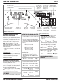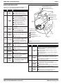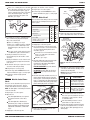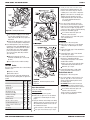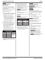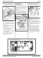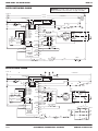
1
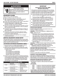
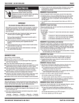
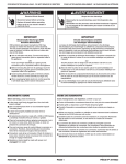
TECH SHEET - DO NOT DISCARD
PAGE 1
WARNING
Electrical Shock Hazard
Disconnect power before
servicing.
Replace all parts and
panels before operating.
Failure to do so can
result in death or
electrical shock.
IMPORTANT
Electrostatic Discharge Sensitive
Electronics (ESD)
ESD problems are present everywhere. ESD
may damage or weaken the machine control
electronics. The new control assembly may
appear to work well after repair is finished,
but failure may occur at a later date due to
ESD stress.
Use an anti-static wrist strap. Connect
wrist strap to green ground connection point
or unpainted metal in the appliance -ORTouch your finger repeatedly to a green
ground connection point or unpainted metal
in the appliance.
Before removing the part from its package,
touch the anti-static bag to a green ground
connection point or unpainted metal in the
appliance.
Avoid touching electronic parts or terminal
contacts; handle machine control
electronics by edges only.
When repackaging failed machine control
electronics in anti-static bag, observe above
instructions.
DIAGNOSTIC GUIDE
Before servicing, check the following:
Make sure there is power at the wall outlet.
Has a household fuse blown or circuit breaker
tripped? Was a regular fuse used? Use a
time-delay fuse.
Is dryer vent properly installed and clear of lint
or obstructions?
All tests/checks should be made with a VOM
(volt-ohm-milliammeter) or DVM (digitalvoltmeter) having a sensitivity of 20,000 Ω
per volt DC or greater.
pressed into connector far enough to engage
metal barbs.
DIAGNOSTIC: Console Buttons and
Indicators
Resistance checks must be made with dryer
unplugged or power disconnected.
Pressing buttons and rotating the cycle selector
will turn off the corresponding indicator and sound
a beep as shown in figure 1, page 2.
DIAGNOSTIC TESTS
These tests allow service personnel to test and
verify all inputs to the machine control electronics.
You may want to do a quick and overall checkup
of the dryer with these tests before going to
specific troubleshooting tests.
ACTIVATING THE DIAGNOSTIC
TEST MODE
1. Be sure the dryer is in standby mode (plugged
in with all indicators off, or with only the Done
indicator on).
2. Select any one button (except Pause/Cancel
and Controls Lock/Unlock) and follow the steps
below, using the same button (remember the
button):
Press/
hold 2
seconds
Release
for 2
seconds
Press/
hold 2
seconds
Release
for 2
seconds
Press/
hold 2
seconds
3. If this test mode has been entered successfully,
all indicators on the console are illuminated for
5 seconds with 8:88 showing in the Estimated
Time Remaining three-digit display. If there are
no saved fault codes or active fault codes, all
indicators on the console will momentarily turn
off, then stay on with 8:88 displayed. Continue
with diagnostics.
4. If entry into Diagnostic Test Mode is
unsuccessful, choose a different button (except
Pause/Cancel and Controls Lock/Unlock) and
repeat step 2.
If no indicators come on after repeating step
2 using a different button, go to TEST #1,
page 4.
DIAGNOSTIC: Active Fault Codes
If there is an active fault code, it will be flashing in
the display. Review the Display Fault/Error Codes
table, page 3, for the recommended procedure.
If there is no active fault code, 8:88 will be
displayed and all of the indicator lights will be
turned on.
DIAGNOSTIC: Saved Fault Codes
If there are saved fault codes, the most recent
fault code will show “F:” and flash “XX” where XX
is the fault code.
Check all connections before replacing
components. Look for broken or loose wires,
failed terminals, or wires not pressed into
connectors far enough.
Press and release
the same button
used to activate
diagnostics
beep
tone
A potential cause of a control not functioning
is corrosion on connections. Observe
connections and check for continuity with
an ohmmeter.
Repeat
beep
tone
Connectors: Look at top of connector. Check
for broken or loose wires. Check for wires not
FOR SERVICE TECHNICIAN’S USE ONLY
Repeat
Repeat
Second most recent
fault code is
displayed.
Pressing
(more time) will toggle the
left digit and colon on the display while
sounding a beep.
Pressing
(less time) will toggle the
right two digits on the display while
sounding a beep.
Pressing the Cycle Signal button will
activate the Line Voltage Test. See
DIAGNOSTIC: Displaying Line Voltage,
page 2.
If indicators fail to come on and beep after
pressing buttons and rotating the cycle
selector, go to TEST #6, page 8.
DIAGNOSTIC: Door Switch
Opening the door should cause a beep and an
alphanumeric number (such as P :3E ) to be
displayed. Closing the door should cause a beep
and 8:88 to be displayed.
If opening the door fails to cause a beep and
a number and letter to be displayed, go to
TEST #7, page 9.
NOTE: Opening the door while in Diagnostic Test
Mode may not activate the drum light. The light
will come on when Start is pressed, or upon
opening the door after the Diagnostic Test Mode
has been canceled.
DIAGNOSTIC: Moisture Sensor
1. Open the door and locate two metal strips on
the inside of the dryer. Using a wet cloth or one
finger, jointly touch both strips.
If a continuous beep tone is heard and an
alphanumeric number is displayed on the
console, the sensor is OK.
If a continuous beep tone is not heard, or
if a continuous beep tone is heard before
touching both moisture strips, go to step 2.
2. Check to see if there is water in the dryer
around the moisture strips.
If no water is present, go to TEST #5,
page 8.
If water is present, wipe the strips off
with a dry cloth and repeat step 1.
If wiping the strips does not stop the
beeping, run a timed dry cycle for 2 minutes
to dry out the drum, then repeat this
diagnostic test.
Third most recent fault
code is displayed.
Fourth most recent
beep
fault code is
tone
displayed.
All indicators momentarily turn
off, then stay on.
PART NO. W10258368B
TECH SHEET - DO NOT DISCARD
Power button controls
its own indicator and
Cycle Status LEDs.
Controls Lock/Unlock button
controls LED below button.
PAGE 2
“Less Time” button
turns the middle and
right digit of the
display on or off.
Start button controls its own indicator,
starts dryer, and displays version information.
Rotating this Cycle
Selector turns cycle
LEDs on or off.
Turns off all
LEDs and exits
diagnostics.
Drum Light button
controls LED
below button.
Each button
controls all LEDs
above button
(Green-Amber-Off).
Figure 1. Console Diagnostics.
DIAGNOSTIC: Motor, Heater, Water,
Drum Light, and Console ID
Close the door. Press the Start button. The motor,
heater, drum light, and water valve (steam models
only) will turn on. Continuing to press the Start
button will display the project codes and software
revisions. These codes are not relevant to the
service of the dryer and can be ignored.
NOTE: The console buttons only control the
indicator lights in Diagnostic Test Mode. When the
buttons are pressed, the corresponding features
will not be activated.
If the motor does not turn on, go to TEST #3,
page 5.
If no heat is detected, go to TEST #4, page 6.
Steam Models Only:
If no water is detected, go to TEST #8, page 9.
NOTE: Press Pause/Cancel when the test is
complete to turn off the dryer. If the dryer
is left running in Diagnostic Test Mode, water
will build up in the drum.
ACTIVATING THE MANUAL LOAD TEST
1. Be sure the dryer is in standby mode (plugged
in with all indicators off, or with only the Done
indicator on).
2. Select any one button (except Pause/Cancel
and Controls Lock/Unlock) and follow the steps
below, using the same button (remember the
button):
a. Press/hold 2 seconds
b. Release for 2 seconds
c. Press/hold 2 seconds
d. Release for 2 seconds
e. Press/hold 2 seconds
f. Release for 2 seconds
g. Press/hold 2 seconds
Steam Models Only:
The motor starts right away, the “Steam”
Status LED comes on, and “0” (zero) is
displayed (this step starts the Manual Load
sequence):
1.
DIAGNOSTIC: Displaying Line Voltage
If the line voltage is not seen on L2, the display
will flash L 2. Go to TEST #1, page 4.
DEACTIVATING THE DIAGNOSTIC
TEST MODE
Press the Pause/Cancel button to exit diagnostics.
“Steam” Status
LED turns on.
0:00 is
displayed.
Wrinkle Shield button
controls its own indicator.
Button Sound button
Cycle Signal button
controls all LEDs
controls all LEDs above
above button
button (Green-Amber-Off)
(Green-Amber-Off).
and starts displaying
Line Voltage Diagnostic.
Non-Steam Models Only:
The motor starts right away, the “Sensing”
Status LED comes on, and “0” (zero) is
displayed (this step starts the Manual Load
sequence):
1.
Motor turns
on.
“Sensing” Status
LED turns on.
0:00 is
displayed.
Now press any key (except Pause/Cancel and
Controls Lock/Unlock) and the control will
advance through each step of the following
sequence:
2. Motor + heater.
“Damp” Status
LED turns on.
0:02 is
displayed.
3.
Motor + heater
+ drum light.
“Cool Down”
Status LED
turns on.
0:03 is
displayed.
4.
All loads turn
off.
“Done” Status
LED turns on.
0:04 is
displayed.
DEACTIVATING THE MANUAL
LOAD TEST
Press the Pause/Cancel button to exit this mode.
Now press any key (except Pause/Cancel and
Controls Lock/Unlock) and the control will
advance through each step of the following
sequence:
Used to display the line voltage currently being
measured by the machine control:
After entering the Diagnostic Test Mode, waiting
for the 5 second delay, and cycling through any
saved fault codes, press the Cycle Signal button.
The voltage value will be displayed.
Motor turns
on.
“More Time” button
turns the left digit
and colon of the
display on or off.
“Wet” Status
LED turns on.
0:01 is
displayed.
“Damp”
Status LED
turns on.
0:02 is
displayed.
Motor + heater
4. + water valve
+ drum light.
“Cool Down”
Status LED
turns on.
0:03 is
displayed.
All loads turn
off.
“Done” Status
LED turns on.
0:04 is
displayed.
2. Motor + heater.
3.
5.
FOR SERVICE TECHNICIAN’S USE ONLY
Motor + heater
+ water valve.
PART NO. W10258368B
TECH SHEET - DO NOT DISCARD
PAGE 3
DISPLAY FAULT/ERROR CODES
See Accessing & Removing the Electronic
Assemblies, page 9, to access:
Machine Control Electronics
Console Electronics and Housing
The fault codes below would be indicated when attempting to start
a drying cycle, or after activating the Diagnostic Test Mode.
Display
PF
L2
F:0 1
F:02
F:20
F:22
F:23
F:26
F:28
F:29
Description
Explanation / Recommended Procedure
PF flashes to indicate that a power failure
occurred while the dryer was running.
Power
Failure
Press Start to continue the cycle, or
press Pause/Cancel to clear the display.
L2 flashes if low line voltage (less than
30 V) is detected at installation.
Check to see if a household fuse has
blown or a circuit breaker has tripped.
Confirm the power cord is properly installed
Low Line
and plugged into the power outlet.
Voltage
Check the relay connections on the
machine control electronics.
Gas Models Only: Check the P14
connection on the machine control
electronics.
F:01 flashes when there is a primary
control failure.
Primary Control
Replace the machine control electronics.
Failure
See Accessing & Removing the
Electronic Assemblies, page 9.
F:02 flashes when there is a stuck button
or user interface mismatch. This fault code
Keypad/
User Interface appears ONLY when in the Diagnostic Test
Mode.
Failure
See TEST #6, page 8.
F:20 flashes if no voltage is detected at the
heater relay. This fault code appears ONLY
when in the Diagnostic Test Mode.
Heater Failure
Check that the wires are plugged in on
the heater element and at the relay on the
electronic control.
Outlet
F:22 flashes if the outlet thermistor is open.
Thermistor
See TEST #4a, page 7.
Open
F:23 flashes if the outlet thermistor has
Outlet
shorted.
Thermistor
Shorted
See TEST #4a, page 7.
F:26 flashes if there is a motor drive
Motor Drive system failure.
System Failure
See TEST #3, page 5.
F:28 flashes if the moisture sensor strip is
open. This fault code appears ONLY when
Moisture
Sensor Open in the Diagnostic Test Mode.
See TEST #5, page 8.
F:29 flashes if the moisture sensor strip
Moisture
has shorted. This fault code appears ONLY
Sensor
when in the Diagnostic Test Mode.
Shorted
See TEST #5, page 8.
See Removing the Back
Panel, page 11, to access:
Drum Light Assembly
Water Nozzle
Blower Motor Assembly
Water Valve
Door
Switch
See Removing
the Toe Panel,
page 9, to access:
Moisture Sensors
Outlet Thermistor
Thermal Cut-off
High Limit Thermostat
Heater Assembly (Electric or Gas)
Thermal Fuse
Moisture Sensor
Strips
Figure 2. Component locations.
Display
F:31
F :50
F :70
F :71
F:72
through
F:78
FOR SERVICE TECHNICIAN’S USE ONLY
Heater
Assembly
Description
Explanation / Recommended Procedure
F:31 flashes if a low voltage condition (less than 30 V) has
been detected. This fault code appears ONLY when in the
Diagnostic Test Mode.
Check to see if a household fuse has blown or a circuit
L2 Line Voltage
breaker has tripped.
Error
Confirm the power cord is properly installed and plugged
into the power outlet.
Check the relay connections on the electronic control.
F:50 flashes if no voltage is detected at the water valve relay.
This fault code appears ONLY when in the Diagnostic Test
Water Valve Mode.
Failure
Check that the wires are plugged in on the valve and at the
relay on the electronic control.
F:70 / F:71 flashes when there is no communication between
No
the machine control and the console electronics.
Communication
Check the harness connections at the machine control
Between
and at the console electronics.
Electronic
Replace the machine control electronics. See Accessing &
Assemblies
Removing the Electronic Assemblies, page 9.
Console
Electronics
Failure
F:72 through F:78 flashes when there is a console electronics
failure.
Replace the console electronics. See Accessing &
Removing the Electronic Assemblies, page 9.
PART NO. W10258368B
TECH SHEET - DO NOT DISCARD
PAGE 4
TROUBLESHOOTING GUIDE
TROUBLESHOOTING TESTS
Some tests will require accessing components.
See figure 2, page 3, for component locations.
NOTE: These checks are done with the dryer
unplugged or disconnected from power.
Problem
Possible Cause / Test
NOTE: Possible Cause/Tests MUST be performed
in the sequence shown for each problem.
Won’t power up.
(No response when buttons are pressed.)
1. Supply connections. See TEST #1, at right.
2. Check harness connections.
3. Console electronics and housing assembly.
See TEST #6, page 8.
TEST #1 Supply Connections
This test assumes that proper voltage is present at
the outlet, and visual inspection indicates that the
power cord is securely fastened to the terminal
block (electric dryer) or wire harness connection
(gas dryer).
Won’t shut off when expected.
1. Check Pause/Cancel button.
2. Console electronics and housing assembly.
See TEST #6, page 8.
3. Moisture sensor. See TEST #5, page 8.
Control won’t accept selections.
Console electronics and housing assembly. See
TEST #6, page 8.
Won’t heat.
1. Heater. See TEST #4, page 6.
2. Check harness connections.
3. See DIAGNOSTIC: Displaying Line Voltage,
page 2.
4. Check installation.
Heats in air cycle.
Heater. See TEST #4, page 6.
Cover Plate
Figure 3. Remove the cover plate.
ELECTRIC DRYER:
1. Unplug dryer or disconnect power.
2. Remove the cover plate from the top right
corner of the back of the dryer. See figure 3.
3. With an ohmmeter, check for continuity
between the neutral (N) terminal of the plug
and the center contact on the terminal block.
See figure 4.
If there is no continuity, replace the power
cord and test the dryer.
If there is continuity, go to step 4.
4. In a similar way, check which terminal of the
plug is connected to the left-most contact on
the terminal block and make a note of it. This
will be L1 (black wire) in the wiring diagram.
See figure 4.
Shuts off before clothes are dry.
1.
2.
3.
4.
5.
N
Check the dryness setting for auto cycles.
Check for full lint screen.
Check for clogged vent.
Moisture sensor. See TEST #5, page 8.
Dryness level adjust. See TEST #5a, page 8.
Power Cord
Plug
L1
7. Check for continuity between the neutral (N)
terminal of the plug and P8-3 (white wire) on
the machine control board.
If there is no continuity and the mechanical
connections of the wire are secure, replace
the main wire harness.
8. Visually check that the P2 connector is
inserted all the way into the machine control
electronics.
9. Visually check that the console electronics and
housing assembly is properly inserted into the
front console.
10. If both visual checks pass, replace the
console electronics and housing assembly.
11. Plug in dryer or reconnect power.
12. Perform steps under DIAGNOSTIC: Console
Buttons and Indicators, page 1, to verify
repair.
13. If indicators still do not light, perform
TEST #2, page 5.
GAS DRYER:
1. Unplug dryer or disconnect power.
2. Remove the cover plate from the top right
corner of the back of the dryer. See figure 3.
3. Check that the power cord is firmly connected
to the dryer’s wire harness. See figure 5.
Terminal Block
COM
Figure 4. Plug-to-terminal connections for
electric dryer.
Power Cord
Figure 5. Power cord-to-wire harness
connection for gas dryer.
When this is found, go to step 5.
If neither of the plug terminals have
continuity with the left-most contact of the
terminal block, replace the power cord and
test the dryer.
Steam Models Only:
Water not dispensing.
1. Make sure a “Steam” cycle (either Quick Refresh
or Enhanced Touch Up) is selected.
2. See TEST #8, page 9.
If there is no continuity, check that wires to
the terminal block are mechanically secure.
If so, replace the main wire harness and test
the dryer.
Wire
Harness
Pushing Power button causes dryer to beep,
but no indicators light.
1. Check console electronics harness connections
to the machine control.
2. Replace machine control electronics. See
Accessing & Removing the Electronic
Assemblies, page 9.
If there is continuity, go to step 7.
If there is continuity, go to step 8.
Remove
Screw
Won’t start cycle when Start button is pressed.
1. If number display flashes, check to be sure the
door is completely shut, and press and hold
down Start for about 1 second.
2. See TEST #3, page 5.
3. See TEST #7, page 9.
6. With an ohmmeter, check for continuity
between the L1 terminal of the plug (found in
step 4) and P9-2 (black wire) on the machine
control board. See figure 18, page 10.
5. Access the machine control electronics without
disconnecting any wiring to the control board.
See Accessing & Removing the Electronic
Assemblies, page 9.
4. Access the machine control electronics without
disconnecting any wiring to the control board.
See figure 17, page 10.
5. With an ohmmeter, check for continuity
between the neutral (N) terminal of the plug
and P8-3 (white wire) on the machine control
board. The left-hand side of figure 6 shows the
position of the neutral terminal (N) on the
power cord plug. Also see figure 18, page 10.
If there is continuity, go to step 6.
FOR SERVICE TECHNICIAN’S USE ONLY
PART NO. W10258368B
TECH SHEET - DO NOT DISCARD
Power Cord
Plug
N
L1
4. Replace the machine control electronics.
Drive Motor
Switch
5. Plug in dryer or reconnect power.
6. Perform steps under DIAGNOSTIC: Console
Buttons and Indicators, page 1, to verify repair.
1
White
Connector
TEST #3 Motor Circuit
264 3 5
If there is no continuity, disconnect the white
wire of the harness from the power cord at
the location illustrated in figure 5, page 4.
Test the continuity of the power cord neutral
wire as illustrated in figure 6. If an open
circuit is found, replace the power cord.
Otherwise, go to step 6.
PAGE 5
This test will check the wiring to the motor and the
motor itself. The following items are part of this
motor system:
COM
N
Part of Motor System
L1
G
Electric
Dryer
Harness/connection
Thermal fuse
G
Figure 6. Power cord terminals, gas dryer.
Gas
Dryer
no
Belt/belt switch
Drive motor
Centrifugal switch
6. In a similar way, check the continuity between
the L1 terminal of the plug and P9-2 (black
wire) on the control board.
Figure 8. Remove white connector.
Door switch
Machine control electronics. See
ESD information, page 1.
6. Remove the bare copper wire terminal from
pin 5 of black drive motor switch. See figure 9.
Main Winding:
Lt. Blue Wire in Back
and Bare Copper Wire
If there is continuity, go to step 8.
If an open circuit is found, replace the power
cord. Otherwise, replace the main harness.
1. Unplug dryer or disconnect power.
2. Access the machine control electronics and
measure the resistance across P8-4 and P9-1.
See Accessing & Removing the Electronic
Assemblies, page 9.
If resistance across P8-4 and P9-1 is in the
range of 1 to 6 Ω, replace the machine
control electronics.
7. Visually check that the P2 connector is
inserted all the way into the machine control
electronics.
8. Visually check that the console electronics and
housing assembly is properly inserted into the
front console.
9. If both visual checks pass, replace the console
electronics and housing assembly.
Otherwise, go to step 3.
3. Check the wiring and components in the path
between these measurement points by
referring to the appropriate wiring diagram
(gas or electric) on page 12.
ELECTRIC DRYER ONLY: Check the thermal
fuse. See TEST #4b, page 7.
10. Plug in dryer or reconnect power.
ALL DRYERS: Continue with step 4 below to
test the remaining components in the motor
circuit.
11. Perform steps under DIAGNOSTIC: Console
Buttons and Indicators, page 1, to verify repair.
12. If indicators still do not light, perform
TEST #2.
TEST #2 Machine Control Power
Check
This test is used to determine if power is present
at the machine control electronics. This test
assumes that TEST #1 has been completed.
Start
Winding:
Lt. Blue Wire
in Back and
Bare Copper
Wire
5 1
26 4 3
If there is no continuity, check the continuity
of the power cord in a similar way to that
illustrated in figure 6, but for power cord’s
L1 wire.
4. Check the belt switch and drive motor. Access
the belt switch and drive motor by removing
the back panel. See Removing the Back Panel,
page 11. Slowly remove the drum belt from the
spring-loaded belt switch pulley, gently letting
the belt switch pulley down. See figure 7.
Figure 9. Main and start winding measure
points.
7. Using figure 9, check for the resistance values
of the motor’s Main and Start winding coils as
shown in the following table.
NOTE: Main and Start winding coils must be
checked at the motor.
Winding Resistance
MAIN
3.3–3.6
Lt. blue wire in back at
pin 4 and bare copper wire
terminal removed from pin 5
of black drive motor switch
2.7–3.0
Lt. blue wire in back at
pin 4 and bare copper wire
terminal on pin 3 of black
drive motor switch
Belt Switch Pulley
START
NOTE: The drum light is controlled by the machine
control on all models.
Contact Points
of Measurement
1. Plug in dryer or reconnect power.
If the resistance at the motor is correct,
there is an open circuit between the motor
and machine control electronics. Check
for failed belt switch.
2. Open the door.
If the drum light illuminates, then power is
present at the machine control. Go to
step 3.
If the drum light fails to illuminate, the
problem may be as simple as a bad bulb.
Replace bulb with a working bulb. If drum
light still fails to illuminate, continue with
step 3.
3. Unplug dryer or disconnect power.
Drum
Belt
Figure 7. Slowly remove drum belt.
5. Remove the white connector from the drive
motor switch. See figure 8.
FOR SERVICE TECHNICIAN’S USE ONLY
If the Start winding resistance is much
greater than 3 Ω, replace the motor.
8. Check the belt switch by measuring resistance
between the two light blue wires, as shown in
figure 10, page 6, while pushing up the belt
switch pulley.
PART NO. W10258368B
TECH SHEET - DO NOT DISCARD
PAGE 6
4. Visually check the wire connections to the
thermal cut-off, high limit thermostat, and
heater. If connections look good, check for
continuity across each of these components.
Replace the heater if it is electrically open.
5 1
26 4 3
Lt. Blue
Wires
Belt Switch
Pulley
Replace both the thermal cut-off and
high limit thermostat if either the thermal
cut-off or the high limit thermostat is
electrically open.
5. If no open circuit is detected, remove the
P14 connector, then measure the resistance
between P14-3 (red wire) and P14-6 (red wire)
at the connector. See figure 18, page 10, for
connector location; and Accessing & Removing
the Electronic Assemblies, page 9.
Belt Switch
Figure 10. Checking the belt switch.
If 5–15 kΩ are measured, replace the
machine control electronics.
If the resistance reading goes from infinity
to a few ohms as pulley arm closes the
switch, belt switch is OK. If not, replace the
belt switch.
If the resistance is less than 1 kΩ, replace
the outlet thermistor.
GAS DRYER:
If belt switch is OK and there is still an open
circuit, check and repair the wiring harness.
1. Unplug dryer or disconnect power.
2. Remove the toe panel to access the thermal
components. See Removing the Toe Panel,
page 9.
9. Door Switch problems can be uncovered by
following procedure under DIAGNOSTIC: Door
Switch, page 1; however, if this was not done,
the following can be done without applying
power to the dryer. Connect an ohmmeter
across P8-3 (neutral, white wire) and P8-4
(door, tan wire).
3. Perform TEST #4b, page 7. If the thermal fuse
is OK, go to step 4.
4. Perform TEST #4c, page 7. If the thermal
cut-off is OK, go to step 5.
With the door properly closed, the
ohmmeter should indicate a closed circuit
(0–2 Ω).
5. Locate the high limit thermostat. See figure 11.
Measure the continuity through it by
connecting the meter probes on the red wire
and black wire terminals.
If not, replace the door switch assembly.
If there is an open circuit, replace the high
limit thermostat and the thermal cut-off.
TEST #4 Heater
Otherwise, go to step 6.
This test is performed when either of the following
situations occur:
Dryer does not heat
6. Perform TEST #4d, page 8. If this is OK,
replace the machine control electronics.
Heat will not shut off
Heat will not shut off:
1. Unplug dryer or disconnect power.
This test checks the components making up the
heating circuit. The following items are part of this
system:
Part of Heating System
Electric Gas
Dryer Dryer
Figure 11. Thermal Components, viewed
from front.
Harness/connection
Heater relay
Dryer does not heat:
Thermal cut-off
Thermal fuse
no
Locate the components using figure 11.
High limit thermostat
ELECTRIC DRYER:
Heat element assembly
Gas burner assembly
no
no
Centrifugal switch
Outlet thermistor
ALL DRYERS: Remove the P14 connector,
then measure the resistance between P14-3
(red wire) and P14-6 (red wire) at the connector.
If 5–15 kΩ are measured, replace the
machine control electronics.
If the resistance is greater than 20 kΩ,
replace the outlet thermistor.
2. Remove the toe panel to access the thermal
components. See Removing the Toe Panel,
page 9.
3. Using an ohmmeter and referring to the wiring
diagram, measure the resistance from the red
wire terminal at the thermal cut-off to the red
wire terminal at the heater.
Machine control electronics.
See ESD information, page 1.
Console electronics and housing
assembly
Gas supply
1. Unplug dryer or disconnect power.
2. Access the machine control electronics. See
figure 18, page 10, for connector location;
and Accessing & Removing the Electronic
Assemblies, page 9.
no
If the resistance is about 10 Ω, go to step 5.
If an open circuit is detected, go to step 4.
FOR SERVICE TECHNICIAN’S USE ONLY
PART NO. W10258368B
TECH SHEET - DO NOT DISCARD
PAGE 7
5. If the exhaust temperature is not within
specified limits, or you have come here
from step 3, perform the following:
TEST #4a Thermistors
Outlet Thermistor
The machine control electronics monitors the
exhaust temperature using the outlet thermistor,
and cycles the heater relay on and off to maintain
the desired temperature.
Begin with an empty dryer and a clean lint screen.
1. Plug in dryer or reconnect power.
2. Start the Timed Dry cycle.
3. If after 60 seconds, F :22 or F :23 flashes in the
display and the dryer shuts off, the thermistor
or wire harness is either open or shorted.
NOTE: All thermistor resistance measurements
must be made while dryer is unplugged or
disconnected from power.
ALL DRYERS: Remove the P14 connector,
then measure the resistance between P14-3
(red wire) and P14-6 (red wire) at the
connector.
If the resistance is OK, check P14-3 and
P14-6 to dryer ground.
If resistance is greater than 0 (zero), replace
wiring harness.
Unplug dryer or disconnect power.
ALL DRYERS:
Check wire connections at the machine
control electronics and thermistor. See
Accessing & Removing the Electronic
Assemblies, page 9, and for thermistor
location, see figure 11, page 6.
The following table gives temperatures and
their associated resistance values.
If wire connections are OK, check the outlet
thermistor resistance per step 5.
4. If F :22 or F :23 does not flash in the display,
the connections to the thermistor are good.
Therefore, check the exhaust temperature
value at any or all of the temperature levels
in question, using the Timed Dry cycle,
and the following process:
Hold a glass bulb thermometer capable of
reading from 90° to 180°F (32° to 82°C) in
the center of the exhaust outlet. The correct
exhaust temperatures are as follows:
EXHAUST TEMPERATURES
TEMPERATURE HEAT TURNS OFF*
SETTING
°F (°C)
High
Medium
Low
Extra Low
HEAT TURNS ON
°F (°C)
155°±5° (68°±3°)
10–15° (6–8°)
140°±5° (60°±3°)
below the
125°±5° (52°±3°) heat turn off
temperature
105°±5° (41°±3°)
OUTLET THERMISTOR RESISTANCE
TEMP.
°F (°C)
RES.
RANGE
kΩ
50° (10°) 19.0–22.0
60° (16°) 14.8–16.8
TEMP.
°F (°C)
RES.
RANGE
kΩ
80° (27°) 8.5–10.5
90° (32°)
6.8–8.8
70° (21°) 11.5–13.5 100° (38°)
5.0–7.0
If the thermistor resistance does not agree
with table, replace the outlet thermistor.
If the thermistor resistance checks agree
with the measurements in the table, replace
the machine control electronics.
TEST #4b Thermal Fuse
ELECTRIC DRYER: The thermal fuse is wired
in series with the dryer drive motor.
GAS DRYER: The thermal fuse is wired in series
with the dryer gas valve.
ALL DRYERS:
1. Unplug dryer or disconnect power.
2. Access the thermal fuse by first removing the
toe panel. See Removing the Toe Panel, page 9;
and for thermal fuse location, see figure 11,
page 6.
3. Using an ohmmeter, check the continuity
across the thermal fuse.
If the ohmmeter indicates an open circuit,
replace the failed thermal fuse.
TEST #4c Thermal Cut-Off
If the dryer does not produce heat, check the
status of the thermal cut-off.
1. Unplug dryer or disconnect power.
2. Access the thermal cut-off by first removing
the toe panel. See Removing the Toe Panel,
page 9.
3. Using an ohmmeter, check the continuity
across the thermal cut-off. See figure 11,
page 6, for location.
4. If the ohmmeter indicates an open circuit,
perform the following:
ELECTRIC DRYER: Replace the failed
thermal cut-off and high limit thermostat.
In addition, check for blocked or improper
exhaust system, or failed heat element.
GAS DRYER: Replace the failed thermal cut-off
and high limit thermostat. In addition, check for
blocked or improper exhaust system.
* The measured overshoot using the glass bulb
thermometer in the exhaust outlet can be 30°F
(17°C) higher.
FOR SERVICE TECHNICIAN’S USE ONLY
PART NO. W10258368B
TECH SHEET - DO NOT DISCARD
PAGE 8
TEST #4d Gas Valve, Gas Dryer
TEST #5a Adjusting
Customer-Focused Drying Modes
Drum
1. Unplug dryer or disconnect power.
NOTE: If the customer is complaining about the
clothes being damp and the moisture sensor
passes TEST #5, step 3, the total dry time can be
lengthened by changing from a “CF1” (standard
auto cycle) to a “CF2” (15% more drying time) or
“CF3” (30% more drying time) auto cycle.
2. Access the gas valve by removing the toe
panel. See Removing the Toe Panel, page 9.
3. Use an ohmmeter to determine if a gas valve
coil has failed. Remove harness plugs.
Measure resistance across terminals. Readings
should match those shown in the following
chart. If not, replace coil.
Terminals
Resistance
1 to 2
1 to 3
4 to 5
1365 ± 60
560 ± 25
1325 ± 55
FRONT
MOVs
(Metal Oxide
Varistors)
Blower
Housing
IMPORTANT:
Be sure all harness wires
are looped back through the
strain relief after checking
or replacing coils.
TEST #5 Moisture Sensor
NOTE: This test is started with the dryer
completely assembled.
This test is performed when an automatic cycle
stops too soon, or runs much longer than
expected.
NOTE: Dryer will shut down automatically after
2½ hours.
Figure 12. Disconnect sensor from wire
harness.
5. Access the machine control electronics. See
Accessing & Removing the Electronic Assemblies,
page 9. Remove connector P13 from the
circuit board. Check the main harness
connections between the sensor harness and
machine control for a short or open circuit.
Replace the main harness if necessary.
The following items are part of this system:
Harness/connection
Metal sensor strips
Machine control electronics. See ESD information,
page 1.
1. Activate the Diagnostic Test Mode and advance
past saved fault codes. See procedure on
page 1.
If harness is OK, continue with step 6.
6. Access the moisture sensor by removing the
toe panel. See Removing the Toe Panel, page 9.
Disconnect the sensor from the wire harness.
See figure 12.
7. Measure the resistance
across the outermost
contacts of the cable that
includes the two red MOVs.
2. Open the dryer door. The dryer will beep and
an alphanumeric number will be displayed.
If a small resistance is measured, check
for debris across moisture strips inside the
drum; clean if debris is present. If debris
is not present, replace sensor harness.
3. Locate the two metal sensor strips on the face
of the lint screen housing. Using a wet cloth or
one finger, jointly touch both strips.
If a beep tone is heard and an alphanumeric
number is displayed on the console, the
sensor passes the test. Go to step 9.
If a beep tone is not heard, or a continuous
beep tone is heard before touching both
moisture strips, continue with step 4.
NOTE: Overdrying may be caused by a short
circuit in the sensor system.
4. Access the moisture sensor wires by removing
the toe panel. See Removing the Toe Panel,
page 9. Disconnect the sensor wires from the
harness. See figure 12.
Harness
Connection
If a small resistance is not measured,
continue with step 8.
8. Measure the resistance across
each of the outermost
contacts and the center
terminal (ground connection).
If a resistance less than infinity is measured,
replace the sensor harness.
9. If moisture sensor diagnostic test passes,
check the thermistor: Perform TEST #4a,
page 7.
If the problem persists after replacing the
moisture sensor and thermistor, replace the
machine control electronics.
1. In Standby mode (dryer plugged in but not
powered up), press and hold the Dryness Level
button for 5 seconds. The dryer will beep and
the current drying mode will be seen on the
display. The factory default value is “CF1”.
2. To select a different drying mode, press the
Dryness Level button again. The dryer display
will flash and show CF 2, CF 3, or CF 1 .
3. With the display flashing the selected auto
cycle mode, press the Start button to save the
drying mode and exit diagnostics (the Start
button in this mode does not start a drying
cycle). The result will be stored in EEPROM
of the control board, and will be retained after
a power loss.
4. Press the Pause/Cancel button at any time
to cancel changes and exit from this mode.
TEST #6 Buttons and Indicators
This test is performed when any of the following
situations occurs during the Console Buttons and
Indicators Diagnostic Test, page 1:
None of the indicators light up
No beep sound is heard
Some buttons do not light indicators
None of the indicators light up:
1. See Diagnostic Guide/Before Servicing...
on page 1.
2. Perform TEST #1, page 4, to verify supply
connections.
3. Perform steps in Accessing & Removing the
Electronic Assemblies, page 9, and visually
check that the P2 connector is inserted all the
way into the machine control electronics.
4. Visually check that the console electronics and
housing assembly is properly inserted into the
front console.
5. If both visual checks pass, replace the console
electronics and housing assembly.
6. Plug in dryer or reconnect power.
7. Perform steps under DIAGNOSTIC: Console
Buttons and Indicators, page 1, to verify repair.
8. If indicators still do not light, the machine
control electronics has failed:
Unplug dryer or disconnect power.
Replace the machine control electronics.
Plug in dryer or reconnect power.
Perform steps under DIAGNOSTIC: Console
Buttons and Indicators, page 1, to verify
repair.
FOR SERVICE TECHNICIAN’S USE ONLY
PART NO. W10258368B
TECH SHEET - DO NOT DISCARD
PAGE 9
If the connections are OK, replace the wire
and door switch assembly and retest.
1. Perform steps in Accessing & Removing the
Electronic Assemblies, at right, and visually
check that the P2 connector is inserted all the
way into the machine control electronics.
If visual check passes, replace the console
electronics and housing assembly.
2. Plug in dryer or reconnect power.
3. Perform steps under DIAGNOSTIC: Console
Buttons and Indicators, page 1, to verify repair.
4. If replacing the console electronics and
housing assembly failed:
If wire and door switch assembly have been
replaced and dryer still does not start,
replace the machine control electronics.
TEST #8 Water Valve
(Steam Models Only)
Activate the Diagnostic Test Mode as shown on
page 1. Press Start and verify that water is being
sprayed in the drum. See figure 14.
Unplug dryer or disconnect power.
Water Nozzle
8. If water is still not dispensed:
Unplug dryer or disconnect power.
Replace the machine control electronics.
REMOVING THE TOE PANEL
1. Unplug dryer or disconnect power.
2. Remove two screws below the toe panel.
3. Slide the toe panel down, then pull it out from
the bottom. See figure 15.
Flange
Replace the machine control electronics.
Plug in dryer or reconnect power.
Perform steps under DIAGNOSTIC: Console
Buttons and Indicators, page 1, to verify
repair.
Some buttons do not light indicators:
1. Perform steps in Accessing & Removing the
Electronic Assemblies, at right, and visually
check that the console electronics and housing
assembly is properly inserted into the front
console.
Water Valve Wires
If visual check passes, replace the console
electronics and housing assembly.
ACCESSING & REMOVING THE
ELECTRONIC ASSEMBLIES
2. Plug in dryer or reconnect power.
There are two electronic assemblies: the Machine
Control Electronics and the Console Electronics
and Housing. See figure 16.
3. Perform steps under DIAGNOSTIC: Console
Buttons and Indicators, page 1, to verify repair.
1. Unplug dryer or disconnect power.
TEST #7 Door Switch
Refer to page 1 and perform steps under
Activating the Diagnostic Test Mode. Then, on the
same page, perform steps under DIAGNOSTIC:
Door Switch. Functionality is verified with a beep
each time the door is closed and opened, and an
alphanumeric number appears in the display.
Figure 15. Pull the toe panel down to clear
flange, then pull panel out.
Water Valve Assembly
Figure 14. Water System Components.
2. Remove the two rear screws from the top
panel, and slide the top panel to the rear
to remove.
Console Electronics
and Housing
Assembly
If no water is sprayed in the drum:
1. Perform steps in Accessing & Removing the
Electronic Assemblies, at right, and check that
the wires are connected to the water valve
relay on the machine control electronics. See
figure 18, page 10.
Machine Control
Electronics
Assembly
2. Check that water is hooked up and turned on.
3. Inside the drum, unscrew and replace the
water nozzle using a 7/16" wrench or socket.
4. Perform steps in Removing the Back Panel,
page 11, then:
Check that the wires and hose are
connected to the water valve assembly.
Figure 13. Door switch location.
Check that the water valve assembly hose
is connected to the nozzle.
If any of the preceding conditions are not met:
1. Unplug dryer or disconnect power.
2. Check that the wires between the door switch
and machine control electronics are connected.
See figure 13 for switch location, and see
Accessing & Removing the Electronic
Assemblies, at right.
5. If everything is hooked up and the water still
does not dispense:
Unplug dryer or disconnect power.
Replace the valve assembly.
FRONT
Figure 16. Locate the electronic assemblies.
Machine Control Electronics
1. Perform preceding steps 1 and 2, then remove
the two screws that hold the machine control
electronics bracket in place.
6. Plug in dryer or reconnect power.
7. Activate the Service Diagnostic Test Mode,
page 1, and check to make sure water is being
sprayed into the drum.
FOR SERVICE TECHNICIAN’S USE ONLY
PART NO. W10258368B
TECH SHEET - DO NOT DISCARD
PAGE 10
2. Slide the bracket over the top of the drum
to access the machine control electronics
connectors and mounting screw. See figure 17.
Console Electronics
and Housing Assembly
The console panel must be removed to access
the console electronics and housing assembly.
Machine Control Electronics
Bracket Screws
3. Gently remove the decorative trim that
surrounds the door and upper console by
unsnapping it from the dryer. See figure 20.
1. Perform steps 1 and 2 under Accessing &
Removing the Electronic Assemblies, page 9,
and disconnect the P2 harness from the
machine control.
FRONT
2. Remove the screw that fastens the assembly
to the machine control mounting bracket
(figure 17), and the two screws that fasten the
console assembly to the dryer (figure 19).
Machine Control
Electronics Mounting Screw
Figure 20. Remove the decorative trim.
Figure 17. Remove machine control electronics
from mounting bracket.
4. Slide the console up and off of the dryer.
See figure 19.
5. The console mounting bracket is fastened to
the console front panel with two latches at both
sides of the console assembly. Unlatch the
bracket gently with a screwdriver while pulling
the mounting bracket assembly out. See
figure 19.
3. Remove all the wire connections to the
machine control electronics. See figure 18.
4. Remove the screw holding the machine control
electronics assembly to the mounting bracket.
See figure 17.
5. There are two plastic legs on the front of the
machine control electronics that slide under the
mounting bracket.
There is one plastic leg on the rear of the
machine control electronics that slides
under the mounting bracket.
Figure 19. Remove the console panel to access
the console electronics and housing assembly.
There is a locking tab on the bottom of the
machine control electronics that snaps into
the mounting bracket.
6. The console electronics is split into two
assemblies connected by two cables. Each
assembly is fastened to the decorative piece
by four plastic latches. To remove these
assemblies, gently compress the plastic
latches while pulling up on the assembly. For
the cycle selector assembly, the cycle selector
knob must first be removed by firmly pulling
on it or gently prying it straight upward. See
figure 21, page 11.
Press the locking tab on the bottom of the
machine control electronics and slide the
assembly to the front, then lift.
N.O. Heater COM
Black Relay 1 Red Lt. Blue Black
Motor
Relay
Yellow-Red
P9
1
1
P13
1
P3
P5 8
1
P/N XXXXXX Rev X
XXXX-XXX
MADE IN COO
Date CodeYDDD-xx
5
1
P8
Black-White
Tan
White
Green-Yellow
Brown
P2
P14
Red
Open
3
1
3
6
1
P4
1
Black (Gas)
N.O. COM Water Valve Relay
Black Red (Steam Models Only)
Figure 18. Machine control electronics.
FOR SERVICE TECHNICIAN’S USE ONLY
PART NO. W10258368B
TECH SHEET - DO NOT DISCARD
PAGE 11
5. Remove the ten screws on the rear, and two
screws on the top of the back panel. Pull the
back panel off the dryer. See figure 22.
ELECTRIC DRYER: In addition to the above,
remove the terminal block from the back panel.
Figure 21. Locate 8 plastic latches.
Contacts
Function
REMOVING THE BACK PANEL
Start
1. Unplug dryer or disconnect power.
Run
1M 2M 3M 5M 6M
= Contacts closed
2. Remove the two rear screws from the top
panel, and slide the top panel to the rear
to remove.
Centrifugal Switch
(Motor)
3. Remove the cover plate, disconnect the power
cord, and remove ground screw.
4. Remove the metal spring clip between the back
panel and the exhaust outlet. See figure 22.
Black-White
Lt. Blue
Green-Yellow
Red
Red
Pluggable Drive Motor Switch
Black
White
Blue
Figure 22. Remove 12 screws.
WHITE
White
Blue
Gas Valve, Gas Dryer
SOFTWARE COPYRIGHTED.
MANUFACTURED UNDER ONE OR MORE
OF THE FOLLOWING U.S. PATENTS:
4669200
4700495
4754556
4840285
4865366
4899464
4908959
FOR SERVICE TECHNICIAN’S USE ONLY
4989347
5066050
5560120
5809828
6020698
6047486
6199300
6446357
6597144
6604298
6685241
6732447
6784673
6819255
D314261
D314262
D457991
D457992
D495453
PART NO. W10258368B
TECH SHEET - DO NOT DISCARD
PAGE 12
ELECTRIC DRYER WIRING DIAGRAM
IMPORTANT: Electrostatic (static electricity) discharge may cause
damage to machine control electronics. See page 1 for details.
R – LINE L2
L1 LINE – BK
240 VOLTS
W – NEUTRAL N
120 VOLTS
NEUTRAL
TERMINAL
LINKED TO
CABINET
STEAM MODELS ONLY
BK-W
R
BK
VALVE
510–590 Ω
W
BR
BK
P8-1
DRUM LAMP
BK
P9-2
N.O. COM
VALVE
RELAY
LAMP
LOAD
NEUTRAL
DOOR
L1
GND
P003-1
N.C.
P003-2
+5 V
P5-1
P5-2
P5-3
P5-4
P5-5
P5-6
P5-7
P5-8
P003-3
MOTOR
T
P8-2
G-Y
P9-1
LBU
P8-5
BK-W
MTR CS
MOIST.
LBU
MOIST RTN
P2-1 VDD
LBU
5M
THERMAL FUSE
4M
P13-1 Y-R
Y-R
BELT
SWITCH
N.O.
(0.25 TERMINAL)
MODEL
P4-4
P4-5
COM
R
(0.25 TERMINAL)
OUTLET TEMP.
HEATER +V
OUTLET
TEMP. RTN
HEATER RTN
MACHINE
CONTROL
ELECTRONICS
SENSOR
P13-2
MODEL RTN
P2-3 VSS
HEATER RELAY
W
DOOR
SWITCH
NO
2M
CENTRIFUGAL
SWITCH
MAIN
3.3–3.6
START
2.7–3.0
G-Y
6M
3M
1M
DRIVE MOTOR
1/3 H.P.
G-Y
SERIAL
COM
P2-2 DATA
BU
LBU
SENSOR MOVS
P005-1 VSS
BK
W
P8-4
Gnd
CONSOLE
P005-3 VDD
ELECTRONICS P005-2 DATA
- - P25 - 1 2 3
VDD
DATA IN
VSS
STROBE
DATA OUT
CLOCK
BUZZER
12 VDC
W
P8-3
R
NC
INLET TEMP.
INLET
TEMP. RTN
Y-R
BK
P14-3
R
P14-6
R
OUTLET THERMISTOR
P4-2
P4-1
NC
R
HEATER
R-W
R-W
HIGH LIMIT
THERMOSTAT
THERMAL CUT-OFF
R
7.8–11.8
GAS DRYER WIRING DIAGRAM
L1 LINE – BK
W – NEUTRAL N
BK
STEAM MODELS ONLY
120 VOLTS
BK-W
R
BK
VALVE
510–590 Ω
BR
BK
P8-1
DRUM LAMP
BK
P9-2
N.O. COM
VALVE
RELAY
LAMP
LOAD
NEUTRAL
DOOR
L1
GND
P003-1
N.C.
P003-2
+5 V
P5-1
P5-2
P5-3
P5-4
P5-5
P5-6
P5-7
P5-8
P003-3
MOTOR
MTR CS
MOIST.
P8-2
G-Y
NO
LBU
BK-W
P8-5
P13-1 Y-R
Y-R
N.O.
(0.25 TERMINAL)
COM
(0.25 TERMINAL)
MODEL
HEATER +V
HEATER RTN
TEMP.
TEMP RTN
G-Y
BELT
SWITCH
MACHINE
CONTROL
ELECTRONICS
BK
P14-3
R
P14-6
R
P14-2
N.C.
P14-1
2M
CENTRIFUGAL
SWITCH
MAIN
3.3–3.6
G-Y
START
2.7–3.0
6M
3M
BK
P14-4
P14-5
N.C.
R
5M
4M
P13-2
Y-R
MODEL RTN
DOOR
SWITCH
LBU
P9-1
SERIAL
COM
HEATER RELAY
1M
DRIVE MOTOR
1/3 H.P.
OUTLET THERMISTOR
R
IGR
IG
1V
IGNITOR
50–500
VALVE
MOV
3
1
2
HOLD
BU
NC
BK
R
HIGH LIMIT
THERMOSTAT
05/09
W
BU
LBU
P2-1 VDD
P2-2 DATA
P2-3 VSS
R
T
SENSOR
MOIST RTN
P005-1 VSS
BK
W
P8-4
SENSOR MOVS
Gnd
CONSOLE
P005-3 VDD
ELECTRONICS P005-2 DATA
- - P25 - 1 2 3
VDD
DATA IN
VSS
STROBE
DATA OUT
CLOCK
BUZZER
12 VDC
P8-3
W
NC
ASSIST
5
4
MAIN
R-W
THERMAL
CUT-OFF
THERMAL FUSE
FOR SERVICE TECHNICIAN’S USE ONLY
FS1
VALVE
NO. 1
VALVE
NO. 2
FS2
FLAME SENSOR
PART NO. W10258368B