1
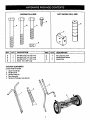
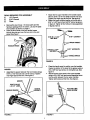
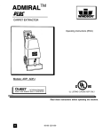
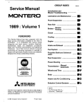
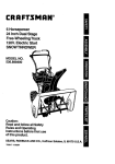
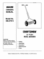
SEARS
OWNERS
MANUAL
Model No.
486.37613
CRAFTSMAN
18" PUSH
REEL MOWER
CAUTION:
Before using this product,
read this manual and follow
all Safety Rules and
OPerating Instructions.
Sears,
Roebuck
•
•
•
•
•
Safety
Assembly
Operation
Maintenance
Parts
and Co., Hoffman
Estates,
IL. 60179
U.S.A.
Safety Rules ............................................................
Warranty ..................................................................
Full Size Hardware Chart ........................................
2
2
3
Assembly .................................................................
Operation ................................................................
Maintenance ............................................................
4
5
6
Storage ....................................................................
6
Service and Adjustments ........................................ 7
Troubleshooting ......................................................
8
Repair Parts Illustration ......................................... 16
Repair Parts List ...................................................
11
Parts Ordering/Service ........................... Back Cover
Any power equipment can cause injury if operated improperly or if the user does not understand
the equipment. Exercise caution at all times, when using power equipment.
•
•
•
•
•
Read the reel mower owner's manual and know
how to operate the reel mower before using it.
Never allow children to operate the reel mower.
Only persons well acquainted with these rules of
safe operation should be allowed to use the
mower.
Keep the area of operation clear of all persons,
particularly small children and pets. Small overlooked objects could be accidently thrown by the
mower.
Thoroughly inspec_tthe area where the mower is to
be used and remove all stones, sticks, wire, bones
and other foreign objects which could be picked up
and thrown by the mower.
Do not operate the mower when barefoot or when
wearing open sandals. Always wear substantial
footwear.
I&
•
•
•
•
•
•
•
how to operate
Mow only in daylight or in good artificial light.
Never operate the mower in wet grass. Always be
sure of your footing. Keep a firm hold on the handle
and walk, never run.
When cleaning, repairing or inspecting the mower,
make sure the blade and all moving parts have
stopped.
Before attempting to unclog the mower, be surethe
blades have stopped completely.
Mow across the face of slopes, never up and down.
Exercise extreme caution when changing direction
on slopes. Do not mow excessively steep slopes.
Keep all nuts, bolts and screws tight to be sure the
equipment is in safe working condition.
Follow all maintenance and lubrication instructions
as outlined in the maintenance section of this
manual.
Look for this symbol to point out important safety precautions.
Become alertll Your safety is involved.
It means--Attention!!
LIMITEDONEYEAR WARRANTYON CRAFTSMAN 18" REEL MOWER
For one year from the date of purchase, when this 18" reel mower is maintained and lubricated according to the
operating and maintenance instructions in the owner's manual, Sears wilt repair any defect in material or workmanship free of charge. If this 18" reel mower is used for commercial or rental purposes, this warranty applies for only 90
days from the date of purchase.
This warranty does not cover repairs necessary because of operator negligence or abuse, including the failure to
maintain the equipment according to instructionscontained in the owner's manual.
WARRANTY SERVICE IS AVAILABLE BY CONTACTING THE NEAREST SEARS SERVICE CENTER/DEPARTMENT IN THE UNITED STATES.
This warranty applies only while this product is in the United States.
This warranty gives you specific legal rights, and you may also have other rights which vary from state to state.
Sears, Roebuck and Co. D/817 WA. Hoffman Estates, Chicago, IL 60179
r
The model and serial numbers will be found on a decal
attached to the
You should record both the serial number and the date of
purchase and keep in a safe place for future reference.
MODELNUMBER:
SERIAL NUMBER:
DATE OF PURCHASE:
486.37613
SHOWN
FULL SIZE
NOT SHOWN
FULL SIZE
E
o
f
jA
I
1
I
I
I
E
I
I
I
I
I
REF.
QTY.
A
B
C
D
1
2
1
2
DESCRIPTION
Hex Bolt, 5/16" x 2-1/2" Long
Hex Bolt, 5/16" x 2-1/4" Long
Hex Bolt, 5/16" x 1-3/4" Long
Screw, #10 x 5/8" Long
REF.
QTY.
E
F
G
4
1
2
DESCRIPTION
Hex Lock Nut, 5/16"
Handle Brace Spacer
Handle Gdp
CARTON
CONTENTS
Loose Parts in Carton
1.
2.
3.
4.
5.
Upper Handle (2)
Handle Panel
Handle Brace (2)
Reel Assembly
Hardware Package ( see above)
4
G
Attach the two upper handles to the handle braCas
with two 5/16" x 2-1/4' hex bolts and 5/16" hex nuts.
Tighten only finger tight at this time. See figure 3.
Fasten the upper handles together at the top with a
5/16" x 1-3/4" hex bolt and a 5/16" Iocknut as shown
In figure 3. Tighten all four bolts and nuts assembled
In figures 2 and 3.
TOOLS REQUIRED FOR ASSEMBLY
(1)
1/2" Wrench
(1)
5/16" Wrench
(1)
Pliers
•
•
Remove the reel mower, the loose parts and the
hardware package from the carton. Lay out the parts
and hardware as shown on page 3.
Insert the short ends of the two handle braces
through the slots and over the two pins in the end
plates. See figure 1.
HANDLE BRACE
FIGURE 3
•
FIGURE 1
•
Assemble the spacer between the two braces using a
5/16" x 2-1/2" hex bolt and a 5/16" Iocknut. Tighten
only finger tight at this time. See figure 2.
•
Place the handle panel in position over the handlas.
Fasten the bottom of the panel to the spacer using a
#10 x 5/8" hex head screw, Do not tighten yet, See
figure 4.
Secure the top of the panel to the upper handles
using a #10 x 5/8" hex head screw assembled down
into the notch between the two upper handles.
Tighten both screws at this time. See figure 4.
SPACER
BOLT 5/16-18
x 2-1/2" LONG
HANDLE BRACES
#10 x 5/8" HEX
HEAD SCREW
5/16-18
LOCKNUT
HANDLE
PANEL
FIGURE 2
FIGURE 4
&
ADJUSTING THE ROLLER
• To adjust the roller, tilt the mower forward and loosen
both the knobs on the roller at least two full turns.
Move the roller to the desired position. Both roller
knobs must be in the same relative position and
tightened until firmly seated in the notches, See
figures 5 and 6.
CAUTION: Mower blades are sharp. Keep
hands and feet clear. Be sure blades are
stopped before approaching near blades.
HOW TO USE YOUR
Cuffing
Height
In Inches
2-1/4
2
1-3/4
1-1/2
1-1/4
1
3/4
REEL MOWER
Both the wheels and the roller are adjustable. By using
combinations of the different wheel and roller settings,
seven different cutting heights are available. The settings
are listed in figure 6.
ADJUSTING THE WHEELS
• Each wheel has a height adjustment lever with five
positions. To move the lever, tilt the mower back on
the roller. Press the levers (one at a time) outward
from the mower and move the lever to the desired
position. Both levers must be in the same relative
position. See figures 5 and 6.
Knob
Lever
4
4
3
2
2
2
2
Wheel
5
4
4
4
3
2
1
WHEEL
ROLLER BRACKET
AUGNMENT HOLE
FIGURE 6
USING YOUR REEL MOWER
•
•
•
WHEEL
LEVER
FIGURE 5
•
•
Adjust the wheels and the roller to the desired height.
Do not attempt to make too deep a cut in tall grass.
Reel mowers work best at a light to moderate depth
of cut.
•
Mow the lawn more frequently, taking a lighter cut to
reduce pushing effort.
Keep blades adjusted and sharpened to improve
smoothness of cut and to reduce pushing effort.
Mow across the face of slopes instead of up and
down slopes for safer footing. Avoid mowing on
excessively steep slopes.
•
•
5
Make sure grass is dry before starting to mow.
Wear substantial footwear which will provide good
traction.
Remove all stones, sticks, wire, bones and other
foreign objects from the area to be mowed. These
objects can either jam the blades or be thrown by the
mower.
CUSTOMER
RESPONSIBILITIES
• Read and follow the maintenance schedule and the
procedures listed in the maintenance section.
MAINTENANCE
SCHEDULE
Fill in dates as you
complete regular service.
Check for loose fasteners
Check for worn or dama_led parts
Clean mower
Lubricate miler, ediustment points
Lubricate wheel bearinas and aears
SCHEDULED
Service Dates
X
X
X
X
X
X
MAINTENANCE
I.
J.
Lubricate the wheel adjustment mechanisms and the
roller with a light oil as shown in figure 7. Periodic
lubrication of these points will help ensure smooth
mechanical operation.
Pull the pawl from the reel shaft and clean.
Reinstall parts in reverse order.
IMPORTANT:
Note the position of the pawl in the shaft
before removal. It must be installed facing the same way
as when it was removed or the wheel will not drive. The
flat surface of the pawl mates against the fiat surfaces of
the teeth inside the pinion gear.
PAWL
PINION
GEAR
FIGURE 7
Clean and lubricate the wheel bearings and gears
once every season or whenever the reel is sharpened, whichever is more often. Refer to figure 8.
A. - Remove the hub cap
B. Remove the E-ring with a screwdriver.
C. Uft off the wheel.
D. If the axle is rusty, clean off with solvent and
crocus cloth.
E. Coat the axle with light grease.
F. Clean the gear teeth on the inside of the wheel
and then apply light grease.
G. Using snap ring pliers, remove the snap ring
from the reel shaft and then remove the pinion
gear. Avoid overstretching the snap ring, which
causes a loss of holding power.
H. Clean gear and apply light grease inside gear.
BEARING_
FIGURE 8
STORAGE
•
•
•
6
OF MOWER
Clean the mower thoroughly using a broom or a brush
to remove grass and dirt. DO NOT use water to clean
the mower.
Coat the mower's cutting blades with grease to
prevent rusting.
Store the mower inside a clean, dry area.
SHARPENING
THE BLADES
•
•
The blades should be sharpened when the mower
will no longer cut satisfactorily without the cutter bar
being adjusted to rub against the reel blades.
CUTTER
To decrease the clearance between the cutter bar
and the blades, loosen the upper nut 1/4 turn and
then tighten the lower nut 1/4 turn. Adjust each side
of the mower equally until a .003" clearance is
obtained. See figure 10.
BAR ADJUSTMENT
CHECKING THE CLEARANCE
•
•
•
•
When the cutter bar is properly adjusted there should
be .003" clearance between the cutter bar and the
reel blades. The blades must not contact the cutter
bar. Clearance may be checked in the following
manner.
Cut some quality .003" thick paper (writing paper or a
magazine page) into strips approximately 2" wide and
6" long. Insert a strip of paper between the cutter bar
and the blades as shown in figure 9. Turn the reel
slowly backwards. The blades should pinch but not
cut the paper. Check the clearance at each end and
in the middle of the cutter bar. The paper should be
held snugly by each blade.
Determine whether the space between the cutter bar
and the blades needs-to be increased or decreased
to obtain the recommended .003" clearance.
If the clearance is determined to be correct but the
mower will not cut grass, then the blades should be
sharpened.
UPPERNUI__
UPPER
TRUNNION
LOWER
Cu3-rER
BAR _
BOLT
FIGURE 10
CHECKING THE ADJUSTED CLEARANCE
• Push the handle of the mower forward and let it rest
on the ground. The roller should be off the ground.
• Insert a strip of quality .003" paper (writing paper or
magazine page) between the cutter bar and blades.
• Turn the reel slowly forward as shown in figure 11.
The paper should be cut cleanly, without the blades
contacting the cutter bar.
• Perform this test at each end and in the middle of the
cutter bar.
FIGURE 9
ADJUSTING
THE CU'I-rER BAR CLEARANCE
IMPORTANT: Adjust only the nuts securing the upper
trunnion; DO NOT adjust the nuts on the lower trunnion.
Refer to figure 10.
• Before adjusting the cutter bar, check to make sure
that all the nuts securing the cutter bar and the
adjustment trunnions are still firmly tightened.
• To increase the clearance between the cutter bar and
the blades, loosen the lower nut 1/4 turn and then
tighten the upper nut 1/4 turn. Adjust each side of the
mower equally until a .003" clearance is obtained.
See figure 10.
J
Y
FIGURE 11
GEAR HOUSING
REPLACEMENT
GEAR
IMPORTANT: The gear housing must be reassembled
properly, according to the following instructions, or
it will result in loose wheels and an early failure of
the pinion and the wheel. Refer to figure 12.
•
•
If the gear housing assembly is removed for service,
it is very important for the gear housing assembly to
fit UNDER the lip of the retainer when reassembled.
The shoulder on the shoulder washer must fit into the
curved slot in the end plate. Tighten the lock nut and
then back it off one half turn so the height adjuster
can move freely.
SHOULDER
WASHER
LOCK NUT
FIGURE 12
PROBLEM
vlower won't cut grass satisfactorily
_rass clogs up the reel blades.
CAUSE
CORRECTION
1. Blades are dull.
1.
2. Too much cutter bar clearance. 2.
Resharpen blades.
Adjust the cutter bar. See page 7,
Service and Adjustments section.
Set mower to a higher cutting height.
Mow grass more often.
3. Grass is too tall.
3.
1. Grass is too wet.
1. Allow grass to dry before mowing.
NOTES
9
56
57
3
55
53
9
54
\
28
48
29
, 11
l
9
27
"\-'_
10
59
30
_f26
62 34
\,
60
40 39
-
16
41
37
36
35
20
lO
17
PARTS LIST FOR MODEL 486.37613
F:tEF. PARTNO.
NO.
1
2
3
4
5
6
7
8
9
10
11
12
13
14
15
16
17
18
19
20
21
22
23
24
25
26
27
28
29
46471
43084
43064
46434
43224
44292
3603-43
2624-018
1108-80
0425-000
2118-082
1609-708
46330
43716
1632-144"
1509-086
2134-14
46331
46329
43512
0455-000
3111-131
1643-023
1609-707
43081
43682
0010-000
44060
1112-029
QTY'.
18 = PUSH REEL MOWER
DESCRIPTION
2
1
4
2
2
1
2
Grip
Bolt, Hex 5/16-18 x 1-3/4" Lg. *
Nut, Hex Lock 5/16-18 Thd. *
Upper Handle
B01t, Hex 5/16-18 x 2-1/4" Lg. *
Bolt, Hex 5/16-18 x 2-1/2" Lg. *
Handle Brace
1
2
1
1
1
2
-1
1
1
1
2
2
8
1
1
2
1
2
2
2
8
1
Spacer
Wheel Assembly
Pinion Gear, R.H.
Gear Housing Assembly. - R.H.
Roller Bracket, R.H.
Trunnion, Adj. Screw
18" Roller
Roller Shaft
Screw, Cutter Bar (L.H. Thd.)
Cutter Bar Assembly
Screw, Adjustment
Trunnion, Adjustment Screw
NUt, Hex 3/8-24 Thd.
Screw, Cutter Bar (R.H. Thd.)
End Plate Assembly. - L.H.
Roller Adjustment Knob
Roller Bracket, L.H.
Flat Washer, 5/16" Std. *
Carriage Bolt, 5/16-18 x 1-1/4"
Trunnion
Pop Rivet
Spacer Tube Assembly.
REF.
NO.
PARTNO.
DTY
30
31
32
33
34
35
36
37
39
44738
1657-019
1038
1509-038
1624-138
0323-000
0428-000
1650-21
1540-118
2
2
2
2
2
2
1
2
2
40
41
44
46
1660-001
2674-032
1534-8
44008
2
2
2
2
47
48
49
50
53
54
55
56
57
59
60
61
62
1631-51
1643-060
1622-050
44232
1629-028
C-9M5732
2135-046
44818
8622-54
3111-130
2118-081
1155-047
1629-041
47312
2
2
2
2
2
6
1
2
1
1
1
2
2
1
* Common hardware may be purchased locally.
11
DESCRIPTION
NUt, Hex Lock 5/16-24 Thd.
Bushing, Wheel Adjust
Hex Lock Nut, 3/8-24 Thd.
Hex Screw, #10-32 x 3/8" Lg.
Retainer
Pawl
Pinion Gear, L.H.
Retaining Ring
Flat Washer, 3/8" I.D. x
1-1/4' O.D.
Retaining Ring
Hub Cap
Hex Lock Nut, #10-32 Thd.
Flat Washer, 1-1/8" O.D. x
.78"1.D. x .025"
Axle
Knob, Wheel Adjustment
Dust Cover
Bearing
Retainer, Bearing
Rivet, Pop
18' Reel Assembly.
Screw, Hex Hd. #10 x 5/8" Lg.
Handle Panel
End Plate Assembly. - R.H.
Gear Housing Assembly. - L.H.
Spring and Trunnion Assembly
Pinion Housing
Owners Manual
For the repair or replacement ,partsyou
need delivered directly to your home
Call 7 am -7 pro, 7 days a week
1-800-366-PART
(1-800-366-7278)
For in-home major brand repair service
Call 24 hours a day, 7 days a week
1-800-4-REPAIR
(1-800-473-7247)
For the location of a Sears Parts
and Repair Center in your area
Call 24 hours a day, 7 days a week
1-800-488-1222
For information on purchasing a Sears
Maintenance Agreement or to inquire
about an existing Agreement
Call, 9 am - 5 pm, Monday-Saturday
1-800-827-6655
When requesting service or ordering parts,
always provide the following information:
• Product Name
° Part Name
• Model Number
° Part Number
PRINTED IN USA
8F_/ 8
America's
Repair
Specialists
FORM NO. 47312 (2/98)