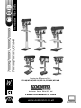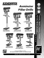
1
Axminster
Pillar Drills
700091 WD16B
Bench Pillar Drill
700100 ED16B2
Bench Pillar Drill
User Manual
700090,700091,700092,700099
700100,700101,951645
700092 WD16F
Floor Pillar Drill
700101 ED16SB
Bench Pillar Drill
700090 WD13S
700099 WD13L
Bench Pillar Drills
951645 WD16SB
Bench Pillar Drill
Axminster Reference No’s:
WD16B, WD16F, WD13S, WD13L, ED16B2, WD16SB
www.axminster.co.uk
W
AXMINSTER
W H I T E
Index of Contents
Page No.
Index of Contents.............................................................................................................................................. 2
Declaration of Conformity………….………........……..…………................................................................. ..2
What’s in the Box………….………........……..…………..................................................................................... 3
General Safety Instructions Mains Equipment.............................................................................4-5
Initial Assembly Instructions........................................................................................................ 5-6
Specifications….………........……..…………................................................................................................7-8
Identification and Description of the Drill Press................................................................... 9-11-13
Machine Illustration of the Drill Press............................................................................ 10-12-14-15
Changing Speed............................................................................................................................ 16
Speed Select Table........................................................................................................................ 17
General Safety Instructions for Drilling Machines........................................................................ 18
Maintenance................................................................................................................................... 19
Illustrated Parts Beakdown..................................................................................................20-23-25
Illustrated Parts List........................................................................................................ 21-22-24-26
Notes...............................................................................................................................................27
Declaration of Conformity
The undersigned,
authorised by Laizhou Light Industry Machinery Plant
No. 989 Laizhou North Road, Laizhou, Shandong
261400, China
declares that this product:
Copied from CE Certificate
ZQJ4119-3
Drill Press
The undersigned,
manufactured by Laizhou Light Industry Machinery Plant is in
compliance with the following standards or standardisation
documents in accordance with Council Directives
DIN EN 60204-1:1998-11
Machinery Directive 98/37/EEC, Annex 1
Amended 93/68/EEC
authorised by Shandong Laizhou Light Industry Machinery Plant
No. 989, North Lai Zhou Road Laizhou,
Shandong 261400 P. R. China
declares that this product
ZQJ4116Q
Drill Press
manufactured by Shandong Laizhou Light Industry Machinery Plant is
in compliance with the following standards or standardisation
documents in accordance with Council Directives
The undersigned,
authorised by Laizhou Plant Machinery Co., Ltd
989 North Lasi Zhou Road Laizhou, Shandong
declares that this product:
ZQJ4113,ZQJ4119K
Drill Press
manufactured by Laizhou Plant Machinery Co. is in
compliance with the following standards or standardisation
documents in accordance with Council Directives
02
EN 55014-1: 1993+A1
EN 61000-3-2: 1995+A13
EN 61000-3-3: 1995
EN 55014-2: 1997
What’s in the Box?
Quantity
1 No.
1 No.
1 No.
Item
Axminster Medium Engineers Drill Press
Base
Drill Pillar complete with Mounting Flange,
Rise and Fall Rack and Rack Retaining Ring
Drill Table Mounting Bracket
Drill Table
Tri- Lever Feed Handle
Drill Guard
Model Number
ZQJ4119-3
ZQJ4113,ZQJ4119K
ZQJ4116Q
I No.
1 No.
1 No.
1 No.
1 No. Pkt containing:4 No.
M10 x 25mm Hexhead Bolts and M10 Spring and Plain Washers
1 No.
6mm Allen Key
1 No.
5mm Allen Key
1 No.
3mm Allen Key
1 No. Pkt containing:1 No.
Windlass Handle for Table Rise and Fall Mechanism
1 No.
Drill Taper Arbor for the Chuck
1 No.
Break Taper Drift
1 No.
Box Containing 3-16mm B16 Keyless Chuck
1 No.
Box Containing 13mm B16 Keyless Chuck
1 No.
Manual
1 No.
Guarantee Card
Having unpacked your machine and its accessories, please check the contents against the
equipment list ”What’s in the box”, if there are any discrepancies, please contact Axminster
Power Tool Centre using the procedures laid down in the catalogue. Please dispose of the
packaging responsibly; much of the material is bio-degradable. The machine and its accessories
will arrive coated with heavy corrosion preventative grease and greased wax paper or plastic
wrapping. These will need to be cleaned from the machine, its components and accessories prior
to it being set up and commissioned. Use paraffin or a proprietary degreaser to remove the
barrier grease. Be warned, it will stain if you splash it on clothing etc.; wear overalls, coverall et
al., rubber gloves are also a good idea, as is eye protection if your cleaning process tends to be
a little bit enthusiastic. After cleaning, lightly coat the exposed metal surfaces of the machine
with a thin layer of light machine oil. N.B If you used paraffin/kerosene make sure you apply this
thin film sooner rather than later.
Please read the Instruction Manual prior to using your new machine; as well as
the installation procedure, there are daily and periodic maintenance
recommendations to help you keep your machine on top line and prolong its life. Keep
this Instruction Manual readily accessible for any others who may also be required to
use the machine.
!
03
General Safety Instructions Mains Equipment
Work Place/Environment/Installation
Mains Powered Machines
Primary Precautions
These machines are supplied with a moulded 13 Amp. Plug and 3 core power cable. Before
using the machine inspect the cable and the plug to make sure that neither are damaged. If any
damage is visible have the machine inspected/repaired by a suitably qualified person. If it is
necessary to replace the plug, it is preferable to use an ‘unbreakable’ type that will resist
damage. Only use a 13 Amp plug, make sure the cable clamp is tightened securely. Fuse at 13
Amp. If extension leads are to be used, carry out the same safety checks on them, and ensure
that they are correctly rated to safely supply the current that is required for your machine. It is
also recommended that the power supply outlet is the switched type, and that the supply is
switched off whilst plugging in, or unplugging the machine.
General Instructions for 240v Tools
Good Working Practices/Safety
The following suggestions will enable you to observe good working practices, keep yourself and
fellow workers safe and maintain your tools and equipment in good working order.
!
WARNING!! KEEP TOOLS AND EQUIPMENT OUT OF THE REACH OF YOUNG
CHILDREN
Work Place/Environment
The machine is not designed for sub-aqua operation, do not use when or where it is liable to get
wet. If the machine is to be used outside and it starts to rain (unusual though this would be in
U.K.), stop work and move it inside. If machine has got wet; dry it off as soon as possible, with a
cloth or paper towel. Do not use 240Va.c. powered machines anywhere within a site area that is
flooded or puddled, and do not trail extension cables across wet areas. Keep the machine clean;
it will enable you to more easily see any damage that may have occurred. Clean the machine with
a damp soapy cloth if needs be, do not use any solvents or cleaners, as these may cause
damage to any plastic parts or to the electrical components.
Keep the work area as uncluttered as is practical, this includes personnel as well as material.
!
(Under no circumstances should CHILDREN be allowed in work areas)
It is good practice to leave the machine unplugged until work is about to commence, also make
sure to unplug the machine when it is not in use, or unattended. Always disconnect by pulling on
the plug body and not the cable. Once you are ready to commence work, remove any tools used
in the setting operations (if any) and place safely out of the way. Re-connect the machine. Carry
out a final check e.g. check the cutting tool, drill bit, saw blade etc., is securely tightened in the
machine, check you have the correct speed and function set, check that the power cable will not
‘snag’ etc. Make sure you are comfortable before you start work, balanced, not reaching etc. If
the work you are carrying out is liable to generate flying grit, dust or chips, wear the
appropriate safety clothing, goggles, gloves, masks etc., If the work operation appears to be
excessively noisy, wear ear-defenders. If you wear your hair in a long style, wearing a cap, safety
helmet, hairnet, even a sweatband, will minimise the possibility of your hair being caught up in
the rotating parts of the machine, likewise, consideration should be given to the removal of rings
and wristwatches, if these are liable to be a ‘snag’ hazard. Consideration should also be given to
non-slip footwear, etc.
04
General Safety Instructions Mains Equipment (Contiued)
DO NOT work with cutting or boring tools of any description if you are tired, your attention is
wandering or you are being subjected to distraction. A deep cut, a lost fingertip or worse; is not
worth it!
DO NOT use this machine within the designated safety areas of flammable liquid stores or in
areas where there may be volatile gases. There are very expensive, very specialised machines for
working in these areas, THIS IS NOT ONE OF THEM.
CHECK that cutters, drills, blades etc., are the correct type and size, are undamaged and are
kept clean and sharp, this will maintain their operating performance and lessen the loading on
the machine.
Above all, OBSERVE…. make sure you know what is happening around you, and USE YOUR
COMMON SENSE.
Initial Assembly Instructions
INITIAL ASSEMBLY FOR: WD16B,WD16F, ED16B2, ED16SB, WD16SB
Please read through the section entitled Identification and Description of Parts, so that
you will be familiar with the terminology we will use in the manual, so that you can
identify the parts quickly and easily and initial assembly will go smoothly.
!
WARNING The drillhead is a heavy and substantial piece of
machinery, you are advised to have help to lift it clear of the box
and fit it to the column.
Place the base in a convenient position (on the bench?) and place the mounting flange of the
column onto the seating flange of the base. Align the holes. Use the 4 No. M10 x 25mm and the
10mm spring and plain washers and secure the column to the base. Loosen the socket
grubscrew holding the cup chamfered retaining collar to the column (with the supplied allen key),
remove it and the rise and fall rack, put aside. Take the drill table mounting bracket arm and twist
the worm drive shaft with your fingers such that the whole shaft protrudes from the casting and
the worm gear itself is clear of the square recess in the main body of the casting. Locate and fit
the crank handle to the shaft, ensuring that you tighten the grub screw onto the machined flat on
the shaft. This will keep the worm gear in position. Pick up the rise and fall gear rack, identify the
top and the bottom, (the rack gearing is cut asymmetrically, with the gear cut extending closer to
the bottom), make sure you have the rack the right way up, as it will allow you to drive the drill
table up and down over its full range. Fit the rise and fall rack into the square recess in the
mounting body casting, ensure that it is engaged with the pinion, and lower the combined
mechanism over the column.
Allow it to slide down the column until the rise and fall rack is located in the cup chamfer in the
top of the mounting flange. Replace the cup chamfered retaining collar over the column and slide
it down onto the top of the rack. Lock it in place with the grubscrew, ensuring that it has captured
the upper end of the rack securely, but not too tight that the rack can not be swivelled around the
pillar. Check that the bracket can be driven up and down the column and can swivel around the
pillar. Locate the Bristol clamping handle at the rear of the bracket and tighten, check it has
‘pinched’ up on the column and the bracket is immobile; both in it’s up and down travel and
swivel movement.
Fit the drill table, identify the Bristol clamping handle at the front of the bracket and tighten,
check it has ‘pinched’ up on the drill table spigot and the drill table is immobile. So far so good!
Now comes the heavy lift bit.
05
Initial Assembly Instructions (Continued)
CHECK the drillhead, ensure that the two hex socket grubscrews that lock the head in place on
the column are withdrawn and will not foul on the column when the head is fitted. Put the lower
assembly you have just been working on in the most convenient position, make sure it is stable
and lift the drillhead over the column and let it drop into place. The column does not ‘come
through’ the drillhead, so you don’t have to worry about holding the drillhead in place whilst
frantically trying to lock it in place. Set the drill head approximately fore and aft and lock in
postion using the two caphead grub screws mentioned earlier. Check that the drillhead is
immobile. Everything on the drilling m/c is now secured, and if you now wish to move it to its
referred workplace, nothing should slew during the lift and move. Once the drilling machine is
correctly positioned and, if necessary, fastened down; you can proceed with the final assembly.
Locate the tri-lever feed handle and its securing screw, note the raised boss of the feed
mechanism and the spigot next to it. Mount the handle over the boss and ensure the spigot hole
in the handle engages the spigot on the mechanism. Secure with the supplied caphead bolt
through the hole in the centre of the handle through to the tapped hole in the mounting boss.
Take the chuck guard and fit to the lower bearing flange of the quill mounting. Tighten the screw
and nut fastening so that the drill guard is securely held in place. Congratulations, one
assembled pillar drill!
INITIAL ASSEMBLY FOR: WD13S & WD13L
Base/Column Assembly
Place the base in a convenient position (on the bench?) and place the mounting flange of the
column onto the seating flange of the base. Align the holes. Use the 3 No. M8 x 20mm and the
8mm plain washers and secure the column to the base with a 13mm spanner.
Table Assembly
Locate the table/support assembly and slide it down the column until it rests on the base plate.
Insert the locking clamp lever into the treaded hole to the side of the table casting, slide the table
up the column to working height and clamp the table in position.
Drillhead Assembly
CAUTION: The drillhead is heavy, we recommend you seek assistance.
Using the 3mm allen key loosen the two grub screws to the right side of the head, lift the
drillhead above the column and let it drop into place. The column does not ‘come through’ the
drillhead, so you don’t have to worry about holding the drillhead in place whilst frantically trying
to lock it in place. Set the drillhead approximately fore and aft and lock in postion using the two
caphead grub screws mentioned earlier. Check that the drillhead is immobile. Everything on the
drilling m/c is now secured, and if you now wish to move it to its preferred workplace, nothing
should slew during the lift and move. Once the drilling machine is correctly positioned and
fastened down, it is ready for use.
06
Specifications
Model
ED16B2
ED16SB
WD16SB
700101
Hobby
370W
(5) 460-2890rpm
60mm
127mm
315mm
430mm
951645
Hobby
370W
(5) 460-2890rpm
60mm
127mm
315mm
430mm
Axminster Medium Pillar Drill
Rating
Motor 240V 50Hz
Speed Range (12)
Column Diameter
Throat
Chuck to Table
Chuck to Base
700100
Trade
650W
120-2580rpm
80mm
178mm
310mm
510mm
Head Turn, Table Turn, Table Swivel
Table Tilt
Table Size
Table Fixing
Quill Mandrel
Chuck Capacity/type
Chuck Travel
Machine Lamp (Fixed Integral)
360˚
45˚-0-45˚
290 x 290mm
Four No ‘T’ Slots
MT2
3-16mm Keyless
80mm
</= 40W Edison
Screw Bulb
450 x 270mm
710 x 350 x 1015mm
82kg
Base Size
Overall Size L x W x H
Weight
360˚
45˚-0-45˚
200 x 200mm
Four No ‘T’ Slots
MT2
16mm Keyless
60mm
Not Fitted
360˚
45˚-0-45˚
200 x 200mm
Four No ‘T’ Slots
MT2
16mm Keyless
60mm
Not Fitted
340 x 210mm
310 x 520 x 840mm
37kg
340 x 210mm
310 x 520 x 840mm
37kg
07
Specifications
Model
WD16B
WD16F
Axminster Medium Pillar Drilll
Rating
Motor 240V 50Hz
Speed Range (12)
Column Diameter
Throat
Chuck to Table
Chuck to Base
Chuck to Table
Chuck to Base
Head Turn, Table Turn, Table Swivel
Table Tilt
Table Size
Table Fixing
Quill Mandrel
Chuck Capacity/type
Chuck Travel
Machine Lamp (Fixed Integral)
700091
Trade
550W
210-2580rpm
80mm
178mm
310mm
510mm
700092
700090/700099
Trade
Hobby
550W
250W
120-2580rpm
(5) 600-2500rpm
80mm
46mm
178mm
105mm
680mm
WD13S 126mm
1170mm
WD13S 280mm
WD13L 215mm
WD13L 370mm
360˚
360˚
45˚-0-45˚
45˚-0-45˚
310 x 310mm
160 x 160mm
Four No ‘T’ Slots
Four No ‘T’ Slots
MT2
B16
3-16mm Keyless
13mm Keyless
80mm
50mm
</= 40W Edison
Not Fitted
Screw Bulb
450 x 270mm
290 x180mm
710 x 350 x 1645mm (700090 WD13S)
Base Size
Overall Size L x W x H
Weight
08
360˚
45˚-0-45˚
310 x 310mm
Four No ‘T’ Slots
MT2
3-16mm Keyless
80mm
</= 40W Edison
Screw Bulb
450 x 270mm
710 x 350 x 1015mm
80kg
88kg
WD13S/WD13L
240 x 470 x 600mm
(700099 WD13L)
240 x 470 x 735mm
19kg (WD13S)
26kg (WD13L)
Identification and Description of the Drill Press
Base casting
(See fig 1)
This is the ‘Stand’ for the drilling m/c . It has a seating flange to the rear,
which has 4 No. M10 tapped holes in the face to bolt down the column flange.
There are 4 No. 12mm holes in the approximate corners of the base to enable
it to be bolted to the bench or the floor depending upon the model you have
purchased. There are also 2 No. slots machined in the base to enable the
fastening of a machine vice or similar, if a greater working depth is needed
than that available above the table.
Drill column
(See fig 1)
This is the ‘pillar’ of the drill, it is an 80mm diameter steel tube 800mm
long. The column is fitted into a mounting flange at the lower end. This flange
has four holes bored in it to correspond to the four tapped holes in the base
casting. The pillar is normally supplied with the rise and fall rack for the
drilling table fitted. The rise and fall rack is held in place between the cup
chamfer in the mounting flange and a cup chamfered retaining collar that
slides over the pillar and is held in position by a locking grubscrew.
Drill table
mounting
bracket
(See fig 1)
(See fig 1c)
(See fig 1d)
This is a cast bracket that fits over the column, it has a worm driven pinion
that engages with the rise and fall rack and allows the bracket to be driven up
and down on the column. The worm is turned by a windlass type crank
handle. The rear of the casting is split and has two lugs, one bored thro’
clearance for the locking clamp lever handle, and the other with a
corresponding tapped hole to allow the Bristol lever clamping handle to draw
the casting together and ‘pinch’ onto the column and lock the bracket in
place. Bolted to the front of the bracket is the drill table mounting. This
casting has a hole machined through it to accept the spigot of the drilling
table. The casting is split similarly to the main casting with a similar clamping
lever handle, which ‘pinches’ the casting around the drill table spigot to lock it
in position. If the bolt, holding the two parts of the mounting bracket together
is loosened, the drill table mounting can be tilted to enable drilling at an
angle. There is a graduated scale and a pointer to enable the tilt angle to be
read. Retighten the bolt when the desired angle has been set.
Drill table
(See fig 1)
The drill table is a machined casting 288mm square, with a central spigot that
fits into the table mounting. The main land of the table is surrounded by a
well, so that a recycling coolant system could be fitted. There are 4 radial ‘T’
slots cut into the main land of the table to facilitate the fixing of machine vices
or clamps.
Drillhead
This is the ‘drilling machine’ and the descriptions of its various parts
and components are detailed as follows:-
Pulley and drive A pressed steel cover hinged on one side and secured with a machine screw
Belt Cover
on the other. It covers the drive belt train for safety during normal operation.
(See fig 2)
There is a microswitch fitted between the cover and the lower tray which will
prevent the machine running if the cover is not lowered.
Pulleys and
There are three pulley towers in the drillhead, the drive pulleys fixed to the
drive belts
motor shaft, the driven pulleys fitted to the quill, and the intermediate ‘jockey’
(See figs 2 a ,b,c) pulleys that connect the ‘train’ together with the two drive belts. A total of 12
speeds are available using the various belt positions on the pulleys. (See the
chart on the machine or later in this manual.
09
Machine Illustration of the Drill Press
Fig 1b
Fig 1a
Fig 1
On/Off switch
shroud
On/ Off
switches
Release screw
Motor
Tri-lever feed
handle
Keyless chuck
Drill column
Drill table
Clamping
lever handle
Rack retaining
collar
Drill table mounting
Crank handle
Drill table mounting bracket
Fig 1c
Rise & fall rack
Flange
Fig 1d
10
Mounting bracket bolt
Base casting
Identification and Description of the Drill Press
Release Screw
(See fig 1)
A machine screw that drives through the pulley and drive belt cover into a
tapped hole in a lug on the lower tray. It needs to be unscrewed and removed
to release the top cover for access to the drive belt train. Lower the top cover
and replace the screw when the new speed has been selected.
Safety
micro-switch
(See fig 2c)
The microswitch is the ‘positive plunger’ activated type, and will prevent the
machine from running if the top cover and the lower tray are not closed
together.
Head locking
screws
(See fig 2d)
These are two Hex. Socket grubscrews tapped through the wall of the column
pocket in the drillhead casting. They should be loosened to allow the drill
head to pivot about the pillar. When the required position is achieved,
re-tighten them to lock the drillhead in position. The machine should not be
operated with the drillhead in the unlocked state.
Motor
(See fig 1)
Standard 240V 50Hz single phase motor rated at 250,370,550,560 & 650W
Motor mounting The motor is mounted on a yoke, formed by a mounting plate and two bars
yoke
which also act as part of the tensioning system for the drive belt train. The
(See fig 2d)
yoke is mounted, via the bars, into two tunnel housings in the main body of
the drillhead.
Drive belt
This lever is used to force the motor yoke mounting back against the drive
tensioning lever belt train in order to tension it. The tensioning in the drive belt train is
(See fig 3a)
achieved by the motor pulley pulling on the jockey pulley,(via its belt) and the
jockey pulling on the quill pulley (via its belt). It is good practice to release the
tension in the drive belt train, if the machine is not going to be used for any
lengthy period.
Motor yoke
locks
(See fig 2d)
These ‘T’ bolts are fitted in holes tapped through the walls of the tunnel
housings in the drillhead that fit the motor yoke mounting bars. When the
motor has been forced back to give sufficient tension to the drive belt train
these bolts are tightened up and ‘pinch’ the motor yoke bars and lock the
motor mounting in position.
Tri-lever feed
handle
(See fig 1)
Three levered handle that is used to drive the quill (and hence the chuck) up
and down. The boss of the handle is fitted to a mounting boss on the end of a
‘splined’ gear shaft, it is held in location on the mounting boss by spigot/
spigot hole arrangement. The ‘splined’ gear shaft is, in turn, engaged in the
rack cut into the quill body. The other end of the ‘splined’ shaft is mounted in
a bearing pocket in the back of the positive depth stop assembly. Behind the
mounting boss on the shaft is a contra-wound spring, this provides counter
balance to the weight of the quill, arbor, chuck and drill, giving a more
controlled ‘feel’ during drilling operations. It also retracts the quill when
drilling is completed.
11
Machine Illustration of the Drill Press
Quill Pulley
Jockey pulley
Fig 2a
Fig 2b
Speed select table
Drive pulley
Safety
micro-switch
Fig 2c
Pulley and
drive belt
cover
Pulley and
drive belts
Fig 2
Motor
Motor yoke
lock
Head locking
screws
Motor mounting
yoke
Fig 2d
12
Identification and Description of the Drill Press
Positive depth
Stop
(See fig 3b)
This is a combination of a cast angle bracket & cover, which fits in a housing
machined in the drillhead, (it mounts the bearing pocket for the end of
the splined feed shaft and the return spring), the ‘angle arm’ of the bracket
protudes out from the drillhead parallel with the base. There is a clearance
hole bored through this arm. There is a round plate casting with a triangular
extrusion clamped around the outer sleeve of the quill. Within the apex of this
triangle a threaded hole mounts the depth stop control rod, which also feeds
up through the clearance hole in the angle arm bracket. This rod is originally
threaded, which allows it to be screwed through the hole in the plate and
secured in position with a lock nut. The greater part of the rod over the top of
the mounting plate has been milled flat (less than radius depth) to enable a
scale decal to be fitted. A nut is fitted over to the depth stop rod below the
angle arm bracket (to control the ‘lift’ of the quill) and a nut and a lock nut
fitted above the angle arm bracket to limit the ‘plunge’. The graduated scale
can be read over the top of the angle arm bracket and will allow the depth of
the drill plunge to be measured, or set.
Machine light
(See fig 3d & e)
An Edison screw lamp holder is mounted inside the Drill head, this will light
the drill tip area from behind. The lamp is controlled by a small rocker switch
mounted on the front of the drillhead.
On/Off switch
(See fig 1a & b)
An NVR switch panel mounted on the front of the machine. Green ‘I’ will start
the machine; red ‘O’ to stop. Should power be interrupted whilst the machine
is in use, the NVR will ensure the machine has not remained in the switched
on condition when power is restored. The switch assembly is fitted with a
moulded hinged shroud. This shroud has to be lifted to allow access to the
On/Off switches. On the inside of the shroud is a moulded protrusion that
depresses the Off button, this precludes the machine being switched on if the
shroud is closed. There is the facility to clip the shroud closed, and the
addition of a small padlock could render the machine secure from ‘fiddling
fingers’. The outside of the shroud has a large moulded ‘mushroom’ knob,
which, in an emergency can enable the shroud to be ‘slapped’ closed, and
the machine switched off quickly.
Speed select
table
(See fig 2)
A small chart, which shows the pulley and belt configurations required to
attain the various speeds available on the machine. It is stuck inside the top
of the pulley and drive belt cover.
Quill lower
bearing flange
(See fig 3f)
The quill lower bearing housing is extruded below the base line of the
drillhead and formed into a circular flange in order to mount the chuck guard.
Chuck
(See fig 3g)
A good quality 3-16mm keyless chuck. It is fitted to the quill mandrel using a
MT2/B16 arbor.
Chuck guard
(See fig 3g)
A hinged and telescopic guard that is fitted to the quill lower bearing flange. It
has a spring fitted to the hinge geometry to hold the guard “over centre” to
maintain it in the raised or lowered position. The guard shield can be
extended or retracted (telescoped) as required, using the second leaf, the
second leaf is held in position by two butterfly nuts and bolts.
13
Machine Illustration of the Drill Press
Motor yoke lock
Drive belt
tensioning lever
Machine light switch
NOT FITTED TO
(ED16SB/WD13S/WD13L)
Fig 3d
Drill head
Fig 3a
NOT FITTED TO
ED16SB/WD13S/WD13L
Fig 3e
Depth stop
control rod
Machine light
Guard removed for clarity
Fig 3f
Locking
clamp lever
Fig 3b
Postive depth stop
assembly
Quill lower
bearing flange
Pointer
Chuck guard
Fig 3
Fig 3c
Table tilt scale
14
Fig 3g
Keyless chuck
Machine Illustration of the Drill Press
WD13S & WD13L ILLUSTRATIONS
Fig 4b
Micro switch
Speed select table
Fig 4a
Quill pulley
Drive pulley
Tri-lever feed handle
Release screw
On/Off switch shroud
Motor mounting yoke
Keyless chuck/guard
Motor tension spring
Drill column
Fig 4c
Drill table
Fig 4
Base casting
Flange
Head locking screws
Motor yoke/belt
tension lock
15
Changing Speed
Switch the machine off. Switch off the supply, and/or disconnect the machine from the supply.
Remove the securing screw from the off side of the pulley and drive belt cover, put carefully aside
and raise the cover clear. Now is a good time to give the drive belt and pulley enclosure a good
clean. ( If it needs it? There are sometimes rubbings from the belts and general dust and debris.)
Locate and loosen the motor yoke locks. Locate the drive belt tensioning lever and turn it
clockwise, to move the motor yoke mounting “in” (See fig 5a & 5c). This should have removed
the tension from the drive belts. To release the tension on (ED16SB & WD16SB) loosen the two
motor yoke locks on either side of drilllhead, push the motor assembly up against the drillhead
casting, thus allowing the jockey pulley to pivot. To release the tention on (WD13S,WD13L)
loosen the motor yoke/belt tensioning lock which loosens the tension spring, then push the
motor up against the drillhead casting. (See fig 4,4a & 4c) Refer to the Speed Select Table and
ascertain the belt positions for the speed you require. Move the belt/s to these positions,
commence the tensioning operation by pushing the jockey pulleys to tension the driven to jockey
belt (Have a care not to trap fingers, the pulleys are free to move). Tension the whole belt train by
turning the drive belt tensioning lever anti-clockwise, to move the motor yoke mounting “out”
(See fig 5b & 5d). Keeping the belt train under tension; tighten the motor yoke locks. Lower the
belt and pulley cover carefully, (remember the microswitch) refit the securing screw and tighten.
Re-connect the supply and switch on. Check the drill runs smoothly, no hard vibration, no
squeaks or squeals of loose belts etc., etc., If all seems satisfactory, recommence drilling
operations.
Fig 5
Fig 5a
Fig 5b
Anti-clockwise
Clockwise
Step 1
16
Drive belt tensioning lever
Step 2
Motor mounting yoke “IN”
Motor mounting yoke “OUT”
Fig 5c
Fig 5d
Speed Select Table
SPEED TABLE FOR: WD16B,WD16F, ED16B2, ED16SB
SPEED TABLE FOR: ED16SB & WD16SB
SPEED TABLE FOR: WD13S & WD13L
17
General Safety Instructions for Drilling Machines
1. Do not operate the machine without carrying out a preliminary inspection.
2. Check that the speed is correct for the planned operation, and the upper drive belt cover is
closed and fastened secure.
3. Check the drill bit is the correct size and type, is correctly fitted and tightened in the chuck.
4. Make sure that the drillhead, the table bracket arm, the table tilt and the table swivel clamps
are all locked before any drilling is attempted.
5. Do not attempt to carry out any drilling operation on material that has not been secured to the
drill table, either by vise or clamp.
6. Remove any tools (chuck key, spanners etc), that may have been used in setting up operations
and put them away in their correct stowage positions.
7. Try to arrange the drilling operation so that the drill tip does not come in contact with the table.
8. Always allow the drill to stop before removing drillings or swarf from around the job or the
table.
9. NEVER remove ‘flying’ swarf strands from the drill whilst it is turning.
10. It is a good precaution to wear eye protection when drilling, especially using small drills, or
very hard material that produces small chips.
11. It is not a good idea to wear gloves when operating a drill press.
12. After the job is completed, remove all tools and accessories from the machine, check that
drill bits are still sharp and re-useable. Clean the machine down thoroughly, including removing
coolant or cutting compounds from the drill table. Lightly coat all metal surfaces with a light oil
coating. Disconnect the machine from the supply. Secure the cable/plug clear of the floor.
18
Maintenance
Excessive dust in the motor can cause excessive heat to develop. Every effort should be made to
prevent foreign material from entering the motor. When operated under conditions likely to permit
accumulations of dust, dirt or waste, a visual inspection should be made at frequent intervals.
Accumulations of dry dust can usually be blown out successfully.
Caution: To avoid eye injury or adverse reaction to dust, high pressure hoses should
not be used especially in poorly ventilated areas. The operator performing this cleaning
function should wear safety goggles and dust filter mask.
After cleaning all dust and debris a light coating of machine oil on the quill then to spread the oil.
If the machine is going to stand idle for any length of time, a light coat of spray or machine oil
over the column and table will prevent rusting.
!
DO NOT USE THE MACHINE IF THE POWER CABLE HAS BECOME DAMAGED.
If any servicing (other than the above cleaning) becomes necessary the unit should be returned
to your supplier or repaired by a qualified electrician.
N.B. The speed of the motor cannot be regulated or changed - no adjustment is necessary.
Oil
OIL
19
Illustrated Parts Beakdown
700091-WD16B
700092-WD16F
700100-ED16B2
20
Please Note: Some parts of
the drawing below are
mirrored for clarity
Illustrated Parts List
Ref
Ref
No
Description Unit
QTY No
Description Unit
QTY
1
BASE
1
33
SCREW SPECIAL SET
1
2
COLUMN SHOULDER
1
34
SHIFTER BAR
1
3
RACK
1
35
C-CLIP
1
4
COLUMN
1
36
SLIDE BAR BOLT
2
5
HEX BOLT
4
37
SLIDE BAR
1
6
SCREW
2
38
SLIDE BAR
1
7
MARK
1
39
WASHER
2
8
TABLE BRACKET
1
40
MOTOR BASE
2
9
CLAMP BOLT
1
41
NUT
2
10
WORM GEAR
1
42
MOTOR PULLEY
1
11
SHAFT
1
43
V-BELT
1
12
HANDLE
1
44
PULLEY COVER
1
13
GEAR
1
45
SET SCREW
1
14
RACK RING
4
46
MOTOR
1
15
SET SCREW
1
47
KEY
1
16
TABLE
1
48
NUT
4
17
TABLE BOLT
1
49
WASHER
4
18
TABLE ARM BRACKET
1
50
HEX BOLT
4
19
HEX BOLT
2
51
BODY
1
20
PIN
1
52
CENTER SHAFT
1
21
MARK
1
53
C-CLIP
1
22
SCREW
2
54
BALL BEARING
1
23
WRENCH 5mm
1
55
CENTER PULLEY
1
24
WRENCH 3mm
1
56
C-CLIP
1
25
POWER CORD
1
57
SCREW
1
26
SCREW
3
58
KNOB
1
27
COVER
1
59
WASHER
1
28
NUT
2
60
SPEED CHART LABEL
1
29
SPRING CAP
1
61
SCREW
4
30
TORSION SPRING
1
62
WASHER
4
31
SPRING COVER
1
63
HEX BOLT
1
32
NUT
1
64
SHIFTER
1
21
Illustrated Parts LIst
Ref
Ref
No
Description Unit
QTY No
Description Unit
QTY
65
SET SCREW
1
97
NUT
1
66
SET SCREW
1
98
C--CLIP
1
67
SET SCREW
2
99
BALL BEARING
1
68
DEPTH RING
1
100
SPACER
1
69
FEED SHAFT
1
101
BALL BEARING
1
70
HANDLE
1
102
INSERT PULLEY
1
71
HANDLE COVER
1
103
SPINDLE PULLEY
72
CAP BOLT
1
104
PULLEY NUT
1
73
V-BELT
1
105
NUT
1
74
SCREW
2
106
LIGHT BODY
1
75
SWITCH BOX
1
107
LIGHT BASE
1
76
SCREW
2
108
SCREW
1
77
WASHER
2
109
LIGHT SCREW
1
78
WASHER
1
79
SCREW
2
80
SWITCH
1
81
NUT
3
82
SCREW
2
83
SCALE
1
84
SCALE BASE
1
85
C--CLIP
1
86
BALL BEARING
1
87
RUBBER WASHER
1
88
SPINDLE SLEEVE
1
89
WEDGE
1
90
BALL BEARING
1
91
CAP BOLT
1
92
PLATE
1
93
SPINDLE
1
94
ARBOR
1
95
CHUCK
1
96
CHUCK KEY
1
22
Illustrated Parts Beakdown
700090-700099 (WD13S & WD13L)
23
Illustrated Parts List
700090-700099 (WD13S & WD13L)
24
Illustrated Parts Beakdown
700101 (ED16SB)
951645 (WD16SB)
25
Illustrated Parts List
700101-951645 (ED16SB & WD16SB)
26
Notes
27
Pillar Drills
700090,700091,700092,700099
700100,700101,951645
Axminster
Axminster Reference No’s:
W
WD16B, WD16F, WD13S, WD13L, ED16B2, WD16SB
AXMINSTER
W H I T E
Axminster Devon EX13 5PH UK
FREEPHONE 0800 371822
www.axminster.co.uk