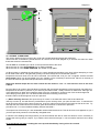
1
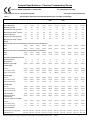
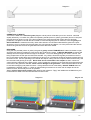
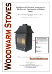
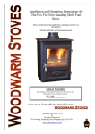
Installation and Operating Instructions for
The Fireview Free Standing Multi Fuel
Range.
Please read this booklet thoroughly before attempting to install or use
this appliance.
Includes Registration and Guarantee Document.
Serial Number
Also detailed on data plate located on the
back of the stove
Please quote when making an enquiry
M____:______
Boiler :______
Canopy:______
A new era in clean, effective multi-fuel stoves.
Woodwarm Stoves
Woodwarm Stoves (Est. 1974)
By
Metal Developments Ltd
The Workshop, Wheatcroft Farm, Cullompton, Devon EX15 1RA
Tel : 01884 35806 Fax : 01884 35505
www.woodwarmstoves.co.uk
1
List of Contents
General Specifications
Page 3
Cautionary Notes on Use
Page 4
Regulations and Installation Instructions
Hearth
Stove Site and Minimum Clearances
Chimney and Flue
Air Ventilation and Free Air
Flue Appliance Outlet Positions
Flue Outlet Configuration
Installing the Stove
Baffle
Internal Fireboards
Fire Doors
Glass Panels—Cleaning and replacement
Operation of the Grate
Commissioning
Page 4
Page 4
Page 5
Page 5
Page 5
Page 6
Page 7
Page 8
Page 9
Page 9
Page 10
Page 10
Page 11
Page 12
Fuels for Burning on Fireview Stoves
Page 12
Daily Routine, Maintenance and Servicing
Page 13
Operating Instructions for the Woodwarm Fireview Stoves
How Clean Burn Works
Initial Lighting
Lighting
To Achieve Cleanburn
Overnight Burning
Page 13
Page 13
Page 13
Page 14
Page 15
Plumbing Notes
Page 15
Ordering and Installation of Retrofit Boilers
Slab Boilers
Split Saddle Boilers
Removing Boilers
Pipe Thermostats
Page 16
Page 16
Page 17
Page 17
Typical Central Heating Layouts in Conjunction with Split Saddle Boilers
Typical 2 Pipe Central Heating Circuit
Typical 4 Pipe Central Heating Circuit
Roof Boilers
Page 18/19
Page 20/21
Page 22
Aquastat Calibration
Page 23
Fault Finding
Page 24
Fume Emission
Page 24
Fireview Double Stoves Additional Installation and Operating Instructions
Page 25
The Woodwarm Guarantee
Page 26
Details of Product Registration
Page 27
Spare Parts
Page 27
2
General Specifications - Fireview Freestanding Stoves
Class 1: BS EN 13240:2001 + Amd 2:2004.
For Intermittent use only.
Unsuitable for use in a shared flue system.
Table 1
Use only recommended fuels.
Air Inlet grills must be so positioned that they are not liable to blockage.
5.0Kw
6.0Kw
7.0Kw
9.0Kw
10Kw
Plus
12.0Kw
12.0Kw
Plus
14Kw
16.0Kw
20.0Kw
Nominal Heat Output Kw
5.0
5.8-6.6
7.0
9.1-9.3
9.6-9.8
11.6-11.5
11.5-12.0
14.0
16.0
20.1-20.3
Space Heating Kw
5.0
5.8-6.6
7.0
9.1-9.3
9.6-9.8
11.6-11.5
11.5-12.0
14.0
16.0
20.1-20.3
Efficiency %(wood)
79.7
79.7
78.5
78.5
71.7
73.6
74.0
73.6
73.6
73.6
4.3
4.3
6.1
6.1
8.0
7.4
10.4
10.9
10.9
10.9
Mean Flue gas Temp C (wood)
313
313
313
289
364
376
323
411
411
411
Efficiency %(ancit)
69.8
69.8
69.8
74.7
69.8
68.9
68.9
69.3
69.3
69.3
6.0
6.0
6.8
6.8
8.0
6.9
6.9
11.3
11.3
11.3
218
218
260
260
336
421
421
512
512
512
Model
Flue Gas mass flow g/s (wood)
o
Flue Gas mass flow g/s (ancit)
o
Mean Flue gas Temp C (ancit)
Weight
Minimum Clearance From Inflammables (without Woodwarm heat deflector)
Rear
700mm
700mm
900mm
900mm
950mm
950mm
950mm
1000mm
1000mm
1000mm
Side
450mm
450mm
450mm
450mm
550mm
550mm
550mm
550mm
550mm
500mm
Minimum Clearance From Inflammables (with Woodwarm heat deflector)
Rear
220mm
220mm
220mm
220mm
220mm
220mm
220mm
220mm
220mm
220mm
Side
110mm
110mm
110mm
110mm
110mm
110mm
110mm
110mm
110mm
110mm
Recommended Refuelling Intervals
Solid Fuel (hours)
1.5
1.5
1.5
1.5
1.5
1.5
1.5
1.5
1.5
1.5
Wood (hours)
1.5
1.5
1.5
1.5
1.5
1.5
1.5
1.5
1.5
1.5
368mm
368mm
368mm
430mm
483mm
483mm
483mm
558mm
588mm
635mm
Flat Top
613mm
613mm
683mm
683mm
710mm
683mm
710mm
750mm
750mm
750mm
Low Curved Canopy
830mm
830mm
940mm
913mm
960mm
940mm
960mm
1067mm
1067mm
1067mm
High Curved Canopy
n/a
926mm
n/a
1044mm
n/a
1060mm
1075mm
n/a
n/a
n/a
Flat Top
555mm
555mm
640mm
640mm
673mm
673mm
673mm
740mm
740mm
794mm
Low Curved Canopy
604mm
604mm
710mm
710mm
750mm
750mm
750mm
813mm
813mm
865mm
High Curved Canopy
n/a
593mm
n/a
710mm
n/a
750mm
750mm
n/a
n/a
n/a
Flat Top
322mm
385mm
322mm
383mm
357mm
457mm
457mm
391mm
460mm
502mm
Low Curved Canopy
331mm
395mm
349mm
410mm
398mm
498mm
498mm
386mm
498mm
540mm
Maximum Log Length
Overall Height
Overall Width
Overall Depth
n/a
395mm
n/a
410mm
n/a
488mm
486mm
n/a
n/a
n/a
Flue Outlet Size
152mm
152mm
152mm
152mm
178mm
152mm
178mm
178mm
178mm
178mm
Height to Centre of
The Rear Flue
460mm
460mm
473mm
473mm
484mm
473mm
484mm
515mm
515mm
515mm
131mm
156mm
131mm
156mm
156mm
156mm
175mm
175mm
175mm
175mm
Low Curved Canopy
n/a
118mm
n/a
118mm
n/a
118mm
118mm
110mm
140mm
160mm
High Curved Canopy
n/a
118mm
n/a
118mm
n/a
118mm
118mm
n/a
n/a
n/a
Side Board( mm) (2 Required)
305 x 192
305 x 270
240 x 352
305 x 355
285 x 395
360 x 370
385 x 385
305 x 380
380 x 380
400 x 425
Rear Board (mm)
393 x 230
395 x 230
478 x 230
478 x 230
514 x 230
515 x 230
514 x 230
580 x 230
580 x 230
635 x 230
High Curved Canopy
Top Flue - Centre Line To Rear
Flat Top
Stove Fire Boards
Metal Developments Ltd reserve the right to change sizes and specifications without notice.
E&OE
3
Cautionary Notes on Use
De-Ashing
To ensure that the stove will not over fire whilst the ashpit door is open, we would strongly recommend that de-ashing
is only undertaken when the fuel load is almost exhausted, the stove is out or in a very low state. Furthermore, once
the riddling has been complete it is essential to fully open the main fire door prior to opening the ashpit door.
Maximum Temperature - Over-firing the Stove - Use Beyond the Rated Output
The stove body is designed to run up to a maximum temperature not exceeding 700F or 400C (the stove
firedoors must be kept shut at all times except when re-fuelling or de-ashing the stove). We recommend the use
of a stove thermometer available from your dealer or us.
There are 5 possible causes for stoves over-heating :1
After de-ashing as above, incorrect relocation of ashpit door and/or primary air vents left open.
2
The 4 levelling bolts supplied not fitted in their holes in the corners of the base of the stove (under the
ashpan).
3
The ashpit door or fire door rope seals worn or damaged or missing. They should be replaced if necessary or
they can be pulled out, adjusted and easily re-placed in their channels. No fixative is needed.
4
Check that the rope seal between the stove body and its canopy is in position.
5
Excessive chimney draw (the minimum flue draft for nominal heat output is:- not exceeding 0.15 mbar (0.06"
water gauge)). If it is high use remedial action; either the fitting of a flue stabiliser to the flue as close to the appliance as is aesthetically possible, the fitting of a flue damper in the chimney, or a chimney cowl. (Ask
your dealer or contact us for
details).
Chipboard and other composite wood-type materials contain corrosive additives, as do sulphurous coal products especially when mixed with wet wood, that may etch and permanently damage the surface of the glass.
A reminder to the installer.
All the split saddle boilers are two physically separate boilers that must be linked at the rear of the stove and tee'd off to
the flow and return pipes.
The Boiler circuit should have an Inhibitor added to it.
REGULATIONS AND INSTALLATION INSTRUCTIONS
FOR THE WOODWARM FIREVIEW STOVES
All local regulations, including those referring to national and European Standards (BS 6461, Installation of
chimneys and flues for domestic appliances burning solid fuel (including wood and peat) & BS 8303, Code of
practice for installation of domestic heating and cooking appliances burning solid mineral fuel) need to be
complied with when installing this appliance.
Health and Safety at Work
It is the responsibility of the installer to comply with current Health and Safety Regulations, and particular attention
should be given to the following:Asbestos
This stove contains no asbestos. If there is a possibility of disturbing any asbestos in the course of installation then
please seek specialist guidance and use appropriate protective equipment.
Handling
This stove is heavy and adequate facilities must be available for all handling operations and its final manoeuvre into
position. In order to lighten the stove, the main door may be removed. The baffle and grate bars can also be removed.
Glass
Care should be taken when handling the door that the glass is not knocked. The door is double glazed.
Fire Cement
Some types of Fire Cement are caustic and should not be allowed to come into contact with the skin. In cases of contact, wash off with plenty of water.
Electrical
If any electrical components are used in the installation they should be installed in accordance with the manufacturers
installation instructions and all wiring must comply with the current I.E.E regulations and the by-laws of the local water
authority.
Air Supply
Building Regulations dictate that an air vent of some type (usually an air brick) must be fitted into an exterior wall to allow sufficient flow of air into the fire. Air Inlet grills must be so positioned that they are not liable to blockage.
This stove should not be fitted in a room where an extractor fan is in use, as this could result in flue reversal and the
emission of flue gases into the room.
HEARTH
The stove must stand on a fireproof hearth which must be at least 127mm thick and constructed of a
4
non-combustible material. The positioning of the stove and the size of the hearth is governed by Building
Regulations for Class 1 Appliances. These regulations state that the hearth must extend at least 225mm in front and
152mm to the side of the stove. This can be covered with decorative tiles so long as these are also
non-combustible.
SUPER IMPOSED HEARTH
In certain circumstances Building Regulations allow for a super imposed hearth. This must be a minimum 12mm noncombustible material e.g. slate, glass, steel. When the stove is raised 100mm or more (with Woodwarm
accessories e.g. legs, plinth, pedestal) the hearth temperature does not exceed 100°c, which complies with Building
Regulations.
STOVE SITE AND MINIMUM CLEARANCES
There must be no combustible material (i.e. plaster board, wooden wall panels, skirting boards, beams etc) within a
specified distance to the rear and sides of the stove, these can be found on table 1 page 3.
The clearance between the stove and any non-combustible surface is recommended as not less than 152mm.
To reduce the above clearances we recommend the use of the Woodwarm Heat Shield, which can be wall mounted to
the rear or the side of the stove.
CHIMNEY AND FLUE
The chimney should be thoroughly swept and examined for soundness. If the chimney is not lined, then we
recommend strongly that before use it is fully lined with a Class 1 Liner and insulated. It is not advisable to only
partially line a chimney as this will only create further problems where the lining finishes. If there are even the
smallest air breaks in the mortar, the chimney is not suitable for a wood stove. When hot flue gases rise up the chimney, it will pull cold air through any small break. This cools the flue gases at that level causing wood tar to
precipitate at that point on the chimney wall. Soon this will accumulate across the chimney and therefore constrict it and
stop the fire burning properly. Eventually this will not only lead to a chimney fire, but will further rot the chimney structure. If the chimney is not lined and was previously used for an open fire then there is a possibility that the higher temperatures produced by this closed appliance will loosen deposits. It will be necessary to have the flue swept and inspected by a registered sweep one month after the initial installation.
In the absence of a chimney one of the following must be used either internally or externally:- a prefabricated block
chimney, a conventionally constructed chimney with a Class 1 liner, or a twin walled insulated flue to BS 4543. The
internal diameter must not be less than that of your particular appliance. Flues must be fitted in accordance with
the manufacturers' instructions and according to local Building Regulations. If there is any doubt over the flue connection or the installation, consult your nearest professional installer, or the Building Inspector at your local council.
Whichever chimney option you choose to use DO NOT FORGET TO POSITION A CLEANING ACCESS
(if applicable) in your flue and chimney that is easily accessible for sweeping. Note: Clay liners can create a cool
upper internal temperature which can lead to condensation problems, especially if the liners are not back insulated. If a
clay liner is already in place we recommend lining with class 1 liner.
For efficient stove working it is important to make sure that there is an adequate draw on the chimney. The chimney
height should not be less than 4 metres measured vertically from the outlet of the stove to the top of the chimney. With a
minimum flue draft reading of 0.05mbar (0.02”wg) when warm, increasing to 0.15mbar (0.06”wg) when hot. These
readings should be taken using secondary air and all firedoors closed. The minimum flue size for these stoves varies
according to the model, refer to the specification sheet (table 1 page 3) for the minimum flue diameter. If possible line
the chimney with a flue liner that is at least 25mm (1") larger than that of your particular stove. At no point in the flue
should it be below the minimum flue diameter.
When the stove is to be connected to an existing fireplace, this will need sealing to the flue by a register plate, which can
be mounted horizontally or vertically.
This appliance is unsuitable for use in a shared flue system. If elsewhere in the house another fireplace feeds into
the same chimney this must be sealed, otherwise flue gases or air may either be drawn into or escape from, the other
chimney or fireplace. This would contravene Building Regulations as it is potentially very dangerous.
CHIMNEYS, FLUES, COMBUSTION, AIR SUPPLY AND POSITIONING OF THE STOVE
In addition to these installation instructions, Building Regulations and Local Authority By-Laws regarding flues and
positioning of the appliance. (Building Regulations Document J must be observed).
AIR VENTILATION AND FREE AIR:
The stove requires 550 mm2 of FREE AIR space per KW input in excess of 5kw. Therefore, a 9kw input appliance
requires 2200mm of free air.
9KW - 5KW = 4KW
4KW x 550mm2 = 2200mm2
There must not be a extractor fan fitted in the same room as the stove as this can cause the stove to emit fumes
into the room.
5
Flue Appliance Outlet Positions
Diagram 1
Point where flue passes through
weather surface (Notes 1,2)
A
B
at or within 600mm
of the ridge.
elsewhere on a roof
(weather pitched or flat)
Clearances to flue outlet
at least 600mm
above the ridge.
at least 2300mm horizontally from
the nearest point on the weather
surface and:
a)
b)
C
D
below (on a pitched roof) or
within 2300mm horizontally to an openable rooflight, dormer window or
other opening. (Note 3)
Datum for
horizontal
measurements
at least 1000mm above the
highest point of intersection
of the chimney and the
weather surface; or
At least as high as the ridge.
150mm
max
Datum for
vertical
measurements
At least 1000mm above the top of
the opening.
within 2300mm of an adjoin- at least 600mm above the adjacent
ing or adjacent building,
building.
whether or not beyond the
boundary. (Note 3)
Notes
1)
The weather surface is the building external surface, such as its
roof, tiles or external walls.
2)
A flat roof has a pitch less than 10o.
3)
The clearances given for A and B, as appropriate, will also apply.
The datum for vertical
measurements is the
point of discharge of
the flue, or 150mm
above the insulation,
whichever is the lower
With acknowledgement to Building Regulations Document J
6
Flue Outlet Configuration
Rain Cap
Diagram 2
Flue Vent
Minimum 4.5mtrs
Flexible Liner
Tee With
Removable Cap
Register Plate
Woodwarm
Rear Flue
Adaptor
7
INSTALLING THE STOVE
Remember to leave sufficient clearance in front of the stove for the hinged ashpit door to open fully. Place
stove on chosen level hearth and remove any packaging materials. The shrink polythene can be used as a
cover for the stove whilst installation is in progress as fire cement will mark the stove paint surface if left. If
needed the canopy of the stove may be removed and placed to one side by lifting upwards. Ensure that the
rope in the channel of the underside of the canopy is not discarded, as this is the seal between the canopy and
the body of the stove.
There is normally a piece of cardboard , for protection, behind the door glass. All other pieces of board in the
stove are the fire boards. Turn the knob and open the main/ fire door then carefully remove it by lifting up and
off its hinge pins (retaining these) and place it safely out of the way. From the front of the stove you can now
remove the operating tool, flue spigot, flue blanking plate, baffle, fire boards, fire board retainer
brackets (two on 9kw and Double stoves only) and the grate bars if necessary.
The ashpit door can be opened, by turning the door handle anti-clockwise. The ashpan can now be removed
and used for holding the grate bars if you need to remove them, which can be done easily by rotating them fully
open then lifting each one out of the grate link bar, outwards and upwards. Underneath the ashpan in the base
body of the stove are the levelling bolts. These bolts can be turned the other way around if necessary or used
for fixing legs or plinth (optional extras) to the stove. The stove can now be levelled by using the levelling bolts or
fixed to the hearth through the bolt holes. Additional brackets are supplied with the 5kw, 7kw and 10kw slim line
stoves. These brackets should be fitted and used to secure the stove to improve stability.
Diagram 3
Additional brackets supplied on slim line
stoves only. These should be fitted and
used to provide additional fixing points for
securing the stove (to improve stability).
The airwash cover (9kw & 12kw only) is located along the top rear of the air channel above the main door, its two
pins fitting in the two holes, one at each end of the channel. If it has been dislodged in transit, ensure it is
repositioned.
Diagram 4
Airwash Cover
(9kw & 12kw Only)
Fire Board Retainer
Brackets
Side Fire Board
8
Replace the canopy if removed and check the base to ensure that the rope which makes the seal between the canopy
and the body of the stove is in place (if needed it can be held in place with a smear of fire cement).
The flue spigot supplied with the Woodwarm is either 152mm or 178mm depending on your model. It is designed to be
used for top or rear mounting and is interchangeable with the blanking plate if a different flue position is required at a
later date. A smear of fire cement should be applied to the flange of both the blanking plate and the flue spigot to
ensure an air tight seal. Locate the blanking plate and the flue spigot in their chosen apertures and then rotate each
clockwise through about 15 degrees to lock them. Ensure seal is secure and airtight.
Fire cement and/or a length of fireproof rope should be used to seal the join of the flue pipe and the flue spigot, the
joint between two flue pipes and where the flue pipe joins your chosen register plate. Stainless Steel
self-tapping screws or nuts and set screws should be used to reinforce the above joints where applicable.
Carefully remove any excess fire cement immediately to ensure no marking of the stove finish.
Replace the fire board retainer brackets (9kw and Double stoves only) fire boards, baffle, grate bars and log guard
followed by the ashpan and finally the main fire door. (For fitting instructions of fire boards and baffle see
diagram 5 ).
BAFFLE
The smoke baffle sits on the rear fire board and locates on the baffle support pins in the top of the stove (front pins on
two pin models) . Fit baffle as shown in Diagram 5. Ensure baffle seats squarely on rear board.
INTERNAL FIRE BOARDS
These stoves are for both wood and solid fuel and the interior of the fire chamber of all of them is lined with 30mm
Mica based fire resistant board . There are three pieces, one at the rear under the baffle and flue outlet and one on
either side or, if boilered only on the non-boilered sides of the stove. These fire boards are ready cut, to size and shape
and may be packed loose to prevent damage. They are very fragile so handle with care,
especially when loading with fuel. They have a relatively short life, especially when burning coal, so do inspect them
regularly and replace if they begin to deteriorate by showing signs of breaking up or wearing thin. The fire board is
important for efficient combustion and is not covered by any warranty as it is considered a consumable product.
A table of replacement sizes is provided under Stove Fire boards on table 1 page 3.
Fitting of Fire Board and Baffle
Diagram 5
Baffle Support Pins
Baffle
Baffle Gusset
Side Fire Board
Rear Fire Board
9
FIRE DOORS FOR ALL MODELS
Check when refitting the fire door that the rope seal on the inner face of the door is making an even contact with
the stove body when the door is closed. Your New Fireview Stove has a new style door catch to make it easier
and safer to use your stove. Use the tool provided to locate onto the upright part of the door catch and turn to the
left to open and to the ‘lock’ position to close. If necessary this door catch can be adjusted, by loosening the lock
nut (shown in blue diagram 6) with an 8mm spanner. Rotate the dome headed set screw (shown in green)
anti-clockwise to tighten and clockwise to loosen seal, then re-tighten the lock nut. The ashpan door will knock
the riddling lever into wood burning mode as it opens to ensure hot coals do not drop through the grate when the
ash door is open.
Stop pin (shown in red) holds
the assembly together.
It is important to keep this washer
(shown in yellow) on the reverse
side of the stove.
Diagram 6
Important
It is very unusual to have to re-align the fire door. This job is very fiddly and only to be attempted if necessary. The
doors are jigged at the factory for alignment to the stove body, but should you need to adjust them use a 10mm
spanner and adjust the bolts attaching the hinges to the stove body. The hinge block is fastened to the body of the
stove through an enlarged hole giving adjustment horizontally, and on shim plates giving adjustment of the throw
of the door to the stove body.
On side mounted hinge models you will need a 13mm spanner, and 5mm allen key to adjust the allen grubscrews
in the hinge block, this gives movement in all directions and is fiddly to adjust.
Method clue :- Have the fire door open at 90o to the stove and then only partially loosen the fixing bolt so that the
mechanism does not become loose.
GLASS PANELS AND CLEANING
There are two panels of glass in each door. They are made of a heat resistant ceramic product which will not
break with the heat of the fire. However, it is important to maintain the movement of the glass within the door as,
if the glass is restricted, it is likely to crack with the expansion or contraction of the cast door. To achieve this it
has heat resistant fibre glass ladder rope around the edges and this should be replaced if it is showing signs of
deterioration.
The glass can be cleaned when hot without damage to the panel although care must be taken not to burn your
fingers etc., also care must be taken with aerosol cleaners and cleaning cloths. We recommend the proprietary
stove glass cleaners. When solid fuel is being burnt any sooty deposits on the glass can be cleaned simply by
wiping with a dry cloth.
If the stove glass becomes dirty this is either due to the closing of the airwash before the fuel is up to temperature
and/or wood fuel is too wet. If a routine is established of hard burning on secondary air only for 20 minutes at
each end of the day this will assist in keeping your glass clean.
REPLACEMENT OF GLASS PANELS
Carefully lift the fire door from its hinge pins and lay it down - preferably on a soft substance - being aware of the
door fastening catch. The outer glass panel (furthest from the fire) is mounted on fibre glass ladder rope which
should surround all the edges (diagram 7). Caution is required when replacing this glass panel as the ladder
rope has a tendency to slip out of position as the glass is fitted. The second or inner panel then fits directly on
top of the outer followed by the top and bottom steel glass retainer and the whole held together by the 6 x (M4 x
10mm) machine screws. It is recommended to apply some heat resistant copper grease or graphite grease to the
screws and DO NOT OVER TIGHTEN THEM as the glass panels will crack.
The stove requires both of these glass panels in place to achieve a clean burn state as they act in a similar way
to double glazing in a domestic window.
10
Diagram 7
OPERATION OF GRATE
Your stove is fitted with a multi-fuel grate (diagram 8 & 8A) which will enable you to burn wood or solid fuel
equally effectively. It consists of a grate lever operating handle (shown in yellow), grate bars (shown in blue) and
the grate link bar (shown in red). Once fuel is loaded on the grate the grate will remain where it has been
positioned). The grate is left with the bars closed for wood and slightly open for solid fuel, to de-ash gently and
NOT FORCEFULLY rotate the bars fully. Never allow ashes to accumulate underneath the grate to the point
where they come in contact with the grate bars, they will overheat and distort, nor to the point where the ash will
obstruct the grate link bar thus the grate bars will not be able to be rotated.
DE-ASHING
Using the tool provided (shown in yellow) the grate is gently and NOT FORCEFULLY rotated clockwise to open
and to de-ash and anti-clockwise to close and for the wood burning mode. A GENTLE ROCKING movement will
dislodge all but the largest clinkers through to the ashpan. Too much riddling/poking can result in unburnt fuel
being emptied into the ash pan and should be avoided. Any clinkers should be regularly removed from the fire
bed. In the larger models there are two ashpans for ease of use. The ashpan should be emptied regularly before it
becomes too full. Use the operating tool to handle the ashpan, taking care not to spill the ashes as there may well
be hot embers still glowing in the pan. Never allow ash to accumulate in the ashpan so that it comes into
contact with the underside of the grate as this could impede the movement of the grate link bar and therefore the
movement of the grate bars and will cause serious damage to the grate bars. Care should be taken that ash
is cool before emptying into plastic bin liners. If the grate bars will not rotate easily DO NOT FORCE them but
investigate the possible cause, i.e. clinker or nails blocking movement or too much ash in ashpan and in the
bottom of stove, and remedy as soon as possible.
Always refit the ashpit door properly after replacing the ashpan/s. “Tippy” ash caddies are available from your
local stockist to assist in the removal of ashes from the house.
Diagram 8
Diagram 8A
11
COMMISSIONING
On completion of the installation and after allowing a suitable period of time for any fire cement or mortar joints to
dry out, the stove should be cleaned using a soft dry cloth. Check joints and seals, especially boiler connections.
Ensure that any boiler connections are the right way round. (Flows are the top connection and returns the lower).
The stove can then be lit and checked to ensure that smoke is taken from the appliance up the chimney and
emitted safely.
The customer should be advised on the use of the appliance.
On completion of the installation and commissioning please leave these operating instructions with the
customer.
HETAS LTD APPROVAL
These appliances have been approved by HETAS Ltd as an intermittent operating appliance for burning the
fuels listed below.
Recommended fuels
SOLID FUEL
The recommended fuels for this stove are broad based long flame fuels as burnt on an open fire. ‘Homefire’ or
‘Ancit’ are such fuels. However, if you have any queries consult your Approved Coal Merchant Scheme member
for types and availability.
Suitable Fuels
∗
Mineral smokeless fuels which are HETAS approved and do not have greater than 20% petro coke, e.g.
Ancit.
Anthracite is a hard shiny coal that is naturally smokeless. Use the large nut size.
∗
Unsuitable Fuels
∗
∗
∗
Do not burn pure Petro coke.
Do not burn household plastics and waste.
Do not burn liquid fuels.
WOOD
If wood is the chosen fuel for your stove, ALWAYS BURN DRY WOOD. Wood burns best on a bed of ash so
do be careful to retain some when de-ashing. Dry wood means that it has most definitely not more than 20%
moisture content. Wood to be used as a fuel should be logged, chopped and stored in a sheltered but airy
site for an absolute minimum of 12 months and preferably 24 months. Wood naturally dries at the rate of 1" per
year so a 12" round will take 6 years to dry to the centre. Do not be tempted to stack wet wood on or around
the stove believing this will dry the sap out of the wood. A 12" log takes approx 8 weeks in a kiln to dry to 18%
moisture - so the odd hour or two on or by the stove only increases the likelihood of burning your house down!
Freshly cut green wood - i.e. wood that still has sap in it - is dangerous to burn. It will cause a chimney to
choke with wood tar in a few weeks with a grave risk of a chimney fire resulting. In any case, burning sap wet
wood is pointless. It produces far less heat, maybe as little as 10% of that of dry wood.
Treat any bought in wood as wet unless its history is known.
Do not burn wet wood with solid fuel as a very aggressive acid is created which is lethal for the stove,
chimneys and flues.
Do not burn treated wood.
Tar is caused by burning wet wood. It is brown/black in colour and may be liquid. It has an offensive smell. On the
sides of the stove, flue and chimney it resembles a black sticky 'chewing gum' and can eventually block the flue
ways. When it ignites, it can cause a chimney fire and be highly dangerous.
Please note that HETAS Ltd Appliance Approval only covers the use of the above fuels on these appliances.
HETAS Ltd Approval does not cover the use of other fuels either alone or mixed with the recommended fuels
listed above, nor does it cover instructions for the use of other fuels.
12
DAILY ROUTINE , MAINTENANCE AND SERVICING
When properly used a Woodwarm Fireview stove is absolutely safe.
There is an operating tool provided to operate all the various controls. Do not leave the operating tool
attached to the stove when the stove is in use as it will get very hot. Obviously when the stove is in use the
body will be too hot to touch by hand. Children and elderly people should be prevented from touching it by accident
by using a suitable fire guard. This should be manufactured to BS 6539.
Combustible materials should never be left on the stove when it is alight. Linen, wool, wood and many other
materials can spontaneously ignite if they become too hot. They do not have to come in direct contact with flames.
Never spray aerosols near the stove when it is alight as an explosion could occur if flammable vapours or gases
come into contact with naked flames.
A routine should be established of :Daily - run the stove hot for a time using the procedure as explained on pages 10 and 11, along with a surface
mounted thermometer to ensure optimum temperature is reached. This will assist in cleaning any marginal deposits
of tar from the door glass, stove, flue and chimney internally. Check on the amount of ash in the ashpan and empty
if necessary.
Weekly - check seals, be they rope or fire cement, for air tightness. LUBRICATE the fire door catch and ashpit
door catch if needed with a high temperature or graphite based lubricant. Ensure that the ashpit is clear of ash all
the way to the rear. Clear any clinker or nails from the grate bars and from the front and rear grate bar supports.
Twice yearly - check the condition of the fire boards and seals and replace if deteriorated. Remove and clean
over the baffle and clear flue ways. More often if burning solid fuel. A visit from the chimney sweep will remove the
small amount of ash dust which forms in the chimney if the above instructions are adhered to.
The names and addresses of your local Approved Chimney Sweeps can be obtained from either of the following:Guild of Master Sweeps or The National Association of Chimney Sweeps (see page 28 for contact details).
If the stove is to be left unlit for any period of time ensure the air vents are left open and the controls and
door catches are well lubricated with a high temperature/graphite based lubricant or other rust preventative.
Maintain the paint surface solely with a soft dry cloth and nothing more. The paint used is a durable heat proof
paint. It is, as a consequence, porous and is not waterproof. Before re-lighting the stove after a long period out of
use, check that all flue ways are clear of obstructions.
OPERATING INSTRUCTIONS
FOR THE WOODWARM FIREVIEW STOVES
Before lighting check with the installer that the work and checks described in the previous pages of this booklet
have been carried out correctly and that the chimney is sound, has been swept and is free from any obstructions.
HOW CLEAN BURN WORKS
The Fireview range of stoves utilise long preheated air inlet ducts venting the air to the stove at the front top of the
door aperture. This method of air inlet builds an 'Air Curtain' over the glass and prevents all but a little of the
normal tar deposits from condensing on the glass of the stove, and causes all, but a small proportion, to be burnt in
secondary combustion, hence the 'CLEAN BURN' application.
INITIAL LIGHTING
Note The paint used for finishing the stove will emit fumes as it "cures" when first fired, and maybe on the second
firing, as the body of the stove reaches operating temperature. Therefore ensure the room is well ventilated. As
part of the process the paint will soften whilst “curing” so avoid touching as this will severely mark the finish.
LIGHTING
Open the air control lever on the left hand side of the stove by pushing it down. Open the air control knobs in the
ash pit door by sliding them to the left.
Make sure that the exterior of the stove is thoroughly cleaned using a dry cloth. The stove can be lit using paper,
dry kindling, and/or fire lighters. Place the paper and kindling or fire-lighters on the grate and cover with wood or a
50mm layer of solid fuel. Light the fire and close the stove doors; wait until the fuel is well alight then load fuel and
adjust the air controls to suit as in the following section.
13
Diagram 9
Close
Air Bleed Hole
Open
Open
Close
TO ACHIEVE CLEAN BURN
This section applies for the burning of dry wood and to broad based long flame path solid fuels.
Take some time to familiarise yourself with the air controls of the stove (diagram 9) to achieve the clean burn state
that these stoves are renowned for.
The air wash is controlled by the lever on the top left hand side of the stove.
When the lever is in the UP POSITION the air wash is closed.
When the lever is in the DOWN POSITION the airwash is fully open.
A) When lighting or refuelling the stove allow it to reach operating temperature every time, before attempting to close
the air wash control lever. The glass will get dirty if the stove body has not reached the optimum
temperature first and clean burn will not be achieved. We recommend that you use a magnetic surface-mounted
thermometer (which can be purchased from your supplier or from ourselves) to achieve this. Place it on the body of
the stove at the front right hand side just above the door hinges.
Regard the bottom ashpit door air slider control like the choke on a car i.e. close them as soon as the stove
is warm.
B) Leave the top air control open for about 20 minutes until the surface temperature of the stove body has reached a
temperature of 250-280oC (450-500o F), as shown by the thermometer. Slowly close the air wash lever. Although use
of the ashpit door air slider will increase the draw of the fire, prolonged or excessive use of this under draught will
cause dirtying of the glass, and can lead towards excessive over firing of the stove,
therefore reduce under draught as soon as is practical.
C ) When refuelling the stove, first open the top air control to increase the draw of the fire and allow the
chimney to warm up, this will draw any smoke/fumes up the chimney when you open the main door. To maintain the
hot air flow from the front of the stove to the rear, drag any unburnt fuel to the front and add new fuel to the rear. Try
and keep the fuel at least 25mm from the door glass when the door is closed and repeat the
procedure in B . For recommended refuelling intervals see table 1.
Time spent now will reward you and remarkable results should be achieved. This will be even more apparent to you if
you have previously owned a conventionally draughted stove.
It will take a few loadings and firings before you become familiar with the air vents and amount of fuel necessary to
achieve the burning rate you require. Try to load the stove with fuel enough i.e. not too small a load and not too large
a load.
To be avoided at any time is loading the stove up and immediately closing all the air controls.
14
Air Bleed Control
A small air bleed hole adjustment is provided, it is either located on the airwash lever, or behind it. Its function is to
allow you to “Set” the stove to the chimney draught. Open it fully and over the first couple of extended burning periods, monitor the result of your stove's slumber. If it fails to stay alight long enough, by burning through all the fuel
too quickly, reduce the setting until you are happy. When you are, tighten up the self tapping screw, so that in future when you fully shut the airwash lever this hole will allow the stove to remain just open. Chimneys with a high
draw may require this small air bleed hole to be closed.
Chimney Fires
If the chimney is thoroughly and regularly swept, chimney fires should not occur. However, if a chimney fire does
occur turn the air control setting to the minimum, and tightly close the doors of the stove. This should cause the
chimney fire to go out in which case the control should be kept at the minimum setting until the fire in the stove has
gone out. The chimney and flue ways should then be cleaned. If the chimney fire does not go out when the above
action is taken then the fire brigade should be called immediately.
After a chimney fire the chimney should be carefully examined for any damage. Expert advice should be sought if
necessary.
Boilered Stoves Note:Cleanburn will be a little more difficult to achieve with boilered stoves. However perseverance to achieve as high
combustion temperatures as possible will assist in keeping the glass clean.
EXTENDED BURNING PERIODS
When burning solid fuel the stove should be de-ashed, the bottom air controls opened for a brief period and when
the fire is burning brightly it should be loaded with fuel without dowsing the flames. The bottom air controls should
then be closed. The stove will burn more slowly if a smaller size of solid fuel is used.
The opposite is true when burning wood, thus if longer burning times are required use dry large logs of a hard wood
rather than small ones, remembering to keep a bed of ash above the grate bars.
Some fuels need more air than others to tick over, some experimentation will be necessary to find the right setting.
Do not mix solid fuel with wet wood in an attempt to achieve long periods of burning.
Remember to allow the stove to reach operating temperature before closing air controls.
Plumbing notes
Please read these notes prior to installing your Woodwarm boilered stove
∗
∗
∗
∗
∗
∗
∗
∗
∗
∗
A boilered stove will have a lower combustion temperature than a dry stove and will not reach the clean burn
state as readily.
Always site the circulating pump on the return.
Do not fully pump a solid fuel stove as it is refuelled on a two hour refuelling cycle and may not be able to get
it’s heat load up to temperature when fully pumped
When a pump is used on the heating circuit ensure that it’s action is controlled by pipe thermostats to stop it
circulating water which is under 50°C
Ensure one third of the system can rise to a gravity section of the circuit.
Do not pressurize the system, always use an open vented circuit.
If combining two or more heat sources think of using a “Link Up” Neutralizer as part of the circuit, it will assist
in even distribution from both heat sources.
Where there are two pumps in the system, possibly as above, there will need to be a three channel
programmer incorporated such as the Honeywell ST699.
Do not directly plumb under floor heating into the circuit. For under floor heating there will need to be a heat
store (Thermal Accumulator, thermal store)
A Heat Store is a very efficient way of using heat. A stove can be fired flat out to heat it, which is the most efficient
way to use the boilered stove. The stove can then be allowed to go out, with the electric controls distributing mains
pressure hot water and circulation water as and when required.
In choosing a heat store look for at least 100mm of insulation.
It can be plumbed directly to the stove but it must have the relevant safety measures and it must be a minimum
1800mm above the stove.
For size and heat calculations use 10 litres per square metre
One shower = 20 minutes = 10kw
40W/sq mtr new house
60W/sq mtr old house
80W/sq mtr draughty old mansion
Try www.heatweb.com for more details on Heat Stores
15
ORDERING and INSTALLATION OF RETROFIT BOILERS
All the models have a variety of boilers that can be retro-fitted and have pre-drilled holes in the body and
these are covered with blanking plates which can be knocked out using a hammer (do ensure you have the right
holes by offering the boiler up to the holes prior to removing them) and when ordering boilers for retro-fit please
state your stove model as some need a change of baffle. i.e. for the 53000 Btu split saddle boilers in the 20kw.
Boilers replace the fire boards and depending on the size of boiler to be fitted, remove the relevant board(s) or
part thereof before fitting the boiler(s). With slab boilers the rear fire board may be larger than the boiler; cut the
appropriate amounts from the fire board and fit them back either side of the boiler.
All the boilers in the free standing models have 1" Male BSP stubs.
SLAB BOILERS
The slab boilers available for your stove are detailed in the current brochure under general specifications. They
are available in stainless steel for 'Direct' Cylinders or steel for 'Indirect' Cylinders and have two 1" Male BSP
stubs.
To fit the boiler remove the fire board and remove the relevant blanking plates. The two stubs are passed through
the stove body holes and the nuts and washers are sealed (with fire cement or high temperature mastic, where
the stubs come through the body) and tightened on the rear of the stove body. The higher boiler stub is for the
gravity flow which should rise immediately from the boiler in 28mm pipe and the lower is for the return.
SPLIT SADDLE BOILERS
Split saddle boilers are available only for the Fireview’s 6Kw, 9Kw, 12Kw, 12Kw Plus, 16Kw and 20Kw, and
are supplied as two separate L-shaped boilers. It is imperative that the plumbing of these boilers is done with
the utmost care and full notice is taken of the above fact. These boilers are available in steel for 'Indirect'
Cylinders only and each individual boiler has two 1" Male BSP stubs.
To fit the boiler remove the fire board and the relevant blanking plugs from the back plate of the stove. The two
stubs are passed through the stove body holes and the nuts and washers are sealed (with fire cement or high
temperature mastic, where the stubs come through the body) and tightened on the rear of the stove body.
The two halves must be horizontally joined in the following manner (diagram 10)- connect the two higher
outlet stubs for the single 28mm main gravity flow which should rise immediately from the boiler, connect the
two lower outlet stubs and bring your 28mm return to this link.
Diagram 10
PLUMBING DIAGRAMS
Diagrams 12 & 13 - Page 18 & 20 and Diagram 14 - Page 22
16
REMOVING BOILERS
Should you wish to remove your boiler(s) we can supply blanking plugs, fire boards and a new baffle. If the roof
boiler is to be removed/replaced please quote Stove Model and choice of canopy required. Should you wish to
add or change boilers - for the available sizes and outputs, contact your dealer or us for advice.
PIPE THERMOSTATS
Every stove with boilers intended for more than domestic hot water should have an indirect copper cylinder, a
central heating circulating pump and at least 30% of the heating load should thermo-syphon/gravitate to protect
the system in the event of a electrical power failure or circulating pump failure. There should be three essential
devices fitted to maintain safety, longevity of boilers and to comply with the guarantee conditions of Woodwarm
Stoves.
1 A high temperature Pipe Thermostat.
This is clamped on to the main 28mm gravity flow water pipe and switches the pump on when the boilers/pipe
temperature rises. It should be set at between 85oC and 95oC and thus ensures that the copper Cylinder hot water
does not boil but is dissipated safely around the radiator circuit.
2 A low temperature Pipe Thermostat.
This is clamped on to the main 28mm return pipe and should be set at between 45oC and 55oC and thus switches
the pump off when the temperature of the water returning from the system/hot water copper Cylinder to the
boilers begins to fall. It ensures that cold water does not circulate through the stove boilers and the circuit as
this would:a. Allow the heating circuit to rob the heat from the hot water copper Cylinder
b. Cause acid condensation to form on the boilers inside the stove and them to fail early
c. Create a cold flue/chimney and the associated condensation/tar problems
The objective is to have a continuous circuit of warm-hot water circulating from the boilers in the stove to the
copper cylinder and when the pump is on, continuing this around the radiators. Therefore the stove must be run at
a sufficiently hot temperature to sustain this. It is important that the boilers' output, as in the General
Specifications, is enough to do this and calculations should also take into account the kilowatt room output of the
stove when the boilers have been fitted.
Line
Diagram 11
Neutral
Pipe Thermostats - Wiring Diagram
C
High
Limit
90oC
1
2
If time clock and/or room thermostats are to are fitted
then remove the link between A & B and replace it
with the device.
NB. Time clocks and room thermostats are only
appropriate for Woodwarm Stoves which have an
Aquastat Control fitted.
A
B
Pump
C
Low
Limit
50oC
Connections
1
2
C - Common
1
- Break on Rise
2
- Make on Rise
3 A Injection Tee
To prevent the 70% of the central heating load from gravitating around the radiator circuit and creating cold water
problems (as under 2a & 2b above) when the circulation pump is off.
17
Typical 2 Pipe Central Heating Circuit in Conjunc
Vent Pipes 22mm
Expansion Tank
Mains
Water
Gravity Circuit Should be
30% of the Total Boiler Load
28mm
Cold Fill Dead Loop
28mm
High Pipe Stat
28mm
o
90 C
(Injection Tee 28mm)
Direction of Flow
28mm to 15mm
Reducer
50oC
Drain Point
18
Low Pipe Stat
Circulation Pump
ction with Split Saddle Boilers (Indirect Cylinder)
Diagram 12
Cold Water Tank
Hot Water For Taps
19
Typical 4 Pipe Central Heating Circuit in Conjunc
Vent Pipes 22mm
Expansion Tank
Mains
Water
Gravity Circuit Should be
30% of the Total Boiler Load
28mm
Cold Fill Dead Loop
28mm
High Pipe Stat
90oC
50oC
Low Pipe Stat
20
Drain Point
Circulation Pump
ction with Split Saddle Boilers (Indirect Cylinder)
Diagram 13
Cold Water Tank
Hot Water For Taps
21
ROOF BOILERS - ONLY available in conjunction with the split saddle boilers
Roof boilers are constructed with or without a top flue outlet and this must be specified, along with the stove
model when ordering.
They have two 1" Male BSP stubs.
They are used only in conjunction with the split saddle boilers for your stove model, to increase the boiler output
and reduce room output.
Plumbing this extra boiler with the split saddle boilers requires the main gravity-flow to be taken from the split
saddle boilers' top tapings' link to the lower tapping of the roof boiler and then continued on from the higher
tapping of the roof boiler upwards. Therefore the main gravity-flow runs from the link of the upper tapings of the
split saddle boilers, through the roof boiler and upwards. All this pipe work should be in 28mm pipe to the
cylinder and gravity/heat leak radiator.
Fitting and Plumbing of Split Saddle Boilers with Roof Boiler
Diagram 14
Gravity Load 30% of total boiler output.
Plumb Gravity Flow in series through Roof Boiler if fitted.
2 Pipe Heating Circuit
4 Pipe Heating Circuit
Hi Pipe
Thermostat
Hi Pipe
Thermostat
28mm
pipes
90oC
90oC
28mm
pipes
Remember to link both halves
of the Split Saddle Boilers
Lo Pipe
Thermostat
50oC
Lo Pipe
Thermostat
50oC
Drain Point
Drain Point
Remember to link both halves
of the Split Saddle Boilers
22
AQUASTAT CALIBRATION
Only applicable for the FIREVIEW 20KW fitted with the 53000Btu split saddle boiler
This stove has an Aquastat fitted as standard (diagram 15), and in conjunction with High and Low pipe
thermostats assists the stove to maintain the boiler temperature by automatically allowing either more or less air
into the fire chamber via the airwash depending on the Control Knob setting.
FITTING INSTRUCTIONS IF NOT FACTORY FITTED
The copper capillary wire and phial are delicate and will be easily damaged if handled roughly. With the
two M6 x 10 set screws and washers, fit the Aquastat control to its box at the rear of the 20Kw Stove, carefully fit
the phial flat end first into its boiler tapping. When viewed from the rear this is located immediately below the right
hand flow tapping and to the left of the Aquastat box, it is the tapping which is flattened at its top and has a
horizontal hole through it for the split pin to hold the phial in place.
CALIBRATION INSTRUCTIONS
The Aquastat control must be calibrated. It is the round flapper plate on this device that must be set. With the
stove alight, the boiler temperature at 550C and the control knob in the middle (4-5) of it's range, the flap plate
should be just on the point of closing, adjust the position of the flap plate by means of the 5mm set screw and
nuts either side of the flap plate until this is achieved and then tighten the nuts.
OPERATION
Close both primary and secondary air inlets and set thermostat dial to number 6. This will now allow the stove to
work thermostatically according to the water temperature. Adjust the thermostat as required to suit demand.
Diagram 15
Boiler Temperature
Control Knob
Aquastat
Phial Sensor / Phial
Socket
Threaded
Adjustment Screw
Flapper Plate
Copper Capillary
Tube
23
FAULT FINDING
A) Stove smokes on lighting or when fire door is opened
Flue ways blocked - sweep chimney and flue.
Baffle incorrectly fitted.
Adverse wind conditions, or down draught - check height and diameter of chimney.
Flue not connected (or not sealed) to appliance or chimney .
B) Fire fails to burn overnight - fuel burnt through
Insufficient dry fuel.
Air supply too great for fuel load.
Fire door or ash door seals damaged.
Door adjustment too slack.
Door glass sealing rope damaged or missing.
Insufficient bed of wood ash (when burning wood).
C) Fire fails to burn overnight - fuel not burnt
Insufficient air supply for fuel load.
Wood fuel beyond 18% moisture content and therefore too wet.
All section A applies also.
Grate closed or ashpan full whilst burning solid fuel.
Fuel load not raised to a high enough temperature before closing to slumber.
Boiler pipe thermostats set too low or not fitted at all.
D) Stove cannot be closed to slumber and fuel burns too fast
Air controls open.
If the above are closed and/or shut then air is getting into stove from elsewhere.
Check if door, glass and ashpit door rope seals are damaged or not seating.
If rear flue outlet is being used, is the flat top / canopy seated on correctly.
Check all flue connections are airtight. Check if flue blanking plate is airtight.
Go through installation procedures and cautionary notes.
Chimney draw too fast - fit flue stabiliser.
E) Door glass sooting up
Allow stove to reach body temperature before closing air wash.
Air inlets on ashpit door open, whilst air wash control is shut.
Use bottom air as choke only - i.e. minimal use.
Fuel load too close to the door.
F) Boiler fails to reach operating temperature
Fuel load too wet.
Boiler load too great - check Btu output required for circuit.
Fit High and Low pipe thermostats.
Fuel load too small for demand.
Insufficient air supply for fuel load and demand.
G) If the stove gets too hot in the room whilst the boiler output is too low
Consider fitting a roof boiler - see your dealer for details or contact us.
FUME EMISSION
WARNING NOTE: WHEN PROPERLY INSTALLED AND OPERATED THIS APPLIANCE WILL NOT EMIT
FUMES OR SMOKE TO THE ROOM. OCCASIONAL FUMES FROM DE-ASHING AND RE-FUELLING MAY
OCCUR. PERSISTENT FUME OR SMOKE EMISSION TO THE ROOM MUST NOT BE TOLERATED.
IF EMISSION DOES PERSIST THEN THE FOLLOWING IMMEDIATE ACTION MUST BE TAKEN.
A
OPEN ALL DOORS AND WINDOWS TO VENTILATE THE ROOM
B
LET THE FUEL OUT AND SAFELY DISPOSE OF FUEL FROM THE APPLIANCE
C
CHECK FOR FLUE OR CHIMNEY BLOCKAGE AND CLEAN IF NECESSARY
D
DO NOT ATTEMPT TO RELIGHT THE FIRE UNTIL THE CAUSE OF THE FUMES HAS BEEN
IDENTIFIED, IF NECESSARY SEEK PROFESSIONAL ADVICE
24
FIREVIEW DOUBLE STOVES
ADDITIONAL
INSTALLATION AND OPERATING INSTRUCTIONS
HEARTH
The stove must stand on a fireproof hearth which must be at least 127mm thick and constructed of a
non-combustible material. The positioning of the stove and the size of the hearth is governed by Building
Regulations for Class 1 Appliances. These regulations state that the hearth must extend at least 300mm in front
and 150mm to the side of the stove. This can be covered with decorative tiles so long as these are also
non-combustible. There must be no combustible material (i.e. wooden wall panels, skirting boards, beams
etc) within 700mm of the rear of the stove. The area of hearth will need to be correspondingly deeper, with
the stove needing two front extensions of 300 mm.
FIRE BOARD RETAINER BRACKETS
These are the two angled pieces of steel with two holes in each bracket which are fitted onto the
baffle support pins either side of the stove before locating the baffle.
BAFFLE AND FLUE OUTLET
The baffle hangs over the fire board retainer brackets, on the baffle support pins, two on either side of the stove.
The dip in the middle of the baffle should be under the fixed top flue outlet.
Diagram 16
Baffle
Baffle Support Pins
Fire Board
Fire Board Retainer
Brackets
DE - ASHING
The double depth stove has two ashpans - one located at either end. The single depth stove only has one ashpan
which can be used from either side of the stove (depending on which way it has been placed into the ashpit).
AIR CONTROLS
The main airwash controls are linked together to allow for equal and even air flow throughout the stove.
FUEL LOADING
When loading fuel be careful to have a fuel bed distributed evenly across the grate of the stove. Bear in mind this
double stove will reach only a semi-cleanburn state if the fire is just at one end of the stove.
GRATE
The double depth stove has a double riddling grate, each grate has to be operated from each respective end of
the stove. The grate in the single depth double can only be operated from one side.
FLAT TOP / CANOPY
Please note that all flat tops and profiled flat tops are welded to the stove body, only low and high canopies can
be removed from the stove to lighten it whilst moving it.
25
THE WOODWARM STOVES GUARANTEE
Metal Developments Ltd offer a five year guarantee which covers the main structure of the stove
including the construction and quality of workmanship.
In the unlikely event of any failure we will replace any defective part free of charge, labour cost
excluded.
This guarantee is invalid if the stove is not assembled, installed or operated as per these
instructions or does not comply with current building regulations and any regional legislation in force
at the time.
Metal Developments Ltd does not guarantee the onsite assembly, installation or operation of the
stove. Please seek advise from your stove supplier / installer for any relevant guarantees applicable
to the installation.
Metal Developments Ltd will not be held liable for any consequential or incidental loss, damage or
injury, however caused.
Claims under this guarantee should be first made through your Woodwarm Stove retailer.
This guarantee is only applicable in the UK.
Nothing in this guarantee shall effect your statutory rights.
Exclusions
The following consumable parts are not covered by this guarantee : Swivel Fire Bars, Logguard, Baffle Plate, Operating Tool, Fire Boards, Glass Panels and Door
Seals.
Paint is also excluded from the guarantee as it will eventually deteriorate due to the normal working
of the stove.
Your assistance is requested by filling in and returning the product Registration and Guarantee
Form, this will help maintain our records and assist us in identifying your stove in the unlikely event
of any problem occurring and also when you need to order any spare parts.
26
DETAILS OF PRODUCT REGISTRATION
FOR OWNER RETENTION
MODEL NUMBER AND SERIAL NUMBER OF STOVE M --(Found on the data plate located on the pull-out plate on right hand underside of stove also on the front of this
booklet)
Date of Purchase
Date of Installation
SUPPLIERS
...... /...... 20......
...... /....... 20......
DETAILS
Suppliers Invoice Number.................................................
Name...................................................................................................................................................................
Address.........................................................................................................................................................…..
....................................................................................................................................................................……..
....................................................................................................................................................................……..
Phone Number.........................................
INSTALLERS
DETAILS
Name................................................................................................................................................…………….
Address..............................................................................................................................................…………..
.......................................................................................................................................................……………….
.......................................................................................................................................................……………….
Phone Number.......................................…HETAS Registration Number………………………………………
SPARE PARTS
Use only Metal Developments Ltd approved replacement parts.
14mm Main Fire Door Rope
14mm Ash Door Rope
Door Glass Ladder Rope
Door Glass (2no per stove)
Fire Boards
Operating Tool
Grate Link Bar
Swivel Grate Bar
Door Hinge Pin
Ash Pan
Baffle
Log Guard
State model
State model
State model
State model and number required
State model and see chart (30mm)
State model
C305 or C306 (Slender) - State No Req.
Stainless Steel or Brass
State model and if one or two
State model and if Boiler(s) fitted
State model
27
Useful Contacts
HETAS
PO Box 37
Bishops Cleeve
Gloucestershire
GL52 9TB
www.HETAS.co.uk
Solid Fuel Association
The Old School House
Church Street
Sutton In Ashfield
Nottinghamshire
NG17 1AE
Tel: 0800 600000
Guild of Master Sweeps
Tel: 01953 451322
www.guild-of-master-sweeps.co.uk
The National Association of Chimney Sweeps
Unit 15
Emerald Way
Stone Business Park
Stone
Staffordshire
ST15 OSR
Tel: 01785 811732
www.chimneyworks.co.uk
The National Association Of Chimney Engineers
(N.A.C.E. Ltd)
PO Box 849
Metheringham
Lincoln
Lincolnshire
LN4 3WU
Tel: 01526 322555
Fax: 01526 323181
E-mail:[email protected]
Database of wood fuel suppliers.
National Energy Foundation (NEF)
Tel: 0800 138 0889
www.logpile.co.uk
Searches can be made on post code, county and by supplier.
26/02/10
28