1
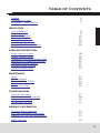
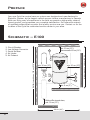
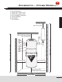
ENGLISH
OWNER’S MANUAL
FOR HOUSEHOLD USE ONLY
Please read this document carefully before installing and/or
using your central vacuum cleaning system.
MODEL : _______________ SERIAL NO : ______________________
IMPORTANT SAFETY INSTRUCTIONS
When using an electrical appliance, basic precautions should always be followed,
including the following.
Read all instructions before using this appliance
WARNING – To reduce the risk of fire, electric shock, or injury:
1. Do not leave appliance when plugged in. Unplug from outlet when not in use
and before servicing.
2. Do not use outdoors or on wet surfaces.
3. Do not allow to be used as a toy. Close attention is necessary when used
by or near children or infirm persons. This appliance is not intended for use
by persons (including children) with reduced physical, sensory or mental
capabilities, or lack of experience and knowledge, unless they have been
given supervision or instruction concerning the use of the appliance by a
person responsible for their safety.
4. Use only as described in this manual. Use only manufacturer’s
recommended attachments.
5. Do not use with damaged cord or plug. If appliance is not working as it
should, has been dropped, damaged, left outdoors, or dropped into water,
return it to a service center.
6. Do not pull or carry by cord, use cord as a handle, close a door on cord, or
pull cord around sharp edges or corners. Do not run appliance over cord.
Keep cord away from heated surfaces.
7. Do not unplug by pulling on cord. To unplug, grasp the plug, not the cord.
8. Do not handle plug or appliance with wet hands.
9. Do not put any objects into openings. Do not use with any opening blocked;
keep free of dust, lint, hair, and anything that may reduce air flow.
10. Keep hair, loose clothing, fingers, and all parts of body away from openings
and moving parts.
11. Do not pick up anything that is burning or smoking, such as cigarettes,
matches, or hot ashes.
12. Do not use without dust bag and/or filters in place.
13. Turn off all controls before unplugging.
14. Use extra care when cleaning on stairs.
15. Do not use to pick up flammable or combustible liquids such as gasoline or
use in areas where they may be present.
16. Connect to a properly grounded outlet only. See Grounding Instructions.
SAVE THESE INSTRUCTIONS
3
Table of Contents
Preface
Schematic – E 100
Schematic – Other Models
6
6
7
INSTALLATION
Unit Installation
Dos & Don’ts
Muffler Installation
Electric Connections
Grounding Instructions
Low Voltage Connections
Installing the Remote Monitor
8
9
12
13
14
15
16
OPERATING INSTRUCTIONS
Hose Hook-up & Inlets
Speed Variation Hose
Progressive Start and Delayed Stop
Maintenance Suggestions Module
Integrated System Monitor
Remote System Monitor
Cyclo Vac Attachments
18
19
19
20
21
21
22
MAINTENANCE
Motor
Dirt Receptacle
Disposable Bag & Filter
Filters
Carbon Dust Filter
24
24
24
25
26
TROUBLESHOOTING
General Information
Decrease in suction strength
Vacuum will not start
Vacuum will not stop
27
28
30
31
WARRANTY INFORMATION
Limited Lifetime Warranty
One Year Satisfaction Guarantee
Warranty on Cyclo Vac Attachments
32
32
33
WEEE Directive
34
5
Preface
Your new Cyclo Vac central vacuum system was designed and manufactured in
Blainville, Quebec, by the largest central vacuum cleaner manufacturer in Canada.
With over forty years of experience in the field, we provide a high-quality, state-ofthe-art product, and guarantee your complete satisfaction. Our extensive network
of qualified professionals ensures first quality service near you. Contact us for the
location of the Cyclo Vac authorized service center in your area.
Schematic – E100
4
min. 30 cm (12")
Recommende 40 cm (16")
min. 30 cm (12")
min. 30 cm (12")
1
2
5
3
min. 5 cm (2")
With muffler turned down,
min. 30 cm (12")
90 cm (36")
6
Muffler turned up, 106 cm (42.5")
Circuit Breaker
Low Voltage Connector
Serial Number
Air Intake
Air Exhaust
Muffler turned down, 154 cm (61.5")
1.
2.
3.
4.
5.
Schematic – Other Models
1.
2.
3.
4.
5.
6.
7.
Circuit Breaker
Reset (DL series only)
LEDs (DL series only)
Low Voltage Connector
Serial Number
Air Intake
Air Exhaust
min. 30 cm (12")
With muffler turned down,
min. 30 cm (12")
7
Muffler turned up, 184 cm (73.5")
1
Muffler turned down, 150 cm (60")
2
3
4
5
6
min. 30 cm (12")
min. 30 cm (12")
min. 30 cm (12")
Recommende 40 cm (16")
95 cm (38")
7
Unit Installation
Using the mounting plate provided with
your vacuum cleaner, secure the unit to
the wall (figure 1), at a height allowing
easy access for maintenance of the
filters, dirt receptacle and/or bags (see
pages 6 and 7).
figure 1
The connections to the piping system will
require some basic tools: a mitre box and
small saw or a pipe cutter (figure 2). See
pages 9 and 10 for general instructions
pertaining to the preparation of PVC
pipes. To simplify matters, installation
kits, including necessary fittings, pipes,
glue and wiring, as well as a detailed
instructions booklet, are available from
Cyclo Vac service centers.
figure 2
Contrary to all other connections in the
piping system, do not glue the last fitting
to your unit. Cyclo Vac central vacuums
are equipped with an adjustable air
intake valve (figure 3), which does not
require glue. An air-tight fit is achieved
with the screw-type adjustment on the
fitting itself.
figure 3
8
Installation
Dos & Don’ts
INSTALLING CONDUITS
Installation
9
Dos & Don’ts
10
Installation
Dos & Don’ts
INSTALLING INLETS
When installing your vacuum inlets, we recommend that the principle of electric
polarity be taken into account. Ensure that the wire connected onto contact A on
inlet 1 is the same as that connected to contact A on inlet 2, and so on. Do not
cross, reverse or interchange wires.
A
B
A
B
inlet 1
inlet 2
Installation
11
Muffler Installation
1. Insert the rubber coupling (A) on the air exhaust (D).
2. Using a Phillips (star shape) screwdriver, tighten the clamp collar on the rubber
coupling to ensure adequate sealing.
3. Insert the 90° elbow (B) into the rubber coupling, and tighten the clamp collar.
4. Insert the muffler (C) on the end of the 90° elbow.
E100 MODEL
C
A.
B.
C.
D.
B
Rubber coupling
90° elbow
Muffler
Air Exhaust
A
D
OTHER MODELS
A
C
A
B
D
12
Installation
Electric Connections
There should be an electric outlet within 1 meter (3 feet) of your central vacuum
unit. Once the appliance is installed in a suitable location, connect your central
unit to an electric outlet on an dedicated* grounded circuit. Do not use extension
cords or modify the length of your vacuum cleaner’s power cord.
DEDICATED* GROUNDED CIRCUIT
• North America
120 V / 240 V All models: 15 A
• European continent and other
220 V / 240 V Model DL200SV: 10 A
220 V /240 V All other models: 8 A
Your central vacuum cleaner has a thermal safety device or a circuit breaker to
protect against any over voltage or electrical defect. If that protection should fail,
contact your authorized service center.
*Please reserve a circuit breaker dedicated only to the connections for your
central vacuum.
If you find that installing your vacuum cleaner is too difficult, ask your service
center to install it for you. When in doubt, it is better to have the work done by a
professional and ensure that the unit is properly installed. Any installation that
does not comply with the specified norms could alter or invalidate the warranty.
Installation
13
Grounding Instructions
This appliance must be grounded. If it should malfunction or breakdown,
grounding provides a path of least resistance for electric current to reduce the
risk of electric shock. This appliance is equipped with a cord having an equipmentgrounding conductor and grounding plug. The plug must be inserted into an
appropriate outlet that is properly installed and grounded in accordance with all
local codes and ordinances. No adaptor should be used with this appliance.
WARNING
Improper connection of the equipment-grounding conductor can result in a risk
of electric shock. Check with a qualified electrician or service person if you are
in doubt as to whether the outlet is properly grounded. Do not modify the plug
provided with the appliance – if it will not fit the outlet; have a proper outlet installed
by a qualified electrician.
120 V MODELS
This appliance is for use on a nominal 120 V circuit,
and has a grounded plug (figure 4). Make sure that the
appliance is connected to an outlet having the same
configuration as the plug. No adaptor should be used with
this appliance.
figure 4
220 V/240 V MODELS
This appliance is for use on a circuit having a nominal rating more than 120 V and
is factory-equipped with a specific cord and plug to permit connection to a proper
electric circuit. Make sure that the appliance is connected to an outlet having the
same configuration as the plug. No adaptor should be used with this appliance. If
the appliance must be reconnected for use on a different type of electric circuit, the
reconnections should be made by a qualified service personnel.
Type C
14
Type G
Type H
Installation
Type I
Nema 6-15 R
Low Voltage Connections
Connect the low voltage wires to the low
voltage inlet on your unit. To do so, simply
strip wires over ½ cm (¼"), remove the
terminals from the low voltage inlet on the
unit, and proceed according to the types of
inlet and wire used.
STANDARD LOW VOLTAGE INLET
figure 5
All types of wire:
Twist the stranded wire to tighten the loose
strands together before proceeding. Insert
the wire into the terminal (blue connector).
Using your wire strippers, tighten the
terminal at two places: at the front, to hold
the wire in place, and at the back to tighten
the insulator around the wire (figure 5). If
the insulator does not completely cover the
stripped wire, use electrical tape to insulate
the wire adquately, and prevent all contact
between the 2 wires. Insert the terminal
into the low voltage inlet (figure 6).
figure 6
To disconnect:
Do not pull on wire. Simply remove the
terminal from the low voltage inlet.
Installation
15
Installing the Remote Monitor
(Optional — DL300 only)
Having determined the location of
both the central vacuum unit and
the Remote System Monitor, run low
voltage wiring to connect the Monitor
to the central vacuum power unit.
Installing the Remote Monitor
1. Insert the low voltage wire into the
mounting box through one of the
designated openings, and fasten
within the wall at the determined
location (figure 11).
figure 11
2. Having stripped the exterior casing
of the four-stranded wire, strip 0,5
cm (¼") of each color wire.
3. Connect wires to the module
connector. Insert each of the 4
color wires in the corresponding
color-coded inlet on the connector.
To do so, loosen the screw on the
side of each inlet, insert the wire,
and tighten screw to ensure a tight
connection. Repeat for each of the
remaining 3 wires (figure 12).
4. Insert the connector to the
electronic module and ensure it
holds in place (figure 13).
A. Red
B. Black
C. Green
D. Yellow
figure 12
figure 13
5. Screw the electronic module to the
mounting box, with the two screws
provided (figure 14).
6. Complete with the “Decora”
finishing plate.
figure 14
16
Installation
Installing the Remote Monitor
(Optional — DL300 only)
Connections on the Vacuum Power Unit
1. Having stripped the exterior casing
of the four-stranded wire, strip 0,5
cm (¼") of each color wire.
2. Connect wires to the power
unit connector. Insert each wire
in the designated inlet, of the
corresponding color. To do so, simply
open the connector, insert the wire,
and close (figure 15). Repeat for the
remaining 3 wires.
figure 15
A. Red
B. Black
C. Green
D. Yellow
Installation
17
Hose Hook-up & Inlets
Before operating your central vacuum…
Please verify that it is properly connected to the piping system, and to a grounded
electrical outlet, and that the low voltage wires are connected to the unit (see
pages 8 to 16). Then read the complete owner’s manual and proceed with a quick
verification of your unit’s installation:
• Check filters to be sure they are properly installed.
• Check rubber seals in each vacuum inlet.
• Plug the hose alternatively into each vacuum inlet, to ensure that each one
works properly.
• While the hose is still plugged into one inlet and the system is operational,
check other inlets for leaks.
To start your central vacuum, simply insert the hose in the vacuum inlet of your
choice. Please ensure that the tab on the hose end is properly lined up with the
slot in the inlet opening (figure 16). If your hose handle has an integrated on/off
switch, simply slide the switch to the “on” position.
Do not try to open another inlet while your system is in operation, as it may
damage the inlet’s rubber seal.
figure 16
18
Operating Instructions
Speed Variation Hose
(DL Series Only)
Exclusive to Cyclo Vac, the Speed Variation hose allows the selection of 4 power
levels by the simple slide of a switch on the hose handle. The light emitting
diodes on the “Speed Variation” hose indicate the power level chosen. Flashing
diodes inform you that the time has come to empty the receptacle or clean the
filters. Refer to the maintenance suggestions module or the integrated system
monitor on the unit itself (see pages 23 and 24).
WARNING
The use of an “SV” hose with a vacuum unit
other than that of the Cyclo Vac DL “SV” series
will cause irreversible damage to your hose which
would not be covered by the warranty.
Progressive Start and Delayed Stop
(DL Series Only)
Each DL model is equipped with a special module allowing for a smooth and
gradual start-up of the vacuum system, to prolong motor durability. It will also
come to a complete stop within a few seconds after it has been turned off, to
allow for the complete evacuation of dust from the hose.
Operating Instructions
19
Maintenance Suggestions Module
(DL Series Only)
RES
)2#5)4"
+
2%! %2
ES S
0R TO
Your unit is equipped with an electronic
timing board that will suggest, by the
color of the blinking LED, the type of
maintenance that should be done. These
signals are only suggestions and do
not indicate a problem with your unit.
Your central vacuum will work normally
despite the flashing LEDs. When you
initially connect your unit, the LEDs will
be green and steady. When the LEDs
on the hose handle blink, no matter the
color, refer to the unit itself for status. It
may be time to change the filters, empty
the dirt receptacle and/or have the
motor(s) inspected.
ET #
Cyclo Alert
Reset
LED
Low
voltage
Blinking green
• We suggest you clean the filters and empty the dirt receptacle.
Blinking amber
• We suggest that you change the filters.
Blinking red
• We strongly suggest you change the filters (if it was not done previsously)
and have an authorized service center inspect the motor(s). A tune-up
may be required.
Blinking green / amber / red
• It is time to bring your unit to an authorized service center. Your unit
has accumulated a considerable number of hours, and may require
maintenance. A complete inspection is therefore strongly recommended.
To reset the electronic timing board
• Hold the reset switch for 10 seconds.
20
Operating Instructions
Integrated System Monitor
(DL300 only)
Your central vacuum unit is equipped with an electronic timing device which
will recommend by a series of light emitting diodes (LEDs) proper maintenance
of your vacuum system. These signals are only suggestions and will do not
indicate a problem with your vacuum system. They will not stop or hinder the
use of the vacuum.
When you initially plug in your vacuum, the LEDs will signal “OK”. Then,
according to the number of hours the system has been use the LEDs will
suggest the proper preventive maintenance.
OK, system is operational
Empty receptacle and clean filters
Change the carbon dust filter
Have the vacuum power unit inspected by an
authorized service center
RESET – press to stop flashing diodes and reset the
electronic timing device.
Remote System Monitor
(Optional — DL300 only)
Installed in a strategic location in your
home, it provides the same information
as the Integrated System Monitor. Once
you have reset the electronic timing device
(on the unit itself), the remote monitor will
once again signal “OK”.
Operating Instructions
21
Cyclo Vac Attachments
Oval Dusting Brush
Use just about anywhere: on lamps & lamp
shades, blinds, shelves, decorative trims
Upholstery Brush
With removable bristles, use to clean all
upholstered furniture such as sofas, chairs,
and mattresses.
Crevice Tool
Use in narrow spaces, nooks and crannies,
such as heating ducts, between sofa
cushions, and between window panes.
Floor Brush
For use on all types of flooring: hardwood,
ceramic or even small carpets.
Carpet Brush (optional)
Specially designed for small carpets and
area rugs, it cleans down deep.
22
Operating Instructions
Cyclo Vac Attachments
Hose Holder
In addition to conveniently holding
your hose, it’s specially designed to
allow the storage of your floor brush
on the telescopic wand, without
crushing the brush bristles.
Telescopic Wand
It’s easily adjusted to the desired
height. Simply depress the button,
slide the wand to the desired length,
and release the button for it to lock
into position. Convenient button-lock
mechanisms prevent the wand from
slipping off the hose handle.
push button here
Attachment Holder
Made of durable vinyl, it conveniently
holds all your accessories. Hang
it on your hose holder, to keep all
accessories at hand.
Operating Instructions
23
Motor
Please note that Cyclo Vac motors do not require lubrication. Each motor
contains two carbon brushes which will wear normally, and may eventually require
replacement. For warranty purposes, this should be done by an authorized service
center. Brush life is affected by the number of hours used, frequency of start-ups
and shut-downs, humidity, altitude, and temperature. In order to avoid damage
to the motor itself, brushes should be replaced before they are completely worn
out. We therefore recommend that you have your unit and motors inspected by a
service center every 5-6 years.
Dirt Receptacle (Except E100 Model)
Occasional maintenance of the dirt receptacle is necessary to ensure constant,
lasting performance. We recommend that it be emptied at least every season,
depending on frequency of use. To empty the dust receptacle, first disconnect your
vacuum cleaner from its power source. Then release the two clamps, lower and
empty the recipient, then replace it and seal by refastening the metal clamps.
Disposable Bag & Filter (E100 Model Only)
Type 3 Bag
Part Number: TDSAC43C
Change the bag when the one in place
is full. Frequency will depend on the use
of the unit.
Line-up the notches in the bag collar
with the tabs on adaptor (figure 17).
Insert the bag as far as the retention
ring, to ensure airtightness.
retention
ring
The disc-shaped filter (figure 18),
located between the dust bag and the
motor, should be changed once for
every three bags (45 hours of use), or
more often as needed.
figure 17
Use only genuine Cyclo Vac replacement
bags. Failure to do so could void the
warranty on your vacuum unit.
figure 18
24
Maintenance
Filters
(Except E100 Model)
We recommend regular maintenance of the
filtration system, in order to ensure your
central vacuum’s maximum performance.
Your Cyclo Vac central vacuum is equipped
with two filters. An anti-clogging filter
(thin fabric) stops the larger particles,
and a Cyclofiltre (thick fabric) catches
the microscopic particles and is treated
with Ultra-Fresh* to prevent the growth of
mold, fungus and bacteria. Both filters are
washable in cold water (no bleach). Dry at
low temperature.
figure 19
To remove the filters, first remove the dust
receptacle (figure 19), then use the straps
at the base of the filters to withdraw them
(figure 20). We recommend that you clean
the anti-clogging filter (thin fabric) every
time you empty the dust receptacle. You
may either shake it out, or wash it. The
Cyclofiltre (thick fabric) should be cleaned
after four anticlogging filter cleanings, or
approximately once a year.
It is important that both filters be
completely dry before they are reinstalled.
They should be carefully installed in the
support grooves (figure 21) on the filter
frame to ensure adequate protection for
the motor. Install the Cyclofiltre (thick
fabric) first, and the anticlogging filter (thin
fabric) over it.
figure 20
Before replacing the filters, inspect them
for tears or punctures. Do not reinstall
damaged filters.
figure 21
*Ultra-Fresh is a trademark of Thomson Research Associates.
Maintenance
25
Carbon Dust Filter (Patent pending)
(E300 and DL300 Only)
We recommend that you change this filter
once for every three maintenances of the dirt
receptacle (see page 26). For the DL300,
the integrated monitor will indicate when
to change this filter. These indications are
provided by an electronic timing board, only as
a reference guide.
To do so:
1. Unlatch the opening on the carbon filter
case and gently flip it upward (figure 22).
figure 22
2. Remove the used filter, and discard
(figure 23).
3. Insert the new filter. When doing so, please
ensure that the arrow printed on the filter
itself points outwards (figure 24).
4. Close casing opening, and latch.
figure 23
figure 24
26
Maintenance
General Information
If the vacuum unit does not work, check the fuse or breaker on the unit and/
or in the electrical panel in your home, and replace any defective part(s) as
deemed necessary. Please verify that the unit has been installed properly,
according to the instructions in this manual.
Your vacuum cleaning system is designed to collect everyday dry matter
(dust). It is approved by authorized testing agencies for dry use only. Do not
use on wet surfaces.
Should you accidentally vacuum liquids, immediately unplug the unit from the
electric outlet, then empty and wipe the dust recipient with a dry cloth. Then
operate the system from the vacuum inlet through which you vacuumed the
liquid, in order to eliminate all moisture in the piping system.
We strongly recommend against vacuuming abrasive materials such as
cement, plaster and gyproc dust. This fine dust could work its way into
the motor, causing considerable damage. Should you do so inadvertently,
immediately clean the filters and, as a precautionary measure, contact your
authorized service center to determine the extent of the damage to the unit.
Remember that in order for your warranty to remain valid, maintenance of
the motor and repairs to the unit itself must be carried out by an authorized
service center, using original Cyclo Vac or Trovac parts.
Troubleshooting
27
Troubleshooting
28
PROBLEM
POSSIBLE CAUSE
CORRECTIVE ACTION
Decrease in suction
strength
Dirt recipient / Bag is full Empty dirt recipient /
change bag (see page
25).
Dirt recipient is not
properly attached
Check clamps holding
dirt recipient, to make
sure they are tight, and
dirt recipient is aligned.
Filters need cleaning /
replacing
Remove, shake and/or
wash filters or replace
them (depending on
model) before reinstalling
them in the unit (see
page 26).
Motor guard screen is
blocked
Remove filters, and
check the guard screen
(which separates the
motor from the filtration
compartment) for
blockage. Ensure filters
are always properly
installed, to prevent this
problem from happening
again.
Open vacuum inlet
Close all vacuum inlets
not in use.
Exhaust line is clogged
Verify that no object is
blocking the exhaust.
Troubleshooting
Troubleshooting
PROBLEM
POSSIBLE CAUSE
CORRECTIVE ACTION
Decrease in suction
strength (cont.)
Blocked hose
Plug the handle end of
the hose into the suction
inlet, thus reversing the
suction in the hose.
Cover the gap around
the handle, to ensure
suitable suction strength,
and ensure contact with
inlet contacts to start the
unit. This should clear
the hose.
Obstruction in the piping
system
Remove the screw from
the air intake connector,
to free the central
vacuum unit from the
piping system (see figure
3 on page 8). Start the
unit by plugging the
hose into a vacuum
inlet. By placing your
extended hand over the
air intake opening on the
unit, check the suction
strength on the unit itself.
If suction strength is
normal, the obstruction
is in the piping system.
If suction strength is
diminished or completely
absent, have the unit
checked by an authorized
service center.
If none of these suggestions restore suction strength, contact
your authorized service center.
Troubleshooting
29
Troubleshooting
30
PROBLEM
POSSIBLE CAUSE
CORRECTIVE ACTION
Vacuum will not start
The electrical power is
not connected properly
Ensure that the
power cord is plugged
into a dedicated
grounded electrical
outlet, according to
specifications on pages
13 and 14.
Low voltage wire not
connected properly
Verify the low voltage
wires, make sure they are
properly inserted into the
low voltage inlet, as per
instructions on page 15.
Faulty vacuum inlet
Start the vacuum unit
from other inlets in your
home, to identify the
defective inlet.
Unit circuit breaker is off
Press the reset button
to reset the unit circuit
breaker. If unit restarts
and automatically shuts
off shortly after, contact
an authorized service
center.
In-house circuit breaker
is off
Reset the circuit breaker
in your electrical panel.
Verify that your central
vacuum unit is connected
on a dedicated grounded
circuit (see pages 13
and 14).
Defective on/off hose
Turn the hose ¼ turn in
the vacuum inlet. If unit
starts, have the vacuum
hose checked by a
certified service center.
Troubleshooting
Troubleshooting
PROBLEM
POSSIBLE CAUSE
CORRECTIVE ACTION
Vacuum will not stop
Hose improperly inserted Ensure that the hose
into vacuum inlet
end is properly placed
in the vacuum inlet: the
tab on the hose should
fit into the slots on the
inlet, to ensure adequate
contacts for the hose
switch to function (see
page 18).
Defective on/off hose
If the hose is properly
placed in the vacuum
inlet, and the unit
continues running
despite the fact that
the hose switch is in
the “off” position, have
the hose checked by a
service center.
Low voltage wire not
connected properly
While vacuum is on,
unplug low voltage
wires from unit. If
vacuum stops, there’s a
faulty low voltage wire.
Contact your installer
or authorized service
center.
Troubleshooting
31
Warranty Information
LIMITED LIFETIME WARRANTY
Your Cyclo Vac vacuum system is protected by a lifetime warranty. We guarantee
that the unit canister will be exempt of any material or manufacturing defect.
This warranty is valid from the date of purchase, for as long as you are the
original owner, and the system remains at its original place of installation.
The motors and electrical components of both E and DL series are entirely
guaranteed for a period of 5 years. As for our DL series, in addition to the
5 year warranty, the motors and electrical components are guaranteed at 50 %
for an additional 5 year period. Our authorized service center will repair or
replace (at Cyclo Vac’s discretion) the defective part or parts, free of labor costs,
for a period of 5 years. For the DL series, labor costs are covered at 50 % for an
additionnal 5 years.
Cyclo Vac Warranty
Motors and Electrical Components
MODEL
YEAR
PARTS
LABOR
E Series
1 to 5
100 %
100 %
DL Series
1 to 5
6 to 10
100 %
50 %
100 %
50 %
In order to maintain your warranty, all repairs must be made by an authorized
Cyclo Vac service center, with original Cyclo Vac or Trovac parts. Failure to do so
could void the warranty.
This warranty excludes normal wear and tear of certain parts such as filters,
damages caused (according to Cyclo Vac) by abusive use (ex.: drywall dust,
water, etc.), commercial use, the lack of appropriate maintenance, inadequate
installation, negligence, natural disasters, accidents, and acts of God.
ONE YEAR SATISFACTION GUARANTEE
We are certain you’ll be completely satisfied with your Cyclo Vac central vacuum
system. For one year following the date of purchase, if the vacuum unit does
not meet your expectations, return it to your local Cyclo Vac service center for a
complete refund or credit towards the purchase of another Cyclo Vac model. This
warranty applies only to the vacuum power unit.
32
Warranty Information
Warranty Information
THREE YEAR WARRANTY ON CYCLO VAC RECOMMENDED* ATTACHMENTS
All Cyclo Vac recommended attachments* are guaranteed for three years, subject
to certain conditions. If during this three year period, an accessory presents a
manufacturing defect, return it to the nearest authorized Cyclo Vac service center
along with a copy of your invoice (clearly indicating the attachments purchased),
and we will repair or replace the part according to the conditions of the warranty.
This warranty does not cover normal wear and tear of components such as: belts,
brushes, rollers and their components, nor abusive use. It is valid only for normal
domestic use.
*Your Cyclo Vac recommended attachments are clearly identified by a Cyclo Vac
logo. Any other attachment, even if purchased at a Cyclo Vac sales center at the
same time as your power unit, is not covered by the 3 year Cyclo Vac warranty.
This warranty is valid for domestic use only. This warranty is not a modification
but an addition to warranties required by law. Any claim relative to this warranty
must be accompanied by the original invoice. Any changes or modifications made
to the product may invalidate this warranty. Transportation and service calls are
excluded . This warranty is non transferable.
Keep all payment records (bill of sale, delivery slip). The date on these records
establishes the warranty period. Should warranty service be required, you must
show proof of purchase. If proof of purchase cannot be supplied, the warranty
period will be determined from the date of manufacture of the product.
Cyclo Vac shall not be held responsible for any consequential, incidental, or
special damages arising from the use of this central vacuum.
Warranty Information
33
WEEE Directive
Important Environmental Information – European Economic Area only
This appliance has been assessed in accordance with the European Parliament
Directive on Waste Electrical and Electronic Equipment, usually referred to as the
WEEE Directive.
The WEEE Directive requires that the appliance be disposed of at the end of its
useful life in an environmentally responsible manner. Parts and materials should
be re-used or re-cycled in order that the use of new resources and amount of
waste going for landfill can be minimised.
The WEEE Directive stipulates that the supplier should collect the used item
without cost to you. Please inform the supplier of your wish to have the old
appliance collected when ordering the replacement.
If you wish to dispose of the appliance yourself, do not mix it with unsorted
municipal waste. The crossed-out wheeled bin symbol on the unit label (figure 25)
indicates this requirement. You must ensure that the appliance is disposed of at
an authorised treatment facility. Details can be obtained from your local council.
figure 25
34
Warranty Information
WWW.CYCLOVAC.COM
Head Office / Siège social / Oficina Central
[email protected]
1 888 77CYCLO
Distribution Centers / Centres de distribution / Centros de distribución
CANADA
CANADA
1260, Lakeshore Road
Missisuaga, ON L5E 3B8
19578, 55A Avenue
Surrey, BC V3S 8P8
1 800 665-2500
(604) 514-7005
1 800 665-2500
USA
USA
3873 Airport Way
Bellingham WA 98226
5460, Florin Perkins Road
Sacramento CA 95826
1 800 665-2500
1 800 325-3434
1 916 361-7491
EUROPE
16, rue du Stade
44170 Treffieux
Tel. : + 33 (0) 2 40 51 44 60 • Fax : + 33 (0) 2 40 51 42 24
[email protected]
Nº vert: 0800 800 393
PRINTED IN CANADA • IMPRIMÉ AU CANADA • IMPRESO EN CANADÁ
Tel. : (450) 434-2233 • Fax : (450) 434-6111
IMPMOD20 - AU’07
CANADA
3, rue Marcel-Ayotte
Blainville (Québec) J7C 5L7