1
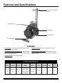
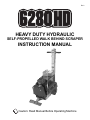
Rev A
HEAVY DUTY HYDRAULIC
SELF-PROPELLED WALK BEHIND SCRAPER
INSTRUCTION MANUAL
Caution: Read Manual Before Operating Machine
Table of Contents
Table of Contents ................................................................................................................................................................................................... 3
Features and Specificatons ................................................................................................................................................................................... 4
Safety .................................................................................................................................................................................................................... 5-8
General Rules for Safe Operation ................................................................................................................................................................ 5
Characteristics of a Defensive Operator ....................................................................................................................................................... 6
Hydraulic Safety Tips .................................................................................................................................................................................... 6
Grounding ..................................................................................................................................................................................................... 7
Extension Cords ........................................................................................................................................................................................ 7-8
Machine Operation ............................................................................................................................................................................................ 9-14
Transporting.................................................................................................................................................................................................. 9
Wheels Engaging or Disengaging ................................................................................................................................................................ 9
Loading/Unloading ................................................................................................................................................................................... 9-10
Operating Controls...................................................................................................................................................................................... 10
Angle Attachments .......................................................................................................................................................................................11
Mounting Angle Attachments .......................................................................................................................................................................11
Preparing Machine For Job ........................................................................................................................................................................ 12
Blade Changing .......................................................................................................................................................................................... 12
Blade Sharpening ....................................................................................................................................................................................... 13
Types of Tearouts .................................................................................................................................................................................. 13-14
Blades ............................................................................................................................................................................................................... 15-16
Machine Maintenance ..................................................................................................................................................................................... 17-18
Wheel Cleaner Adjustment ......................................................................................................................................................................... 17
Wheel Removal .......................................................................................................................................................................................... 17
Adding or Changing Hydraulic Fluid ........................................................................................................................................................... 17
Inspection of Internal Parts ......................................................................................................................................................................... 17
Tank Removal ............................................................................................................................................................................................. 18
Forward and Reverse Switch Replacement ............................................................................................................................................... 18
Power Cord ................................................................................................................................................................................................. 18
On/Off Switch Wire Diagram....................................................................................................................................................................... 18
Cartridge Replacement ............................................................................................................................................................................... 18
Troubleshooting Guide ........................................................................................................................................................................................ 19
Complete Parts List ......................................................................................................................................................................................... 20-21
Parts List and Diagrams ................................................................................................................................................................................. 22-36
External Parts ............................................................................................................................................................................................. 22
Base Plate Parts ......................................................................................................................................................................................... 23
Idler Assembly Parts ................................................................................................................................................................................... 24
Pump Drive Assembly Parts ....................................................................................................................................................................... 24
Eccentric Assembly Parts ........................................................................................................................................................................... 24
Body Parts .................................................................................................................................................................................................. 25
Bottom Cover Parts .................................................................................................................................................................................... 25
Axle Assembly Parts ................................................................................................................................................................................... 26
Wheel Parts ................................................................................................................................................................................................ 26
Internal Handle Parts .................................................................................................................................................................................. 27
Handle Parts ............................................................................................................................................................................................... 27
Hose Parts .................................................................................................................................................................................................. 28
Tank Parts ................................................................................................................................................................................................... 28
Motor Parts ................................................................................................................................................................................................. 29
Cutting Head Parts ..................................................................................................................................................................................... 30
Switch Parts ................................................................................................................................................................................................ 30
Head Securing Parts................................................................................................................................................................................... 30
Internal Parts .............................................................................................................................................................................................. 31
Labels .................................................................................................................................................................................................... 32-33
Accessories ................................................................................................................................................................................................ 34
6280HD Wiring Diagram ............................................................................................................................................................................. 35
6280HD Hydraulic Line Layout ................................................................................................................................................................... 36
Material Safety Data Sheet (MSDS) Information ........................................................................................................................................... 37-40
Guarantee .............................................................................................................................................................................................................. 41
www.nationalequipment.com
3
Phone: 763-315-5300
Features and Specifications
Quick Adjust Multi Position
Handle
Lifting Ball Eyebolts
Slide Weights
Traction Wheels
Unique Swivel Head
FEATURES
Traction Wheels - These industrial grade wheels are self-cleaning
and disengage for loading/unloading.
Unique Swivel Head - Unique swivel head provides continuous
contact with the floor.
Side Slide Weights with Quick Adjust Levers - Applies additional
pressure to the scraper head as desired or if more traction is needed,
slide them back over the wheels.
Quick Adjust Multi Position Handle - Allow adjustment of handle
angle to suit operator or work conditions. Folds flat over machine for
storage or transport.
Lifting Bail Eyebolts - Eases loading/unloading.
Product Specifications
Width
Length
Height
40.6 cm
83.8 cm
119.4 cm
(16”)
(33”)
(47”)
Fax: 763-535-8255
Weight
165.6 kg (365 lb)
(machine only)
222.3 kg (490 lb)
(with weights)
Speed
9.1 m/min
(30 ft/min)
4
RPM
Voltage
HP
1725/1425
115
1.5
Amps
(full load)
13
[email protected]
Safety
GENERAL RULES FOR SAFE OPERATION
READ AND SAVE ALL INSTRUCTIONS FOR FUTURE USE. Before use, ensure operators reads and understand this manual. Read and
understand labeling on machine and components. All operators must view the instruction video. Extra copies of the manual and video are available by contacting National Flooring Equipment.
1.
KNOW YOUR EQUIPMENT: Read this manual carefully to learn equipment applications and limitations, potential hazards associated with
this type of equipment. Keep this manual with the equipment it is associated with.
2.
GROUND YOUR EQUIPMENT: See Grounding Page 7.
3.
AVOID DANGEROUS ENVIRONMENTS: Do not use in rain, damp or wet locations or in the presence of explosive atmospheres (gaseous
fumes, dust or flammable materials). Remove materials or debris that may be ignited by sparks.
4.
KEEP WORK AREA CLEAN AND WELL LIT: Cluttered, dark work areas invite accidents.
5.
DO NOT USE ON STEPS.
6.
DRESS PROPERLY: Do not wear loose clothing. These may be caught in moving parts. When working wear gloves and insulated non-skid
footwear. Keep hands and gloves away from moving parts.
7.
USE SAFETY EQUIPMENT: Proper eye protection should be worn at all times. Wear hearing protection during extended use and a dust
mask for dusty operations. Hard hats, face shields, safety shoes, etc. should be worn when specified or necessary.
8.
KEEP BYSTANDERS AWAY: Children and other bystanders should be kept at a safe distance from the work area to avoid distracting the
operator and contacting the equipment or extension cord. Operator should be aware of the proximity of bystanders. This appliance is not
intended for use by persons (including children) with reduced physical, sensory or mental capabilities or lack of experience and knowledge.
Equipment is not to be used by children.
9.
PROTECT OTHERS IN THE WORK AREA: Provide barriers or shields as needed to protect others from debris.
10. USE PROPER ACCESSORIES: Using accessories that are not recommended is hazardous. Be sure accessories are properly installed
and maintained. Do not remove a guard or other safety device when installing an accessory or attachment.
11. CHECK FOR DAMAGED PARTS: Inspect guards and other parts before use. Check for misalignment, binding of moving parts, improper
mounting, broken parts and other conditions that may affect operation. If abnormal noise or vibration occurs, turn off immediately and have
the problem corrected before further use. Do not use damaged equipment. Tag damaged equipment “DO NOT USE” until repaired. Missing or damaged parts should be properly repaired or replaced immediately. For all repairs, use only identical National replacement parts.
12. REMOVE ALL ADJUSTING KEYS AND WRENCHES: Make a habit of checking that the adjusting keys, wrenches, etc. are removed from
the tool before turning it on.
13. GUARD AGAINST ELECTRIC SHOCK: Prevent body contact with grounded surfaces such as pipes, radiators, ranges and refrigerators.
When making cuts, always check the work area for hidden wires or pipes. Hold your equipment by insulated nonmetal grasping surfaces.
Use a Ground Fault Circuit Interrupter (GFCI) to reduce shock hazards.
14. AVOID ACCIDENTAL STARTING: Be sure equipment is turned off before plugging in. Do not use equipment if the power switch does not
turn the equipment on and off.
15. DO NOT FORCE EQUIPMENT: Equipment will perform best at the rate for which it was designed. Excessive force only causes operator
fatigue, increased wear and reduced control.
16. KEEP HANDS AWAY FROM ALL CUTTING EDGES AND MOVING PARTS.
17. WEAR gloves when changing accessories.
18. DO NOT ABUSE CORD: Never unplug by pulling the cord from the outlet. Pull plug rather than cord to reduce the risk of damage. Keep
the cord away from heat, oil, sharp objects, cutting edges and moving parts.
19. DO NOT OVERREACH. MAINTAIN CONTROL: Keep proper footing and balance at all times. Maintain a firm grip.
20. STAY ALERT: Watch what you are doing, and use common sense. Do not use when you are tired, distracted or under the influence of
drugs, alcohol or any medication causing decreased control.
21. STARTING MACHINE: On/Off switch must be in off position before connecting to power source.
22. UNPLUG EQUIPMENT: When not in use and before changing accessories or performing recommended maintenance, unplug machine.
23. MAINTAIN EQUIPMENT CAREFULLY: Keep handles dry, clean and free from oil and grease. Keep cutting edges sharp and clean. Follow
instructions for lubricating and changing accessories. Inspect tool cords and extension cords for damage. Replace damaged parts. Use
www.nationalequipment.com
5
Phone: 763-315-5300
Safety
only identical National replacement parts.
24. STORE IDLE EQUIPMENT: When not in use, store in a dry, secured place. Keep away from children.
25. MAINTAIN LABELS AND NAMEPLATES: These carry important information. If unreadable or missing, contact National for a replacement.
26. MACHINE IS HEAVY, DO NOT DROP. Ensure proper lifting procedures are followed when transporting.
27. DO NOT ALLOW the oscilating plates to come into contact with the supply cord.
28. REGULARLY EXAMINE the supply cord for damage, such as cracking or aging. If damaged, replace the cord before further use. Only
replace the supply cord with the type specified in this manual.
CHARACTERISTICS OF A DEFENSIVE OPERATOR
A Good Operator is a “Defensive” Operator!
QUALITIES INCLUDE:
Education: Educates themself on the machine and the environment.
Alert: Stays alert at all times and never lets guard down.
Skills: Only performs duties he/she is qualified to do. Always tries to improve.
Judgment: Uses sound judgement. Does not take uncessary risks.
Common Sense: Applies knowledge in practical situations.
Recognizes the Hazards: Maintains alertness. Anticipates danger.
Understands the Defense: Knows that safety isn’t an accident…it’s a thinking person’s choice.
Acts Correctly: Does not give in to peer pressure. Performs correctly when supervised or not.
HYDRAULIC SAFETY TIPS
MAINTAINING A SAFE WORK ENVIRONMENT
Establishing a safe working environment in and around your hydraulic equipment is just common sense. The easiest and most effective way to
avoid problems is to make sure associates understand their equipment, know how to operate it safely and recognize the danger it represents if
handled carelessly. A few things you must be aware of include:
1. PRESSURE: Hydraulic fluid under pressure is dangerous and can cause serious injury.
2. FLAMMABILITY: When ignited, some hydraulic fluids can explode and/or cause fires.
3. MECHANICAL: Hydraulic fluid creates movement, which causes parts of your equipment to move or rotate. Always be aware of what
you are doing.
4. MOISTURE: Use caution when operating in wet or high moisture conditions. Make sure all electrical fittings, switches, cords plus stain
reliefs are in good condition. Always unplug when not in use and when doing any service work.
5. ELECTRICAL: Faulty wiring can also be an electrical hazard. A regular preventive maintenance program should always include a wiring check. Unplug batteries and/or charger before serving.
6. TEMPERATURE: Because this machine operates at a relatively low pressure, overheating is not common. If surface of tank becomes
too hot to touch by hand (above 130º F, 55° C), shut off machine and allow to cool off.
PRESSURE
Our system runs at or below 2,000 psi. Never look for a leak when unit is under pressure. Using your hand could cause serious injury. A few
common ways to encounter hydraulic fluid under pressure include:
1. PINHOLE: Fluid under pressure can cause serious injury. It can be almost invisible escaping from a pinhole, and it can pierce the skin
into the body. Do not touch a pressurized hydraulic hose assembly with any part of your body. If fluid punctures the skin, even if no pain is
felt, a serious emergency exists. Obtain medical assistance immediately. Failure to do so can result in loss of the injured part or death.
2. LEAK: Keep fittings and hoses tight. Only check and service when not under pressure. Leaking hydraulic fluid is not only unsightly, it’s
hazardous. In addition to making workplace floors slippery and dangerous, leaks also contaminate the environment. Before cleaning an oil
spill, always check EPA, state and local regulations.
Fax: 763-535-8255
6
[email protected]
Safety
CAUTION: NEVER USE YOUR HANDS TO CHECK FOR LEAKS OVER HOSE
OR HYDRAULIC CONNECTIONS. USE A PIECE OF CARDBOARD TO LOCATE
A PRESSURIZED LEAK. FOR LOW PRESSURE LEAKS (DRIPS), USE A RAG TO
CLEAN THE AREA AND DETERMINE WHERE THE LEAK ORIGINATES.
3. BURST: Whether due to improper selection or damage, a ruptured hose can
cause injury. If it bursts, a worker can be burned, cut, injected or may slip and fall.
4. COUPLING-BLOW OFF: If the assembly is not properly made or installed,
the coupling could come off and hit or spray a worker, possibly resulting in serious
injury. Never operate machine without guards.
FIG. A
FLAMMABILITY
With the exception of those comprised primarily of water, all hydraulic fluid is flammable
when exposed to the proper conditions (including many “fire-resistant” hydraulic fluids).
Leaking pressurized hydraulic fluids may develop a mist or fine spray that can flash or
explode upon contact with a cause of ignition. These explosions can be very severe and
could result in serious injury or death.
Precautions should be taken to eliminate all ignition sources from contact with escaping fluids, sprays or mists resulting from hydraulic failures. Sources of ignition could be
electrical discharges (sparks), open flames, extremely high temperatures, sparks caused
by metal-to-metal contact, etc.
HYDRAULIC FLUID
Only use Texaco Rando 46 Hydraulic Oil or Compatible Fluid like IS032. Non-compatible
fluids could cause damage to unit or serious injury.
GROUNDING
Tools marked “Grounding Required” have a three wire cord and three prong grounding
plug. The plug must be connected to a properly grounded outlet (Figure A). If the tool
should electrically malfunction or break down, grounding provides a low resistance path
to carry electricity away from the user, reducing the risk of electric shock.
The grounding prong in the plug is connected through the green wire inside the cord to
the grounding system in the tool. The green wire in the cord must be the only wire connected to the tool’s grounding system and must never be attached to an electrically “live”
terminal.
Your scraper must be plugged into an appropriate outlet, properly installed and grounded
in accordance with all codes and ordinances. The plug and outlet should look like those
in Figure A.
EXTENSION CORDS
Grounded tools require a three wire extension cord. Double insulated tools can use either
a two or three wire extension cord. As the distance from the supply outlet increases,
you must use a heavier gauge extension cord. Using extension cords with inadequately
sized wire causes a serious drop in voltage, resulting in loss of power and possible tool
damage.
WARNING: IMPROPERLY CONNECTING THE GROUNDING WIRE CAN
RESULT IN THE RISK OF ELECTRIC SHOCK. CHECK WITH A QUALIFIED ELECTRICIAN IF YOU ARE IN DOUBT AS TO WHETHER THE OUTLET IS PROPERLY
GROUNDED. DO NOT MODIFY THE PLUG PROVIDED WITH THE TOOL. NEVER
REMOVE THE GROUNDING PRONG FROM THE PLUG. DO NOT USE THE TOOL
IF THE CORD OR PLUG IS DAMAGED. IF THE PLUG WILL NOT FIT THE OUTLET,
HAVE A PROPER OUTLET INSTALLED BY A QUALIFIED ELECTRICIAN.
www.nationalequipment.com
7
Phone: 763-315-5300
Safety
The smaller the gauge number of the wire, the greater the capacity of the cord. For example, a 10 gauge cord can carry a higher current than
a 12 gauge cord. When using more than one extension cord to make up the total length, be sure each cord contains at least the minimum
wire size required. If you are using one extension cord for more than one tool, add the nameplate amperes and use the sum to determine the
required minimum wire size.
GUIDELINES FOR USING EXTENSION CORDS
•
If you are using an extension cord outdoors, make sure it is marked with the suffix “W-A” to indicate that it is acceptable for outdoor use.
•
Be sure your extension cord is properly wired and in good electrical condition. Always replace a damaged extension cord or have it repaired by a qualified person before using it.
•
Protect your extension cords from sharp objects, excessive heat and damp or wet areas.
•
Keep away from water. Do not use if wet.
•
Inspect thoroughly before each use. DO NOT USE IF DAMAGED.
•
Make sure equipment is OFF before connecting cord outlet.
•
FULLY INSERT plug into outlet.
•
Do not remove, bend or modify any metal prongs or pins of cord.
•
Do not use excessive force to make connections.
•
Do not connect a three prong plug to a two-hole cord.
•
Avoid overheating. Uncoil cord and do not cover it with any material.
•
Do not walk on cord.
•
Do not drive, drag or place objects over cord.
•
National recommends using a single 50’ (15 m) 12 gauge extension cord.
WARNING: ELECTRICAL CORDS CAN BE HAZARDOUS. MISUSE CAN RESULT IN FIRE OR DEATH BY ELECTRICAL SHOCK. READ
CAREFULLY AND FOLLOW ALL DIRECTIONS.
Fax: 763-535-8255
8
[email protected]
Machine Operation
TRANSPORTING
WHEELS ENGAGING OR DISENGAGING
Wheels engage and disengage for easier maneuverability. Wheels in the “engage mode”
are secured with the axle pins (See Figure B). This engages the wheels for the machine
to be self-propelled.
When wheels are in the “disengage mode” (See Figure C). Machine can be moved
around freely when the machine IS NOT under power.
DISENGAGING WHEELS
FIG. B
Pull up on end of pin to release. Slide pin out. Repeat on second wheel. Note: Keeping
axle pin facing straight up will make re-engaging easier.
RE-ENGAGING WHEELS
Line up wheel hub hole and axle hole (See Figure E). Insert axle pin and secure pin end.
Repeat on second wheel.
LOADING/UNLOADING
LIFTING BAIL
The lifting bails make loading/unloading easier when not able to drive or using a ramp.
Location on lifting bails centrally locates balance of the machine to safely pick-up machine.
1.
Place rope, hook system or chain through eyelets located on top of machine (See
Figure F).
2.
Raise machine with a fork lift or winch.
3.
Slowly lower to desired location.
CAUTION: ALWAYS REMOVE ALL COUNTER WEIGHTS & BLADES AND
MAKE SURE THE WHEELS ARE IN “ENGAGE MODE” (FIGURE D) BEFORE
LOADING OR UNLOADING. FAILURE TO DO SO COULD RESULT IN PROPERTY DAMAGE AND/OR PERSONAL INJURY.
FIG. C
FIG. D
FIG. E
FIG. F
www.nationalequipment.com
9
Phone: 763-315-5300
Machine Operation
RAMP LOADING
1.
2.
3.
4.
Put the wheels in “engage mode”.
Make sure ramp is clean and dry, free of grease or oil.
Position ramp securely to back of vehicle, making sure there is good contact (See
Figure G).
Position machine at bottom of ramp (See Figure H).
5.
Engage power switch and drive onto vehicle.
RAMP UNLOADING
FIG. G
1.
2.
3.
4.
Put the wheels in “engage mode”.
Position ramp securely to back of vehicle, making sure there is good contact (See
Figure G).
Position machine at the back of the truck in line with the ramp (See Figure H).
Carefully move machine onto ramp leaving cutting head down (in contact with ramp
surface). CAUTION: Machine even without weights weighs 318 pounds (165 kg).
Make sure you have machine under control. Failure to do so could cause machine
runaway, damage to machine, damage to property or cause serious injury.
5.
Slowly back machine down ramp.
OPERATING CONTROLS
FIG. H
MACHINE START-UP PROCEDURE:
1.
2.
3.
4.
5.
Machine MUST be off before plugging machine into power source.
Plug machine into outlet.
Turn speed control to slowest position.
Push “ON/OFF” switch to the ON position.
Engage forward or reverse switch.
6.
Increase speed control to desired speed.
SPEED CONTROL
FIG. I
FASTER
SLOWER
•
Speed control knob can be adjusted while machine is running.
•
Turning speed control knob counter clockwise will increase maximum forward
speed (See Figure J).
•
Turning speed control knob clockwise will decrease maximum forward speed (See
Figure J).
ADDING/REMOVING OPTIONAL SLIDE SIDE WEIGHTS
To move the side slide weight forward/back based on job application conditions,
raise the lever and gently shift the weight to the desired location. After moving each
side slide weight to this position, lower the lever into the channel in the weight.
FIG. J
Fax: 763-535-8255
10
[email protected]
Machine Operation
ANGLE ATTACHMENTS
7280-2B STEEP ANGLE
ATTACHMENT 22°
The angle attachments angles the cutting head and blade or carbide shank to where the
material comes up the easiest. Lower is usually the best.
MOUNTING ANGLE ATTACHMENT
•
Disconnect machine from power source.
•
Tilt machine back.
•
Securely block machine up (See Figure M).
•
Insert desired cutting head or carbide shank into the angle attachment.
22°
FIG. K
NOTE: CUTTING HEAD OR CARBIDE SHANK SHOULD FREELY SWIVEL IN THE ANGLE
ATTACHMENT. THIS MOVEMENT ALLOWS THE BLADE TO STAY IN CONTACT WITH THE
FLOOR. GREASE MAY NEED TO BE APPLIED TO THE SHAFT OF THE ATTACHMENT BEFORE
INSERTING.
•
Secure with Retainer Cap (See Figure N)
•
Mount angle attachment onto the cutting head support (See Figure O).
•
Securely tighten all five mounting bolts.
7280-2C STEEP ANGLE
ATTACHMENT 30°
30°
FIG. L
BLOCK
FIG. M
FIG. N
FIG. O
www.nationalequipment.com
11
Phone: 763-315-5300
Machine Operation
PREPARING MACHINE FOR JOB
BLADE SETTING
Note: The 6280HD is designed for soft goods and most hard good removal applications.
•
Proper blade size and placement, depending on material and sub-floor type, affects performance.
•
The harder a job comes up, for best results, use a smaller blade.
•
Start with a narrow blade, then increase blade size to optimize cutting pass. Narrower blades work easier than wider blades and usually clean the floor better.
Wider is not always better or faster.
•
Normally bevel on blade is up for concrete (Figure P). Bevel down for wood (Figure
Q).
•
KEEP BLADES SHARP. Dull blades greatly affect the performance of the machine
and reduce cutting ability, resharpen or replace as needed.
•
Keep your work area clean and clear of debris. After you have removed a portion
of material, remove it out of the way. This will give the machine maximum performance and help to keep the work area safe.
•
Always wear gloves when handling blades.
•
Everyone in work area should wear eye protection.
•
Wood or wood like floors: pound down or remove any nails or metal obstruction to
avoid blade damage.
•
Blades can be offset in cutting head for easier access to toe kicks or removal along
the wall (See Figure R).
•
Sheet vinyl, solid vinyl, rubber tile, urethane or PVC sheet roofing, will need to be
scored for best removal results. Nationals #584 Scoring Tool (See Figure S). Score
flooring to the width of the blade.
•
Self scoring blades are available in a number of sizes. These blades eliminate the
need for pre-scoring material. Depending upon the type of material being removed
and the sharpness of the blade and scoring wings, the self scoring blades may
make it harder to control the machine. Keep scoring wings sharp at all times.
FIG. P
FIG. Q
FIG. R
BLADE CHANGING
1.
Place a block under the front of the machine as shown in Figure T, using a flat piece
of 2 x 4 or something similar.
2.
Use supplied extended “T” wrench or a 7/32 Allen wrench with at least a 3” extension to keep hand safely away from the sharp edge of the blade. Loosen four (4)
allen head bolts. It is not necessary to remove bolts.
3.
Place blade into cutting head, sliding all the way back to the bolts. If the blade is
wider than the cutting head, center blade to head. If blade is smaller than the cutting head, first pass blade should be mounted in center of the cutting head. After
first pass is made, blade can be offset in head to allow wheels to keep even contact
with the floor and allow easy access to the wall.
4.
Hand tighten the bolts.
FIG. S
CAUTION: BLADES ARE SHARP, USE EXTREME CAUTION WHEN HANDLING. NEVER CHANGE CUTTING HEAD OR SERVICE BLADES WHILE
MACHINE IS RUNNING.
FIG. T
www.nationalequipment.com
12
Phone: 763-315-5300
Machine Operation
BLADE SHARPENING
Dull blades greatly reduce cutting ability. Re-sharpen or replace as needed. In use,
blades develop a back-bevel (Figure U). When re-sharpening, blade will not be truly
sharp until all back-bevel is gone.
Note: Thinner blades are easier to sharpen, but they also break easier.
•
Always wear gloves and safety glasses.
•
Grind blade using a 4” diameter disk with 120 or finer grit. Be careful not to catch
disk on edge or corner of blade.
•
Pass grinder along blade edge starting on one end and continuing in one direction
being careful to hold grinder at proper angle of blade. Grind until sharp.
•
Using a good quality fine tooth hand file, use same procedure as above.
•
Blades are sharp. Use extreme caution.
•
Have plenty of sharp blades on each job so on-the-job blade sharpening is eliminated.
•
It is best to resharpen dull blades on proper bench or belt grinder in the shop, so
the blades are ready for the next job.
FRONT OF BLADE
SELF-SCORING BLADE SHARPENING
It is important to keep the “wings” on a self-scoring blade sharp (Figure V). Use a file on
the “wing” edge. Sharpen the flat part of the blade, the same way as described above.
BACK BEVEL
FIG. U
E
FRONT OF BLAD
SELF-SCORING
WING
FIG. V
TYPES OF TEAROUTS
REMOVAL MATERIALS
VCT Tile: Never use a blade wider than the size of the tile being removed. If material still
does not come up clean or machine jumps on top of material, reduce blade size or use a
smaller portion of the blade.
Pure Vinyl Rubber Tile: Material will need to be scored down to 10 to 12” (25.4 to 30.5
cm) for proper removal. Self scoring blades can be used with some materials. A 10” (25.4
cm) blade is recommended for this application.
Ceramic: Carbide shanks are most effective at removing ceramic. On small random
block styles of tile, pre-breaking may not be necessary. Open an area large enough for
machine or blade to fit in, or start from a doorway. Keep work area clean to keep good
wheel contact with floor. Use slow speed.
Direct Glued Carpet: Can be done with either self scoring blades or pre-score carpet to
blade width prior to stripping with #584 Scoring Tool. Pre-scored carpet makes machine
easier to control and blades stay sharper longer. Blades up to 16” wide can be used.
Normally 12” to 14” (30.5 to 35.5 cm) blades are used on direct glued carpet, secondary
backed, unitary, double glued, vinyl foam, urethane foam. Latex foams usually come up
easier with a 16” (40.6 cm) blade.
Wood: A 3” x 6” (7.6 to 15.25 cm) .250 Extra Heavy Duty Blade in a 6” (15.25 cm) Cutting Head usually will work the best. The blade should be as flat as possible with the
bevel up. Bending up the corners of the blade will help prevent the blade from digging
into the floor. A carbide shank will sometimes work with the material. Approach angle
should be at a 45° angle to the board; this avoids from digging into the wood and hanging up at the seams. In many instances, it is necessary to pre-score the wood floor prior
to removing with scraper.
Thin coatings: Use razor blades with a Razor Blade Cutting Head or a Carbide Shank.
Experiment to see which method works the best for the job application. It is important to
keep the blade and carbide tips sharp.
Rescrape: Use razor blades with a Razor Blade Cutting Head or a .062 standard blade.
Experiment to see which method works the best for the job application. It is important to
Fax: 763-535-8255
13
[email protected]
Machine Operation
keep the blade sharp. Use a sharper angle of attack if necessary.
SUBFLOOR SURFACES
FIG. W
Glued Hard Wood Flooring: A 10” (25.4 cm) blade is recommended for regular adhesive, a 6” (15.25 cm) blade for epoxy. For proper removal of hardwood flooring (plank
solid, plank laminated, parkay laminated), flooring must be scored to blade width. This
is done by using a circular saw set at a depth of 99% of the thickness of the board, just
missing the subfloor surface when on concrete (See Figure W). A chalk line for scoring lines can be used across the floor the width of the blade (See Figure X). A ripping
guide attached to the saw can be used to eliminate chalk line marks. Open an area large
enough to fit machine or start from a doorway. It is important to keep all debris cleaned
up for maximum performance of machine. True Parkay flooring scoring is not necessary.
It will come up in small pieces.
Wood: When working over plywood sub-flooring, try to run machine in the same direction as the grain in the wood. Blade works best bevel down. On solid wood floors like
plank, run in the same direction as the plank, not perpendicular to grain or plank. Removing the front counter weight or weights will help on all soft surfaces.
Concrete: When working on concrete slab, position blade bevel up for best performance, especially when cleaning adhesive. On occasion, bevel down gives better blade
life. Test each job for best performance.
FIG. X
Fax: 763-535-8255
Gibcrete and Soft Poured Flooring: Position blade bevel down to create a better wearing surface, although bevel up may work if front counter weight is removed.
14
[email protected]
Blades
HEAVY DUTY BLADES (FIGURE Y)
This heavy duty blade is flexible and delivers jobsite versatility. Made with National’s proven
blade hardening process, these blades will stay sharper longer with better overall performance than any other blade on the market. They work on VCT, VAT, wood, tile, rubber,
epoxy, elastomeric coatings, scraping thin-set and glued ceramic.
PART#
6283
6284
6285
6286
DESCRIPTION
THICKNESS (IN.)
3” X 27” HEAVY DUTY BLADE
3’’ X 12’’ HEAVY DUTY BLADE
3’’ X 6’’ HEAVY DUTY BLADE
3’’ X 10’’ HEAVY DUTY BLADE
.094
.094
.094
.094
FIG. Y
PREMIUM HIGH TEMPERED BLADES (FIGURE Z)
These ultra-high quality spring steel blades are extra hard; ensuring long blade life between
sharpenings. They work on all glued down carpets, VCT, VAT, rubber tile, cork, re-scraping
adhesive and elastomeric coatings. Great for floor accumulations!
PART#
DESCRIPTION
THICKNESS (IN.)
7050-200
7050-202
7050-203
7050-205
3” X 6” PREMIUM HIGH TEMPERED BLADE
3” X 10” PREMIUM HIGH TEMPERED BLADE
3” X 12” PREMIUM HIGH TEMPERED BLADE
3” X 27” PREMIUM HIGH TEMPERED BLADE
.062
.062
.062
.062
FIG. Z
SELF-SCORING BLADES (FIGURE AA)
These 90˚angled self-scoring wing tipped blades are tough and long lasting. Made from
National’s proven blade hardening process, they perform up to ten times longer than the
competition. They work on attached cushion, unitary or secondary backing, vinyl back, soft
to medium PVC, linoleum, carpet tiles, soft cork, enhancer and unibond hot melts.
PART#
6255-BU
6257-BU
6258-BU
6260-BU
DESCRIPTION
THICKNESS (IN.)
4” X 6” SELF-SCORING BLADE
3” X 9” SELF-SCORING BLADE
3” X 12” SELF-SCORING BLADE
3” X 6” SELF-SCORING BLADE
.062
.062
.062
.062
FIG. AA
ANGLE SHANK BLADES (FIGURE BB)
Works well for ceramic and thick epoxy. The same applicationas the #7070 blades, but is
mounted at an angle to achieve the optimum shear point for optimum performance.
PART#
DESCRIPTION
THICKNESS (IN.)
552
7071-2
7071-4
7071-6
7281-2
7281-4
7281-6
4” X 2” ANGLE SHANK BLADE
4” X 2” ANGLE SHANK BLADE
4” X 4” ANGLE SHANK BLADE
4” X 6” ANGLE SHANK BLADE
6” X 2” ANGLE SHANK BLADE
6” X 4” ANGLE SHANK BLADE
6” X 6” ANGLE SHANK BLADE
www.nationalequipment.com
.312
.500
.500
.500
.500
.500
.500
15
FIG. BB
Phone: 763-315-5300
Blades
TAPERED CUTTING HEAD SHANKS (FIGURE CC)
The longer taper works great on tough wood floors (glued & nailed). The long length allows
the blade to easily slide under tough materials. They work through most ceramics and VCT.
PART#
DESCRIPTION
THICKNESS (IN.)
7075-8
2’’ X 8’’ TAPERED CUTTING HEAD SHANK
.300
7077-8
3.5” X 8’’ TAPERED CUTTING HEAD SHANK
.300
FIG. CC
Fax: 763-535-8255
16
[email protected]
Machine Maintenance
WARNING: ALWAYS UNPLUG MACHINE BEFORE MAINTAINING.
WHEEL CLEANER ADJUSTMENT
Wheel
Cleaner
1.
Loosen wheel cleaner with 9/16” wrench (See Figure DD).
2.
Slide cleaner up to face of wheel until it touches but DOES NOT dig into wheel
surface.
3.
Retighten firmly.
4.
Over tightening wheel cleaner will damage wheel.
FIG. DD
WHEEL REMOVAL
1.
Unplug machine.
2.
Examine back of wheels for built-up debris.
3.
Remove yarn build up.
4.
Lay machine on its side.
5.
Use provided 3/16” allen wrench.
6.
Remove Axle Pin (See Figure EE).
7.
Remove wheel securing screw. (See Figure EE).
8.
Remove wheel securing cap.
9.
Wheel will slide off. Watch for keyway key. DO NOT LOSE.
Wheel
Securing
Screw
Axle Pin
FIG. EE
10. Remove wheel spacer. This should be inspected at regular intervals.
ADDING OR CHANGING HYDRAULIC FLUID
1.
Occasionally clean the Filler Port Cap filter to remove debris.
2.
Change or add fluid when needed and/or at least once a year under normal conditions. Check fluid level if there has been a leak, damaged or ruptured hose or a
loose fitting. Fluid should be level with bottom of Tank Plug Hole (See Figure FF).
3.
To add fluid, unscrew Filler Port Cap from top of machine (See Figure GG).
4.
To change fluid, remove Filler Port Cap. Remove drain plug from side of machine
(See Figure LL). A container approximately two gallons in size will be needed to
drain fluid into (fluid will not be removed from hoses).
5.
Machine has a straining system, but add fluid through a filter or funnel with a screen
to keep fluid clean.
6.
Use Texaco Rando 46 Hydraulic Oil Light, stock #6280-1 or comparable.
INSPECTION OF INTERNAL PARTS
Tank
Plug Hole
FIG. FF
Filler Port
Cap
Drain
Plug
FIG. GG
Visual inspection of internal parts can be done without draining tank.
1.
Remove two lifting bail eyebolts and the two bolts from the back of the tank.
2.
Carefully lift tank 3’’ to 4’’.
3.
Using a flashlight, inspect drive chain, hoses, front seal on motor, and suction and
pressure line on pump.
4.
If service is necessary, follow procedure for tank removal.
NOTE: Figures II through LL are shown without sliding side weights for clarity.
www.nationalequipment.com
17
Phone: 763-315-5300
Machine Maintenance
TANK REMOVAL
Removing the tank will be necessary to repair the pump or to replace or service internal
hoses.
FIG. HH
1.
Drain tank by removing top Filler Port Cap and Drain Plug on side of machine (See
Figure HH). A container approximately two gallons in size will be needed to drain
fluid into.
2.
Replace Drain Plug and Filler Port Cap.
3.
Remove two lifting bail eyebolts and the two bolts from the back of the tank.
4.
Disconnect return line on back of tank, carefully lift tank 3’’ to 4’’ and disconnect
suction line. Tank can now be removed.
POWER CORD
•
If power cord is damaged, it must be replaced by National or its service agent, or a
similar qualified person in order to avoid a hazard.
ON/OFF SWITCH
•
Fax: 763-535-8255
Connect as shown in the Wiring Diagram (see Page 35).
18
[email protected]
Troubleshooting Guide
Problem
Cause
Solution
No Forward or Reverse
a. Check wheel pins
b. Check belt & chain
a. Check to make sure wheel pins are in the wheels
b. Check belt & chain by removing front cover and
inspecting
Motor shuts off or will not start
Electric box needs reset.
Press reset button located on electric box on motor.
Wheels do not turn when machine is under
power
Axle pins out of place.
Check axle pins and make sure they are in place
Motor Problems (humming etc.)
a. Press reset button
(If problem persists
b. take fan cover off and unscrew 4 bolts to take the
fan off. Clean starter switch with emery board or cloth
Shank doesn’t fit into angle attachment
www.nationalequipment.com
a. Burrs inside angle attachment
b. Damage to shank insert end
19
a. File with round file until burrs are gone
b. Remove damage w/ file or hand grinder. Replace
shank if necessary.
Phone: 763-315-5300
Complete Parts List
PART#
DESCRIPTION
1
2
3
4
5
6
7
8
9
10
11
12
13
14
15
16
17
18
19
20
21
22
23
24
25
26
27
28
29
30
31
32
33
34
35
36
74853-G
L95K
L95J
L95H
L95G
L95F
L95E
L95D
L95C
L49
L37
L223
L190
L189
L188
L187
L186
L177
L175
L141
74851
7280-4B
7280-4
7280-2
6280HD-400
6280HD-228
6280HD-225
6280HD-212
6280HD-210
6280HD-203
6280HD-202
6280HD-183
6280HD-182
6280HD-181
6280HD-180
6280HD-17
37
38
39
40
41
42
43
44
45
46
47
48
49
50
51
52
53
6280HD-167D
6280HD-167C
6280HD-167
6280HD-165
6280HD-164-1
6280HD-162
6280HD-151
6280HD-150
6280HD-15
6280HD-146
6280HD-146A
6280HD-145
6280HD-14
6280HD-139
6280HD-138
6280HD-131
6280HD-112
Fax: 763-535-8255
SIDE WEIGHT
RAMP LABEL
110 VOLT LABEL (NOT SHOWN)
CAUTION DO NOT RUN LABEL
FLUID LEVEL LABEL
WARNING FLUID LEAK LABEL
SPEED CONTROL LABEL
REVERSE LABEL
FORWARD LABEL
POWER CORD LABEL
CAUTION SHARP BLADE LABEL
PATENT NUMBER LABEL
BLADE SETTING LABEL
ASBESTOS LABEL
CAUTION GENERAL INFO LABEL
REMOVE COUNTERWEIGHTS LABEL
ON/OFF SWITCH LABEL
STOCK NUMBER LABEL
NATIONAL LABEL, SMALL
MADE IN USA LABEL
SLIDE WEIGHT
RETAINER CAP ONLY
RETAINER CAP ASSEMBLY
RETAINER CAP O-RING
ECCENTRIC
DRIVE CHAIN
HYDRAULIC MOTOR
SPEED CONTROL CARTRIDGE
SOLENOID-110VOLT (NOT SHOWN)
MOTOR CAPACITOR (START)
MOTOR CAPACITOR (RUN)
PUMP HOSE TO BLOCK HOSE
UPPER MOTOR HOSE
PUMP HOSE
LOWER MOTOR HOSE
PUMP SHEAVE RETAINER W/ SET
SCREWS
HANDLE CAP
HANDLE COVER
HANDLE BODY
WHEEL CLEANER
VALVE BLOCK COVER
HYDRAULIC TANK
FILTER
VALVE BLOCK ASSEMBLY
PUMP SHEAVE ONLY
FRONT COUNTERWEIGHT
ADD-ON FRONT COUNTERWEIGHT
FRONT COVER
PUMP DRIVE ASSEMBLY
REAR COVER
MAIN BOTTOM COVER
ECCENTRIC KEY
WHEEL SPACER
QTY
PART#
2
2
1
1
1
1
1
1
1
1
2
1
1
1
1
1
1
2
1
1
2
1
1
1
1
1
1
1
1
1
2
1
1
1
1
DESCRIPTION
QTY
DRIVE WHEEL COMPLETE
W/ BEARING
1
55 6280HD-108 PUMP DRIVE BELT
1
56 6280HD-107 BASE PLATE
1
57 6280HD-105R AXLE BEARING SUPPORT, RIGHT
1
58 6280HD-105L AXLE BEARING SUPPORT, LEFT
1
59 6280HD-104 AXLE SPROCKET ONLY (KEY SOLD SEPA
RATELY) 1
60 6280HD-103 DRIVE AXLE
1
61 6280HD-102 AXLE SNAP RING 1-1/8
2
62 6280HD-1
CUTTING HEAD BASE PLATE
1
63 6280-229
DRIVE CHAIN MASTER LINK ASSEMBLY 1
64 6280-226
HYDRAULIC MOTOR MOUNTING BRACKET1
65 6280-225
HYDRAULIC MOTOR SPACER
1
66 6280-223
HYDRAULIC MOTOR SHAFT KEY
1
67 6280-221
HYDRAULIC MOTOR CONNECTOR
2
68 6280-208A
SPEED CONTROL KNOB ONLY
1
69 6280-207
ON/OFF SWITCH
1
70 6280-206
FORWARD/REVERSE SWITCH
2
71 6280-178
POWER CORD STRAIN RELIEF
1
72 6280-170A
HANDLE BAR GRIPS
2
73 6280-170
HANDLE BAR
2
74 6280-168
POWER CORD
1
75 6280-161B
FILLER CAP VENT PLUG ONLY
1
76 6280-156L
LEFT UPPER MAIN BODY
1
77 6280-156R
RIGHT UPPER MAIN BODY
1
78 6280-152-4
MOTOR JUNCTION BOX GASKET (NOT
SHOWN)
1
79 6280-152-3
MOTOR JUNCTION BOX COVER GASKET
ONLY (NOT SHOWN)
1
80 6280-152-1
MOTOR JUNCTION BOX COVER ONLY
1
81 6280-152
MOTOR JUNCTION BOX ONLY
1
82 6280-150
CAPACITOR COVER
1
83 6280-148A
MOTOR FAN COVER SCREW
3
84 6280-147-1
STARTER SWITCH
1
85 6280-126A
IDLER BEARING CAP
1
86 6280-125W
IDLER MOUNTING BRACKET & PIN
1
87 6280-125
IDLER ASSEMBLY COMPLETE
1
88 6280-120
SUCTION HOSE
1
89 6280-119
PUMP SPACER
1
90 6280-118
SUCTION HOSE TO PUMP CONNECTOR 1
91 6280-117
PRESSURE HOSE TO PUMP CONNECTOR 1
92 6280-116A
PUMP SHAFT SPLINED
1
93 6280-113S
PUMP SPLINED
1
94 6280-112
WHEEL CAP
2
95 6280-104A
AXLE SPROCKET KEY
1
96 6280-103A
PUMP SHAFT SNAP RING
1
97 74508
6-32 X 1/2 PHILLIPS HEAD MACHINE
SCREW
10
98 74402
10-32 X 3/8 SET SCREW
1
99 73506
3/8 90° CABLE CONNECTOR
1
100 73426
BOLT, HEX HEAD CAP 1/2-13X4-3/4
2
101 73424
WASHER, FLAT, ZINC SAE 1/2
2
102 73418
1/2-20 X 1 HEXHEAD BOLT
9
54
1
1
1
1
2
1
1
1
1
1
1
1
1
1
1
1
1
2
20
400329
[email protected]
Complete Parts List
PART#
103 73412
104 73405
105 73403
106 73402
107 73330
108 73318
109 73314
110 73311
111
73310
112
113
114
115
116
117
118
119
120
121
122
123
124
125
126
73306
73304
73270
73259
73238
73228
73223
73222
73220
73219
73218
73217
73215
73211
73206
DESCRIPTION
QTY
PART#
1/2-13 X 4-1/2 HEXHEAD BOLT
2
1/2-20 STAR WASHER
9
WASHER, SPLIT LOCK 1/2
2
1/2-13 NYLOCK NUT
2
5/16 X 2 PIN
1
5/16-18 X 5/8 WIZLOCK BOLT
8
5/16-18 X 3/8 FLAT HEAD CAP SCREW
2
5/16-18 X 1 SOCKET HEAD CAP
SCREW,LEFT, GRADE 5
6
5/16-18 X 7/8 SOCKET HEAD CAP SCREW,
RIGHT, GRADE 5
2
5/16-18 X 1/2 HEXHEAD BOLT
2
5/16 WAVY WASHER
2
3/8 X 3 PIN
2
RETAINER CAP HEXHEAD BOLT
1
3/8-16 X 1-1/2 WIZLOCK BOLT
2
3/8-16 X 8 EYE BOLT
2
3/8-16 X 1-1/4 WIZLOCK BOLT
2
3/8-16 X 1 WIZLOCK BOLT (TANK)
9
3/8-16 X 3 HEXHEAD BOLT
2
3/8-16 X 5 HEXHEAD BOLT (NOT SHOWN) 4
3/8-24 X 3/4 HEXHEAD BOLT, GRADE 5
1
3/8-16 X 3/4 LOWHEAD BOLT
9
3/8 EXTERNAL LOCK WASHER
1
3/8-16 WIZLOCK NUT
11
3/8-16 X 1-1/4 WIZLOCK BOLT
3
www.nationalequipment.com
127
128
129
130
131
132
133
134
135
136
137
138
139
140
141
142
143
144
145
146
147
148
149
150
151
21
73204
73203
73201
73101
73019
73018
73016
73012
73010
73009
73003
73002
72801
72461
72362
71141
71132
71129
71128
71118
71115
71072
70810
70609
70601
DESCRIPTION
QTY
3/8 SPLIT WASHER
3/8 FLAT WASHER
3/8-16 X 1HEXHEAD BOLT, GRADE 5
1/8 SPACER
1/4-20 X 3/4 HEXHEAD BOLT
1/4-20 X 3 HEXHEAD BOLT
1/4-20 X 5/8 HEXHEAD BOLT
1/4-20 X 3/8 SET SCREW
1/4-20 X 1/4 SET SCREW
1/4-20 HEX NUT
1/4-20 X 5/8 BUTTON HEAD SCREW
1/4-20 SPLIT WASHER
HOSE FITTINGS (NOT SHOWN)
THERMO-OVERLOAD SWITCH
MOTOR 115 VOLT, 1.5 HP
1-7/16″ ID BEARING
1¼″ BEARING
1.18″ ID, 2.44″ OD BEARING
1⅛″ BEARING
1” ID FLANGE BEARING
1 X 2 X ½ BEARING
1/2″ ID BEARING
CUTTING HEAD VIBRATION ISOLATOR
SWITCH CAP
TANK MOUNTED STRAINER
4
6
4
1
8
3
4
4
1
1
1
8
2
1
1
1
1
2
2
1
1
2
9
2
1
Phone: 763-315-5300
Parts List and Diagrams
EXTERNAL PARTS
10
6
14
15
9
13
12
7
1
5
2
11
3
4
PART#
1
2
3
4
5
6
7
8
74853-BLK
74851
6280HD-146
6280HD-146A
6280HD-165
73019
73203
73219
Fax: 763-535-8255
DESCRIPTION
QTY
SIDE WEIGHT
SLIDE WEIGHT
FRONT COUNTERWEIGHT
ADD-ON FRONT COUNTERWEIGHT
WHEEL CLEANER
1/4-20 X 3/4 HEXHEAD BOLT
3/8 FLAT WASHER
3/8-16 X 5 HEXHEAD BOLT (NOT SHOWN)
PART#
2
2
1
1
1
4
6
4
9
10
11
12
13
14
15
22
73220
73228
73238
73270
73426
73403
73424
DESCRIPTION
QTY
3/8-16 X 3 HEXHEAD BOLT
3/8-16 X 8 EYE BOLT
3/8-16 X 1-1/2 WIZLOCK BOLT
3/8 X 3 PIN
BOLT, HEX HEAD CAP 1/2-13X4-3/4
WASHER, SPLIT LOCK 1/2
WASHER, FLAT, ZINC SAE 1/2
2
2
2
1
2
2
2
[email protected]
Parts List and Diagrams
BASE PLATE PARTS
6
7
2
3
3
6
7
1
4
5
3
6 7
PART#
1
2
3
4
6280HD-107
6280HD-108
70810
73201
DESCRIPTION
BASE PLATE
PUMP DRIVE BELT
CUTTING HEAD VIBRATION ISOLATOR
3/8-16 X 1HEXHEAD BOLT, GRADE 5
www.nationalequipment.com
QTY
PART#
1
1
9
4
5
6
7
23
73204
73211
73217
DESCRIPTION
QTY
3/8 SPLIT WASHER
3/8-16 WIZLOCK NUT
3/8-16 X 3/4 LOWHEAD BOLT
4
9
9
Phone: 763-315-5300
Parts List and Diagrams
PART#
IDLER ASSEMBLY PARTS
1
5
6
3
4
4
1
2
3
4
5
6
7
6280-125
6280-125W
6280-126A
71072
73003
73215
73218
DESCRIPTION
QTY
IDLER ASSEMBLY COMPLETE
IDLER MOUNTING BRACKET & PIN
IDLER BEARING CAP
1/2″ ID BEARING
1/4-20 X 5/8 BUTTON HEAD SCREW
3/8 EXTERNAL LOCK WASHER
3/8-24 X 3/4 HEXHEAD BOLT, GRADE 5
1
1
1
2
1
1
1
7
3
PUMP DRIVE ASSEMBLY PARTS
5
3
4
2
1
PART#
1
2
3
4
5
6
7
6280-116A
6280-103A
6280HD-14
6280HD-15
6280HD-17
71115
73101
DESCRIPTION
QTY
PUMP SHAFT SPLINED
PUMP SHAFT SNAP RING
PUMP DRIVE ASSEMBLY
PUMP SHEAVE ONLY
PUMP SHEAVE RETAINER W/ SET SCREWS
1 X 2 X ½ BEARING
1/8 SPACER
1
1
1
1
1
1
1
6
7
ECCENTRIC ASSEMBLY PARTS
PART#
1
2
3
4
6280HD-131
6280HD-400
71132
73012
DESCRIPTION
QTY
ECCENTRIC KEY
ECCENTRIC
1¼″ BEARING
1/4-20 X 3/8 SET SCREW
1
1
1
3
2
3
1
4
Fax: 763-535-8255
24
[email protected]
Parts List and Diagrams
PART#
1
2
3
4
5
6
7
8
9
6280-156R
6280-156L
6280HD-139
73222
73506
73311
73318
73402
73412
DESCRIPTION
BODY PARTS
QTY
RIGHT UPPER MAIN BODY
LEFT UPPER MAIN BODY
REAR COVER
3/8-16 X 1 WIZLOCK BOLT (TANK)
3/8 90° CABLE CONNECTOR
5/16-18 X 1 SOCKET HEAD CAP SCREW
5/16-18 X 5/8 WIZLOCK BOLT
1/2-13 NYLOCK NUT
1/2-13 X 4-1/2 HEXHEAD BOLT
1
1
1
4
1
4
2
2
2
2
1
5
6
6
4
7
9
PART#
1
2
3
4
6280HD-138
71118
73211
73318
DESCRIPTION
MAIN BOTTOM COVER
1” ID FLANGE BEARING
3/8-16 WIZLOCK NUT
5/16-18 X 5/8 WIZLOCK BOLT
8
QTY
BOTTOM COVER PARTS
4
1
1
2
6
3
1
4
2
3
www.nationalequipment.com
25
Phone: 763-315-5300
Parts List and Diagrams
AXLE ASSEMBLY PARTS
6
PART#
11
3
7
2
1
4
8
9
2
1
2
3
4
5
6
7
8
9
10
6280-104A
6280HD-102
6280HD-103
6280HD-104
6280HD-105L
6280HD-105R
71128
73010
73012
73310
11
73311
7
DESCRIPTION
QTY
AXLE SPROCKET KEY
1
AXLE SNAP RING 1-1/8
2
DRIVE AXLE
1
AXLE SPROCKET ONLY (KEY SOLD SEPARATELY) 1
AXLE BEARING SUPPORT, LEFT
1
AXLE BEARING SUPPORT, RIGHT
1
1⅛″ BEARING
2
1/4-20 X 1/4 SET SCREW
1
1/4-20 X 3/8 SET SCREW
1
5/16-18 X 7/8 SOCKET HEAD CAP SCREW,
RIGHT, GRADE 5
2
5/16-18 X 1 SOCKET HEAD CAP SCREW,
LEFT, GRADE 5
2
10
5
PART#
WHEEL PARTS
5
10
1
9
2
3
1
2
3
4
5
6
7
8
9
10
DESCRIPTION
QTY
6280-112
WHEEL CAP
400329 DRIVE WHEEL COMPLETE W/ BEARING
6280HD-112 WHEEL SPACER
6280HD-165 WHEEL CLEANER
71129
1.18″ ID, 2.44″ OD BEARING
73201
3/8-16 X 1 HEXHEAD BOLT, GRADE 5
73203
3/8 FLAT WASHER
73204
3/8 SPLIT WASHER
73270
3/8 X 3 PIN
73314
5/16-18 X 3/8 FLAT HEAD CAP SCREW
2
1
2
2
2
4
4
4
1
2
4
6
8
7
Fax: 763-535-8255
26
[email protected]
Parts List and Diagrams
PART#
1
2
3
4
5
6
7
8
9
10
11
12
DESCRIPTION
6280-208A
6280HD-150
6280HD-151
6280HD-164-1
6280HD-210
6280HD-212
72801
73002
73009
73016
73018
74402
SPEED CONTROL KNOB ONLY
VALVE BLOCK ASSEMBLY
FILTER
VALVE BLOCK COVER
SOLENOID-110VOLT (NOT SHOWN)
SPEED CONTROL CARTRIDGE
HOSE FITTINGS (NOT SHOWN)
1/4-20 SPLIT WASHER
1/4-20 HEX NUT
1/4-20 X 5/8 HEXHEAD BOLT
1/4-20 X 3 HEXHEAD BOLT
10-32 X 3/8 SET SCREW
INTERNAL HANDLE PARTS
QTY
1
1
1
1
1
1
2
7
1
4
3
1
9
4
6
1
12
11
3
8
7
8
10
6
PART#
1
2
3
4
5
6
7
8
9
6280-168
6280-170
6280-170A
6280-178
6280HD-167
6280HD-167C
6280HD-167D
73002
73019
DESCRIPTION
POWER CORD
HANDLE BAR
HANDLE BAR GRIPS
POWER CORD STRAIN RELIEF
HANDLE BODY
HANDLE COVER
HANDLE CAP
1/4-20 SPLIT WASHER
1/4-20 X 3/4 HEXHEAD BOLT
QTY
HANDLE PARTS
1
2
2
1
1
1
1
8
8
8 9
7
9
8
2
2
9
3
9
8
8
3
9
8
4
6
1
9
8
5
www.nationalequipment.com
27
Phone: 763-315-5300
Parts List and Diagrams
HOSE PARTS
PART#
1
2
3
4
4
6280HD-180
6280HD-181
6280HD-182
6280HD-183
DESCRIPTION
QTY
LOWER MOTOR HOSE
PUMP HOSE
UPPER MOTOR HOSE
PUMP HOSE TO BLOCK HOSE
1
1
1
1
2
1
3
PART#
TANK PARTS
1 6280-161B
2 6280HD-162
3 70601
DESCRIPTION
QTY
FILLER CAP VENT PLUG ONLY
HYDRAULIC TANK
TANK MOUNTED STRAINER
1
1
1
2
1
Fax: 763-535-8255
3
28
[email protected]
Parts List and Diagrams
MOTOR PARTS
1
2
8
4
3
5
9
10
11
PART#
1
2
3
4
5
6
6280-147-1
6280-148A
6280-150
6280-152
6280-152-1
6280-152-3
7
6280-152-4
8
6280HD-202
DESCRIPTION
QTY
STARTER SWITCH
MOTOR FAN COVER SCREW
CAPACITOR COVER
MOTOR JUNCTION BOX ONLY
MOTOR JUNCTION BOX COVER ONLY
MOTOR JUNCTION BOX COVER GASKET
ONLY (NOT SHOWN)
MOTOR JUNCTION BOX GASKET (NOT
SHOWN)
MOTOR CAPACITOR (RUN)
www.nationalequipment.com
PART#
1
3
1
1
1
9
10
11
12
6280HD-203
72362
72461
74508
DESCRIPTION
QTY
MOTOR CAPACITOR (START)
MOTOR 115 VOLT, 1.5 HP
THERMO-OVERLOAD SWITCH
6-32 X 1/2 PHILLIPS HEAD MACHINE
SCREW
1
1
1
10
1
1
2
29
Phone: 763-315-5300
Parts List and Diagrams
PART#
CUTTING HEAD PARTS
3
1
7
6
7
6
1
2
3
4
5
6
7
6280HD-1
6280HD-145
71141
73222
73306
73405
73418
DESCRIPTION
QTY
CUTTING HEAD BASE PLATE
FRONT COVER
1-7/16″ ID BEARING
3/8-16 X 1 WIZLOCK BOLT (BASE PLATE)
5/16-18 X 1/2 HEXHEAD BOLT
1/2-20 STAR WASHER
1/2-20 X 1 HEXHEAD BOLT
1
1
1
5
2
9
9
4
5
5
2
PART#
WHEEL SECURING PARTS
1
2
1
2
3
4
5
RETAINER CAP ASSEMBLY
5/16 X 2 PIN
RETAINER CAP O-RING
RETAINER CAP HEXHEAD BOLT
RETAINER CAP ONLY
1
1
1
1
1
4
PART#
SWITCH PARTS
1
2
3
4
1
Fax: 763-535-8255
QTY
3
5
2
7280-4
73330
7280-2
73259
7280-4B
DESCRIPTION
3
6280-206
6280-207
70609
73304
DESCRIPTION
QTY
FORWARD/REVERSE SWITCH
ON/OFF SWITCH
SWITCH CAP
5/16 WAVY WASHER
2
1
2
2
4
30
[email protected]
Parts List and Diagrams
INTERNAL PARTS
1
12
4
7
7
3
8
6
16
17
9
17
5
14
15
13
10
PART#
1
2
3
4
5
6
7
8
9
6280-113S
6280-113-1
6280-117
6280-118
6280-119
6280-120
6280-221
6280-223
6280-225
DESCRIPTION
QTY
PART#
PUMP SPLINED
1
SEAL KIT (NOT SHOWN)
1
PRESSURE HOSE TO PUMP CONNECTOR 1
SUCTION HOSE TO PUMP CONNECTOR 1
PUMP SPACER
1
SUCTION HOSE
1
HYDRAULIC MOTOR CONNECTOR
2
HYDRAULIC MOTOR SHAFT KEY
1
HYDRAULIC MOTOR SPACER
1
www.nationalequipment.com
10
11
12
13
14
15
16
17
31
6280-226
6280-229
6280HD-225
6280HD-228
71115
73206
73222
73223
DESCRIPTION
11
QTY
HYDRAULIC MOTOR MOUNTING BRACKET
DRIVE CHAIN MASTER LINK ASSEMBLY
HYDRAULIC MOTOR
DRIVE CHAIN
1 X 2 X 1/2 BEARING
3/8-16 X 1-1/4 WIZLOCK BOLT
3/8-16 X 1 WIZLOCK BOLT
3/8-16 X 1-1/4 WIZLOCK BOLT
1
1
1
1
1
3
4
2
Phone: 763-315-5300
Parts List and Diagrams
LABELS
1
8
2
5
6
10
9
11
4
3
7
(on each side)
PART#
1
2
3
4
5
6
L95C
L95D
L95E
L95F
L95G
L95J
Fax: 763-535-8255
DESCRIPTION
FORWARD LABEL
REVERSE LABEL
SPEED CONTROL LABEL
WARNING FLUID LEAK LABEL
FLUID LEVEL LABEL
110 VOLT LABEL (NOT SHOWN)
QTY
PART#
1
1
1
1
1
1
7
8
9
10
11
32
L95K
L186
L187
L188
L189
DESCRIPTION
QTY
RAMP LABEL
ON/OFF SWITCH LABEL
REMOVE COUNTERWEIGHTS LABEL
CAUTION GENERAL INFO LABEL
ASBESTOS LABEL
2
1
1
1
1
[email protected]
Parts List and Diagrams
LABELS (CONT’D)
1
3
2
7
5
6
4
8
PART#
1
2
3
4
5
6
L37
L49
L95H
L141
L175
L177
DESCRIPTION
CAUTION SHARP BLADE LABEL
POWER CORD LABEL
CAUTION DO NOT RUN LABEL
MADE IN USA LABEL
NATIONAL LABEL, SMALL
STOCK NUMBER LABEL
www.nationalequipment.com
QTY
PART#
2
1
1
1
1
2
7
8
33
L190
L223
DESCRIPTION
BLADE SETTING LABEL
PATENT NUMBER LABEL
QTY
1
1
Phone: 763-315-5300
Parts List and Diagrams
LOADING RAMP
Durable light weight construction. Folds for easy transportation and storage.
TRANSPORT WHEELS
6251
Loading Ramp
6251-1
Replacement Pinch Point Guard (Set)
Allows stability and safe transportation over any surface. Easy and quick
to attach.
6280HD-250
Transport Wheels
6280-301
Replacement Wheel Only
73330
Securing Pin Only
50’ POWER CORD
50’ 12 Gauge Power Cord
6254
Fax: 763-535-8255
34
50’ Power Cord
[email protected]
Parts List and Diagrams
6280HD WIRING DIAGRAM
www.nationalequipment.com
35
Phone: 763-315-5300
Fax: 763-535-8255
B
HYDRAULIC
MOTOR
A
REV. PRESS.
FLOW
T
P
36
POSITIVE
PRESSURE
FWD. PRESS.
FLOW
A
HYDRAULIC
VALVE
B
TO TOP OF
TANK.
HYD.
PUMP
FLUID
TANK
BLEED
SUCTION
(NEGATIVE PRESS.)
Parts List and Diagrams
6280HD HYDRAULIC LINE LAYOUT
[email protected]
Material Safety Data Sheet (MSDS) Information
CHEVRON HD 22 - 68 - HYDRAULIC FLUID
PRODUCT IDENTIFICATION AND COMPANY IDENTIFICATION
Product Number(S): CPS221655, CPS221658, CPS221659
Synonyms: Texaco Rando HD22, Texaco Rando HD 32, Texaco
Rando HD 46, Texaco Rando HD 68
Company Information
Chevron Products Company
a division of Chevron U.S.A. Inc.
6001 Bollinger Canyon Road
San Ramon, CA 94583
United States of America
www.chevronlubricants.com
Transportation Emergency Response
CHEMTREC: (800) 424-9300 or (703) 527-3887
Health Emergency
Chevron Emergency Information Center: Located in the USA.
International collect calls accepted.
(800) 231-0623 or (510) 231-0623
Product Information
email: [email protected]
Product Information: 800-LUBE-TEK
MSDS Requests: 800-414-6737
HAZARDOUS INGREDIENTS / IDENTIFY INFORMATION
MATERIALS/COMPONENTS
CAS NUMER
AMOUNT
Highly Refined Mineral Oil (C15 - C50)
mixture
90-100% weight
IMMEDIATE HEALTH EFFECTS
Eye: Not expected to cause prolonged or significant eye irritation.
Skin: Contact with the skin is not expected to cause prolonged or significant irritation. Not expected to be harmful to internal organs if absorbed
through the skin. High-Pressure Equipment Information: Accidental high-velocity injection under the skin of materials of this type may result in
serious injury. Seek medical attention at once should an accident like this occur. The inital wound at the injection site may not appear to be
serious at first; but, if left untreated, could result in disfigurement or amputation of the affected part.
Ingestion: Not expected to be harmful if swallowed.
Inhalation: Not expected to be harmful if inhaled. Contains a petroleum-based mineral oil. May cause respiratory irritation or other pulmonary
effects following prolonged or repeated inhalation of oil mist at airborne levels above the recommended mineral oil mist exposure limit. Symptoms of respiratory irritation may include coughing and difficulty breathing.
FIRST AID MEASURES
Eye: No specific first aid measures are required. As a precaution, remove contact lenses, if worn, and flush eyes with water.
Skin: No specific first aid measures are required. As a precaution, remove clothing and shoes if contaminated. To remove the material from
skin, use soap and water. Discard contaminated clothing and shoes or thoroughly clean before reuse.
Ingestion: No specific first aid measures are required. Do not induce vomiting. As a precaution, get medical advice.
Inhalation: No specific first aid measures are required. If exposed to excessive levels of material in the air, move the exposed person to fresh
air. Get medical attention if coughing or respiratory discomfort occurs.
Note to Physicians: In an accident involving high-pressure equipment, this product may be injected under the skin. Such an accident may
result in a small, sometimes bloodless, puncture wound. However, because of its driving force, material injected into a fingertip can be deposited into the palm of the hand. within 24 hours, there is usually a great deal of swelling, discoloration, and intense throbbing pain. Immediate
treatment at a surgical emergency center is recommended.
FIRE FIGHTING MEASURES
Leaks/ruptures in high pressure system using materials of this type can create a fire hazard when in the vicinity of ignition sources (eg. open
flame, pilot lights, sparks, or electric arcs).
FIRE CLASSIFICATION: OSHA Classification (29 CFR 1910.1200): Not classified by OSHA as flammable or combustible.
NFPA RATINGS: Health: 0 Flammability: 1 Reactivity: 0
FLAMMABLE PROPERTIES:
Flashpoint: (Clevland Open Cuo) 150 C (302 F) (Min)
Autoignition: No Data Available
Flammability (Explosive) Limits (% by volume in the air): Lower: Not Applicable Upper: Not Applicable
www.nationalequipment.com
37
Phone: 763-315-5300
Material Safety Data Sheet (MSDS) Information
CHEVRON HD 22 - 68 - HYDRAULIC FLUID (CONTINUED)
EXTINGUSHING MEDIA: Use water fog, foam, dry chemical or carbon dioxide (CO2) to extinguish flames.
PROTECTION OF FIRE FIGHTERS: Fire Fighting instructions: This material will burn although it is not easily ignited. For fires involving this
material, do not enter any enclosed or confined fire space without proper protective equipment, including self-contained breathing apparatus.
Combustion Products: Highly dependent on combustion conditions. A complex mixture of airborne solids, liquids, and gases including carbon
monoxide, carbon dioxide, and unidentified organic compounds will be evolved when pounds will be evolved when this material undergoes
combustion.
ACCIDENTAL RELEASE MEASURES
Protective Measures: Eliminate all sources of ignition in vicinity of spilled material.
Spill Management: Stop the source of the release if you can do it without risk. Contain release to prevent further contamination of soil, surface
water or groundwater. Clean up spill as soon as possible, observing precautions in Exposure Controls/Personal Protection. Use appropriate
techniques such as applying non-combustable absorbent materials or pumping. Where feasible and appropriate, remove contaminated soil.
Place contaminated materials contaminated soil. Place contaminated materials in disposable containers and dispose of in a manner consistent
with applicable regulations.
Reporting: Report spills to local authorities and/or the U.S. Coast Guard’s National Response Center at (800) 424-8802 as appropriate or
required.
HANDLING AND STORAGE
Precautionary Measures: DO NOT USE IN HIGH PRESSURE SYSTEMS in the vicinity of flames, sparks and hot surfaces. Use only in well
ventilated areas. Keep container closed.
General Handling Information: Avoid contaminating soil or releasing this material into sewage and drainage systems and bodies of water.
Electrostatic charge may accumulate and create a hazardous condition when handling this material. To minimize this hazard, bonding and
grounding may be a necessary but may not, by themselves, be sufficient. Review all operations which have the potential of generating and
accumulating an electrostatic charge and/or a flammable atmosphere (including tank and container filling, splash filling, tank cleaning, sampling,
gauging, switch loading, filtering, mixing, agitation, and vacuum truck operations) and use appropriate mitigating procedures. For more information, refer to OSHA standard 29 CFR 1910.106, Flamable and Combustable Liquids’, National Fire Protection Association (NFPA 77, `Recommended Practice on Static Electricity`, and/or the American Petroleum Institute (API) Recommended Practice 2003, `Protection Against Ignitions
Arising Out of Static, Lightning, and Stray Currents`.
Container Warnings: Container is not designed to contain pressure. Do not use pressure to empty container or it may rupture with explosive
force. Empty containers retain product residue (solid, liquid, and/or vapor) and can be dangerous. Do not pressurize, cut, weld, braze, solder,
drill, grind, or expose such containers to heat, flame, sparks, static electricity, or other sources of ignition. They may explode and cause injury or
death. Empty containers should be completely drained, properly closed, and promptly returned to a drum reconditioner or disposed of properly.
EXPOSURE CONTROLS/PERSONAL PROTECTION
GENERAL CONSIDERATIONS: Consider the potential hazards of this material (see Section 3), applicable exposure limits, job activities, and
other substances in the workplace when designing engineering controls and selecting personal protective equipment. If engineering controls or
work practices are not adequate to prevent exposure to harmful levels of this material, the personal protective equipment listed below is recommended. The user should read and understand all instructions and limitations supplied with the equipment since protection is usually provided
for a limited time or under certain circumstances.
ENGINEERING CONTROLS: Use in a well-ventilated area.
PERSONAL PROTECTIVE EQUIPMENT
Eye/Face Protection: No special eye protection is normally required. Where splashing is possible, wear safety glasses with side shields as a
good safety practice.
Skin Protection: No special protective clothing is normally required. Where splashing is possible, select protective clothing depending on
operations conducted, physical requirements and other substances in the workplace. Suggested materials for protective gloves include: 4H (PE/
EVAL), Nitrile Rubber, Silver Shield, Viton.
Respiratory Protection: No respiratory protection is normally required. If user operations generate an oil mist, determine if airborne concentrations are below the occupational exposure limit for mineral oil mist. If not, wear an approved respirator that provides adequate protection from
measured concentrations of this material. For air-purifying respirators use a particulate cartridge. Use a positive pressure air-supplying respirator in circumstances where air-purifying respirators may not provide adequate protection.
Fax: 763-535-8255
38
[email protected]
Material Safety Data Sheet (MSDS) Information
CHEVRON HD 22 - 68 - HYDRAULIC FLUID (CONTINUED)
PHYSICAL AND CHEMICAL PROPERTIES
Attention: The data below are typical values and do not constitute a specification.
Color: Yellow
Physical State: Liquid
pH: Not applicable
Vapor Pressure: <0.01 mmHg @ 37.8 C (100 F)
Boiling Point: >315.6 C (600 F) Solubility: Soluble in hydrocarbons; insoluble in water
Melting Point: Not Applicable
Specific Gravity: 0.86 - 0.87 @ 15.6 C (60.1 F) / 15.6 (60.1F)
Viscosity: 22 cSt - 61.2 cSt @40 C (104 F) (Min)
STABILITY AND REACTIVITY
Odor: Petroleum odor
Vapor Density (Air = 1): >1
Freezing Point: Not Applicable
Density: 0.86 kg/I - 0.9 kg/l @ 15 C (59 F)
Chemical Stability: This material is considered stable under normal ambient and anticipated storage andhandling conditions of temperature
and pressure.
Incompatibility With Other Materials: May react with strong acids or strong oxidizing agents, such as chlorates,nitrates, peroxides, etc.
Hazardous Decomposition Products: None known. (None expected)
Hazardous Polymerization: Hazardous polymerization will not occur.
TOXICOLOGICAL INFORMATION
IMMEDIATE HEALTH EFFECTS
Eye Irritation: The eye irritation hazard is based on evaluation of data for similar materials or product components.
Skin Irritation: The skin irritation hazard is based on evaluation of data for similar materials or product components.
Skin Sensitization: No product toxicology data available.
Acute Dermal Toxicity: The acute dermal toxicity hazard is based on evaluation of data for similar materials or product components.
Acute Oral Toxicity: The acute oral toxicity hazard is based on evaluation of data for similar materials or product components.
Acute Inhalation Toxicity: The acute inhalation toxicity hazard is based on evaluation of data for similar materials or product components.
ADDITIONAL TOXICOLOGY INFORMATION
This product contains petroleum base oils which may be refined by various processes including severe solvent extractio, severe hydrocracking,
or severe hydrotreating. None of the oils requires a cancer warning under the OSHA Hazard Communication Standard (29 CFR 1910.1200).
These oils have not been listed in the National Toxicology Program (NTP) Annual Report nor have been classified by the International Agency
for Research on Cancer (IARC) as; carcinogenic to humans (Group 1),l probably carcinogenic to humans (Group 2), or possibly carcinogenic
to humans (Group 2B). These oils have not been classified by the American Confrence of Governmental Industrial Hygienists (ACGIH) as:
confirmed human carcinogen (A1), suspected human carcinogen (A2), or confirmed animal carcinogen with unknown relevance (A3).
ECOLOGICAL INFORMATION
ECOTOXICITY
This material is not expected to be harmful to aquatic organisms. The ecotoxicity hazard is based on an evaluation of data for the components
of a similar material.
ENVIRONMENTAL FATE
This material is not expected to be readily biodegradeable.
DISPOSAL CONSIDERATIONS
Use material for its intended purpose of recycle is possible. Oil collection services are available for used oil recycling or disposal. Place contaminated materials in containers and dispose of in a manner consistent with applicable regulations. Contact your sales reoresentative or local
environmental or health authorities for approved disposal or recycling methods.
TRANSPORT INFORMATION
The description shown may not apply to all shipping situations. Consult 49CFR, or appropriate Dangerous Goods Regulations, for additional
description requirments (e.g., technical name) and mode-specific or quantity-specific shipping requirments.
DOT Shipping Description: PETROLEUM LUBRICATING OIL, NOT REGULATED AS A HAZARDOUS MATERIAL FOR TRANSPORTATION
UNDER 49 CFR Additional Information: NOT HAZARDOUS BY U.S. DOT. ADR/RID HAZARD CLASS NOT APPLICABLE
IMO/IMDG Shipping Description: PETROLEUM LUBRICATING OIL; NOT REGULATED AS DENGEROUS GOODS FOR TRANSPORT
UNDER THE IMDG CODE
ICAO/IATA Shipping Description: PETROLEUM LUBRICATING OIL; NOT REGULATED AS DANGEROUS GOODSA FOR TRANSPORT
UNDER ICAO
www.nationalequipment.com
39
Phone: 763-315-5300
Material Safety Data Sheet (MSDS) Information
REGULATORY INFORMATION
EPCRA 311/312 CATAGORIES:
1. Immediate (Acute) Health Effects: NO
3. Fire Hazard: NO
5. Reactivity Hazzard: NO
2. Delayed (Chronic) Health Effects: NO
4. Sudden Release of Pressure Hazard: NO
REGULATORY LISTS SEARCHED:
01-1=IARC Group1
03=EPCRA 313
01-2A=IARC Group 2A
04=CA Proposition 65
01-2B=IARC Group 2
05=MA RTK
02=NTP Carcinogen
06=NJ RTK
No components of this material were found on the regulatory lists above.
CHEMICAL INVENTORIES:
All components comply with the following chemical inventory requirments: AICS (Australia), DSL (Canada), ENCS (Japan), IECSC (China),
KECI (Korea), PICCS (Philippines), TSCA (United States)
One or more components is listed on ELINCS (European Union). Secondary notification by the importer may be required.
NEW JERSEY RTK CLASSIFICATION:
Under the New Jersey Right-to-Know Act L. 1983 Chapter 315 N.J.S.A. 34:5A-1 et. seq., the product is to be identified as follows: PETROLEUM
OIL (Hydraulic oil)
WHMIS CLASSIFICATION:
This product is not considered a controlled product according to the criteria of the Canadian Controlled Products Regulations.
OTHER INFORMATION
NFPA RATINGS: Health: 0 Flammability: 1 Reactivity: 0
HMIS RATINGS: Health: 1 Flammability: 1 Reactivity: 0
(0-Least, 1-Slight, 2-Moderate, 3-High, 4-Extreme, PPE:- Personal Protection Equipment Index recommendation,*-Chronic Effect Indicatior).
These values are obtained using the guidelines or published evaluations prepared by the National Fire Protection Association (NFPA) or the
National Paint and Coating Association (for HMIS ratings).
LABEL RECOMMENDATION: Label Category: INDUSTRIAL OIL 1 - IND1
REVISION STATEMENT: This revision updates the following sections of this Material Safety Data Sheet:
Revision Date: January 15, 2007
ABBREVIATIONS THAT MAY HAVE BEEN USED IN THIS DOCUMENT:
TLV - Threshhold Limit Value
TWA - Time weighted Average
STEL - Short-term Exposure Llimit
PEL - Permissible Exposure Limit
CAS - Chemical Abstract Service Number
IMD?IMDG - International Maritime Dangerous Goods Code
API - American Petroleum Institute
MSDS - Material Safety Data Sheet
ACGIH - American Confrence of Government Industrial Hygienists CVX - Chevron
NFPA - National Fire Protection Association (USA)
DOT - Department of Transportation
NFPA - NationalToxicology Program(USA)
IARC - International Agency for Research on Cancer
OSHA - Occupational Safety and Health Administration
Prepared according to the OSHA Hazard Communication Standard (29 CFR 1910.1200) and the ANSI MSDS Stanard (Z400.1) by the Chevron
Energy Technology Company, 100 Chevron Way, Richmond, California 94802.
The above information is based on the data of which we are aware and is believed to be correct as of the date hereof. Since this
information may be applied under conditions beyond our control and with which we may be unfamiliar and since data made available
subsequent to the date hereof may suggest modifications of the information, we do not assume any responsibility for the results of
its use. This information is furnished upon condition that the person receiving it shall make his own determintion of the suitability of
the material for his particular purpose.
Fax: 763-535-8255
40
[email protected]
Guarantee
National Flooring Equipment, Inc. (National) warrants to the first consumer/purchaser that this National brand product 6280 Heavy Duty SelfPropelled Walk Behind Scraper when shipped in its original container, will be free from defective workmanship and materials and agrees that
it will, at its option, either repair the defect or replace the defective product or part thereof at no charge to the purchaser for parts or labor for the
period(s) set forth below.
This warranty does not apply to any appearance items of the product, to the additional excluded items set forth below, or to any product, the
exterior of which has been damaged or defaced, which has been subjected to misuse, abnormal service or handling, or which has been altered
or modified in design or construction.
In order to enforce the rights under this limited warranty, the purchaser should follow the steps set forth below and provide proof of purchase to
National.
The limited warranty described herein is in addition to whatever implied warranties may be granted to purchasers by law. All implied warranties
including the warranties of merchantability and fitness for use are limited to the periods from the date of purchase as set forth below. Some
states do not allow time limitations on an implied warranty, so the above limitation may not apply to you.
Neither the sales person of the seller, nor any other person, is authorized to make any other warranties other than those described herein, or to
extend the duration of any warranties beyond the time period described herein on behalf of National.
The warranties described herein shall be the sole and exclusive warranties granted by National and shall be the sole and exclusive remedy
available to the purchaser. Correction of defects in the manner and for the period of time described herein, shall constitute complete fulfillment
of all liabilities and responsibilities of National to the purchaser with respect to the product and shall constitute full satisfaction of all claims,
whether based on contract, negligence, strict liability or otherwise. In no event shall National be liable, or in any way responsible for any damage or defects in the product which were caused by repairs or attempted repairs performed by anyone other than National. Nor shall National be
liable, or in any way responsible, for any incidental or consequential, economics or property damage. Some states do not allow the exclusion of
incidental or consequential damages, so the above exclusion may not apply to you.
This warranty gives you specific legal rights. You may also have other rights which vary from state to state.
WARRANTY PERIOD
The 6280 Heavy Duty Self-Propelled Walk Behind Scraper is guaranteed to be free of manufacturer defective workmanship and in quality of
materials for a period of one year.
Items excluded from warranty coverage, unless found and reported defective immediately upon removal from the original shipping container
and before being used by the original purchaser.
A freight damage claim must be filed with the carrier by the purchaser, the shipper cannot file the freight claim.
TO OBTAIN SERVICE CONTACT NATIONAL FLOORING EQUIPMENT, INC. TOLL FREE AT 800-245-0267 FOR A REPAIR
AUTHORIZATION NUMBER. COD FREIGHT RETURNS WILL NOT BE ACCEPTED. FREIGHT COLLECT SHIPMENTS WILL
NOT BE ACCEPTED. WARRANTY REPAIRS MUST BE ACCOMPANIED BY DATE OF PURCHASE RECEIPT AND A RETURN/
REPAIR AUTHORIZATION NUMBER.
RETURN/REPAIR AUTHORIZATION NUMBER: _____________________________________________
MACHINE SERIAL NUMBER: ____________________________________________________________
Fax: 763-535-8255
41
[email protected]
9250 Xylon Avenue N • Minneapolis, MN 55445 • U.S.A.
Toll-free 800-245-0267 • Phone 763-315-5300 • Fax 800-648-7124 • Fax 763-535-8255
Web Site: www.nationalequipment.com • E-Mail: [email protected]