1
TM
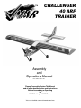
CHALLENGER
40 ARF
TRAINER
Assembly
and
Operations Manual
First Edition 1999 11 30
Please Thoroughly Review This Manual
and all other documentation and instructions
Before Assembling or Operating
the
VMAR Challenger 40ARF Trainer
Visit us on the Web at www.richmondrc.com/vmar
VMAR CHALLENGER 40ARF TRAINER
INTRODUCTION.
Liability Disclaimer
It is important that the following liability disclaimer be
READ BEFORE ASSEMBLING OR USING THIS PRODUCT
Thank you for purchasing a VMAR Product. VMAR
Manufacturing is committed to delivering superior value to
the RC modeller. Your new VMAR Challenger 40ARF
Trainer is a market leader in features, value, ease of use
and flexibility. Please review these instructions before
beginning the simple assembly procedure.
Model airplanes, model engines, model engine fuel, propellers and products such as the VMAR Challenger 40ARF
Trainer can be hazardous if improperly used. Be cautious
and follow all safety recommendations when using your
VMAR Challenger 40ARF Trainer. Keep hands, tools,
clothing and all foreign objects well clear of engines when
they are operating. Take particular care to safeguard and
protect your eyes and fingers and the eyes and fingers of
other persons who may be nearby. Use only a good quality
propeller that has no cracks or flaws. Stay clear of the
propeller and stay clear of the plane of rotation defined by
the propeller.
We’ve used metric measurements throughout these
instructions. We know that some of you like metric while
others think that furlongs per fortnight makes a nifty
velocity indicator. If you are in the furlongs camp, bear
with us… it’s not a big deal… 3 millimetres is stated as 3
mm and 3 mm is about 1/8 of an inch. Fire up your
confuser and you’ll find that 25.4 mm makes an inch. In
most cases we have listed both metric and imperial with the
imperial measurement in inches in brackets ( ).
The Manufacturer, Distributor, Retailer and/or other suppliers of this product expressly disclaim any warranties or
representations, either expressed or implied, including but
not limited to implied warranties of fitness for the purposes
of achieving and sustaining remotely controlled flight.
In no event will the Manufacturer, Distributor, Retailer and/
or other suppliers of this product have any obligation
arising from contract or tort, or for loss of revenue or profit,
or for indirect, special, incidental, consequential or other
damages arising from the use of this product.
In purchasing and/or using this product, the user accepts
all responsibility for its use and accepts all liability associated with such use.
Proceeding with assembly and
use of this product
indicates
Agreement With and
Acceptance of the Liability Disclaimer.
CAUTION.
A Remote Control Model Aircraft is not a toy. It is
a flying model that functions much like a full size
airplane. If you do not assemble and operate this
product properly you can cause injury to yourself and others and damage property. DO NOT
FLY this model if you are not qualified.
You are ultimately responsible for the mechanical, aeronautical and electrical integrity of this
model and it's structure, control surfaces,
hinges, linkages, covering, engine, radio, wiring,
battery and all other components. Check all
components before and after each flight. Don't fly
until it's right!
TM
Whenever we’ve used the directional terms left or right,
they are with respect to the Challenger when viewed as
you would from sitting in the cockpit... that is when viewed
from the back looking forward.
The Challenger 40 ARF Trainer from VMAR Manufacturing
carries on the VMAR tradition of offering beginners an easy
to fly, easy to assemble and top value 40 size ARF Trainer.
Simply put, the Challenger is the best quality, best value,
easiest to fly ARF trainer available anywhere! Nothing can
even come close to the Challenger for value!
Fantastic quality, outstanding graphic scheme and details,
unbeatable value, knock ‘em dead looks, more features and
a price you just cannot beat!
Your instructor will likely be looking for quality clevises on
your control surfaces. Most ARF’s use factory grade
clevises that leave you somewhat wanting in the confidence
department. Guess what? The Challenger uses VMAR metal
pin clevises on all control surfaces! You won’t be throwing
our clevises in file 13... you’ll be flyin ‘em with confidence in
your Challenger!
We’ve coupled those VMAR metal pin clevises to super strong
steel push rods that run in plastic tube guides all the way from
the tail to the radio compartment! Connections between the
threaded control rods and the servo arms are done with
custom VMAR metal pin clevises that have been designed to
accommodate the high angular rotation of the servo arms.
Nothing but nothing is going to break, bend, fail or otherwise
cause you grief between your servo’s and the tail feathers of
your Challenger! We've also included a servo tray. Not only
do we provide a servo tray but it is the best most universally
adjustable tray available anywhere. Once you see how our
servo tray works, you’ll be trying to buy ‘em as a part!
2
VMAR CHALLENGER 40ARF TRAINER
TM
INDEX.
Another feature that experienced RC flyers look for is
"pinned" hinges that don't rely solely on the hinge glue to
keep the control surfaces attached. Look no further. Turn
over a Challenger wing and look at the outboard and inboard hinges... yup, they're pinned! Double pinned in fact!
With steel pins to ensure the hinges are in to stay! Better
yet we've done all the end hinges on the rudder and elevator
as well! Check out other ARF trainers and you'll see how
rare this level of completeness is.
Liability Disclaimer and Caution
Page 2
Introduction
Page 2-3
Check Out the Contents
.
Check Off Tools & Shop Materials Needed
Page 4-5
Page 6
Check Off Other Items Needed to Complete Page 6
Don’t have a drill and tap system for installing your engine?
Relax, we’ve already done it for you by providing a cast
aluminum engine mount that has been pretapped and
comes with black allen head machine screws and engine
clamp straps. Check out how much a metal engine mount
costs in the store and you’ll wonder how we can do it! Put
your engine on the mount, line it up, cinch down the clamps
and you are done with the engine mounting stuff!
Check Off Optional Equipment & Access
Page 6
Notes (blank page)
Page 7
Wing Assembly
Page 8-11
Wing Servo Installation
Page 12-13
Installing the Main Landing Gear
Page 14-15
Installing the Nose Gear
Page 16-17
Installing the Fuel Tank & Battery Pack
Page 18-20
Installing the Engine
Page 20-21
Please check the "READ THIS FIRST" pamphlet included
with your kit for information about Troubleshooting, Contact
Procedures, Return Procedures and Conditions.
Installing the Horizontal Stabilizer
Page 22-23
Installing the Vertical Stabilizer
Page 24-25
If upon arrival of your model you noted damaged, missing
or defective components DO NOT proceed with assembly.
Installing the Radio
Page 26-29
Balancing
Page 30
Sealing the Fuel Tank into Position
Page 30-31
Functional Integrity
Page 31
Caution
Page 31
Replacement Parts
Page 31
More Information
Page 31
Copyright Notice
Page 31
Manual - Change Log
Page 31
Other VMAR Products.
Page 32
DAMAGED, MISSING or DEFECTIVE
ITEMS.
Damaged, missing or defective components must be
reported to your vendor within 30 days of purchase
and BEFORE any assembly begins. Please DO NOT
START if something is damaged, missing or defective.
Your vendor will not be able to provide you with
exchanges or replacements of parts that have been
assembled.
DO NOT START UNLESS IT'S RIGHT!
MANUAL - ERRORS AND OMISSIONS
This page was last updated 1999 11 30.
Please check the "READ THIS FIRST" pamphlet included
with your kit. Review any Errors or Omissions listed there
that may describe errors or omissions in this manual that we
discovered after the manual was printed but prior to your kit
being shipped.
Errors and Omissions.
Corrections to errors or omissions related to the
documentation and discovered after the initial printing
may be noted in a separate pamphlet entitled "READ
THIS FIRST"
Check our web site at www.richmondrc.com/vmar
for the latest information related to this product. Such information may include further tips or corrections to the documentation that we have added since your kit was shipped.
BEFORE PROCEEDING: Please check the READ
THIS FIRST pamphlet carefully for any Errors or
Omissions and take careful note of any references to
corrections or additional instructions.
3
VMAR CHALLENGER 40ARF TRAINER
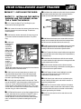
PHASE 1 - CHECK OUT THE CONTENTS.
TM
PLEASE SAVE YOUR BOXES UNTIL CHECK OUT COMPLETE
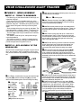
You’ve taken the lid off the box, read over the "READ ME FIRSTt" pamphlet and you are ready to start with the assembly
procedure… you’re about 6-8 hours away from being ready to go flying! Now is the time to look over what’s in the box. Please
go through the contents and make sure nothing has been damaged in shipping. Damaged, missing or defective components must be reported to your vendor BEFORE any assembly begins. Please DO NOT START if something is damaged, missing or defective. See Page 3 for further information. As you can imagine, once you join the wing halves or
install your radio or engine your options for returns are very limited. Your vendor will not be able to provide you with
exchanges or replacements of parts that have been assembled. DO NOT START UNLESS IT'S RIGHT!
R
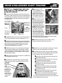
RSTEP 1.2 - CHECK OFF CONTENTS OF
THE MASTER BAG.
R
RSTEP 1.1 - CHECK OFF MAJOR
COMPONENTS INCLUDED.
Please read the "Read Me First" sheet before proceeding
any further.
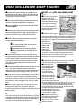
Open the Master Bag and carefully remove the contents.
Confirm that you have the followinging items. Do not open
the parts bags at this point, just check them off for now.
Ensure that you have the following major components. Do
not open the bags at this point... just look through the box
to ensure that you have the following major components.
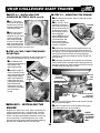
R 1 Right wing [WR]
R1 Fuel tank [FT]
R1 Spinner (nose cone) [SS] with screws
R1 Wing Parts Bag R1 Misc Parts Bag
R1 Main Gear Parts Bag R1 Nose Gear Parts Bag
R1 Control Horn Parts Bag
R 1 Left wing [WL]
WR
TOP OF RIGHT WING
R
RSTEP 1.3 - CHECK OFF CONTENTS OF
THE WING PARTS BAG.
WL
Open the Wing Parts Bag and carefully remove the
contents. Confirm that you have the following items and
then return them to the Wing Parts Bag.
BOTTOM OF LEFT WING
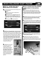
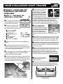
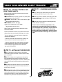
R1 Fuselage [FS] with the following
components that have been pre-installed in the fuselage:
REngine mount [EM ],
RElevator, rudder and nose gear control rods,
R2 piece throttle control rod [CRT] with collars [COL]
RUniversal adjustable servo tray [ST], [STDS],
[STSS], [STMS], [AW]
R2 EZ connectors [EZ] attached to the ends of the
nose gear push rod.
R2 Wing joint
dowels [WJD] 25
mm (1 in.) long,
wood
R4 Wing mounting
bolts [WB] made of
white plastic
R1 Small roll of
wing joint tape
[WJTW], white
R1 Small roll of wing joint tape [WJTY], yellow
R2 Aileron control rods with clevises at both ends [AC]
R1 Wing spar joiner [WJS] made of wood. Note: If the
Wing Spar Jointer [WJS] is not in the Wing Parts Bag it
will be have been shipped with one of the Wing halves.
FS
TV
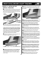
R1 Vertical stabilizer with
pre-installed rudder [TV]
R
RSTEP 1.4 - CHECK OFF CONTENTS OF
THE MISC PARTS BAG.
R1 Horizontal stabilizer
with pre-installed elevator
[TH]
TH
R1 Master Bag containing
parts & parts bags
Open the Misc Parts Bag and
carefully remove the contents.
Confirm that you have the following items and then return them to
the Misc Parts Bag.
TOP
BOTTOM
4
R2 Wooden guide blocks [WGB]
VMAR CHALLENGER 40ARF TRAINER
R
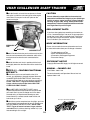
RSTEP 1.5 - CHECK OFF CONTENTS OF
THE MAIN GEAR PARTS BAG.
R
RSTEP 1.7 - CHECK OFF CONTENTS OF
THE CONTROL HORN PARTS BAG.
Open the Control Horn Parts Bag and carefully remove
the contents. Confirm that you have the following items
and then return them to the Control Horn Parts Bag.
R2 Metal bolts [CHB] 2.5 mm x 2530 mm (1 to 1-3/16 in.)
R 2 Plastic control horns [CHH]
R2 Plastic bevelled washers [CHW]
R2 Plastic T-nuts. [CHN]
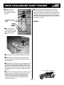
Open the Main Gear Parts Bag and carefully remove the
contents. Confirm that you have the following items and
then return them to the Main Gear Parts Bag.
R2 Ultralight treaded wheels 62 mm (2-7/16 in.) diameter [W]
R4 Wheel collars [COL] with set screws
R4 Sheet metal screws [MGMS] approx 15mm (5/8 in.)
long
R 2 Landing gear
straps [MGRS],
approx 9 mm x 21
mm
(3/8 x 7/8 in.) made
of white plastic with
a hole at each end.
R2 Pre-bent main
landing gear wires
[MG] approx 275
mm (11 in.) long
R
RSTEP 1.8 - CHECK OFF CONTENTS OF
THE SERVO TRAY PARTS BAG.
The Servo Tray Parts Bag is INSIDE THE FUSELAGE.
Undo the two securing screws and remove the servo tray
from the fuselage. Confirm that you have the following
items and then return them to the Servo Tray Parts Bag.
RUniversal adjustable servo tray [ST]
R2 black plastic adjustable slider plates, 1 long [STDS],
1 short [STSS], for mounting the servos
R9 small screws
[STMS]. 5 for mounting
the adjustment plates & 4
to mount the universal
servo tray to the fuselage.
R1 Allen wrench [AW]
for the screw in the preinstalled EZ connectors
R
RSTEP 1.6 - CHECK OFF CONTENTS OF
THE NOSE GEAR PARTS BAG.
Open the Nose Gear Parts Bag and carefully remove the
contents. Confirm that you have the
following items and then return them to
the Nose Gear Parts Bag.
R
RSTEP 1.9 - CHECK OFF LOOSE
MATERIALS PACKED IN THE BOX.
RYellow patch sheet
RWhite patch sheet
RAssembly and Operations Manual
R"READ ME FIRST" pamphlet
RListing of Accessories, Options & Spare Parts
R2 Wheel collars [COL] with set
screws
R1 Nose gear steering arm [SA] with
set screw
R1 Pre-bent metal nose gear wire [NG]
R1 Ultralight treaded wheel 62 mm
(2-7/16 in.) diameter [W]
Missing Something? Please See Page 3.
VMAR Challenger 40 ARF Parts Layout
NOTE:
- The elevator, rudder & steering push rods have been
pre-installed into the fuselage and are not shown here.
- Items ST, STDS, STSS, AW, and STMS are included in
the Servo Tray Bag and were temporarily installed in the
fuselage at the factory along with item CRT and two of
item COL.
- items EZ have been pre-installed on each end of the
pre-installed steering control rod at the factory.
- Items EM have been pre-installed in the fuselage at the
factory.
LEGEND:
- Items shown in the illustrations are flagged with legend
references in BOLD UPPER CASE and appear within
[SQUARE BRACKETS] throughout the manual. These
are not part numbers. Please refer to the attached Listing
of Replacement Parts, Tools & Accessories for Part
Numbers applicable in your market area.
TM
5
VMAR CHALLENGER 40ARF TRAINER
TM
R
RSTEP 1.11 CHECK OFF OTHER ITEMS
NEEDED TO COMPLETE CHALLENGER.
R
RSTEP 1.10 CHECK OFF TOOLS AND
SHOP MATERIALS NEEDED.
These tools & shop materials are not included and are
required to complete & operate your Challenger and most
other remote control aircraft. For some specific recommendations & part numbers please see the attached
listing of tools & materials available in your market area.
These items are not included and are required to complete
and operate your Challenger and most other remote
control aircraft. For specific recommendations and part
numbers please see the attached listing of items available
in your market area.
RClean and flat table or work surface approximately
RMedium fuel tubing appropriate for your choice of
600 x 1800 mm (24 x 72 in.)
R2.5 mm ball socket screwdriver or Allen wrench
R3.0 mm ball socket screwdriver or Allen wrench
R4.0 mm ball socket screwdriver or Allen wrench
RPhillips (cross head) screwdriver small size
RPhillips (cross head) screwdriver medium size
RFlat blade screwdriver medium size
RHeat gun for covering (optional for covering touch
up)
R30 Minute Epoxy and 240 grit sandpaper.
REpoxy mixing dishes, brushes and sticks
R Scissors
RMasking tape
RRuler or tape measure
R Side ("wire") cutters
RFlat file (optional)
R Pencil
RBall point pen
R Pliers
RHobby knife with #11 blade
RThin cyanoacrylate CA instant glue.
RSilicone based sealant
RCrescent wrench (optional)
RPaper towels
RRubbing alcohol
engine and fuel. 500-750 mm (24-36 in.)
R Liquid thread locker.
RRC FM radio with at least four channels of control
and on a frequency appropriate for your market area.
R Four servo's compatible with the RC FM radio.
Servos are generally sold with new radio systems.
RExternal switch actuator appropriate for your radio
system (optional).
REngine and muffler suitable for use in a remote
control model aircraft. A two stroke glow fuel .40-.53
cubic inch engine is recommended.
RPropeller suitable for the engine. See the engine
instruction manual for recommended diameter and
pitch.
REngine glow plug
REngine glow plug ignitor
REngine 4 way wrench
RFuel for the engine.
R"After Run" oil for engine.
RRC foam sheeting for wrapping radio receiver and
battery pack.
R
RSTEP 1.12 CHECK OFF OPTIONAL
EQUIPMENT AND ACCESSORIES.
These items are not included and are not required but
make the operation of your Challenger and most other
remote control aircraft easier & more enjoyable. For some
specific recommendations and part numbers please see
the separate listing of Accessories, Options & Spare Parts
available in your market area.
RPower Tote Deluxe field box #VMA-PT109D
RFuel pump and connecting tubing
RFueling valve
R Chicken stick or electric starter
RBattery to power electric starter
R Battery charger
RPower panel to manage starter and pump if
TM
electric.
6
RVMAR Model Engine Test Stand #VMA-ETS120.
RExtra propellers RExtra glow plugs
R Misc tools R 1/4 - 20NC tap
RStick on weights
VMAR CHALLENGER 40ARF TRAINER
NOTES
TM
NOTES
This page left intentionally blank
This page left intentionally blank
TM
TM
7
VMAR CHALLENGER 40ARF TRAINER
R
RPHASE 2 - WING ASSEMBLY.
R2.2.2 You will also need the following items that are not
included with your Challenger.
R
RSTEP 2.1 - TERMS TO REMEMBER
R Pencil R Masking tape.
- First the easy part, the outboard ends of the wings are
called the "wing tips".
- Each wing half has a flat wooden face that is at the
opposite end from the wing tips. This flat wooden face is
called the "wing root". We will be joining the wing halves
shortly and the wing roots will end up contacting each
other.
- The back edge of the wing can move up and down. The
moveable section is called an "aileron". The ailerons are
mounted to the "trailing edge of the wing" using hinges.
- The front edge of the wing is rounded and is called the
"leading edge".
- The "bottom" of the wing is flat, the top of the wing is
curved to provide lift.
- The "wing spar joiner" is a slightly V shaped piece of
wood that will serve to join the wing halves together and
provide strength to the wing when in the air.
R2.2.3 Remove the wing halves [WL] and [WR] from
the plastic bag they were shipped in. Examine the wing
halves carefully before proceeding.
R2.2.4 Remove the protective tape and cardboard that
has been applied to the wire like aileron horns. These are
found near the wing roots. Peel the protective tape away
carefully.
R2.2.5 Place the wings top side up on a table so that
the leading edge ("front") of the wing is away from you
and the ailerons are towards you. Position the left wing to
the left and the right wing to the right so that the wing
roots are facing each other.
R2.2.6 Position the wing so that the ailerons and white
plastic aileron horns are hanging over the edge of the
table allowing the wing halves to lie flat on the table
surface with the yellow side of the wing facing down.
R
RSTEP 2.2 - DRY ASSEMBLY OF THE
WING HALVES.
R2.2.7 Locate the two short wing joint dowels [WJD].
You will first be assembling the wing with no glue. We call
this a "dry assembly" and it is important to use no glue
until you have done the dry assembly to check everything
out.
TOP OF RIGHT WING
TM
Mark a centre line around each dowel with the pencil.
Insert a dowel into the hole in the left wing root that is
located closest to the leading edge of the left wing. Push
the dowel into the hole up to the half way mark denoted by
the pencil line.
WR
LEADING
EDGE
VIEW OF LEFT
WING ROOT
WL
DOWEL
INSERTED
TO HALF
ITS
LENGTH
BOTTOM OF LEFT WING
TRAILING
EDGE
AILERON
HORN
R2.2.8 Insert the second wing joint dowel into the hole in
R2.2.1 To dry assemble the wing you will need the right
the left wing root that is located closest to the trailing edge
of the left wing. Push the dowel into the hole up to the half
way mark denoted by the pencil line.
R2.2.9 Examine the wooden wing spar joiner [WJS].
Note that it is not straight. It has a slight V shape. Mark
a centre line at the apex of the V with a pencil. When
the wing spar joiner looks like a broad V it is right way
up. If the wing spar joiner looks like a broad upside down
V it is the wrong way up and should be turned over.
Pencil in arrows pointing up on both sides of the wing
spar joiner
wing half [WR] and the left wing half [WL] as shown
above and the following items from the Wing Parts Bag.
R 1 Wing spar
joiner [WJS]
made of wood
R 2 Wing joint
dowels [WJD]
25 mm (1 in.)
long, wood
R 4 Wing
mounting bolts
[WB] made of white plastic
INSERT INTO WING HALVES SO THAT WING TIPS
ARE HIGHER THAN CENTRE WHEN WING UPRIGHT
LEFT
8
UP
WJS
UP RIGHT
MARK CENTRE LINE & "UP" ARROWS WITH PENCIL
VMAR CHALLENGER 40ARF TRAINER
TM
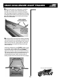
R2.2.10 Check the entrance to the wing spar joiner
R2.2.15 Carefully and firmly slide the right wing towards
cavity in the wing roots. There may be "flashing" or a thin
skin of wood covering the entrance to the cavity which
should be removed carefully with a sharp hobby knife.
the left. Wiggle the wings slightly to encourage the two
wing alignment dowels to mate with their respective
receiving holes in the opposite wing root.
R2.2.11 Holding the wing spar joiner in your right hand
R2.2.16 Carefully and firmly continue to slide the right
and right way up like a broad V slide the wing spar joiner
firmly and carefully into the wing spar joiner cavity
("hole") in the root of
the left wing. Push
firmly and carefully
until the wing spar
joiner is inserted into
WING SPAR
the left wing up to the
JOINER CAVITY
pencil mark at the apex
(rectangular hole in wing root)
of the V.
wing towards the left until the wing roots touch. Push the
wing halves firmly together and apply masking tape
across the joint to keep the wing roots aligned and firmly
in contact with each other. Apply masking tape top and
bottom and along the joint.
R2.2.17 Continue working with the wing turned over so
that you are looking at the bottom of the wing with the
leading edge facing away from you and the ailerons
closest to you.
R2.2.18 Take the fuselage [FS] out of it's protective bag
RIGHT END
OF WING
SPAR
JOINER
WIN
GS
PA
LEFT
WING
TOP SIDE
UP
RJ
OIN
and locate four of the plastic wing bolts [WB] from the
wing parts bag. Lubricate the wing bolts with a light
grease or a very light coating of candle wax and screw
the bolts into the wing mounting blocks in the fuselage.
Go slowly, winding the bolts in a bit, back them out, add a
bit more lube and then screw them in further in stages.
You will note that it becomes easier as you go. Using a 4
way wrench on the socket heads of the bolts makes it
easier but a flat bladed screw driver will do the job.
ER
R2.2.12 Holding the left wing firmly in place on the
WING BOLTS
table with the top side up, take the right wing and carefully position the right wing spar joiner cavity onto the
end of the wing spar joiner protruding from the left wing.
R2.2.13 Turn the wing halves over so that you are looking
at the bottom of the wing halves with the leading edge facing
away from you and the ailerons closest to you.
R2.2.14 Slide the right wing firmly and carefully onto
the wing spar joiner until the wings are about 25 mm (1
in.) apart. Stop at this point and examine the wing assembly. You should see that the wing when bottom side
up, takes on a slight inverted V shape with tips sweeping
downwards. You should also note that the two short wing
alignment dowels are lining up with two receiving holes in
the opposite wing root.
If the wing bolts appear to be unduly tight in the blocks
when you try to screw them in, do not force the issue.
Back the bolts out and “chase” the threads in the
mounting blocks with a 1/4-20 NC tap. You can purchase
these at most hardware stores or visit your local hobby
retailer. Thread the tap lightly and gently into the threaded
holes and twist it carefully until it engages with the
threads and then turn the tap through the block and back
it out again.
ALIGNMENT DOWEL
RIGHT WING
VIEWED
FROM
BOTTOM
WING SPAR
JOINER
ALIGNMENT
DOWEL
R2.2.19 Remove all the wing bolts from the fuselage.
LEFT WING
VIEWED
FROM
BOTTOM
R2.2.20 Examine the four wing bolt holes in the wing.
Use a sharp hobby knife to carefully cut away the covering
that has been applied over the holes on the bottom of the
wing.
9
VMAR CHALLENGER 40ARF TRAINER
R
RSTEP 2.2 - DRY ASSEMBLY OF THE
WING HALVES cont'd.
R2.2.21 Place the wing right way up in the wing saddle
TM
R2.3.5 To assemble and glue the wing you will need the
two wing halves [WR] and [WL] and the following items
from the Wing Parts Bag.
R 1 Wing spar
area of the fuselage. Place the four wing bolts into the
wing bolt holes in the top of the wing and make sure you
can screw them down into the wing bolt mounting blocks
in the fuselage.
joiner [WJS]
made of wood
R 2 Wing joint
dowels [WJD]
25 mm (1 in.)
long, wood
R1 Small roll of
wing joint tape
[WJTW], white
R1 Small roll of wing joint tape [WJTY], yellow]
WING
FUSELAGE
R2.3.6 You will also need the following items that are not
included with your Challenger.
R2.2.22 Unscrew the wing bolts from the fuselage
R30 Minute Epoxy parts A and B
RSandpaper (Coarse 240 grit recommended)
R Epoxy brush and R Stir sticks
RDisposable mixing dish for the epoxy
RPaper towels RRubbing alcohol
RHobby knife RMasking tape.
blocks and remove the wing from the fuselage.
R
RSTEP 2.3 - GLUING THE WING HALVES
R2.3.1 Before gluing the wing halves together, dry
assemble everything as outlined in the preceding step. It
is critical that you dry assemble the wing halves before
you begin to use epoxy. Remember, you've got one
chance to get it right! Be careful and get things straight
the first time! If you have not dry assembled the wing as
outlined in the previous steps, stop now and go back and
do the dry assembly before proceeding beyond this step.
USE 30 MINUTE EPOXY!
Use 30 Minute Epoxy to glue the wing together. Use
only epoxy with a cure time of 30 minutes. Faster
cure time epoxy will not allow you time to correctly
position the parts before it begins to cure. 30 Minute
Epoxy also provides a stronger bond than faster cure
epoxy and you want the strongest bond you can get.
R2.3.2 After you have done the dry assembly and test
bolted the wing to the fuselage to confirm that everything
fits together, it is time to disassemble the dry assembled
wing. Carefully remove the masking tape and pull the wing
halves apart. Use short rocking and gentle twisting
motions when pulling the wings slightly apart.
R2.3.7 Using coarse sandpaper, lightly sand all sides of
the wing spar joiner, the wing alignment dowels and the
faces of both wing roots.
R2.3.3 Use a pencil to carefully mark both wing roots
R2.3.8 Using a disposable mixing dish and stir sticks,
with an arrow pointing up and check that you have previously marked both faces of the wing spar joiner with an
arrow pointing up so that the wing can be easily reassembled correctly.
thoroughly mix up a batch of 30 Minute Epoxy according
to the instructions that came with the epoxy.
R2.3.9 Using a disposable epoxy brush, apply the 30
R2.3.4 Completely separate the wing halves and remove
Minute Epoxy liberally to all sides of one end half of the
wing spar joiner [WJS] and use the joiner to work the 30
Minute Epoxy into both of the wing spar joint cavities.
Apply more epoxy to the one end of the wing spar joiner
as you work epoxy into the second wing spar joint cavity.
It is important to work 30 Minutes Epoxy into the wing spar
joint cavities of the left and right wings. Don't scrimp on
the epoxy! Use lots.
the two short wing alignment dowels and the wing spar
joiner. Set the dowels and joiner aside for now.
10
VMAR CHALLENGER 40ARF TRAINER
R2.3.10 Insert the end of the wing spar joiner that is cov-
TM
ered with glue into the wing spar joiner cavity of the left wing
up to the pencil line on the wing spar joiner. Make sure the
wing spar joiner is right way about.
R
RSTEP 2.4 - APPLYING WING JOINT
TAPE.
R2.4.1 Using the yellow
YELLOW WING JOINT
R2.3.11 Apply 30 Minute Epoxy to the two dowel receiving
TAPE
[WJTY]
holes in the wing roots of both the left and right wings.
R2.3.12 Apply 30 Minute Epoxy to one half end of the two
wing dowels [WJD].
R2.3.13 Insert the epoxy end of the two wing dowels into the
dowel receiving holes in the left wing. Insert the dowels into
the wing root of the left wing up to the pencil lines on the
dowels.
roll of wing joint tape
[WJTY] and scissors trim
the width at one end of the
tape so that it is about 22
mm (7/8 in.) wide and can
pass clearly between the
aileron torque rods on the
bottom of the wing.
R2.4.2 Peel away about 75
R2.3.14 Carefully, thoroughly and quickly use an epoxy
brush to apply 30 Minute Epoxy to:
RBoth sides and both edges of the wing spar
joiner protruding from the wing root of the left wing.
Use lots of 30 Minute Epoxy.
RThe protruding ends of the wing joint dowels.
RThe wing roots of both (yes both!) the left and
right wings.
R2.3.15 Carefully slide the right wing onto the end of the
wing spar joiner protruding from the root of the left wing. Make
sure the wing spar joiner is oriented correctly so that when
the wing is top side up the wing tips are rising as you move
away from the centre of the wing. Check the arrows you
pencilled in earlier.
R2.3.16 Slide the wings together until they are about 75 mm
(3 in.) apart. Check things out carefully. Make sure the
dowels are in place in the left wing root and that the two wings
are both facing up and the wing spar joiner is right way up.
R2.3.17 Slide the wings tightly together so that the wing
roots touch and epoxy squeezes out between the wing
roots to confirm that the roots are touching and that the 30
Minute Epoxy is still wet enough to flow and give a good
bond.
R2.3.18 Using a paper towel, moistened with a bit of
rubbing alcohol, wipe away any excess epoxy that
squeezes out between the wing roots and align the top and
bottom surfaces.
R2.3.19 Hold the wing roots tightly together for at least 1
hour using masking tape straps across the joint on the top
and bottom of the wing. Apply masking tape along the top
and bottom joint to trap the epoxy in place and prevent it
running out of the joint before the epoxy cures.
11
CUT TAPE TO REDUCE
WIDTH TO CLEAR
AILERON TORQUE RODS
mm (3 in.) of the backing
material from the trimmed end and apply the yellow tape to
the underside of the wing such that the tape straddles the
wing joint seam. Keep the tape centred across the seam.
Work forward
YELLOW WING JOINT TAPE [WJTY]
from the trailing
edge towards the
leading edge,
peeling away
AILERON SERVO CAVITY
more of the
backing material
as you go. At all times keep the tape centred over the
wing seam and keep tension on the tape. Rub the tape
with your hand or a soft cloth to tack it down. Trim the
length to fit just short of the leading edge.
R2.4.3 Re-open the aileron servo cavity by using your
hobby knife to neatly cut away the trim tape.
R2.4.4 Using the
white roll of wing joint
tape [WJTW], peel
away about 75 mm (3
in.) of the backing
material & apply the
WHITE WING
tape to the top side of
JOINT TAPE
[WJTW]
the wing such that the
tape straddles the wing
joint seam. Keep the
tape centred across the seam.
Start on the bottom of the wing about 25 mm (1 in.) back
from the leading edge and work up and over the top
surface of the wing towards the trailing edge, peeling
away the backing material as you go. At all times keep
the tape centred over the wing seam
and keep tension on the tape.
Rub the tape with your hand or a
soft cloth to tack it down.
R 2.4.5 Work back to the
trailing edge and then around
the trailing edge to cover
about 12 mm (1/2 in.) of the
bottom of the wing.
VMAR CHALLENGER 40ARF TRAINER
R
RSTEP 2.5 - INSTALLING THE AILERON SERVO INTO THE WING.
R2.5.1 To install the aileron servo into the wing you will
need the following items:
R Servo
RServo mounting screws and grommets as
supplied with the servo
RServo control arm as supplied with the servo
RTwo aileron control rod [AC] assemblies from
the wing parts bag. The assemblies consist of a
metal rod with a plastic clevis screwed onto each
end.
RMasking tape. RPhillips Screwdriver.
TM
R
RSTEP 2.6 INSTALLING THE AILERON
CONTROL RODS TO THE AILERON
SERVO.
R2.6.1 Consult your radio instruction manual and
centre the aileron servo by plugging it into the aileron
channel in the receiver. Turn on the transmitter and then
the receiver. Centre the aileron trim lever on the transmitter. Remove the servo arm mounting screw & the servo
arm.
R2.6.2 Mount the servo arm back on the servo. Position
the arm to be parallel with the back edge of the wing.
Screw the arm into place with the servo arm mounting
screw supplied with the servo.
R2.6.3 Locate the two aileron control rods [AC] in the
.
hardware bag. Ensure the clevises are screwed well onto
the threaded portions of the rod. Rotate and tug aggressively on the clevises and ensure that they are not loose
on the rods.
AILERON CONTROL RODS
AC
AILERON CONTROL RODS
CLEVIS
AC
R2.5.2 Turn the wing upside down. Trial fit the aileron
CLEVIS
servo into the servo-mounting cavity located in the centre
of the bottom of the wing. The cavity straddles the wing
joint. You may have to modify the cavity slightly to provide
clearance for the servo and servo wires. Use a hobby
knife to modify the cavity as required. Most servos have
their wire exit guide protruding from one end. Position
your servo so that the wire exit guide is closest to the
leading edge. The servo cavity in the wing has extra room
at the end of the cavity closest
to the leading edge to accomLEADING EDGE
modate the servo wiring.
R2.6.4 Tape the ailerons into their neutral position so
that they are even with the trailing edge of the wing and
not pointing either up or down.
R2.6.5 Ensure that the aileron control horns are
screwed onto the threaded aileron torque rods that
protrude from the wing and that both control horns are in
approximately the same place on their respective torque
rods.
R2.5.3 Screw the servo into
place with the screws and
grommets supplied. It is
important to install the grommets and screws correctly.
See the manual that came with
your radio for instructions
about your particular servo
grommets. Fasten the screws
down according to the manufacturers recommended
tightness.
SERVO
SERVO
ARM
SERVO
AILERON
CONTROL
HORN
AILERON
CONTROL
HORN
TRAILING EDGE
12
AILERON
TR
TORQUE
ROD
AI
LI
NG
ED
GE
VMAR CHALLENGER 40ARF TRAINER
R2.6.6 Connect the
R2.6.12 If when doing the tests noted in 2.6.10 and
LEADING EDGE
SERVO
ARM
CLEVIS
clevises on the aileron
control rods to the aileron
servo arm.
TM
2.6.11 the direction of aileron deployment is incorrect,
consult your radio manual for how to reverse the direction
of rotation of your servo. Control surface movement and
alignment will be checked again during final setup but it is
a good idea to set things up properly as you go along with
the assembly of your kit.
SERVO
AILERON CONTROL
RODS
NOTES
AILERON
CONTROL
HORN
CLEVIS
R2.6.7 Connect the
clevises on the other end
of the aileron control rods
to the aileron control
horns.
TRAILING EDGE
LEADIN
G EDG
E
CLEVIS
SERVO
TR
AI
LI
NG
CLEVIS
ED
G
E
AILERON
CONTROL
HORN
R2.6.8 Remove the masking tape holding the ailerons.
R2.6.9 Turn on your radio and activate the ailerons
using the aileron stick and ensure a smooth full motion
can be achieved.
R2.6.10 With the wing top side up and viewed from the
back, ensure that moving the transmitter aileron stick to
the left raises the left aileron and lowers the right aileron.
Movement of the stick to the left will roll the aircraft to the
left (counter clockwise roll of the wing when viewed from
the back).
This space left intentionally blank
R2.6.11 With the wing top side up and viewed from the
back ensure that moving the transmitter aileron stick to
the right raises the right aileron and lowers the left
aileron. Movement of the stick to the right will roll the
aircraft to the right (clockwise roll of the wing when
viewed from the back).
TM
13
VMAR CHALLENGER 40ARF TRAINER
R
RPHASE 3 - INSTALLING THE
LANDING GEAR.
TM
R
RSTEP 3.2 - CHALLENGER MAIN LANDING GEAR INSTALLATION.
The Challenger has a tricycle gear configuration ("trike
gear") using a steerable nose wheel and main landing
gear. Trike gear is recommended in trainers and makes it
much easier to steer your model on the ground and to
control it during take off.
The main landing gear must be assembled before it can
be installed. See Step 3.1 if you have not yet assembled
the main landing gear.
R
RSTEP 3.1 - CHALLENGER MAIN LANDING GEAR ASSEMBLY.
R3.1.1 To assemble the main landing gear you will need
you will need the fuselage [FS], the
main landing gear assemblies from Step
3.1 and the following items from the
Main Gear Parts Bag.
R3.2.1 To install the main landing gear
the following items from the Main Gear Parts Bag.
R4 Sheet metal screws
R2 Ultralight
[MGMS] approx 15 mm (5/8 in.)
long
R2 Landing gear straps
[MGRS], approx 9 mm x 21 mm
(3/8 x 7/8 in.) made of white
plastic with a hole at each end.
treaded wheels
62 mm (2-7/16
in.) diameter
[W]
R 4 Wheel
collars [COL]
with set screws
R 2 Pre-Bent
Main Landing
Gear Wires [MG] approx 275 mm (11 in.) long
You will also need the following items that are not included
with your Challenger.
RTape measure RPhillips screw driver
You will also need the following items that are not included
with your Challenger.
R3.2.2 Turn the fuselage [FS] over and examine the
bent main landing gear wires.
bottom of the fuselage carefully. Measure back about 285
mm (15 in.) from the front of the fuselage and locate four
small holes in the covering on the bottom of the fuselage.
There may also be a sticker on the bottom of the fuselage
just forward of the four holes. If the sticker is present it will
say "MAIN LANDING GEAR LOCATION".
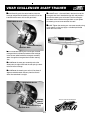
R3.1.4 Place one of the ultralight treaded wheels [W] on
R3.2.3 Using your fingers, feel for a slot underneath the
the pre-bent main landing gear wires.
covering. The slot runs across the bottom of the fuselage
from side to side and lies between the four small holes.
RLiquid thread locker RPhillips screw driver
R3.1.2 Locate both of the pre-bent main landing gear
wires [MG]
R3.1.3 Place one of the wheel collars [COL] on the pre-
R3.1.5 Install a second wheel collar [COL] on to the prebent main landing gear wires. Leave enough of a gap to
allow the wheel to rotate freely.
FRONT
MAIN GEAR
MOUNTING LOCATION
R3.1.6 Apply liquid thread locker and securely tighten the
set screws in each wheel collar.
PRE-BENT MAIN
LANDING GEAR
WIRE [MG]
(Tip: file flats on the
axle where the wheel
collar set screws contact
the axle. The set screws will
stay tighter longer. Apply
liquid thread locker to the set
screws)
SET SCREWS
VIEW OF BOTTOM OF FUSELAGE
WHEEL [W]
R3.2.4 Use a sharp blade in your hobby knife and
carefully remove the covering that obscures the slot in the
fuselage. Do not cut into the wood... just remove the
covering. If you inadvertently cut into the wood, seal the
cut line with CA glue.
R3.2.5 The slot has a hole at each end. Look carefully
WHEEL COLLER [COL]
14
and you will notice one hole is close to the back edge of
the slot and the other hole is close to the front edge of the
slot. These two holes and the slot will be used to install the
main landing gear assemblies that you built in Step 3.1
VMAR CHALLENGER 40ARF TRAINER
TM
NOTES
R3.2.6 Locate the two main landing gear assemblies
from Step 3.1 Carefully insert the wire end of each
assembly into the holes at the end of the landing gear
slots. We suggest rotating the assemblies back and forth
and wiggling the wire down into the holes until the landing
gear is just slightly away from contacting the fuselage.
See the illustration below.
MAIN LANDING
GEAR ASSEMBLIES
SLOT IN
BOTTOM OF
FUSELAGE
FUSELAGE [F]
BOTTOM VIEW
LOOKING BACK
FROM FRONT.
R3.2.7 Consult the illustration below before proceeding.
Then rotate the two main landing gear assemblies so that
they line up with the slot in the fuselage. Press the wire
down firmly into the slots. Tapping with the handle and
then the blade of a screwdriver will help seat the gear
wires into the slot.
Install the 2 landing gear straps [MGRS], approx 9 mm x
21 mm (3/8 x 7/8 in.) made of white plastic with a hole at
each end using the 4 sheet metal screws [MGMS]
approx 15 mm (5/8 in.) long and a Phillips screw driver.
Turn all the screws in evenly a small increment at a time.
Tap on the gear wires as you go until the screws are
firmly holding the straps in place and the straps are
holding the gear wires firmly into the slot in the fuselage.
MAIN LANDING
GEAR ASSEMBLIES
This space left intentionally blank
TM
LANDING GEAR STRAPS
[MGMS] AND SHEET
METAL SCREWS [MGMS]
15
VMAR CHALLENGER 40ARF TRAINER
R
RSTEP 3.3 - CHALLENGER NOSE GEAR ASSEMBLY.
TM
R
RSTEP 3.4 - CHALLENGER NOSE GEAR INSTALLATION.
R3.3.1 To assemble the nose gear
The nose gear must be assembled before it can be
installed. See Step 3.3 if you have not yet assembled the
nose gear.
you will need the following items from
the Nose Gear Parts Bag.
R3.4.1 To install the nose gear you will need the fuse-
R2 Wheel collars [COL] with set
lage [FS], the nose gear assembly from Step 3.3 and
screws
R1 Pre-bent metal nose gear wire
[NG]
R1 Ultralight treaded wheel 62 mm
(2-7/16 in.) diameter [W]
R1 Nose gear steering arm
[SA] with set screw from the
nose gear parts bag.
R2 EZ connectors [EZ] that
were pre-installed on each
end of the steering arm
control rod.
R1 Allen wrench [AW] for
the screw in the pre-installed
EZ connectors
You will also need the following items that are not included
with your Challenger.
RLiquid thread locker RPhillips screw driver
R3.3.2 Locate the pre-bent metal
You will also need the following items that do not come
with your Challenger.
nose gear wire [NG]
R3.3.3 Place one of the wheel
RPhillips screw driver RLiquid thread locker
collars [COL] on the pre-bent nose
gear wire.
R3.4.2 Locate the nose gear steering arm and back off
R3.3.4 Place the ultralight treaded
the steering arm set screw.
wheels [W] on the pre-bent nose
gear wire.
R3.4.3 Turn the fuselage over and locate the steering
R3.3.5 Install the second wheel
control rod protruding from the firewall. Pull the control rod
forward so that you have a bit of room to work.
collar [COL] on to the pre-bent nose
gear wire. Leave enough of a gap to
allow the wheel to rotate freely.
R3.4.4 Using the Allen wrench from the Servo Tray Parts
Bag, remove the pre-installed EZ connector from the end
of the steering arm control rod and after consulting the
illustration below, install the EZ connector on to the nose
gear steering arm. Tighten the retaining nut securely.
R3.3.6 Apply liquid thread locker
and securely tighten the set screws
in each wheel collar.[COL]
R3.4.5 Connect the steering control rod to the EZ
connector as shown below. Tighten the Allen screw
securely using the Allen wrench and a touch of liquid
thread locker.
STEERING ARM [SA]
SLEEVE TUBE
MAIN GEAR AND WHEELS
NOSE GEAR AND WHEEL
16
STEERING
CONTROL ROD
EZ CONNECTOR [EZ]
VMAR CHALLENGER 40ARF TRAINER
TM
R3.4.6 Carefully push the control rod back into the
R3.4.10 There is a flat notch filed in the front face of the
fuselage and position the steering arm so that it can be
inserted into the recess in the nose gear block.
nose gear wire that is intended to align with and provide a
seat for the steering arm set screw. Push the nose gear
wire down further into the nose gear block as you tighten
the steering arm set screw onto the flat notch.
NOSE GEAR BLOCK
R3.4.11 Tighten the steering arm set screw securely using
a ball wrench or allen key. Apply a suitable liquid thread
locker to the set screw.
Z-BEND
WIRE
STEERING ARM [SA]
CONTROL ROD
R3.4.7 Slide the steering arm into the pre-installed
nose gear block and from the bottom of the fuselage,
insert the non-wheel end of the nose gear assembly
down through the nose gear block and the steering
arm.
STEERING ARM
WITH SET SCREW
R3.4.8 Rotate the nose gear assembly so that the
wheel points straight ahead and the coil spring is closer
to the tail of the fuselage.
R3.4.9 Rotate the steering arm so that it lies about 5
degrees rotated forward and away from the firewall
when the nose wheel is straight.
NOSE GEAR BLOCK
NOSE GEAR
STEERING
ARM SET
SCREW
This space left intentionally blank
TM
STEERING ARM [SA]
CONTROL ROD
17
VMAR CHALLENGER 40ARF TRAINER
R
RPHASE 4 - THE FUEL TANK &
RECEIVER BATTERY PACK.
TM
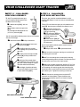
R4.1.5 Push the stopper firmly into the neck of the tank
until the shoulder of the black stopper contacts the neck
of the tank.
The fuel tank is shipped in the Master Parts Bag. The
pre-bent metal fuel outlet tubing, fuel stopper, cinch
bolt and plastic retaining disks have been pre-assembled and inserted into the neck of the tank. The fuel
clunk has also been placed into the tank.
R4.1.6 Ensure that the
external metal tubes are
pointing upwards as
depicted here and then
tighten the cinch bolt in
the centre of the stopper
until the external plastic
disk begins to dimple
inwards.
R
RSTEP 4.1 - ASSEMBLING THE FUEL
TANK.
R4.1.1 To assemble the fuel tank you will need the
following items included with the kit:
RThe fuel tank [FT]
RThe pre-assembled stopper and pre-bent metal
R4.1.7 Attach a loose
piece of tubing to each of the external metal tubes. Pinch
one closed while blowing into the other. You should see
the tank bulge slightly under pressure. Listen for air
escaping while you continue to blow and keep the tank
pressurized. If you hear any air leaking from around the
stopper, back off the cinch bolt slightly, rotate the stopper
slightly to and fro and then re-tighten the cinch bolt
slightly more securely. Test with air pressure again.
fuel tubing assembly shipped inserted in the tank.
RClunk (shipped inside the tank)
You will also need the following items not included with the
kit:
R100 mm (4 in.) of medium fuel tubing suitable for
your fuel type
R50 mm (2 in.) of medium fuel tubing suitable for
your fuel type. If possible select a different colour
for this piece
RPhillips screw driver
R4.1.8 Hold the tank with the stopper end pointing
upwards. Back light the tank assembly with a strong light
from behind. You should see a ghost like image of the
tubing and the clunk. Ensure the tubing has stayed
oriented as per the cutaway depiction of step 4.1.4 and
that the clunk swings freely to and fro when you move the
tank from side to side. While holding the tank vertically
with the stopper end upwards, the clunk should be approximately 10 mm (3/8 in.) from the end of the tank
opposite the stopper.
R4.1.2 Remove the stopper assembly from the tank and
extract the clunk.
R4.1.3 Using the 100 mm (4 in.) and the 50 mm (2 in.)
pieces of tubing and the stopper assembly, assemble the
tubing, stopper assembly and clunk as shown below. Note
that the 100 mm (4 in.) piece of fuel tubing is applied to
the straight end of one of the metal tubes and the clunk is
inserted into the other end of the medium fuel tubing.
R
RSTEP 4.2 - INSTALLING THE FUEL
TANK.
STOPPER & PRE-BENT METAL FUEL
TUBING ASSEMBLY
MEDIUM FUEL
TUBING
R4.2.1 Before installing the fuel tank into your Chal-
CLUNK
lenger, please note that:
- One of the pre-bent metal tubes will supply fuel to the
engine and allow you to fill the tank up. We call this the
"Fuel Line".
- The other pre-bent metal tube will be connected to the
muffler of your engine and serves to bring engine pressure into the tank to help force fuel out the fuel line into
the engine. We call this line that is normally connected to
your muffler the "Pressure Line". It also serves as a fuel
overflow vent when topping the tank up with fuel.
R4.1.4 Insert the clunk and tubing assembly into the fuel
tank such that the external pre-bent metal tubes are both
pointing up and the tubing inside is oriented as illustrated
in the cutaway depiction shown below.
18
See the following depiction that illustrates the location and
orientation of the fuel and pressure lines.
VMAR CHALLENGER 40ARF TRAINER
TM
R4.2.4 Trial fit the tank
by inserting it from within
the fuselage radio
compartment, stopper
end first with the metal
tubes pointing up and
pushing the tank gently
FUEL
forward until the metal
TANK
tubes and stopper pass
STOPPER
through the firewall.
Adjust the angle of the
metal tubes so that they
still point upwards and
clear the firewall with
sufficient clearance to
allow you to push the
fuel tubing on to and
over the metal tubes.
R 4.2.5 When you are
satisfied with the fit of the tank and the metal tubing,
we suggest also trial fitting your engine and ensuring
that the tank metal tubing clears the back of the
engine with sufficient clearance.
The "Fuel Line" will supply
fuel to the engine and
allow you to fill the tank up
R4.2.6 Remove the tank and place about 50 mm (2
in.) of medium tubing over the metal tubes so that the
tubing temporarily joins the metal tubes and seals
them off against dust, debris and sealant.
The "Pressure Line" is connected to the muffler of your
engine and serves to bring engine pressure into the tank
to help force fuel out the fuel line into the engine. It also
serves as a fuel overflow vent when topping the tank up
with fuel.
You will temporarily reinstall the tank again in Step
4.4 after locating the battery pack and then finally
seal the tank into position in Step 8.2 after balancing
the aircraft and getting the CG right.
fuselage [FS].
R4.2.3 Locate the two
piece throttle control rod
[CRT] that was shipped
attached to the Servo Tray
Parts Bag. Loosen the
collar set screws and
separate the two rods.
From the front, insert one
of the control rods, metal
end first through the hole in
the right side of the firewall
and back through the right
hand side of the tank
compartment and through
the hole in the bulkhead
separating the tank and
radio compartments.
FIR
EW
AL
L
R4.2.2 Remove the Servo Tray Parts Bag from the
R
RSTEP 4.3 - INSTALLING THE
RECEIVER BATTERY PACK.
THROTTLE
CONTROL
ROD
R4.3.1 Consult your radio manual for instructions
about hooking up your receiver battery, receiver and
switch harness.
R 4.3.2 We recommend locating the
battery under the fuel
tank before the fuel
tank final install is
completed.
BATTERY WRAPPED
IN FOAM
R 4.3.3 Wrap the
THROTTLE
CONTROL
ROD
19
battery pack securely in
foam suitable for RC
equipment and wrap the
foam insulated pack in a
plastic bag or cling wrap. Immobilize the pack from
moving side to side or front to back with chunks of foam.
VMAR CHALLENGER 40ARF TRAINER
R
RSTEP 4.3 - INSTALLING THE
RECEIVER BATTERY PACK cont'd.
TM
R
RSTEP 5.1 - MOUNTING THE ENGINE.
R5.1.1 Remove the muffler, prop nut and prop washer
from your engine.
R4.3.4 Thread the
R5.1.2 Use a 4 mm
battery pack connector
and wire back from the
fuel compartment to the
radio compartment.
socket ball wrench or
Allen wrench to remove
the four black machine
screws that work with
the clamping plates on
the metal engine
mounts [EM] that have
been pre-installed into
your Challenger. Set
the machine screws
and the clamping plates
aside for a moment.
R4.3.5 Later you will
hook up the battery
connector to your radio
system according to
your radio instruction
BATTERY PACK
manual. For now tape it
CONNECTOR
down to the floor of the
radio compartment with
masking tape to keep it out of the way.
MACHINE
SCREWS
CLAMPING
PLATES
ENGINE
MOUNTS
R5.1.3 Position the engine on the engine mounts and
R
RSTEP 4.4 FUEL TANK TEMPORARY
RE-INSTALL.
confirm that the fuel tank metal tubes clear the back of
the engine. Trial fit the engine temporarily into place with
the four black machine screws and clamping plates.
Tighten the screws only enough to tack the engine into
place for now.
After completing the installation of your receiver battery
pack you should temporarily re-install the fuel tank.
R5.1.4 Check the position of the engine on the engine
R4.4.1 Remove the
mount and ensure that the two metal clamping plates are
above the engine lugs and that the black machine screws
straddle the engine lugs two to a side.
protective fuel tubing that
you applied to the
external metal pipes
R4.4.2 Re-install the
tank by inserting it from
within the fuselage radio
compartment, stopper
end first with the metal
tubes pointing up and
pushing the tank gently
forward above the
battery pack until the
metal tubes and stopper
pass through the
firewall.
FUEL
TANK
STOPPER
THROTTLE
ARM
THROTTLE
CONTROL ROD
CLEVIS
MACHINE SCREW
ENGINE
MOUNT
[EM]
CLAMPING
PLATE
ENGINE
LUG
SIDE VIEW OF TYPICAL
MOUNTING
CONFIGURATION
R5.1.5 Trial fit the muffler and the prop washer and the
prop nut onto the engine.
R
RPHASE 5 - INSTALLING THE
ENGINE.
R5.1.6 Trial fit the clevis on the throttle control rod to
the throttle control arm on your engine.
Engines vary quite a bit in sizes, styles and brands but
most have mounting lugs, a carburettor with a throttle
(speed) control arm, a prop washer, a prop nut and a
muffler. The procedure we describe here assumes that
you are mounting a 2-stroke engine that has a side
exhaust on the right (when viewed from behind looking
forward) and a throttle control arm on the right.
CLEVIS
ATTACHED
TO ENGINE
THROTTLE
ARM
20
VMAR CHALLENGER 40ARF TRAINER
TM
R5.1.7 Confirm that the engine has sufficient clearance
for the fuel tank lines, muffler, prop, spinner and throttle
control arm.
FUEL
LINE
R5.1.8 Align the engine so that it is straight ahead or
pointing a couple of degrees to the right but NOT pointing
to the left.
R5.1.9 Confirm that the engine is aligned as explained
above and then tighten the 4 black machine screws
clamping the engine to the engine mount. .
TOP VIEW
OF ENGINE
INSTALLED
PROP NUT
PROP
WASHER
CARBURETTOR
RIGHT FRONT VIEW
OF ENGINE
INSTALLED
PRESSURE
LINE
MUFFLER
CARBURETTOR
R
RSTEP 5.3 - INSTALLING THE
SPINNER AND PROPELLER.
R5.3.1 Consult your engine manual and select a suitable
propeller.
R5.3.2 Install the thrust washer, the spinner backing
plate, the propeller, the prop washer, and the prop nut.
Ensure that they are all firmly attached.
R5.3.3 Trial fit the spinner cone and spinner cone
retaining screws. If necessary enlarge the cutouts in the
spinner cone to allow adequate clearance for the propeller. The spinner should not touch the edges of the propeller.
R5.1.10 Check that the throttle control rod can be
R5.3.4 Double check that the spinner cone retaining
moved forward and aft from the radio compartment.
screws are firmly attached.
SPINNER
BACKING
PLATE
R5.1.11 Firmly tighten the engine mount black machine
screws and engine clamps down securely.
R5.1.12 Install the muffler.
SPINNER
CONE
RETAINING
SCREWS
R
RSTEP 5.2 - CONNECTING THE FUEL
& PRESSURE LINES.
R5.2.1 Connect fuel tubing from the tank metal fuel line
to the carburettor
R5.2.2 Connect fuel tubing from the tank metal pressure
line to the muffler.
SPINNER
CONE
R5.2.3 Double check that you have the metal fuel line
from the tank connected to the carburettor and that the
metal pressure line from the tank connected to the muffler.
21
PROP
VMAR CHALLENGER 40ARF TRAINER
R
RPHASE 6 - INSTALLING THE
HORIZONTAL AND VERTICAL
STABILIZERS
R
RSTEP 6.1 - PREPARING THE
HORIZONTAL STABILIZER.
R6.1.7 Hold the metal bolt and
TH
R6.1.1 Remove the horizontal
stabilizer [TH] with pre-installed
elevator from its shipping bag.
R6.1.2 Locate a control horn
TM
TOP
BOTTOM
set from the Control Horn Parts
Bag. A control horn set consists of...
R1 Metal bolt [CHB]
2.5 mm x 25-30 mm
(1 to 1-3/16 in.)
R1 Plastic control horn
[CHH]
R1 Plastic bevelled
washer [CHW]
R1 Plastic T-nut [CHN]
BOLT
bevelled washer in place and
[CHB]
thread the plastic T-nut [CHN]
onto the threaded end of the
[CHW]
T- NUT
bolt where it protrudes from the
BEVELLED
[CHN]
WASHER
bottom of the elevator. Thread
the narrow end of the T-nut on
first. Use a Phillips screw driver to tighten the bolt and draw
the narrow end of the T-nut into the hole in the elevator. Try
to keep the T aligned fore and aft with respect to the
fuselage. Tighten the bolt snugly so that the wood in the
elevator is slightly compressed. Holding the "T" portion of
the T-nut with a small Crescent wrench helps installation.
R6.1.8 Thread the plastic
CONTROL HORN [CHH]
control horn [CHH] onto the
BOLT
exposed threaded end of the bolt
[CHB]
that is protruding from the bottom
FRONT
of the elevator. Screw the control
horn on until the bolt end just
T- NUT [CHN]
protrudes from the control horn.
Rotate the control horn so that it is "facing" towards the
front.
R6.1.9 Gently move the elevator back and forth by hand a
couple of times. Then move the control horn back and forth
and you should see the elevator move up and down. Work
the elevator back and forth a dozen times to loosen it up.
R6.1.3 Position the horizontal stabilizer [TH] facing
upwards.
R6.1.4 Locate the elevator control horn hole in the
elevator. The hole is located in the elevator about 12 mm
1/2 in.) to the left of the centre of the elevator and about
10 mm (3/8 in.) back from the hinge line.
R6.1.5 Place the plastic bevelled washer [CHW] on the
metal bolt [CHB] so that the flat side of the bevelled
washer is against the head of the bolt.
R6.1.6 Put the bolt through the hole in the elevator from
the top side of the elevator. The bevelled washer will now
have it's bevelled end facing the hole. The bevel will help
centre the bolt in the hole as you tighten the bolt.
R6.1.10 Apply masking tape across the elevator ends and
around the tips of the horizontal stabilizer to immobilize the
elevator in a neutral position. This will make setting up the
controls much easier.
R6.1.11 Lie the fuselage on its side. Check the slot in the
fuselage that has been machined near the tail to accommodate the horizontal stabilizer. You may find a factory
installed spacer in the slot. This will be a small piece of
wood about 25 mm (1 in.) long. Remove the spacer. It was
installed for shipping purposes and is no longer needed.
R6.1.12 Trial fit the horizontal
SLOT
stabilizer into the slot for the
horizontal stabilizer.
R6.1.13 Centre and align the horizontal stabilizer in the
BOLT [CHB]
slot so that the distance from the fuselage to the left tip is
the same as the distance from the fuselage to the right tip.
Use your tape measure to confirm the distances.
LEFT
RIGHT
FRONT
BEVELLED WASHER
[CHW] FLAT SIDE UP
E
NG
HI
NE
LI
HORIZONTAL
STABILIZER
ELEVATOR
22
DISTANCE "LEFT" SAME AS
DISTANCE "RIGHT"
VMAR CHALLENGER 40ARF TRAINER
R
RSTEP 6.2 - INSTALLING THE
HORIZONTAL STABILIZER
TM
R6.2.6 Use a light touch with a very sharp hobby knife to
R6.2.1 Firmly attach the wing to the fuselage using the
four plastic wing bolts. Tighten the bolts snugly but do not
over tighten. Go to the front of the fuselage, centre
yourself and look back across the wing to the horizontal
stabilizer. Check that the wing and the horizontal stabilizer
are parallel to each other.
R6.2.2 Remove the wing and set it aside.
cut the covering along the pen lines. DO NOT CUT DOWN
INTO THE WOOD. If you cut into the wood, you will weaken
the stabilizer and this may result in stabilizer failure in flight.
R6.2.7 Peel up the covering from the triangle shaped
cut out area and discard it.
EXPOSED AREA OF
WOOD AFTER
COVERING PEELED
AWAY.
R6.2.3 Precisely apply masking tape to the top of the
horizontal stabilizer where the horizontal stabilizer meets
the sides of the fuselage. The masking tape will serve as
an alignment guide for later.
APPLY MASKING TAPE TO SERVE AS ALIGNMENT GUIDES
MASKING TAPE
ALIGNMENT GUIDES
R6.2.8 Wick thin CA glue around the edge of the cut out
area where the exposed wood meets the remaining
covering. Look carefully for any score lines in the wood
and ensure that you apply CA into any score lines.
R6.2.9 Mix up a batch of 30 Minute Epoxy. Make enough
to thoroughly cover the exposed wood area where you
peeled away the covering.
R6.2.4 Carefully remove the horizontal stabilizer from
the slot in the fuselage without disturbing the masking
tape.
R6.2.10 Apply 30 Minute Epoxy to the exposed wood
In order to glue the stabilizer to the fuselage you need to
have an area of exposed wood on the top of the horizontal
stabilizer. The wood is exposed by very carefully removing the plastic covering from a triangle shaped area that
lies just inside the edge of the tape.
R6.2.5 Use a ball point pen to draw a line 6 mm (1/4
in.) inside the edges of both pieces of tape and
6 mm (1/4 in.) offset from and parallel to the leading and
trailing edges.
TOP OF HORIZONTAL
STABILIZER
area on the top of the horizontal stabilizer and beyond the
exposed wood to almost the edges of the tape.
R6.2.11 Apply 30 Minute Epoxy to the top and bottom
faces of the horizontal stabilizer slot. Although we have not
removed covering from the bottom of the stabilizer, apply
some glue to the contact area on the bottom of the stabilizer.
R6.2.12 Carefully slide the horizontal stabilizer into the
slot in the fuselage. Move it foreward and backward and
wiggle slightly side to side as you slide it into the slot. You
want to thoroughly spread the epoxy and create a good
bond between the fuselage and the horizontal stabilizer.
Carefully align the horizontal stabilizer to match the
masking tape guides that you applied earlier.
MASKING TAPE
ALIGNMENT
GUIDES
R6.2.13 Remove the masking tape and use a paper
towel moistened with a touch of rubbing alcohol to wipe
away any excess epoxy that is oozing out of the joint.
R6.2.14 Check the tip to tip distances and then use a
OUTLINE OF CUTOUT AREA
BEFORE COVERING
IS REMOVED
couple of strips of fresh masking tape to hold the horizontal stabilizer securely in place while the epoxy cures. Allow
60 minutes for the epoxy to cure.
23
VMAR CHALLENGER 40ARF TRAINER
R
RSTEP 6.3 - PREPARING THE
VERTICAL STABILIZER.
R6.3.1 Remove the vertical
stabilizer [TV] with preinstalled rudder from its
shipping bag.
R6.3.8 Thread the plastic
TM
BOLT
control horn [CHH] onto the
exposed threaded end of the
bolt that is protruding from the
left side of the rudder. Screw
the control horn on until the
bolt end just protrudes from the
control horn. Rotate the control
horn so that it is "facing"
towards the front.
TV
METAL
BOLTS
R6.3.2 Locate a control horn set fromCYLINDER NUTS
the Control Horn Parts Bag. A control horn set consists of...
R1 Metal bolt [CHB]
CONTROL
HORN
R6.3.9 Gently move the
2.5 mm x 25-30 mm
(1 to 1-3/16 in.)
R1 Plastic control horn
[CHH]
R1 Plastic bevelled
washer [CHW]
R1 Plastic T-nut [CHN]
control horn back and forth and you should see the
rudder move with it. Work this back and forth a dozen
times and it will loosen up.
R6.3.10 Apply masking tape across the rudder and the
upright with the pointed end facing away from you.
top of the vertical stabilizer to immobilize the rudder in a
neutral position. This will make setting up the controls
much easier later on.
R6.3.4 Locate the rudder control horn hole in the rudder.
R6.3.11 Turn the fuselage right way up.
R6.3.3 Position the vertical stabilizer [TV] so that it is
The hole is located about 15 mm (5/8 in.) from the bottom
of the rudder and about 10 mm (3/8 in.) from the hinge line.
R6.3.5 Place the plastic bevelled washer [CHW] on the
metal bolt [CHB] so that the flat side of the bevelled washer
is against the head of the bolt.
R6.3.12 Trial fit the vertical
stabilizer into the slot in the top of the
fuselage. Push the stabilizer all the way
SLOT
down into the slot so that it seats in the
bottom of the slot and so that the fin protruding from the
front of the stabilizer sits against the top of the fuselage.
BOLT
R6.3.6 Put the bolt through
the hole in the rudder from the
right side of the rudder. The
BEVELLED
WASHER FLAT SIDE OUT
bevelled washer will now have
it's bevelled end facing the
hole. The bevel will help centre the bolt in the hole as you
tighten the bolt.
R6.3.13 Use a Triangle or Square to align the vertical
stabilizer with respect to the horizontal stabilizer. A few
degrees of discrepancy is not an issue just verify that you
can align the vertical stab at approximately 90 degrees
with respect to the horizontal stabilizer.
R6.3.7 Hold the
bolt and bevelled
BEVELLED
washer in place and
WASHER FLAT
thread the plastic TSIDE OUT
nut [CHN] onto the
threaded end of the
bolt where it protrudes from the left
BOLT
T-NUT
side of the rudder.
Thread the narrow
end of the T-nut on first. Use a Phillips screw driver to
tighten the bolt and draw the narrow end of the T-nut into
the hole in the rudder. Try to keep the T aligned fore and
aft with respect to the fuselage. Tighten the bolt snugly so
that the wood in the rudder is slightly compressed. Holding
the "T" portion of the T-nut with a small Crescent wrench
helps installation.
Locate the slot that has been machined in
the top of the fuselage to accommodate the
vertical stabilizer.
24
VERTICAL STABILIZER SHOWN.
FOR PURPOSES OF CLARITY, THE
HORIZONTAL STABILIZER IS NOT SHOWN HERE
VMAR CHALLENGER 40ARF TRAINER
R
RSTEP 6.4 - INSTALLING THE
VERTICAL STABILIZER.
TM
R6.4.5 Peel the covering from the rectangular shaped
cut out strips on either side of the vertical stabilizer and
discard them.
R6.4.1 Precisely apply masking tape to the sides of the
vertical stabilizer where the vertical stabilizer meets the
top of the vertical slot in the fuselage. The masking tape
will serve as an alignment guide for later.
VERTICAL
STABILIZER
LOWER EDGE OF MASKING TAPE
EXPOSED AREA OF WOOD AFTER
COVERING PEELED AWAY.
SLOT
LAGE ALONG
TOP OF FUSE
FUSELAGE
MASKING TAPE
BOTTOM EDGE
AGAINST TOP OF
FUSELAGE
R6.4.6 Wick thin CA glue around the edge of the cut out
area where the exposed wood meets the remaining
covering. Look carefully for any score lines in the wood
and ensure that you apply CA into any score lines.
R6.4.7 Mix up a batch of 30 Minute Epoxy. Make
enough to thoroughly cover the exposed wood areas on
both sides of the vertical stabilizer where you peeled
away the covering.
R6.4.2 Carefully remove the vertical stabilizer from the
slot in the fuselage without disturbing the masking tape.
In order to glue the vertical stabilizer to the fuselage you
need to have an area of exposed wood along the bottom
edge where the vertical stabilizer is inserted into the slot
in the fuselage. The wood is exposed by removing the
plastic covering from a rectangular shaped strip that lies
just below the masking tape line and along the bottom
edge on both sides of the vertical stabilizer.
R6.4.8 Apply 30 Minute Epoxy to the exposed wood
R6.4.3 Use a ball point pen to draw a line 3 mm (1/8
in the fuselage. Move it foreward and back and wiggle it
slightly up and down as you slide it into the slot. You want
to thoroughly spread the epoxy and create a good bond
between the fuselage and the vertical stabilizer.
areas along the bottom edge of both sides of the vertical
stabilizer. Also apply epoxy to the bottom edge itself.
R6.4.9 Apply 30 Minute Epoxy into and along the
exposed wood sides of the slot in the top of the fuselage.
R6.4.10 Carefully slide the vertical stabilizer into the slot
in.) below the edges of both pieces of tape.
R6.4.11 Carefully push the vertical stabilizer down into
the slot until it reaches the masking tape guides that you
applied earlier.
R6.4.12 Remove the masking tape and use a paper
towel moistened with a touch of rubbing alcohol to wipe
away any excess epoxy that is oozing out of the joint.
R6.4.13 Use a Triangle or square to align the vertical
LOWER EDGE OF MASKING TAPE
COVERING "CUT LINE" 3 mm (1/8 in.) BELOW THE EDGE OF TAPE.
stabilizer with respect to the horizontal stabilizer. Try to
get as close to as possible to a 90 degree right angle
between the horizontal and vertical stabilizers. Don't
sweat small discrepancies... Perfection is nice but not
essential!
R6.4.4 Use a light touch with a very sharp hobby knife
R6.4.14 Use a couple of strips of fresh masking tape
to cut the covering along the pen lines. DO NOT CUT
INTO THE WOOD. If you cut into the wood, you will
weaken the stabilizer and this may result in stabilizer
failure in flight.
to hold the vertical stabilizer in place while the epoxy
cures. Allow 60 minutes for the epoxy to cure.
R6.4.15 Attach the forward fin part of the vertical
25
stabilizer to the top of the fuselage with CA glue.
VMAR CHALLENGER 40ARF TRAINER
R
RPHASE 7 - INSTALLING THE RADIO.
TM
R7.1.8 Mount the rudder servo first with the servo output
shaft more towards the front of the fuselage. Note the
rudder servo location label on the servo tray.
R
RSTEP 7.1 - INSTALLING THE SWITCH
HARNESS AND THE RUDDER, ELEVATOR & THROTTLE SERVO'S.
THROTTLE
SERVO
RIGHT
ELEVATOR SERVO
R7.1.1 Locate the Servo Tray Parts Bag that you
removed from the fuselage earlier.
FRONT
R7.1.2 Locate the screws that were used by the factory
BACK
to attach the servo tray to the fuselage. These were
removed earlier.
RUDDER
SERVO
LEFT
R7.1.3 Carefully remove and retain the servo tray parts
and screws that were included in the Servo Tray Parts
Bag.
R7.1.9 Mount the elevator servo second with the servo
R7.1.4 Install
output arm more towards the back of the fuselage. Note
the elevator servo location label on the servo tray.
the dual servo
and single
servo black
Screw
adjustment
Dual Servo
slider plates to
Single
Adjustable
the servo tray,
Servo
Slider
Adjustflat side up,
able
using three
Slider
Screws
screws for the
Tray sliders in place.
dual servo
slider plate
Screws
and two
screws for the
single servo
slider plate.
Tighten the screws but leave just enough slack to allow the
adjustment plates to move to and fro.
R7.1.5 If you have not already done so, remove any
tape around the control rods in the radio compartment
within the fuselage. Tape may have been used to keep
the rods in place during shipping.
R7.1.6 Install your receiver switch harness now. Take
note of the ON/OFF switch orientation and the label on the
servo tray. If your radio has provision for an external
switch actuator it should be planned for now. (Tip: if your
system does not come with an external switch actuator,
consider using an after market one.)
R7.1.7 Reinstall the servo tray into the fuselage with four
screws and orient the tray so that the "ON/OFF" label is
located towards the front of the fuselage. Ensure the
control rods that run fore and aft from the radio compartment are above the tray before screwing the tray into
place.
R7.1.10 Once the elevator and rudder servos have been
mounted, tighten the servo mounting screws down according to the servo manufacturers specifications.
R7.1.11 Tighten the three screws holding the larger dual
servo slider plate so that the slider plate is attached firmly
to the servo tray.
R7.1.12 Mount the throttle servo with the servo output
arm more towards the right side of the fuselage where the
throttle control rod is located.
R7.1.13 Once the throttle servo has been mounted,
tighten the servo mounting screws down according to the
servo manufacturers specifications.
R7.1.14 Tighten the two screws holding the smaller
single servo slider plate so that the slider plate is
attached firmly to the servo tray.
R7.1.15 Consult your radio manual and hook up the
servos, receiver, battery pack and switch harness in a
temporary configuration.
R7.1.16 Turn on the transmitter and then the receiver
and centre the rudder and elevator and throttle trim tabs.
Move the throttle stick on the transmitter to the midway
position representing half throttle.
R7.1.17 Turn the receiver off first and then turn the
transmitter off.
26
VMAR CHALLENGER 40ARF TRAINER
R
RSTEP 7.2 - CONNECTING THE
THROTTLE CONTROL RODS TO THE
THROTTLE SERVO.
TM
R7.2.7 With the set screws facing upwards, loosen the
set screws and slide the collars over both throttle control
rods and tighten the two collars securely into place so
that the two rods are joined firmly together. Ensure the collar
set screws are facing upwards.
R7.2.1 Secure the engine throttle arm at roughly half
throttle. Look into the throat of the engine carburettor as
you rotate the throttle arm and select a position where the
throttle opening is about half what it is when fully open.
COLLARS
CLEVIS ATTACHED
TO SERVO ARM
R7.2.2 Locate the throttle control rod that you connected
earlier to the throttle control arm and ran back through the
firewall and the fuel tank compartment and into the radio
compartment.
FRONT
R7.2.3 Using side
cutters, cut the rod so
that it extends back from
the bulkhead between the
tank and radio compartment to within about 12
mm (1/2 in.) of the
forward edge of the servo
tray.
R
RSTEP 7.3 - CONNECTING THE RUDDER & ELEVATOR CONTROL RODS.
R7.3.1 If you have not already done so, use masking
tape to tape the rudder and elevator. Tape the rudder at
it's neutral position... not left, not right. Tape the elevator
at it's neutral position... not up, not down.
THROTTLE
CONTROL
ROD
R7.2.4 Locate the two collars [COL] that you removed
from the throttle control rod assembly earlier.
R7.2.5 Loosen the set screws in the collars and slide
both collars onto the throttle control rod that you have cut
to length. Loosely set the screws.
R7.2.6 Locate the second throttle control rod with a
clevis on one end. Attach the clevis of the second throttle
control rod to the throttle servo arm and rotate the throttle
arm forward. Use side cutters to trim the length of the
second rod so that it parallels and overlaps the first
throttle control rod by about 50 mm (2 in.)
COLLARS
CLEVIS ATTACHED
TO SERVO ARM
Attach the clevis on
the elevator control
rod to the elevator
control horn. Ensure
that at least 6mm (1/4
in.) of clevis shank
remains on the
threaded portion of
the rod.
Attach the clevis on
the rudder control rod
to the rudder control
horn. Ensure that at
least 6mm (1/4 in.) of
clevis shank remains
on the threaded
portion of the rod.
CLEVIS
CLEVIS
CONTROL
HORN
CONTROL
HORN
FRONT
R7.3.2 Confirm & ensure that all of the following are true:
RThe elevator is taped at its neutral position and it
RODS
OVERLAP
TRIM
LENGTH
OF ROD
27
is connected to the elevator control rod and clevis.
RThe rudder is taped at its neutral position and it is
connected to the rudder control rod and clevis.
RThe engine throttle arm is secured at approximately mid throttle
RThe transmitter trims for the throttle, rudder and
elevator are set to a mid position.
RThe transmitter throttle stick is at half power.
VMAR CHALLENGER 40ARF TRAINER
R
RSTEP 7.4 - CONNECTING THE CONTROL RODS TO THE RUDDER AND
ELEVATOR SERVOS.
R7.4.1 Consult the following illustration that shows how
R7.4.7 Attach an EZ
connector [EZ] to the servo
arm opposite from the
rudder. Centre the nose
wheel and cinch down the
EZ connector to the nose
gear steering control rod.
the throttle, rudder and elevator servos are positioned and
connected to their respective control rods. The illustration
also shows how the nose gear steering is connected to
the rudder servo.
2 Piece Throttle Control
Rod Assembly to Throttle
Control on Engine
RIGHT
R7.4.8 Position and limit
Elevator Control
Rod with clevises
on both ends
Clevis
FRONT
BACK
Servo
Arm
Rudder Control
Rod with clevises
on both ends
Steering Control
Rod running to
Nose Wheel
LEFT
TM
EZ Connector
R7.4.2 Remove the servo arms from your servos one at
a time and orient them to match that depicted in 7.4.1
EZ
the side to side and up or
down movement of the nose
gear steering control rod
using one or both of the
small wooden guide blocks
[WGB] provided. The guide
blocks have a small groove
in one side. Trial fit the
blocks before gluing then
WGB
tack the blocks down with
CA glue and epoxy the outer
plastic tube of the steering
control rod into the groove
of the outer block. You may need two of these to guide
the nose gear steering rod properly.
R7.4.9 Remove the tape from the rudder and the
R7.4.3 Connect the plastic clevises to the middle holes
elevator and free up the throttle control arm.
of the servo arms and screw the clevises in or out on the
rods so that they can be connected to the servo arms.
Ensure that at least 6 mm (1/4 in.) of clevis shank remains on the threaded rods at all times.
R7.4.10 Turn on your transmitter and then your receiver.
R7.4.4 If necessary do a final adjustment to the length
Confirm that the neutral positions are sustained.
of the two piece throttle control rod assembly installed
earlier by using the two collars and set screws. This two
piece arrangement can accommodate a wide range of
different engine throttles.
R7.4.11 Move the transmitter throttle, rudder and elevator sticks and ensure that the appropriate control surfaces
move accordingly and in the correct directions.
R7.4.5 Snap the clevises firmly closed in a middle hole
of the appropriate servo arm.
RPulling the transmitter elevator stick towards you
R7.4.6 Position and secure with CA glue the floating
RPushing the transmitter elevator stick away from
should raise the elevator,
wooden guide that holds the rudder and elevator outer
guide tubes.
Attach the
wooden guide
to the
nearby former
at a level that
keeps the rods
level with the
servo output
arms. Ensure
that the rods will
not bind when
moved.
you should move the elevator down.
RMoving the transmitter rudder stick to the left
28
should deflect the rudder to the left and turn the
nose wheel to the left.
RMoving the transmitter rudder stick to the right
should deflect the rudder to the right and turn the
nose wheel to the right.
RMoving the transmitter throttle stick away from
you should open the throttle wider (faster)
RMoving the transmitter throttle stick towards you
should reduce the opening in the throttle (slower)
If any of these movements is reversed, consult your radio
manual regarding servo reversing.
VMAR CHALLENGER 40ARF TRAINER
TM
R
RSTEP 7.7 - CONFIRM RADIO OPERATION.
R
RSTEP 7.5 - ADJUST CONTROL SURFACE THROW LIMITS.
R7.7.1 Consult your radio manual for instructions
Adjust the throw limits for the control surfaces to match
the following guidelines.
about testing and operating your radio system.
RELEVATOR: 10 mm (3/8 in.) up & 10 mm (3/8 in.) down
R7.7.2 Pay particular attention to charging your radio
Total movement 20 mm (3/4 in.)
RRUDDER: 10 mm (3/8 in.) left & 10 mm (3/8 in.) right
Total movement 20 mm (3/4 in.)
RAILERONS (both left and right):
6 mm (1/4 in.) up & 6 mm (1/4 in.) down
Total movement 12 mm (1/2 in.)
system batteries and range testing the system before
and after each flight.
R7.7.3 Check that all controls are working correctly
before and after each flight.
Caution: You are ultimately responsible for the
mechanical, aeronautical and electrical integrity of
your Challenger and it's structure, control surfaces,
hinges, linkages, covering, engine, radio, wiring,
battery and all other components. Check all components before and after each flight. Don't fly until it's
right!
Note: Throws are measured at the widest part of the
elevator and rudder.
Do NOT exceed these control surface throw recommendations when you are using the Challenger as a trainer.
You can reduce the amount of throw by doing either
or both of the following...
- From the servo end, move the clevis to a hole in the
servo arm that is closer to the servo output shaft.
- From the control horn end, move the horn out further
on the threaded shafts. Always confirm that the horn
is still thoroughly engaged with the threaded shaft
after you have adjusted it.
R
RSTEP 7.6 - INSTALLING THE RECEIVER.
R7.6.1 Consult your radio manual for instructions
about hooking up your receiver, switch harness, battery
pack and servos.
R7.6.2 Plan where you are going to put the receiver
with consideration for routing the antenna safely and
connecting to your battery pack and servos. Consult your
radio manual for their recommendations about receiver
location.
R7.6.3 Wrap the receiver securely in foam suitable for
RC equipment and wrap the foam insulated receiver in a
plastic bag or cling wrap.
This space left intentionally blank
R7.6.4 Generally in the absence of specific instructions
TM
from the radio manufacturer, it is recommended that the
receiver be placed where it is least likely to suffer damage from impact during a crash. Keep the battery pack
and other heavy loose items ahead of the receiver.
29
VMAR CHALLENGER 40ARF TRAINER
R
RPHASE 8 - CHECK OUT
R
RSTEP 8.1 - BALANCE THE AIRCRAFT.
TM
R
RSTEP 8.2 - SEALING THE FUEL TANK
INTO POSITION.
The Centre of Gravity is often referred to as the "CG"
and is the point at which an aircraft is balanced with as
much weight aft of the point as it has weight forward of
the point. For your Challenger the CG should be located
at 89 to 108mm (3-1/2 to 4-1/4 in.) back from the leading
edge of the wing when the wing has been attached to the
fuselage.
After balancing your Challenger and possibly moving the
battery pack in order to get the CG right, you should seal
the fuel tank into position with silicone based sealant.
R8.2.1 Gently remove the tank from the Challenger.
R8.2.2 Note carefully which silicone fuel tube is applied
to which external metal pipe.
Ideally we recommend that the CG be located at
95mm (3-3/4 in) back from the leading edge of the
wing
R8.2.3 Remove the silicone fuel tubes.
The CG is measured with the engine, tank, radio gear
and all other components installed but WITH NO FUEL IN
THE TANK.
tubing from one pipe to another. This will serve to protect
the pipes from becoming contaminated with dust or
sealant.
Set up the CG with the Challenger as it will be when you
fly it BUT WITH NO FUEL IN THE TANK.
R8.2.5 Remove the black rubber ring from the tank.
R8.2.4 Re-install a 50 mm (2 in.) piece of protective fuel
Apply a bead of silicone based sealant to the front face of
the tank in a circle around the stopper and put the black
rubber ring back on the tank.
It is VERY IMPORTANT to have the CG correct. Flying
your Challenger with the CG too far aft will likely lead to
loss of control and a crash.
R8.2.6 Apply a second bead of sealant to the front face
of the black rubber ring. Seal all the way around the neck
and onto the face of the rubber ring but don't over do it.
If you discover that after you have assembled your
Challenger and installed your radio and engine that the
CG is incorrect you must bring the CG to the correct
location by doing the following BEFORE FLYING:
R8.2.7 Slip the tank carefully back into the fuselage and
fuel tank compartment keeping the metal tubes pointing
upwards and gently push the tubing and neck through the
firewall and snake the tubing out between the engine
mounts.
RMove the battery pack fore or aft, and/or
RMove other components fore or aft, and/or
RChange engines to a lighter or heavier model and/or
RAdd weight to the nose or tail. If adding it to the
R8.2.8 Push the tank firmly forward to squish the
nose, try to make it useful by going to a heavier duty
engine or adding a spinner with a heavy metal
backing plate. As a last resort, add stick on "dead"
weight where appropriate.
sealant against the backside of the firewall and out into
the hole in the firewall.
R8.2.9 Remove the protective piece of silicone tubing
that you installed between the metal pipes.
Moving the battery pack fore or aft is the first step you
should take to get the CG located correctly.
If your engine is a plain bushing or lighter weight sport
type engine, you may find that the Challenger is nose
heavy with the CG too far forward. To correct this, gently
remove the fuel tank and extract the battery pack from
where it was located earlier under the fuel tank. Reposition
the battery pack further aft into the radio compartment.
Pad the battery pack securely into place with chunks of
foam. Relocate the tank back into position and check the
CG again. Do this repeatedly with small movements of the
battery pack until you get the CG right. If you still cannot
get the CG correct by moving the battery pack, you will
need to consider some of the other alternatives outlined
above.
This space left intentionally blank
TM
30
VMAR CHALLENGER 40ARF TRAINER
TM
CAUTION
R8.2.10 Carefully re-install the two pieces of silicone
tubing that run from the tank metal pipes to the engine
and muflfer. Ensure you install each piece on the
correct metal pipe.
You are ultimately responsible for the mechanical,
aeronautical and electrical integrity of your Challenger
and it's structure, control surfaces, hinges, linkages,
covering, engine, radio, wiring, battery and all other
components. Check all components before and after
each flight. Don't fly until it's right!
FUEL
LINE
REPLACEMENT PARTS.
If you have damaged or lost something or had what we
call an "uncontrolled flight" into terrain and pranged your
model, don't panic! We can probably help! Please see
the separate listing of Assessories, Options and Spare
Parts available in your market area.
MORE INFORMATION
PRESSURE
LINE
MUFFLER
Please visit our web site at www.richmondrc.com/vmar
for more information about your Challenger related to:
CARBURETTOR
- Troubleshooting and Tips
- Spare and Replacement Parts
- Accessories and Support Equipment
- Discussion Groups
R8.2.11 Double check that you have the metal fuel line
from the tank connected to the carburettor and that the
metal pressure line from the tank connected to the
muffler.
COPYRIGHT NOTICE
R8.2.12 Hold the tank firmly in position with the back
Copyright Richmond RC Supply Ltd. All rights reserved.
end slightly lower than the front end until the sealant has
cured.
MANUAL - CHANGE LOG
R
RSTEP 8.3 - CONFIRM FUNCTIONAL
INTEGRITY.
R8.3.1 Once you have confirmed that the CG is
First Edition: 1999 11 30
The entire Assembly and Operations Manual was last
updated 1999 11 30
correct, you should do a thorough review of the entire
model BEFORE YOUR FIRST FLIGHT. Check everything twice! Every hook up, every coupling, everything!
Do the "TUG TEST"! Tug on all control surfaces,
hinges, clevises and rods! Do it twice! DO IT BEFORE YOUR FIRST FLIGHT!
R8.3.2 BEFORE YOUR FIRST FLIGHT have an
experienced remote control model aircraft flyer review
your work. Don't fly your Challenger until it has been
checked out by an experienced second party who
knows how to fly a remote control model aircraft and
how to set up a trainer.
R8.3.3 Once you've completed your first flight, get in the
habit of checking all components of your Challenger over
BEFORE AND AFTER EACH FLIGHT! Do the"TUG
TEST"! Tug on all control surfaces, hinges, clevises
and rods! Don't fly without checking and don't fly if you
find something that is not right!
This space left intentionally blank
TM
31
OTHER VMAR PRODUCTS
VMAR Manufacturing makes an extensive range of products including the VMAR Model
Aircraft Test Stand and a full line up of Almost Ready to Fly “ARF” model aircraft that go
from box to flight line in just hours. VMAR products are distributed through selected
agents and hobby retailers worldwide. For further information about other VMAR products
and how to purchase them in your area please visit our web site at
www.richmondrc.com/vmar
APACHE II 40 ARF
TRAINER
FLAPERON READY!
FIBREGLASS GEAR!
#VMA-A00142
#VMA-H014
NAVAHO
SPORT
40ARF
RCAF HARVARD
SEMI-SCALE
40ARF
MUSTANG P51D
SEMI
SCALE #VMA-M0014
40ARF
POWER TOTE DELUXE
READY TO HAUL
#VMA-PT109D
#VMA-C0014
#VMA-S0014
#VMAAT0014U
STILLETTO
AEROBATIC
40ARF
#VMA-C0024B
AT-6 TEXAN
SEMI-SCALE
40ARF
AVENGER
PATTERN
60ARF
#VMA-A0024
MODEL
ENGINE TEST
STAND
COMPLETELY
ASSEMBLED!
NO PAINTING!
TM
#VMA-C034IB
YELLOW
RAF CHIPMUNK
SEMI
SCALE
40ARF
RCAF CHIPMUNK
SEMI
SCALE
40ARF
#VMA-C0024C
#VMAAT0014C
#VMA-E0014
CESSNA
40ARF
SEMI
SCALE
HOT ROD
SPORT SYMMETRICAL
40ARF FUN FLY WING!
#VMA-N0014
EXTRA 300L
SPORT
RED
BLUE
40ARF
#VMA-ETS120
MAPLE
LEAF
RUBBER
BANDS
#VMA-RB64
PURE RUBBER
copyright 1999 Richmond RC Supply Ltd