1
Owner's Manu_
£RRFTSMRW
15.5 HP
ELECTRIC START
42,' MOWER
AUTOMATIC _
LAWN TRA t'OR
Model NO.
917.270623
• Safety
• Assembly
• Operation
• Maintenance
; Repair P-arts
CAUTION:
Read and follow all
Safety Rules and Instructions
before operating this equip
ment.
Seam, Roebuck and Co., Hoffman
F<_ranswers to your questions _
about this product, Call:
1-800-659-5917
Sears Craftsman Help Une
5 am - 5 pro, Mon- Sat
Estates, IL 60179
Maintenance.............," ...................:._18
Se_ce and Adjustments......................22
Storage.................................................28
Troubleshooting
.....................;..............30
Repair Parts .........................................34
Parts Ordering.......................BackCover
Warr_anty....__.
............................................2
Safety Rules...........................................2
ProductSpecifications...........................5
Assembly......._................_.......................8
Operation.............................................. 11
MaintenanceSchodule.........................18
LIMITED TWO YEAR WARRANTY ON CRAFTSMAN RIDING EQUIPMENT
Fortwo (2) years fromthe date of pumhase,if this CraftsmanRidingEquipmentis maintained, lubricatedand tuned up accordingtothe instructionsin the owner'smanual,
Sears will repair or replace,free of charge,any parts foundto be defectivein materialor
workmanship.
This Warrantydoes not coven
• Expandableitem,swhichbecomewom duringnormal use, such as blades,spark
plugs,air cleaners,belts, etc.
• Tire replacementor repaircaused by puncturesfrom outsideobjects,such as nails,
thoms, stumps, or glass.
• Repairs necessarybecauseof operatorabuse, negligence,improperstorage or accident or the failure to maintainthe equipmentaccordingto the instructionscontainedin
the owner'smanual.
• Ridingequipmentused for commercial or rentalpurposes.
LIMITED 90 DAY WARRANTY ON BA'N'ERY
For ninety(90) daysfrom date of purchase,if any batteryincludedwith this ridingequipment provesdefective in materialor workmanshipand ourtestingdeterminesthe battsrywill not hold a charge, Sears willreplacethe batteryat no charge. In-homewarranty
serviceon yourCraftsmenridingequipment is available at no chargefor 30 days from
the date of purchase. Pleasecontact your nearestservicecenter.After 30 daysfrom the
date of purchase,warrantyservice is availableby takingyour Craftsmanridingequipm_ntto your nearest Sears ServiceCenter. (In-homewarrantyservicewillstill be available after30 days fromthe date of purchasebut a standardtripchargewill apply).This
warrantyappliesonlywhilethis productis in the UnitedStates.This Warrantygives you
specificlegal dghts,and you may also have otherrightswhich may vary fromstate to
state:
Sears, Roebuck and Co., D/817 WA, HoffmenEstates,IL 60179
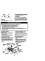
GENERAL OPERATION"
• Never carry p&_sengers.
, Do not mow in reverse unless absolutely necessary. Always look down and
behind before and while backing.
• Be aware of the mower discharge direction and do not point it at anyone. Do
not operate the mower without either
the entire grass catcher or the guard in
place.
• Slow down before turning.
• Never leave a running machine unattended; Always turn off blades, set parking brake, stop engine, and remove
keys before dismounting.
• Read, understand, and follow all instructions in the manual and on the machine
before starting.
• Only allow responsible adults, who are
familiar with the instructions, to operate
the machine.
• Clear the area of objects such as rocks,
toys, wire, etc., which could be picked
up and thrown by the blade.
• .Be,,sW_ the__areais clear of other people
before mowing. Stop machine if anyone
enters the area.
2
Tumblrbladas
when not mowing.
Stop engine before removing grass
catcher or unclogging chute.
Mow only in daylight or good artifloial
• Do not try to stabilize the machine by
putting your foot on the ground.
• Do not use grass catcher on steep
slopes.
light.
CHILDREN
Do not operate the machine while under
the influence of alcohol or drugs.
Watch for traffic when operating near or
crossing roadways.
Use extra care when loading or unloading the machine into a trailer or truck.
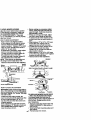
;LOPE OPERATION
;lopes are a major factor related to loss,f-control and tipover accidents, which
:an result in severe injury or death. All
lopes reqhim-eXtPa caution. If you cannot
up the slope or if you feel uneasy on
:,do not mow if.
)0:
Mow up and down slopes, not across.
Remove obstacles such as rocks, tree
limbs, etc.
Watch for holes, ruts, or bumps. Uneven
terrain could overturn the machine. Tall
grass can hide obstacles.
Use slow speed. Choose a low gear so
that you will not have to stop or shift
while on the slope.
Follow the manufacturer's recommendations for wheel weights or counterwel'ghts to improv_ .stal:)ilify.
Use extra care with grass catchers or
other attachments. These can change
the stability of the machine.
Keep all movement on the slopes slow
and gradual. Do not make sudden
changes in speed or direction.
"Avoid starting or stopping on a slope. If
tires lose traction, disengage the blades
and proceed slowly straight do'_'n the
slope.
,O NOT:
Do nottum on slopes unless necessary,
and then, tum slowly and gradually
downhill, if possible.
Do not mow near drop-offs, ditches, or
embankments. The mower could suddenly tum over if a wheel is over the
edge of a cliff or ditch, or if an edge
caves in.
Do not'i_IB_ on_l_et grass. Reduced
traction could cause sliding.
Tragic accidents can occur if the operator
is not alert to the presence of children.
Children are often attracted to the
machine and the mowing activity. Never
assume that children will remain where
you last saw them.
• Keep children out of the mowing area
• and under the watchful care of another
responsible adult.
• Be alert and tum machine off if children
enter the area.
• Before and when backing, look behind
and down for smell children.
• Never carry children. They may fag off
and be: seriously injured or interfere with
safe machine operation.
• Never allow children to operate the
machine.
• Use extra care when approaching blind
comers, shrubs, trees, or other objects
that may obscure vision.
SERVICE
• Use extra care in handling gasoline and
other fuels. They are flammable and
vapors are explosive.
- Use only an approved container.
- Never remove gas cap or add fuel
with the engine running. Allow engine to cool before refueling. Do not
smoke.
- Never refuel the machine indoors.
- Never store the machine or fuel
container inside where there is an
open flame, such as a water heater.
• Never run a machine inside a closed
area.
attachment bolts, tight and keep equip
mant in good condition.
Never tamper with safety devices.
Check their proper operation regularly.
Keep machine free of grass, leaves, or
other
build-up.
Clean oil or
fuel
Keep debris
nuts and
belts, especially
blade
spillage. Allow machine to cool before
stodng.
Stop and inspect the equipment if you
stdke an object. Repair, if necessary,
before restarting.
• Mower bladesare sharpand can cut.
Wrap the blade(s) or wear gloves,and
use extracaution when servicing them.
• Check brake operationfrequently.
Adjustand serviceas required.
Neyer make adjustmentsor repairswith
the engine running.
Grass catcher componentsare subject
to wear, damage, and deterioration,
whichcould expose movingparts or
allowobjectsto be thrown.Frequently
checkcomponents and replacewith
manufacturer'srecommendedparts,
when necessary.
• Be sure the area is clear of otherpeople
before mowing.Stop machineif anyone
enters the area.
• Never carry passengers.
• Do not mow in reverseunlessabsolutely necessary.Always lookdownand
behindbefore and while backing.
• Never carry children.They may fall off
and be seriously injuredor interferewith
safe machineoperation.
• Keep childrenout of the mowingarea
and under the watchfulcare of another
responsibleadult.
• Be alert and tum machineoffif children
_enter the area
• Before and when backing,lookbehind
and downfor smallchildren.
• Mow up and downslopes(15° Max), not
across.
• Remove obstaclessuch as rocks,tree
limbs,etc.
• Watch for holes, ruts,or bumps.Uneven
terrain could overtumthe machine. Tall
grass can hide obstacles.
• Use slow speed.Choose a low gear so
that you willnot have to stop or shift
while on the slope.
• Avoidstartingor stoppingon a slope. If
tires lose traction,disengagethe blades
and proceedslowlystraightdownthe
slope.
• Do nottum on slopesunlessnecessary,
and then, turnslowlyand gradually
downhill,if possible.
_Look
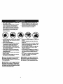
for this symbol to point out important safety precautions. It means CAUTION!!! BECOME AWAREI!I YOUR SAFETY IS INVOLVED.
_WARNING: The engine exhaustfrom
this productcontainschemicalsknownto
the State of Califomiato cause cancer,
birthdefects,oro.. otherreproductiveharm.
_CAUTION:
In order to prevent accidental starting when setting up, transporting,
adjusting or making repairs always disconnect spark plug wire and place wire where
it cannot contact spark plug.
4
PRODUCT
SPECIFICATIONS
GASOUNE
1.25GALLONS
CAPACITY
UNLEADED
AND'PiPE:
REGULAR
)ILTYPE
SAE30
_,PI-SF/SG/SH):
MAINTENANCE AGREEMENT
A Seam MaintenanceAgreementis available on this product.Contactyour nearest
Sears store for details.
CUSTOMER
(above 32°F)
SAE 5W-30
(below 32°F)
OIL CAPACITY:
3.0 PINTS
SPARK PLUG:
Champion RC12YC
SAP:.030")
VALVE
CLEARANCE:
INTAKE:
.003"-.005"
EXHAUST: .005"-.007"
GROUND SPEED
MPH):
. FORWARD: 0 - 5.7
REVERSE: 0- 2.7
TIRE PRESSURE:
FRONT: 14 PSI
REAR: 12 PSI
CHARGING
SYSTEM:
3 AMPS BA'n'ERY
5 AMPS HEADLIGHTS
BATTERY:
AMP/HR: 25
MIN. CCA:190
CASE SIZE: UIR
BLADE BOLT
TORQUE:
27-35 FT. LBS.
RESPONSlBILmES
• Read and observe the safety rules.
• Follow a regular schedule in maintaining, caring for and using your tractor.
• Follow the instructions under "Maintenance" and •'Storage" sections of this
owner's manual.
,_,WARNING: This tractor is equipped
with an internal combustion engine and
should not be used on or near any unimproved forest-covered, brush-covered or
grass-covered land unless the engine's
exhaust system is equipped with a spark
attester meeting applicable local or state
laws (if any). if a spark arrester is used, it
should be maintained in effective working
order by the operator.
In the state of California the above is
required by law (Section 4442 of the
California Public Resources Code). Other
states may have similar laws. Federal
laws apply on federal lands. A spark
attester for the muffler is available through
your nearest Sears Authorized Service
Center (See REPAIR PARTS section of
this manual).
CONGRATULATIONS
on your purchase
of a Craftsman Tractor. It has been
designed, engineered and manufactured
to clive you the best possible dependability
and performance.- _
Should you experience any problem you
cannot easily remedy, please contact your
nearest Sears Authorized Service Center.
We have competent, well-trained technicians and the proper tools to service or
repair this tractor.
"Please fead and retain tllis manual. The
instructions will enable you to assemble
and maintain your tractor prope'rly. Always
observe the "SAFETY RULES".
5
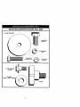
---_ -PARTS
BAG CONTENTS
SHOWN
FULL SIZE
(1) Large Flat Washer
(1) Hex Bolt
3/8-16 x I
O
(1) Lockwasher
3/8
(1) Hex Bolt
5/16-18x 1-1/4
@
(1) Locknut
5/16-18
(1) Shoulder Bolt
5/16-18-
(I) Knob
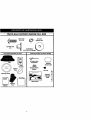
- - P-ARTS BAG CONTENTS
(2) Weld Nuts
#10
I_
SHOWN
FULL SIZE
(2) Screws
_
(2) Lock
#10 x 5/8
_
Washers#10
-tJ
I
3/16 (2)3/Wx
l_auge_
Parts packetseparatelyin carton
Parts Bag contentsnot shownfull size
(2) .LatchHook
Assemblies
Seat
Video
Cassette
Steer=ng
._
Steedng Wheel
Adapter
Mulcher
Wheel Insert
<:_
(2) Keys
Plate_
Steermg Wheel
Steedng ='
Extendon
Shaft
,,
Parts Bag
St_o_tg
O
Slope Sheet
Manual
7
Your-new-tractor
hasbeenassembled
atthefactory
withexception
ofthosepartsleft
unassembled
forshipping
purposes.
Toensuresafe_nd proper operation of your tractor
all parts and hardware you assemble must be tightened securely. Use the correct tools
as necessary to insure proper tightness. Review the video cassette before you begin.
• Position steering wheel so cross bars
TOOLS REQUIRED FOR
are horizontal (left to fight) and slide
. ASSEMBLY
inside boot and onto adapter.
A socketwrenchset willmake assembly
• Assemble large flat washer, 3/8 lock
easier.Standardwrenchsizes you need
washer, 3/8 hex bolt and tighten securely.
are listed below.
• Snap steering wheel insert into center
(1) 3/4" Socket w/
(1) 9/16" wronch
of steering wheel.
ddve rachet
• Remove protective materials from trac(1) 3/4" wrench
tor hood and grill.
(1) Phillips Screw(2) 1/2" wrench
IMPORTANT:
Check for and remove any
driver
(1) Utility knife
staples in skid that may puncture tires
(1) "tire pressure
(1)Pliers
where tractor is to roll off skid.
........
gauge
When right or left hand is mentioned in
. Inseam/8
Hex Bolt
this manual, it means, from your point of
view, when you are in the operating posio
._3/8
Lockwasher
tion (seated behind the steedng wheel).
_Large
Rat
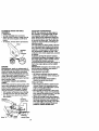
TO REMOVE TRACTOR
FROM
CARTON
UNPACK CARTON
• Remove all accessible loose parts and
parts boxes from shipping carton (See
page 6).
• Cut, from top to bottom, along lines on
all four comers of shipping carton, and
lay panels flak
--.-Check for any additional loose parts or
boxes and remove.
BEFORE
SKID
ATTACH
ROLLING
TRACTOR
STEERING
WHEEL
5/16 Locknut.__//
OFF
LowerSteedng_
Shaft
;
S, "_._--.
-"'t'{ • "., ;
-,.."
"..% ,,'!
ASSEMBLE EXTENSION SHAFT AND
-- BOOT
_
• Slide extension shaft onto lower steering shaft. Align mounting l_les in extension and lower shafts and install 5/16
hex belt and Iocknut. "l]ghten securely.
IMPORTANT: "r_jhten bolt and nut securely to 18-22 ft. Ibs. torque.
• Place tabs of steering boot over tab
slots in dash and push down to secure.
TO ROLL TRACTOR OFF SKID (See
Operation section for location and
function of controls)
• Press lift lever plunger and raise attachment lift lever to its highest position.
• Release parking brake by depressing
clutch/Drake pedal.
• Place freewheel control in freewheeling
position to disengage transmission (See
"TO TRANSPORT" in the Operation
section of this manual).
• Roll tractor forward off skid.
• Remove banding holding discharge
guard up against tractor.
INSTALL STEERING WHEEL
• Position front wheels of the tractor so
they are pointing straight forward.
• -Slll_z_eel_ng wheel adapter onto steering shaft extension.
8
lOW TOSETUPYOURTRACTOR
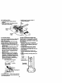
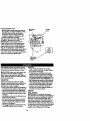
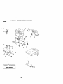
_'-HECK
BATTERY
Liftssss_t
_
to raised position and open
battery box door.
• If this battery is put into service after
month and year indicated on label (label
located between terminals) charge battery for minimum of one hour at 6-10
amps. (See "BA'I-I'ERY" in MAINTENANCE section of this manual for
charging instructions).
Seat
SeatPan
i
•
Shoulder
Bolt
L,r--_.,
Washer
Adjusl_nant Knob
Seat Pan
BatteryBox
Door
Terminal
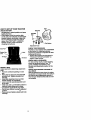
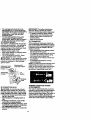
INSTALL SEAT
Adjustseat beforetighteningadjustment
knob.
• Remove cardboardpackingon seat
pan.
• Placeseat on seat pan and assemble
shoulderbolt.Tightenshoulderbolt
,_rely.
.....
• Assembleadjustmentknob and fiat:
washer loosely.Do nottighten.
• Lowerseat intooperatingpositionand
siton seat.
• Slide seat untila comfortablepositionis
reachedwhichallowsyou to press
clutch/brakepedalall the way down.
• Get off seat withoutmovingitsadjusted
position.
-"
• Raise seat and tighten adjustmentknob
securely.
CHECK TIRE PRESSURE
The tires on yourtractorwere ovednflated
at the factory for shippingpurposes.
Correcttire pressureisimportantfor best
cuttingperformance.
• Reducetire pressureto PSI shownin
=PRODUCT SPECIFICATIONS"on
page 5 of this manual.
CHECK DECK LEVELNESS
For best cuttingresults,mowerhousing
shouldbe properlyleveled.See "TO
LEVEL MOWER HOUSING" in the
Service and Adjustmentssectionof this
manual.
CHECK FOR PROPER POSITION OF
ALL BELTS
See the figures that are shown for replacing motion and mower blade drive belts in
the Service and Adjustments sectoin of.
this manual. Verify that the belts are routed correctly.
CHECK BRAKESYSTEM
6,fter you learn how to operate your trac:or, check to see that the brake is propedy
adjusted. See "TO ADJUST BRAKE" in
_heService and Adjustments section of
this manual.
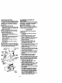
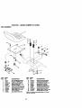
INSTALL MULCHER PLATE
• Install two latch hooks to mulcher plate
. using screw, washer, lock washer, and
weld nut as shown.
NOTE: Pre-assemble weld nut to latch
hook by inserting weld nut from the top
with hook pointing down.
, Tighten hardware securely.
• Raise and hold deflector shield in upright position.
• Place front of mulcher plate over front of
mower deck opening and slide into
place,-as shown. -• Hook front latch into hole on front of
mower deck.
• Hook rear latch into hole on back of
mower deck.
TO CONVERT TO BAGGING OR
DISCHARGING
Simply remove mulcher plate and storein
a safe place. Your mower is now ready for
discharging or installation of optional
grass catcher accessory.
NOTE: It is not necessary to change
blades. The mulcher blades are designed
for discharging and bagging also.
v' CHECKLIST
PLEASE REVIEW THE FOLLOWING
CHECKLIST:
v' All assembly instructions have been
completed.
v' No remaining loose parts in carton.
v" Battery is properly prepared and
charged. (Minimum I hour at 6 amps).
v' Seat is adjusted comfortably and
tightened securely.
v' All tires are properly inflated. (For
shipping purposes, the tires were
overinflated at the factory).
v' Be sure mower deck is properly leveled
side-to-side/front-to-rear for best
cutting results. (Tires must be properly
inflated for leveling).
v' Check mower and drive belts. Be sure
they are routed properly around pulleys
and inside all belt keepers.
v' Check wiring. See that all connections
are still secure and wires are propedy
_,CAUTION:
Do not remove discharge
guard from mower. Raise and hold guard
when attaching mulcher plate and allow it
to rest on plate while in operation.
Weld
Weld Nut From
Hook Points
The Top
Down
Lock
Washer
damped.
Latch
Latch
WHILE LEARNING HOW TO USE YOUR
TRACTOR, PAYEXTRAATTENTION TO
THE FOLLOWING IMPORTANT ITEMS:
Weld Nut
LockWasher
Washer
Mulcher
Rate
Deflecto¢
Shield
v' Before driving tractor, be sure freewheel control is in drive position.
/ Engineoil is atproper level.
,/ Fueltank is filledwithfresh, clean,
regularunleadedgasoline.
/ Becomefamiliarwithall controls- their
locationand function.Operate them
before you startthe engine.
,/ Be sure brake system is in safe operatingconditi_.
,/ It is importantto purgethe _issionbeforeoperatingyourtractorfor
. the firsttime. Followproperstarting
_,an,_r_ion purginginstructions
(See "TO START ENGINE" and
"PURGE TRANSMISSION" in the C)perationsectionof this manual).
_Washer
"_._.Screw
Latch
Hooks
10
"hesesymbolsmay appearon yourtractororin literaturesuppliedwiththe product.
.eam and understandtheirmeaning.
BAI'rlERY
CAUTION OR
WARNING
REVERSE
ENGINE ON
ENGINE OFF
OIL PRESSURE
FORWARD
CHOKE
®
MOWER HEIGHT
PARKING BRAKE
LOCKED
H L
ATTACHMENT
CLUTCH ENGAGED
IGNITION
D_V_E_,
KEEP
_
REVERSE
NEUTRAL
ATTACHMENT
CLUTCH DISENGAGED
SLOW
UGHTS ON
!'.,i
FUEL
FAST
HIGH
LOW
KEEP AREA CLEAR
UNLOCKED
MOWER UFT
(®>_I
PARKING BRAKE
SLOPE HAZARDS
(SEE SAFETY RULES SECTION)
FREEWHEEL
_O FEET
AWAY
11
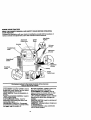
KNOWYOURTRACTOR
READTHISOWNER'S
MANUALAND
SAFETY
RULES
BEFORE
OPERATING
YOUR-TRACTOR
Compare
theillustrations
withyourtractor
tofamiliadze
yourself
withthe locations of
various controls and adjustments. Save this manual for future reference.
Attachment
Clutch Lever
Ignition
Switch
Ught Switch
Position
Ammeter
Uft Lever
Throttle/Choke
Pedal
Attachment
Uft Lever
I
Clutch/Brake
Contro;
Height
Adjustment
Indicator
Freewheel
Control
Parking
Motion
Control Lever
Our tractorsconformto the safetystandardsof theAmerican
NationalStandardsInstitute.
ATTACHMENT CLUI:CH LEVER: Used to
engage the mower blades, e_other attachments mounted to your tractor.
MGHT SWITCH: Turns the headlights on
and off.
THROI"rLE/CHOKE
CONTROL: Used to
control engine speed.
CLUTCH/BRAKE PEDAL: Used for
declutching and braking the tractor and
starting the engine.
FREEWHEEL CONTROL: Disengages
transmission for_)ushing or slowly towing
t.hetL_W_orw._h the engine off.
MOTION CONTROL LEVER: Selects the
speed and direction of the tractor.
ATTACHMENT LIFT LEVER: Used to
raise and lower the mower deck or other
attachments mounted to your tractor.
LIFT LEVER PLUNGER: Used to release
attachment lift lever when changing its
position.
IGNITION SWITCH: Used for starting and
stopping the engine,
AMMETER: Indicates battery charging (+)
or discharging (-).
PARKING BRAKE: Locks clutch/brake
into the brake position.
12
The operationof anytractorcan resultin foreignobjectsthrownintothe
l
eyes, whichcan resultin severe eye damage.Alwayswear safetyglasses
or eye shieldswhile operatingyourtractoror performing any adjustmentsor
rL_pairs.
We recommenda wide visionsafety mask over spectacles,or standardsafety glasses.
I
HOW TO USE YOUR TRACTOR
Yourtractoris equippedwith an oporator
presencesensingswitch.When engine is
r0nning,any attempt bythe operatorto
leave the seat withoutfirstsettingthe
parkingbrake willshut offthe engine.
TO SET PARKING BRAKE
• Depressclutch/brakepedal intofull
"BRAKE" positionand hold.
Placeparkingbrake leverin "ENGAGED"position,and releasepressure
from clutch/brakepedal. Pedal should
remainin "BRAKE" position.Make sure
parkingbrakewill holdtractorsecure.
• Tumignr_ion
keyto"OFF"position
and
rernovekey.Always_
keywhen
leavingtractortopreventunauthorized
use.
• Never use choketo stopengine.
IMPORTANT:Leavingthe ignitionswitch
in any positionotherthan "OFF' will cause
the batteryto be discharged(dead).
NOTE: Undercertainconditionswhen
tractoris standingidle withthe engine running,hot engineexhaustgases may
cause "browning" ofgrass.To eliminate
this possibility, alwaysstopenginewhen
stoppingtractoron grass areas.
•,CAUTION: AlwaysstoptractorcomThrottle/Choke
Attachment Clutch
Lever=Engaged" pletely,as describedabove,beforeleaving
Control
Position
the operator'sposition,to emptygrass
"Disengaged" catcher,etc.
I Position
THROTTLE CONTROL
Alwaysoperateengine at full throttle.
"Brake"
• Operatingengine at lessthan full throtPosition
tle reducesthe batterychargingrate.
• Full throttle offersthe bestbaggingand
mower performance.
TO MOVE FORWARD AND BACKWARD
The directionand speed of movementis
controlledby the motioncontrollever.
Motion
Clutch/Brake
*Disengaged"
Control
• Start tractorwith motioncontrollever in
PedaL*Drive"
Position
Lever
neutral (N) position.
Position_
• Release parkingbrake and clutch/brake
STOPPING
p_lal.
MOWER BLADES
• Slowlymove motioncontrollever to
desired position.
• To stop mower blades, move attachment clutch Lever to "DISENGAGED"
NOTE: The effortto movethe motioncontrol leverwill reduceafterthefirst few
position.
hoursof use. This;S normal.
_ROUND DRIVE
_'
TO ADJUST MOWER CUTTING HEIGHT
• To stop ground drive, depres_,,.
The positionof the attachmentliftlever
clutch/brake pedal into full "BRAKE" po.
determinesthe cuttingheight.
sition.
• Grasp lilt lever.
• Move motion control lever to neutral (N)
• Pressplungerwith thumband move
position.
leverto desiredposition.
IMPORTANT: The motion control lever
The cuttingheightrangeis approximately
does not retum to neutral (N) position
1-1/2 to 4". The heightsare measured
when the clutcl'Ubrake pedal is depressed.
from
the groundtothe bladetipwiththe
ENGINE
engine not running.These heightsare
• Move throttle control to slow position.
approximateand may very depending
NOTE: Failure to move throttle control to
uponsoilconditions, heightofgrass and
slow p_
an_-allowing engine to idle
typesof grass beingmowed.
before stopping may cause engine to
"backfire".
13
• The average lawn should be cut to
approximately 2-1/2 inches dudng the
cool season and to over 3 inches during
hot:months. For healthier and better
looking lawns, mow often and after
moderate growth.
• For best cutting performance, grass
over 6 inches in height should be
mowed twice. Make the first cut relative. ly high; the second to desired height.
TO OPERATE MOWER
Your tractor is equipped with an operator
presence sensing switch. Any attempt by
the operator to leave the seat with the
engine running and the attachment clutch
engaged will shut off the engine.
• Select desired height of cut.
• Start mower blades by engaging attachment clutch control.
• TO STOP-MOWER BLADES - disen,_age attachment clutch control.
CAUTION: Do not operate the mower
without either the entire grass catcher, on
mowers so equipped, or the discharge
guard in place.
AttachmentClutch
Position_
Lever'Engaged'
"Disengaged'_/"
IMPORTANT: The motion control lever
does not return to neutral (N) position
when the clutch/brake pedal is depressed.
• To restart movement, slowly release
parking brake and dutch/brake pedal.
• Slowly move motion control lever to
slowest setting.
• Make all rums slowly.
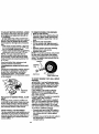
TO TRANSPORT
When pushing or towing your tractor, be
sure to disengage transmission by placing
freewheel control in freewheeling position.
Freewheel control is located at the rear
drawbar of tractor.
• Raise attachment lift to highest position
with attachment lift control.
• Pull freewheel control knob out and hold
in position by inserting retainer spring
into forward hole of control rod.
• Do not push or tow tractor at more than
two (2) aPR.
• To reengage transmission, reverse
above procedure.
NOTE: To protect hood from damage when
transporting your tractor on a truck or a
trailer, be sure hood is dosed and secured
to tractor. Use an appropriate means of
tying hood to tractor (rope, cord, etc.).
AttachmentLilt
LeverHigh Position
/
ll_ _
LOW
P on
TOWING CARTSAND OTHER
A'I'rACHMENTS
Towonlythe attachmentsthat are recommended by and complywith specif'_,ations
of the manufacturerofyour tractor.Use
commonsensewhen towing.Too heavyof
a load, while on a slope, is dangerous.
"nrescan lose traction with the ground and
cause you to lose control of your tractor.
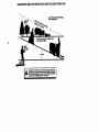
_TOOPERATE ON HILLS
ACAUTION:
Do not ddve up or down
hills with slopes greater than 1'_ and do
not drive across any slope. Use the slope
guide provided at the beck of this manual.
• Choose the slowest speed before starting up or down hills.
• Avoid stopping or changing speed on
hills.
• If slow isnecessary,
movethro.Je
control lever to slower position.
• If stopping is absolutely necessary, push
clutch/brake pedal quickly to brake positio.nad_bengageparking brake.
• Move motion control lever to neural (N)
position.
14
BEFORE STARTING THE ENGINE
3HECK ENGINE OIL LEVEL
, The _enginein yourtractorhas been
shipped,fromthe factory,alreadyfilled
with summerweight o,.
, Check engine oilwith tractoron level
_round.
emoveoil fillcap/dipstickand wipe
clean, reinsertthe dipstickand screw
cap tight,wait for a few seconds,
removeand read oil level. If necessary,
add oil until"FULL"mark on dipstickis
reached.Do not overfill.
Forcoldweather operationyou should
change oilfor easier starting(See "OIL
VISCOSITY CHART" in the Maintenance sectionofthis manual).
To change engineoil, see the Maintenance sectionin this manual.
_,DD GASOLINE
RII fuel tank. Use fresh, clean, regular
unleadedgasolinewith a minimumof 87
octane.(Use of leaded gasolinewill
increasecarbon and lead oxide
depositsand reducevalve life). Do not
mixoil withgasoline.Purchasefuel in
_uantities that can be used within30
ays to assure fuel freshness.
MPORTANT: When operatingin temperaures below32°F(0°C), use fresh, clean
vintergrade gasolineto help insuregood
•old weatherstarting.
_WARNING: Experienceindicatesthat
dcoholblendedfuels (calledgasoholor
=singethanolor methanol)can attract
nois_re whichlead_;.toseparationand
ormationof acidsduringstorage.Acidic
las can damage the fuel system of an
:nginewhile in storage.To avoidengine
)roblems,the fuel systemshouldbe emped beforestorage of 30 days or longer.
)rainthe gas tank, startthe engine and let
Tun untilthe fuel linesandcarburetor are
mpty. Use fresh fuel next season. See
;torageInstructionsfor additiona'rinforma'on. Never use engine or carburetor
:leanerproductsin the fuel tank or perma=entdamage may occur.
_CAUTION: Fill to bottomof gas tank
Ilerneck. Do not overfill.Wipe offany
pilledoil or fuel. DOnot store; spill or use
iasoline near an open flame.
O START ENGINE
Vhenstartingthe engine for the first time
r if the..e;)_q"e -;has
run.out of fuel, it will
lke extracrankingtimeto movefuel from
le tank to the engine.
15
• Be sure freewheelcontroliS.in the
transmissionengaged position.
• saonsset. opsra_ poal_ dsp_=
du=h',xa_ps_ and_ palm t_
• Place motion controllever in neutral (N)
position.
• Move attachmentdutch to "DISENGAGED"position.
• Move throttlecontrolto choke position.
NOTE: Beforestarting,read the warm and
coldstartingproceduresbelow.
• Insertkey intoignition and turn key
clockwiseto "START"positionand
release key as soonas enginestarts.
Do not runstarter continuouslyfor more
than f'dteensedondsper minute.If the
engine does not startafter several
attempts,movethrottle controlto fast
position,wait a few minutesand try
again. If engine stilldoes not start,
move the throttle controlback to the
choke positionand retry.
WARM WEATHER STARTING (,50_ F and
above)
• When enginestarts, move the throttle
controlto the fast position.
• The attachmentsand groundddve can
nowbe used. If the engine does not
acceptthe load, restartthe engineand
allowit towarm up for one minute using
the choke as describedabove.
COLD WEATHER STARTING ( 50° F and
below)
When enginestarts, allowengine to run
with the throttlecontrolin the choke
positionuntilthe engine runsroughly,
then movethrottle control to fast position. This may requirean engine warmup pedod fromseveral secondsto several minutes,dependingon the temperature.
AUTOMATIC TRANSMISSION WARM UP
• Beforedrivingthe unitin coldweather,
the transmissionshouldbe warmed up
as follows:
sure
the
tractoris
on level (jround.
•" Be
Place
the
motion
controllever
,n neutral.
Release the parkingbrake and let the
clutch/brakeslowlyreturnto operating
position.
• Allowone minutefor transmissionto
warm up.This can be done dudngthe
enginewarm up period.
• The attachmentscan also be used duringthe enginewarm-upperiod afterthe
transmissionhas been warmedup.
NOTE:
At a high altitude (above 3000
feet) or in cold temperatures (below 32 F)
the carburetor fuel mixture may need to be
adjusted for_best engine performance.
See "TO ADJUST CARBURETOR" in the
Service and Adjustments section of this
manual.
PURGE TRANSMISSION
,_CAUTION:
Never engage or disengage freewheel lever while the engine is
running.
To ensure proper operation and performance, it is recommended that the transmission be purged before operating tractor
for the first time. This procedure will
remove any trapped air inside the transmission which may have developed during
shipping of your tractor.
IMPORTANT: Should your transmission
require removal for service or replacement, it should be purged after reinstallation before operating the tractor.
• Place tractor safely on level surface with
engine off and parking brake set.
• Disengage transmission by placing freewheel control in freewheeling position
(See "TO TRANSPORT" in this section
of manual).
• Sitting in the tractor seat, start engine.
After the engine is running, move throttle control to slow position. With motion
control lever in neutral (N) position,
slowly disengage clutch/brake pedal.
• Move motion control lever to full forward
position and hold for five (5) seconds.
Move lever to full reverse position and
hold for five (5) seconds. Repeat this
procedure three (3) times.
NOTE: During this procedure there will be
no movement of drive wheels. The air is
• Slowly move motion control lever forward; after the tractor moves approximately five (5) feet, slowly move motion
control lever to reverse position. After
the tractor moves approximately five (5)
feet retum the motion control lever to
the neutral (N) position. Repeat this procedure with the motion control lever
three (3) times.
• Your tractor is now purged and ready for
normal operation.
MOWING TIPS
• Tire chains cannot be used when the
mower housingis attached to tractor.
• Mower shouldbe properly leveled for
best mowing performance. See =TO
LEVEL MOWER HOUSING" in the
Service and Adjustm.ents section of this
manual.
• The left hand side of mower should be
used for trimming.
• Drivesoth_
are_
onto
the area thathas been cULHave lhe cutarea
to the dghtd the baclor.This willresultin a
more evendislrbul_ oi cippir_ and mue
uniformcuta_
• When mowing large areas, start by turning to the right so that clippings will discharge away from shrubs, fences, driveways, etc. After one or two rounds, mow
in the opposite direction making left
hand tums until finished.
• If grass is extremely tall, it should be
mowed twice to reduce load and possible fire hazard from dried clippings.
Make first cut relatively high; the second
to the desired height.
• Do not mew grass when it is wet. Wet
grass will plug mower and leave undesirable clumps. Allow grass to dry
before mowing.
• Always operate engine at full throttle
when mowing to assure better mowing
performance and proper discharge of
material. Regulate ground speed by selecting a low enough gear to give the
mower the best cutting performance as
well as the quality of cut desired.
• When operating attachments, select a
ground speed that will suit the terrain
and give best performance of the attachment being used.
..being removed from hyd_mulicdrive system.
• Move motion control lever tjp,,.neutral(N)
position. Shut off engine and set parking
brake.
• Engage transmission by placing freewheel control in driving position (See
"TO TRANSPORT" in this section of
manual).
• Sitting in the tractor seat, start engine.
After the engine is running, move throttle control to half (1/2) speed. With
motion control lever in neutral (N) posi-
JJ
tions_lowly d_engage clutch/brake
pedal =--16
AULCHING MOWING TIPS
MPORTAN'P...For bestperformance, keep
nowerhoo_ing free of built'up grass and
rash. Clean after each use..
The special mulching blade will recut
the grass clippings many times and.
reduce them in size so that as they fall
onto the lawn they will disperse into the
grass and not be noticed. Also, the
dlulched grass will biodegrade quickly
to provide nutrients for the lawn. Always
mulch with your highest engine (blade)
speed as this will provide the best recutting action of the blades,
Avoid cutting your lawn when it is wet.
Wet grass tends to form clumps and
interferes with the mulching action. The
best time to mow your lawn is the early
afternoqn. At_thj_S
time the grass has
dried and the newly cut area will not be
exposed to the direct sun.
For best results, adjust the mower cutting height so that the mower cuts off
only the top one-third of the grass
blades: For extremely heavy mulching,
reduce your width of cut on each pass
and mow slowly.
• Certain types of grass and grass conditions may require that an areabe
" mulched a second time to completely
hide the clippings. When doing a second cut, mow across or perpendicular to
the first cut path.
• Change your cutting pattem from week
to week. Mow north to south one week
then change to east to west the next
week. This will help prevent matting and
graining of the lawn.
17
•
• •
•
.
.
sc.E u E
AS YOU COMPLETE
c_.k Sr_, Opm_o,
T_epressure
V'
l/
Chack Operator Presence and
T In_1o_ s_m
R C_ck _= b_o_ Fu_,,
Mower
V_
I/
I/
I/
V',
Blades
V_
cA
Shs_
T
Lu_'k_on_
V t,
I/
I/
R
c_m Battery
andTewninals/Recharge
Check
Tr_,_=k_Coo_
I_
I_
I/'
Adjust Blade Belt(s) Tension
Adjust
Molion
Ks
Drive Belt(s) Ter-_n
Ch_k-Engine-oil
E
Clean Air Alter
N
G
Clean
IN
Replace
E
Clean
L_el
I K
I_
I/2
Air Screen
inspect
_2
Muffler/Spark
Oil Rlter
Engine
Arres_r
"
(tf equipped)
t_l.=
CooJing Fins
Replace
Spark
Replace
Air Filter Paper
Replace
Fuel Filter
_2
Plug
I_
CartTidge
1 .Changemoreoftmwhenop_underal_mvyload_lnhighamblentt_nl_mre,
2 oSe,rvk_ n_r. o_n w_m opem_g in dl_y or du_y condl_.
3. # equipped w_ oil S_tw,chenOeol ev_y SOhours.
GENERAL
s
i t_
I/p
Zurm- S-lfequlpp_wlthadJu_dab_wsWn.
6. Not requiredV equ_oed wire me_eMnce-lme
7 - _
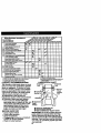
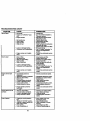
spark plug,clean or replaceair filter,and
check bladesand belts for wear.A new
spark plug and dean air fitterassure
properair-fuelmixtureand helpyour
engine runbetterand last longer.
BEFORE EACH USE
• Check engine oillevel.
• Check brake operation.
• Check tire pressure.
• Ch_.g_per-_or presenceand interlock
systemsfor properoperation.
• Check for loosefasteners.
hm
ax_
LUBRICATION
RECOMMENDATIONS
The warranty on this tractor does not cover
items that have been subjected to operator
abuse or negligence. To receive full value
from the warranty, operator must maintain
tractor as instructed in this manual. Some
adjustments will need to be made pedodicaily to properly maintain your tractor.
All adjustments in the Service and
--Adjustments section of this manual should
be checked at least once each season.
• Once a year you should replace the
[ t_
I_=
id_o_ belt ID _
IL-Im.
batmy._
nmalmum.
CHART
Zerk
Zerk
Wheel
Bearing
Zerk
Q FrontWheel
BearingZerk
Engine
_1
Clutch
O SAE 30 or 10w30 MotorOIL
• _Ge. r
Grease
@ Referto Maintenance"Engine"Section
IMPORTANT: Do not oil or grease the pivot
points which have special nylon bear-ings.
VLscous lubricants will attract dust and dirt
that will shorten the life of the seif-lubricating
bearings. If you feelthey must be lubricated,
use only a dry, powdered graphite type lubricant sparingly.
18
TRACTOR
Always observe safety rules when performing_any maintenance.
BRAKE-OPERATION
If tractor requires more than six (6) feet
stopping distance at high speed in highest
gear, then brake must be adjusted. (See
"TO ADJUST BRAKE" in the Service and
Adjustments section of this manual).
TIRES
• Maintain proper air pressure in all tires
(See "PRODUCT SPECIFICATIONS"
on page 3 of this manual).
• Keep tires free of gasoline, oil, or insect
control chemicals which can harm rubber.
• Avoid stumps, stones, deep ruts, sharp
objects and other hazards that may
cause tire damage.
NOTE: To seal tire punctures and prevent
flat tires due to slow leaks, tire sealant
may be purchased from your local parts
dealer. "tiresealant also prevents tire dry
rot and corrosion.
.
OPERATOR PRESENCE SYSTEM
Be sure that operator presence and interlock systems are working properly, if your
tractor does not function as described
below, repair the problem immediately.
• The engine should not start unless the
clutch/brake pedal is fully depressed
and attachment clutch control is in the
disengaged position.
• When the engine is running, any
attempt by the operator to leave the
seat without first setting the parking
brake should shut off the engine;
• When the engine is running and the
attachment clutch is engaged, any
attempt by the operator to leave the
seat should shut off the engine.
• The attachment clutch should never
operate unless the operator is in the
seat:
_
BLADE CARE
For best results mower blade_'1_ust be
kept sharp. Replace bent or damaged
blades.
BLADE REMOVAL
• Raise mower to highest position to allow
access to blades.
• Remove hex belt, lock washer and flat
washer securing blade.
• Install new or resharpened blade with
trailing edge up towards deck as shown.
IMPORTANT: To ensure proper assembly,
center hole in blade must align with star
on mamlmt assembly.
• Reassemble hex bolt, lock washer and
flat washer in exact order as shown.
• "lighten belt securely (27-3.5 R. Lbs.
torque).
IMPORTANT: Blade bolt is Grade 8 heat
treated.
Trailing
Lock
Center
Hole
Mandrel
Star
Washer'_!_ 7
Hex Bolt (Grade 8)*
*A Grade 8 heat treated bolt can be
identified by six lines on the belt head.
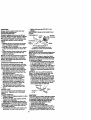
TO SHARPEN BLADE
NOTE: We de not recommend sharpening
blade, but if you do, be sure the blade is
balanced.
Care should be taken to keep the blade
balanced. An unbalanced blade will cause
excessive vibration and eventual damage
to mower and engine.
• The blade can be sharpened with a file
or on a grinding wheel. Do not attempt
to sharpen while it is on the mower.
• To check blade balance, you will need a
5/8" diameter steel bolt, pin, or a cone :
balancer. (When using a cone balancer;
follow the instructions supplied with balancer).
NOTE: Do not use a nail for balancing
blade. The lobes of the center hole may
appear to be centered, but are not.
• Slide blade onto an unthraaded portion
of the steel holt or pin and hold the bolt
or pin parallel with the ground. If blade
is balanced, it should remain in a horizontal position. If either end of the blade
moves downward, sharpen the heavy
end until the blade is balanced.
CenterHole
Blade
5/8" Bolt
or Pin •
BATrERY
Your tractor has a battery charging system
which is suff'_-'ientfor normal use. However, pedodic charging of the battery with an
automotive charger will extend its life.
• Keep battery and terminals clean.
• Keep battery bolts tight.
• Keep small vent holes open.
• Recharge at 6-10 amperes for I hour.
NOTE: The original equipment battery on
your tractor is maintenance free. Do not
attempt to open or remove caps or covers.
19
Adding
orchecking
levelofelectrolyte
is
NOTE: Althoughmulti-viscosity
oils
(5W30, 10W30 etc.) improvestartingin
notnecessary.
TOCLEAN
BATTERY
ANDTERMINALS coldweather,these multi-viscosity
oilswill
Corr_asion
anddirtonthebattery
andter- resultin increasedoilconsumption when
minals
car_
causethe battery to =leak"
used above 32°F. Checkyourengine oil
level more frequently to avoidpossible
enginedamage from runninglow on oil.
Change the oilafter every25 hoursof
operationor at least once a year if the
tractoris not used for 25 hoursin one
_ear.
heckthe crankcaseoil levelbeforestartingthe engineand after eacheight (8)
hoursof operation.Tightenoilfill cap/dipsticksecurelyeachtime youcheckthe oil
level.
TO CHANGE ENGINE OIL
Determinetemperaturerangeexpected
beforeoil change.Alloil mustmeet API
serviceclassificationSF, SG or SH.
• Be sure tractoris on level surface.
• Oil willdrain morefreely when warm.
• Catchoil in a suitablecontainer.
• Remove oilfillcap/dipstick.Be careful
notto allowdirtto enter the engine
when changingoil.
• Remove drainplug.
• After oil hasdrainedcompletely,replace
oildrain plugand tightensecurely.
• Refillenginewith oilthroughoilfill dipsticktube. Pourslowly.Do not overfill.
For approximatecapacitysee "PRODUCT SPECIFICATIONS=on page 5 of
this manual.
• Use gauge on oilfill cap/dipstickfor
checkinglevel.Be sure dipstickcap is
tightenedsecurelyfor accuratereading.
Keep oil at =FULL"lineon dipstick.
power.
• Open battery box door.
DisconnectBLACK battery cable first
then RED battery cable and remove
battery from tractor.
• Rinse the battery with plain water and
dry.
• Clean terminals and battery cable ends
with wire brush until bright.
• Coat terminals with grease or petroleum
jelly.
• Reinstall battery (See =REPLACING
BATTERY" in the SERVICE AND
ADJUSTMENTS section of this manu-
al.
V-B_LTS
Check V-beltsfor deterioration and wear
after 100 hours ofoperationand replaceif
necessary.:Thebeltsare notadjustable.
•Replacebelts if they beginto slipfrom
wear.
TRANSAXLE COOLING
The transmissionfan and coolingfins
shouldbe keptclean to assureproper
cooling.
Do notattemptto clean fan or transmissionwhile engineis runningor whilethe
transmissionis hot.
• Inspectcoolingfan to be surefan
bladesare intactand clean.
• Inspectcoolingfins for dirt,grass clippingsand othermaterials.To prevent
j:lamage to seals, do not use compressedair or high pressuresprayerto
clean coolingfins.
TRANSAXLE PUMP FLUID
The transaxlewas sealed at the factory
and fluidmaintenanceis not requiredfor
the lifeof the transaxle.Shouldthe
transaxleever leak or requireServicing,
--contact your nearest authorizedservice
center.
Oil Fill
_
Cap/Dipstick
Oil
ENGINE
LUBRICATION
Only usehigh qualitydetergentoil rated
withAPI serviceclassificationSF, SG or
SH, Selectthe oil'sSAE viscosity9rade
accordingto yourexpectedoperatingtemperature.
s
Dr_n
CLEAN AIR SCREEN
Air screen must be kept free of dirt and
chaff to prevent engine damage from overheating. Clean with a wire brush or compressed air to remove dirt and stubborn
dried gum fibers.
20
AIRFILTER
Yourengine
willnotrunproperly
usinga
dirtyairfilter.Cleanthefoampre-cleaner
aftere_e-ry
25hoursofoperation
orevery
season. Service paper cartridge every 100
hours of opemfionor every, season,
whichever occurs first.
Service air cleaner more often under dusty
conditions.
• "Remove knob(s) and cover.
TO.SERVICE PRE-CLEANER
.
• Slide foam pre-cleaner off cartridge.
• Wash it in liquid detergent and water.
• Squeeze it dry in a clean cloth.
• Saturate it in engine oil. Wrap it in clean,
absorbent cloth and squeeze to remove
excess oil.
• If very dirty or damaged, replace precleaner. .......
• Reinstall pre-cleaner over cartridge.
• Reinstall cover and secure with knob(s).
TO SERVICE CARTRIDGE
• Remove cartridge nut.
• Carefully remove cartridge to prevent
debris from entering carburetor. Clean
base carefully to prevent debris from
entedng carburetor.
• Clean cartridge by tapping gently on flat
surface. If very dirty or damaged,
replace cartridge.
• Reinstall cartridge, nut, precleaner,
cover and secure with knob(s).
IMP_ORTANT: Petroleum solvents, such as
kerosene, are not to-he used to clean the
cartridge. They may cause deterioration of
the cartridge. Do not oil cartridge. Do not
use pressurized air to clean or dry cartridge.
Cover
Knob _
_
ENGINE COOMNG RNS
Remove any dust, dirt or oil from engine
cooling fins to prevent engine damage
from overheating.
• Remove screws from blower housing
and lift housing and dipstick tube
assembly off engine.
• Cover oil fill opening to prevent entry of
dirL
• Use compressed air or stiff bristle brush
to thoroughly clean engine cooling fins.
• To reassemble, revemeabowe procedare.
Screws
air screen
DipstickTube
Assembly
Spark
Plug
EngineCooling
MUFFLER
Inspect and replace corroded muffler and
spark arrester (if equipped) as it could create a fire hazard an(gor damage.
SPARK
PLUGS
Replace spark plugs at the beginning of
each mowing season or after every 100
hours of operation, whichever occurs first.
Spark plug type and gap setting are
shown in =PRODUCT SPECIFICATIONS"
on page 5 of this manual.
Cartridge
IN-LINE
Pm-Q_an_"
BlowerHousing
,Scmws
FUEL FILTER
The fuel filter should be replaced once
each season, ff fuel filter becomes
dogged, obstructing fuel flow to carburetol;,replacement is required.
• With engine cool, remove filter and plug
fuel line sections.
• Place new fuel filter in position in fuel
line with arrow pointing towards carburetor.
• Be sure there are no fuel line leaks and
clam.ps are properly positioned.
I
21
Filter
CLEANING
• Clean engine, battery, seat, finish, etc.
" of all foreign matter.
• Keep finished surfaces and wheels free
of all gasoline, oil, etc.
• Protect painted sudaces with automotive type wax.
We do not recommend using a garden
hose to clean your tractor unless the electrical system, muffler, air filter and carburetor are covered to keep water out. Water
in engine can result in a shortened engine
life.
_,CAUTION:
Before performing any service or adjustments:
• Depress clutch/brake pedal fully and set parking brake.
• Place motion control lever in neutral (N) position.
• Place attachment clutch in "DISENGAGED" position.
•Tum ignition key "OFF" and remove key.
• Make-s_m the 15ladesand all moving parts have completely stopped.
• Disconnect spark plug wire from spark plug and place wire where it cannot come
in contact with plug.
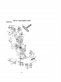
TO REMOVE MOWER
Mower will be easier to remove from the
right side of tractor.
• Place attachment clutch in "DISENGAGED" position.
• Move attachment lift lever forward to
lower mower to its lowest position.
• Roll belt off engine pulley.
• Disconnect clutch red from clutch lever
by removing retainer spring.
• Disconnect anti-swaybar from chassis
bracket by removing retainer spring.
• Disconnect suspension arms from rear
deck brackets by removing retainer
springs.
• Disconnect front links from deck by
removing retainer springs.
• Raise lift lever to raise suspension
arms. Slide mower out from under tractor.
IMPORTANT: If an attachment other than
the mower deck is to be mounted on the
tractor, remove the front links.
TO INSTALL MOWER
• Raise attachment lilt lever to its highest
position.
• Slide mower under tractor with discharge guard to right side of tractor.
• Lower lift lever to its lowest position.
• Install mower in reverse order of
removal instructions.
Retainer
suspe on
Spring
Arms
Front
Unk
Retainer Springs
(Both Sides)
Sp_ngs
(_othSides)
22
,'OLEVEL MOWER HOUSING
\djust the mower whiletractoris parked
,n level ground or driveway. Make sure
res are-prope-flyinflated(See "PRODICT SPECIFICATIONS'). If tires are
,ver or _Jndednflated,you willnot properly
_djustyour mower.
;IDE-TO-SIDEADJUSTMENT
Raise mowerto itshighestposition.
At the midpointof bothsides of mower,
measure heightfrom bottom edge of
mowerto ground. Distance",6,"on both
sides of mowershouldbe the same or
within 114"of each other.
If adjustmentis necessary,make adjustmenton one side of mower only.
To raise one side of mower,tightenlift
linkadjustmentnut on that side.
To lowerone side of mower,loosenlift
linkadjustmentnut on thatside.
|OTE: Eachfull turn of adjustmentnut
_illchange mowerheightabout 118".
Recheckmeasurementsafteradjusting.
Bottom
• Before making any necessary adjustments, check that both frontlinks are
equal in length. Both links should be
approximately 10-3/8".
• If links are not equal in length, adjust
one link to same length as other link.
• To lower front of mower loosen nut =E"
on both front links an equal number of
tums.
• When distance _ is 1/8" to 1/2" lower
at front than rear, tighten nuts'F"
against trunnion on both front links.
• To raise front of mower, loosen nut "F"
from trunnion on both front links.
"l]ghten nut "E" on both front links an
equal number of turns.
• When distance "[7" is 1/8" to 1/2" lower
at front than rear, tighten nut "F" against
trunnion on both front links.
• Recheck side-to-side adjustment.
ee
BothFrontUnks Shouldbe Equalin Length
• (_
Suspension
ift Unk Adjustment Nut
"RONT-TO-BACKADJUSTMENT
_tPORTANT: Deck mustbe level side-to;ide. If the followingfront-to-bdL'_ adjustnentis necessary,be sure to adjust both
font links equally so mower will stay
_velside-to-side.
b obtainthe bestcuttingresults,the
mowerhousingshouldbe adjustedso that
_e frontis approximately1/8"to 1/2"
)wer than the rear when the mower is in
:shighestposition.
;heckadjustmenton rightside oftractor.
4easuredistance=D"directlyin frontand
ehind_ndmt
at bottom edge of
lower hoL_sing
as shown.
Trunnion
ut"E"
FrontUnks
Trunnion
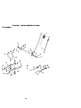
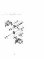
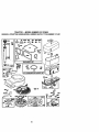
TO REPLACE MOWER BLADE DRIVE
BELT (See Illustration Next Page)
The mower bladedrivebelt may be
replacedwithouttools. Parkthe tractoron
level surface.Engage perking brake.
BELTREMOVAL
• Remove mowerfrom tractor(See "TO
REMOVE MOWER" in this sectionof
this manual).
• Work belt off both mandrel pulleysand
idlerpulleys.
23" Pullbelt away from mower.
3ELTINSTALLATION
• Install
newbeltinreverse
orderof
rem_ai._
• Makesurebeltisinallpulleygrooves
andinsideallbeltguides.
• Install mower in reverse order of
removal instructions.
Idler
Pulleys
Mandrel
Pulley
Mandrel
Pulley
TO ADJUST_BR_AKE
Your tractor is equipped with an adjustable
brake system which is mounted on the
side of the transaxle.
If tractor requires more than six (6) feet
stopping distance at high speed in highest gear, then brake must be adjusted.
• Depress clutch/brake pedal and engage
parking brake.
• Measure distance between brake operating arm and nut "A" on brake rod.
• If distance is other than 1-9116", loosen
jam nut and turn nut "A" until distance
becomes 1-9/16". Retighten jam nut
against nut"A'.
• Fload test tractor for proper stopping
distance as stated above. Readjust if
necessary. If stopping distance is still
greater than six (6) feet in highest gear,
further maintenance is necessary.
Contact your nearest authorized service center/department.
WithParkingBrake_'Engage@"
Jam Nut
,+ _l'l'l'l'l'l'l'l'l_
"
Do _ touchthisnut. If furtherbrakeadjustment
is necessarycontactyournearestauthorizedservice center/department
24
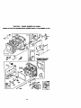
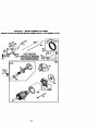
TO REPLACE MOTION DRIVE BELT
Park the tractor on level surface. Engage
parking brake. For assistance, there is a
belt installation guide decal on bottom side
of left footrest.
• Remove mower (See "TO REMOVE
MOWER" in this section of this manual.)
• Remove belt from stationary idler and
clutching idler.
• Pull belt slack toward rear of tractor.
Carefully remove belt upwards from
transmission input pulley and over cooling fan blades.
• Pull belt toward front of tractor and
remove downward from around engine
pulley.
• Install new belt by reversing above procedure.
Engine
Pulley
Clutching
Stationan
Transmission
Input Pulley
TOADJUST
MOTION
CONTROL
LEVER
Themotion
control
leverhasbeenpreset
atthefactoryand adjustment should not
TO REMOVE WHEEL FOR REPAIRS
• Block up axle securely.
• Remove axle cover, retaining ring and
washers to allow wheel removal (rear
wheel contains a square key -Do not
lose).
• Repair tire and reassemble.
• On rear wheels only: ar_jn grooves in
rear wheel hub and axle. Insert square
key.
• Replace washers and snap retaining
ring securely in axle groove.
• Replace axlecover.
NOTE: To seal tire punctures and prevent
flat tires due to slow leaks, tire sealant
may be purchased from your local parts
dealer. Tire sealant also prevents tire dry
rot and corrosion.
_e necessary_.
for any reason the motion control lever
will not hold its position while at-a selected
speed, it may be adjusted at the friction
oack located on the right side of transmission.
• Park tractor on level surface. Stop tractor by turning ignition key to "OFF" position, and engage parking brake.
• Adjust motion control lever by tightening
adjustment Iocknut one half (1/2) tum.
NOTE: If for any reason the effort to
move the motion control lever becomes
too excessive, reverse the above adjustment procedure by loosening Iocknut 1/4
to 1/2 tum.
Washers
Road test tractor after adjustment and
repeat procedure if necessary.
TRANSMISSION REMOVAUREPLACEMENT
Should your transmission require removal
for service or replacement, it should be
purged after reinstallation and before
operating the tractor. See "PURGE
TRANSMISSION" in the Operation section
of this manual.
Retaining
Ring
__
Axle Cover
_
Square Key
(Rear Wheel Only)
TO START ENGINE THAT HAS A WEAK
BATTERY
Adjustment
Locknut
T'O ADJUST STEERINGWHEEL
ALIGNMENT
If steering wheel crossbars are'_ot hodzontal (left to right) when wheels are positioned straight forward, remove steedng
wheel and reassemble per instructions in
the Assembly section of this manual.
FRONT WHEEL TOE-IN/CAMBER
The front wheel toe-in and camber are not
adjustable on your tractor. If damage has
occurred to affect the front wheel toe-in or
camber,,_tact_¥our
nearest authodzed
servi_e center_
ACAUTION: _Lead-acid battedes generate explosive gases. Keep sparks, flame
and smoking matedals away from batteries. Always wear eye protection when
around battedes.
If your battery is too weak to start the
•engine, it should be recharged. (See
"BATTERY" in the MAINTENANCE section of this manual).
If "jumper cables"-ara used for emergency
starting, follow this procedure:
AIMPORTANT:
Your tractor Is equiped
with a 12 volt negative grounded system.
The other vehical must also be a 12 volt
negative grounded system. Do not use
your tractor battery to start other vehicals.
TO ATTACH JUMPER CABLES • Connect each.and of the RED cable to
the POSITIVE (+) terminal of each battery, taldng carenot to short against
chassis.
• Connect one end of the BLACK cable to
the NEGATIVE (-) terminal of fully
charged battery.
25
• Connect the other end of the BLACK
cable to good CHASSIS GROUND,
aw_ayfrom fuel tank and battery.
TO REMOVE CABLES, REVERSE
ORDER • BLACK cable first from chassis and
then from the fully charged battery.
• RED cable last from both battedes.
PositiveTerminal
NegativeTerminal
Seat
BatteryBox
Door
(Red) Cable
Battery
Positive Terminal
Negative Terminal
REPLACING
BATTERY
&CAUTION:
Do not short battery terminals by allowing a wrench or any other
object to contact both terminals at the
same time. Before connecting battery,
mm0ve metal bracelets, wdstwatch
bands,tings,etc. Positive terminal must be connected first
to prevent sparking from accidental
groundin_
• Lift seat pan to raised position and open
battery box door.
• Disconnect BLACK battery cable first
then RED battery c_ble and carefully
remove battery from tractor.
• Install new battery with ta_inals in
same position as old battery.
• First connect RED battery cable to positive (+) terminalwithhex boltand kops
(Black)
TO REPLACE HEADLIGHT BULB
• Raise hood.
• Pull bulb holder out of the hole in the
backside of the gdll.
• Replace bulb in holder and push bulb
holder securely back into the hole in the
backside of the gdll.
• Close hood.
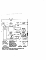
INTERLOCKS AND RELAYS
Loose or damaged widng may cause your
tractor to run poorly, stop running, or prevent it from starting.
• Check widng. See electdcal widng diagram in the Repair Parts section of this
manual.
TO REPLACE FUSE
Replace with 30 amp automotive-type
plug-in fuse. The fuse holder is located
behind the dash.
nut as shown."l'_htensecurely.
• Connect BLACK grounding cable to
negative (-) terminal with remaining hex
bolt and keps nut. Tighten securely.
• Close battery box door.
26
TOREMOVE
HOOD
ANDGRILL
ASSEMBLY
• Raise hood.
• Unsnap headlight wire connector.
• Stand in front of tractor. Grasp hood at
sides, tilt toward engine and lift off of
tractor.
• To replace, reverse above procedures.
Hood
\ _
Headlight
ENGINE
Manintanance,repair,or replacementof
the emissioncontroldevices and systems,
whichare being done at the customers
expense,may be performedby any nonroadengine repairestyablishmentor individual.Warrantyrepairsmustbe performedby an authorizedengine manufacturer'sserviceoutlet.
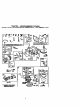
TO ADJUST THROI"rLE CONTROL
CABLE
The throttlecontr01-has
been preset at the
factory and adjustmentshouldnot be necessary,Check adjustmentas described
belowbeforelooseningcable. If adjustmentis necessary,proceedas follows:
• With engine not running,movethrottle
_ contro!lever from slowto chokeposition. Slowlymove leverfrom choke to
fast position.
_.,
Govemor
Governor
ControlLever
ControlPlate
Holes "A'
Clamp
Screw
ThrottleCable
27
TO ADJUST CARBURETOR
NOTE: The carburetor on this engine is
low emission. It is equipped with an idle
fuel adjusting needle with a limiter cap,
which allows some adjustment within the
limits allowed by the cap. Do not attempt
to remove the limiter cap. The limiter cap
cannot be removed without breaking the
adjusting needle.
The carburetor has been preset at the factory and adjustment should not be necessary. However, minor adjustment may be
required to compensate for differences in
fuel, temperature, altitude or load. If the
carburetor does need adjustment, proceed
as follows:
In general, tuming idle mixture valve in
(clockwise) decreases the supply of fuel to
the engine giving a leaner fuel/air mixture.
Tuming the idle mixture valve out
(counterclockwise) increases the supply of
fuel to the engine giving a richer fuel/air
mixture.
IMPORTANT: Damage to the needle valve
and the seat in carburetor may result if
screw is turned in too tight.
PRELIMINARY SETTING • Air cleaner assembly must be assembled to the carburetor when making carburetor adjustments.
• Be sure the throttle control cable is
adjusted propedy (see above).
FINAL SE'I-rlNG • Start engine and allow to warm for five
minutes. Make final adjustments with
engine running and shift/motion control
lever in neutral (N) position.
• Move throttle control lever to slow position. With finger, rotate and hold throttle
lever against idle speed screw. Turn idle
speed screw to attain 1750 RPM.
• While still holding throttle lever against
idle speed screw, turn idle mixture valve
full travel clockwise then counterclockwise until engine rune rough. Tum valve
to a point midway between those two
positions. Release throttle lever.
A,CCELERATION TESTMove throttle control lever from slow to
fast position. If engine hesitates or dies,
rum lille mixture valve out (counterclockwise) 1/8 turn. Repeat test and
continue to adjust, if necessary, until
engine accelerates smoothly.
High speed stop is factory adjusted. Do
not adjust--damage may result.
IMPORTANT: Never tamper with the
.=nginegovemor, which is factory set for
_roper engine speed, overspeeding the
engine above the factory high speed setling can be dangerous, if you think the
engine-governed high speed needs adjusting, contact your nearest authorized service center, which has proper equipment to
make any necessary adjustments.
Idle Speed
Screw
Throt'de
Lever
ValveWith
Umiter
Immediatelyprepareyourtractorforstorage at the end of theseason or if the tractor will not be used for 30 days or more.
ACAUTION: Never storethe tractorwith
gasolinein the tank insidea building
where fumes may reachan open flameor
spark.Allowthe engineto coolbefore storingin any enclosure:.
TRACTOR
Remove mowerfromtractorfor winter
storage:Thiswillallowyou to clean it thoroughly.Remove all dirt, grease,leaves,
etc. Store in a clean,dry area.
_- Cleartentiretractor(See "CLEANING"in
the Maintenancesectionof this manual).
• Inspectand replacebelts,if iT_'cessary
(See belt replacementinstructionsinthe
Service and Adjustmentssectionof this
manual).
• Lubricateas shownin the Maintenance
sectionofthis manual.
• Be sure that all nuts, boltsand screws
are securelyfastened.Inspectmoving
parts for damage, breakageand wear.
Replaceif necessary.
• Touchup all rustedor chippedpaint surfaced
liffhtlybefore painting.
28
BATTERY
• Fully charge the battery for storage.
• After a period of time in storage, battery
may require recharging.
• To help prevent corrosion and power
leakage during long periods of storage,
battery cables should be disconnected
and battery cleaned thoroughly (see "TO
CLEAN BATTERY AND TERMINALS" in
the Maintenance section of this manual).
• After cleaning, leave cables disconnected and place cables where they cannot
come in contact with battery terminals.
• If battery is removed from tractor for
storage, do not _ore battery directly on
concrete or damp surfaces.
ENGINE
FUEL SYSTEM
IMPORTANT: It is important to prevent
gum deposits from forming in essential fuel
system parts such as carburetor, fuel filter,
fuel hose, or tank during storage. Also,
experience indicates that alcohol blended
fuels (called gasohol or using ethanol or
methanol) can attract moisture which leads
to separation and formation of acids during
storage. Acidic gas can damage the fuel
system of an engine while in storage.
Drainthefueltank,
Starttheengine
andletitrununtilthe
OTHER
• Do not store gasoline from one season
fuel lines and carburetor are empty.
to another.
NeveLuse engine or carburetor cleaner
• Replace your gasoline can if it starts to
producLsin t-he fuel tank or permanent
rust. Rust and/or dirt in your gasoline will
damage may occur.
cause problems.
Use fresh fuel next season.
• If possible, store your tractor ind_rs
IOTE: Fuel stabilizer is an acceptable
and cover if to give protection from dust
Lltemative in minimizing the formation of
and dirt.
_el gum deposits during storage. Add sta• Cover your tractor with a suitable protec,ilizer to gasoline in fuel tank or storage
tive cover that does not retain moisture.
:ontainer. Always follow the mix ratio
Do not use plastic. Plastic cannot
ound on stabilizer container. Run engine
breathe, which allows condensation to
it least 10 minutes after adding stabilizer
form and cause your tractor to rust.
o allow the stabilizer to reach the carbureIMPORTANT: Never cover tractor while
or. Do not drain the gas tank and carbureengine and exhaust areas are still warm.
or if using fuel stabilizer.
"NGINE OIL
)rain oil (with engine warm) and replace
_ith clean engineoil. (See "ENGINE" in
he Maintenance section of this manual).
:YLINDER(S)
Remove spark plug(s).
Pour one ounce of oil through spark plug
hole(s) into cylinder(s).
Tum ignition key to "START" position for
a few seconds to distn'bute oil.
Replace with new spark plug(s).
29
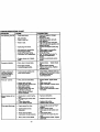
TROUBLESHOOTING
CHART
CAUSE
PROBLEM
Will not start
CORRECTION
• Outoffuel.
• Enginenot"CHOKED" prop-
e_
Engine flooded.
• Fill fuel tank.
• See "TO START ENGINE" in
Operation section.
• Wait several minutes before
attem_ngto start.
Bad sparkplug.
Dirtyair filter.
Dirtyfuelfilter.
Waterin fuel.
• Replace spark plug.
• Clean/replace air filter.
• Replace fuel filter.
• Drain fuel tank and cad)uretor,
refill tank with fresh
• Looseor damagedwidng.
• Carburetoroutof adjustmanL
• Engine valves out of adjustment.
Hard to start
•
Dirty aJrfilter.
• Weak or dead battery.
• Dirty fuel filter.
• Stele or dirty fuel.
• Clean/replace air filter.
• Replace spark plug.
• Recharge or replace battery.
• Replace fuel filter.
• Drain fuel tank and refill with
• Loose or damaged wiring.
• Carburetoroutof adjustment.
•
•
• Badsparkplug.
• Enginevalvesoutof adjustment.
Engine will not tum
over
gasoline and replace fuel filter.
• Check all widng.
• See "To Adjust Carburetor" in
Service and Adjustments
section.
• Contact an authorized service
center.
fresh gasoline.
Check all widng.
See "To Adjust Carburetor" In
Service and Adjustments
section.
• Contect an authorized service
center.
• Clutch/brakepedal not
depressed.
• Attachmentdutch is engaged.
• Weak or dead battery.
• Blownfuse.
• Corrodedbatteryterminals.
• Looseor damaged wiring.
• Faultyignitionswitch.
• Faultysolenoidor starter.
•
•
•
•
•
•
•
• _Faulty operatorpresence
•
Depress dutch/brake pedal.
switch(es).
Engine dicks but will
not start
•
•
•
•
Weak or dead battery.
Corroded battery terminals.
Loose or damaged widng.
Faulty solenoid or starter.
•
•
•
•
Lossofpower
• Cutting too much gress/too
fast.
• Throttle in "CHOKE" position.
• Build-up of grass, leaves and
trash under mower.
• Dirty air filter.
• LOWoil level/dirty oil.
•
30
Disengage attachment dutch.
Recharge or replace battery.
Replace fuse.
Clean battery terminals.
Check all widng.
Check/replace ignition switch.
Check/replace solenoid or
starter,
Contact an authorized service
canter,
Rechargeor replace battery.
Clean battery terminals.
Check all wiring.
Check/replace solenoidor
starter.
Set in "Higher Cut" position/reduce speed.
• Adjust throttle control.
• Clean underside of mower
housing.
• Clean/replace air filter.
• Check oil level/change oil.
CHART
TROUBLESHOOTING
PROBLEM
CAUSE
i LossoLppwer(cent'd)
i
CORRECTION
•
Faulty spark plug.
• Clean and regap or change
•
Dirty fuel filter.
Stale or dirty fuel.
• Replace fuel filter.
• Drain fuel tank and refill with
sparkplug.
• Water in fuel.
•
• Spark plugwire loose.
•
•
•
•
•
•
•
•
•
Dirty engine air screen/fine.
Dirty/clogged muffler.
Loose or damaged widng.
Carburetor out of adjustment.
fresh gasoline.
Drain fuel tank and carburetor,
refill tank with fresh gasoline and
replace fuel filter.
Connect and tighten spark plug
wire.
Clean engine air scmon/fins.
Clean/replace muffler.
Check all widng.
See "To Adjust Carburetor" in
Serv_eandAdjustments
•
Engine valves out of adjust-
ment.
Excessivevibration
• Worn, bent or loose Made.
•
•
Bent blade mandrel.
Loose/damaged pad(s),
section.
• Contact an authorized eervice
center.
•
Replace blade.
Tighten blade
boll
• Replace blade mandrel.
• Tighten iooea part(s). Replace
damagedparts.
Enginecontinuesto
run whenoperator
leaves seat with at
tachmentclutch
engaged
• Faultyoparator-safetypresence controlsystem.
• Check
wi_ng,sw_chee
andcon-
Poorcut- uneven
• Worn, bent or loose blade.
• Replace blade. Tighten blade
boll
• Level mower deck.
• Clean underside of mower hous-
• Mower deck not level.
• Buildup of grass, leaves, _nd
trash under mower.
• Bent blade mandrel.
• Clogged mower deck vent
holes from buildup of
grass, leaves, and trash
around mandrels.
Mower blades will not
rotate
Poor grass discharge
nections. If not corrected, contact
an authorized service
center/department.
ing.
• Replace blade mandrel.
• Clean around mandrels to open
vent .holes.
• _Obstruction in dutch mechanism.
• Worn/damaged mower ddve
belt. "• Frozen idler pulley.
• Frozen blade mandrel.
• Remove obstruction.
• Engine speed too slow.
•
• Travel speed toofesL
• Wet grass.
•
•
• Mower deck not level.
• Low/uneven tire air pressure.
• Worn, bent or looseblade.
31
• Replace mowerdrive bell
• Replaceidler pulley,
• Replaceblade mandrel.
Place throttle control in "FAST"
pomon.
Shift to slower speed.
Allow grass to d_J before mowing.
• Level mower deck.
• Check tires for proper air pressure.
• Replace/sharpen blade. Tighten
blade bolt.
TROUBLESHOOTING
CHART
PROBLEM
CAUSE
CORRECTION
Poor grass discharge
(con_)
--
• Buildup of grass, leaves and
trash under mower.
• Mower drive belt worn.
•
• Blades improperly installed.
•
Improper blades used.
Clogged mower deck vent
holes from buildup of
grass, leaves, and trash
around mandrels.
Clean underside of mower hou_
ing.
• Replace mower ddve belt.
• Reinstall blades sharp edge
down.
• Replace with blades listed in this
rnanual.
• Clean mound mandrels to open
vent holes.
Headlight(s) not
working (if so
equipped)
• Switch is "OFF'.
• Bulb(s) burned out.
• Faulty light switch.
• Loose or damaged wiring.
• Blown fuse.
•
•
•
•
•
Battery _M-_ot ....
• Bad battery cell(s).
• Poor cable connections.
• Faulty regulator (if so
• Replace battery.
• Check/clean all connections.
charge
i*
Turn switch "ON'.
Replace bulb(s).
Check/replace light switch.
Check wiring end corrections.
Replace fuse.
Replace regulator.
equipped).
Loss of drive
• Faulty alternator.
• Replace alternator.
•
• Place freewheel control in
Freewheel control in "disengaged" pos_on.
• Motion drive belt worn, dam-
"engaged" position.
• Replace motion drive belt.
agedor broken.
• Air trapped in transmission
during shipment
or servicing.
Engine "backfires"
when tumlng engine
"OFF"
Enginethrottle controlnotset
at'SLOW" positk)nfor 30
secondsbefore stopping
engine.
32
• Purgetransmission.
• Move throttle control to "SLOW"
pesltJonend allow to idle for 30
seconds before stopping engine.
TRACTOR - - MODEL NUMBER 917.270623
SCHEMATIC
BAI"rERY
FUSE 30 AMP.
;-_,
,©,
i
!
i _
I
STARTER
_-_1_ =
.......
t
I
I
0_----7
1
I
"_'.
"--_--'
(NOT OCCUPIED)
: SEAT SWITCH
_
._
_, __a_
'
: o_ou.o,_
v
b--_
(CLUTCH OFF)
(OPTIONAL)
eu_K
: _
I
_"
_E_..:
UNE I
I
I
q
J
CONNECTOR
SPARK
0
IGNITION
UNIT
........
GAP
PLUGSON
TWIN CYL ENGINES)
I
J
FUELSHUT-OFF.
_
_'"
I-
_
i u..n_o__ _
^ ^ ._
,,,;_-_T:
I .........
YOUR TRACTOR IS
EQUIPPED WITH A SPECIAL
ALTERNATOR SYSTEM.
THELIGHTSARENOT
CONNECTED
TOTHE
IGNITION SWITCH
PosmoN_
I _
I
r
I"+L
START IS.L+
-M_a_"
I
J
I
_
_
-T
j
_
V
T-
.I
_
I
BATTERY, BUT HAVE THEIR
_..
t_
_L--J
OWN ELECTRICAL SOURCE.
BECAUSE OF THIS, THE
HEADUGHTS
BRIGHTNESS OF THE LIGHTS
WIll"CHANGE WITH ENGINE
SPEED. AT IDLE THE LIGHTS
•
0
WILL DIM. AS THE ENGINE IS
NON-REMOVABLE
REMOVABLE
SPEEDED UP, THE LIGHTS
CONNECTIONS
CONNECTIONS
WILL BECOME THEIR BRIGHTEST.
WIRING INSULATED CUPS
NOTE: IF WIRING INSULATED CLIPS WERE REMOVED FOR
SERVICING OF UNIT, THEY SHOULD BE REPLACED TO
PROPERLY SECURE YOUR WIRING.
33
/_
TRACTOR - - MODEL NUMBER 917.270623
ELECTRICAL
_-
.÷__
22
-_
"-.
i
i
i
34
TRACTOR - - MODEL NUMBER 917.270623
ELECTRICAL
KEY
NO.
PART
NO.
DESCRIPTION
1
2
8
16
19
20
144925
74760412
156417
153664
STD551125
73350400
Battery 12 VOLT 25 AMP
Bolt Hex lid 1/4-20unc x 3/4
Case Battely
Switch, Inledock Push-In
WasherLock 1/4
Nut Jam Hex 1/4-20 Uric
21
22
24
25
26
147430
4152J
4799./
146147
108824X
Harness Asm Ught W/4152J
Bulb Light #1156
C,_eBattery6Ga
11"red
Cable Battery 6 Ga w116 wire red
Fuse 30 AMP Auto Green
27
28
73510400
4207J
Nut, Keps Hex 114-20 UNC
Cable Ground 6 Ga 12" black
29
30
31
32
33
40
41
42
43
121305X
140301
124211X
141226
109310X
156442
71110408
131563
145673
Switch Plunger Nc Gray
Switch Ign 4 Pos
Nut Ignition
CoverSwKeyBIk
1 25TextSLT
Key Ign Molded Craftsman
Harness Ign Man CI Am Hm 97
Bolt Blk. Fin Hex 1/4-20 Uric x I/2
Cover Terminal Red
Solenoid
44
45
52
70
73640400
121433X
141940
140422
Nut Keps BIk )-Iex 1/4-20 Unc
Ammeter Rectangular 6 Amp
Protection Wire Loop
Harness Engine B&S 14 OHV
NOTE: AIIcornponer4dimer,s_
1 inch= 25A mm
35
gkrenln U.S. ind'_
TRACTOR - - MODEL NUMBER 917.270623
CHASSIS AND ENCLOSURES
12
53
53
57
54
13
14
36
TRACTOR - - MODEL NUMBER 917.270623
CHASSIS AND ENCLOSURES
KEY
PART
NO.
NO.
DESCRIPTION
1
2
3
160393
140356
17490612
Chassis Assembly
Drawbar
Screw, Thd. Roll. 3/8-16 x 3/4
4
STD551025
Washer 13FJ2 x 3/4 x 16 Gauge
5
155272
Bumper_
6
8
9
155923
126471X
161938X013
Saddle
Cllp Insulator.406
Dash
10
11
12
13
14
15
16
17
18
24
STD533710
155927
145660
155934X010
17490608
74180512
STD541431
144983X558
126938X
STD523710
Bolt, Caldage 3/6.16 x 3/4
Panel, Dash, LH.
Clip l"mn,erman Gn'Ila P/L
Panel, Dash, R.H.
Screw Thdrol 3/8-16 x 1/2
Screw, Machine, Truss Head 5/16.18 UNC x 3/4
Nut
HoodAss_
Bumper Hood
Bolt
25
26
28
29
30
31
33
34
35
37
38
39
51
52
53
54
55
57
140
:14-5
--
19131312
STD541437
145198X558
155217X59g
157583X558
136619
145244X558
145243X558
STD533707
17490508
139886
139887
73800400
19091416
145201
161464
145202
STD522507
158418
156524
5479J
Washer 13/32 x 13/16 x 12 Gauge
Nut
Gn'lla w/Clips MS-558
Lens, Grille
Fender
Bracket, Fender
FooUest, LH.
Foolzest, R.H.
Boll
Scmw'l'hdrol 5/16-18 x 1/2
Pivot BracketAssemb_, LH.
Plvut Bracket Assembly, FLH.
Nut Lock w/Insert II4-20 UNC
Washer 9/32 x 7/8 x 16 Ga.
Bracket GlEe Pldtolf LH
Screw Hex Wshd #8-8 x 7/8
Bracket GlEe PIckolf RH
Bolt, Fin Flex 114-20 UNC x .75
Bracket Front Stmper¢_
....
Rod PivotQ'mssis,1-k)od
Plug, Button
Mtg Hole
emm
NOTE:AI componentdlmenslonsglven In U.S. inches
1 Irish = 26.4 mm
37
GROUND DRIVE
TRACTOR - - MODEL NUMBER 917.270623
38
TRACTOR - - MODEL NUMBER 917.270623
GROUND DRIVE
PART
NO.
1
2
3
8
10
16
140607
142431
144696
141003
76020416
73800500
18
19
74780616
7380O600
21
1 05933X
22
24
25
26
27
28
29
3O
32
34
35
36
37
38
39
40
41
42
47
48
5O
51
52
53
55
56
57
59
61
145627
733506O0
106888X
19131316
76020412
145204
12423OX
130807
74760512
155071
120183X
19211616
1572H
123674X
74760644
4470J
154777
19131312
127783
154407
123205X
74760624
7368O6OO
7368O5OO
105710X
165709X
74760620
141416
140312
17490612
62
53
64
65
66
8803R
140165
71170764
1O0407O0
154778
49
DESCRIPTION
KEY
NO.
Transmission, Asm.
Spdng, Retum, Brake
Pulk_y, Transmission
Rod, Shift
Pin, Cotter 1/8 x I
Nut, Lock Hex w/Ins 5/16-18
UNC
BoltHex3/8-16UNCx1Gr.5
Nut, Lock Hex w/Wsh 3/8-16
UNC
Knob P,d. 1/2-13 Plstc. TIxIs.
BIk.
Rod, Brake
Nut
S_odng,Rod, Broke
Washer 13/32 x 13/16 x 16 Ga.
Pin, Cotter 1/8 x 3/4
Rod, Parking Brake
Cap, Parking Brake
Bracket, Transmission
Bolt Flex 5/16-18 UNC x 3/4
Shaft, Foot Pedal
Bearing, Nylon
Washer
Pin, Roll
Pulley, Idler, Fiat
Bolt
Spacer, Split
Keeper, Bolt, Idler
Washer 13/32 x 13/16 x 12 Ga.
Pulley, Idler, V-Belt
Bellcmnk Clutch Grad Drusll
P,etalner, B_t
Bolt
Nut
NutCrownlock 5/16-28
Link, Clutch
Spdng, Return, Clutch
Bolt, Hex 3/8-16 UNC x 1-I/4
V-Belt, Drive
Keeper, Belt, Center
Screw,'rhdrol 3/6-16x3/4
Type "l-r
...
Cover, Pedal
Pu_.,
PART
NO.
69
70
71
72
73
74
75
76
77
78
81
62
83
64
65
87
88
89
93
94
95
96
97
98
100
103
142432
134683
141417
19132012
141418
121199X
121749X
12030001
123583X
121748X
156048
123782X
19171216
141423
157480
19212016
12000008
151147
142564
140462
144643
4497H
144201
73510600
19111216
73940800
104
105
105
108
141421
71070516
74780520
175410_6
109
116
145098
72110610
144
19111016
145
146
147
146
149
150
151
74490540
7449O536
74490524
159103
122052X
150935
19133210
DESCRIPTION
Screw
Guide, BeN, Mower Drive RH
Slxap, Torque, Lh
Washer 13/32 x !-114 x 12 Ga.
Suap,Torque,
Rh
Spacer,
Sl_
Washer 25/32 x 1-114 x 16 Ga.
Ring, E
Key,Square
Washer 25/32 x 1-5/8 x 16 Ga.
Asm, Shaft
Spdng, Tordon
Washer 17F-32x 3/4 x 16 Ga.
Rod, Tm
Bustdng
Washer 21/32 x 1-1/4 x 16 Ga.
R_O,Cl_
Console, Shltt
Une Fuel
Fan 7"
Cont_AsmBypass
Hydro
Spr_ Retainer
1"
Keeper, Belt Rh
NUt Keps 3/8-16 UNC
Washer 11/32 x 3/4 x 16 Ga.
NUt, Hex Jam Topkx'_ 1/2-20
UNF
Ann, Conlrol Pump ,500 Hydro
Bolt, Head Hex 5/18 x 18 x 1
Bolt H 5/16-18 UNC x 1-114
Screw Hex Wh Hd #10-24 x 15/8
Adaptor Fan I-lydro Lt Hyd Alum
Bolt Rdhd sq Neck 3/8-16 x 11/4
Washer 11/33 x 5/8 x 16
BOlt Hex Flghd 5/16-18 Gr. 5
Bo4tI-lex 5/16-18 x 2-1/4
Bolt I-lex 5/16-18 UNC x 1-1/2
spacer
.... SpacerRetainer
Bush_Ny_ Colemd
Washer 13/32 x 2 x 10
NOTE:_ compone_
d_emkm giveninU.S.inches
1 inch=25Amm
Bolt Hex 7/16 x 4 Gr. 5
Washer
Keeper,BeltEngineHydro
39
TRACTOR - - MODEL NUMBER 917.270623
STEERING ASSEMBLY
,.-..
• ,.
i
m ..-
:
.-
,
117
_.
_-_iL..
_'_
\\\
mr
_1,
I
15
_ "_
" ,
,
, ./,-,,,I,
o
, / _"_/_'/I / I
m
40
TRACTOR - - MODEL NUMBER 917.270623
STEERING ASSEMBLY
KEY
NO.
1
2
3
4
5
6
7
8
9
10
11
13
15
17
18
19
20
22
23
25
26
27
28
29
30
32
36
37
38
39
40
41
42
43
44
46
47
51
• 54
62
63
65
68
67
68
PART
NO.
139768
154427
156483
157473
6266H
121748X
19272016
12000029
3366R
156438
STD551137
154779
73901000
156546
57079
124035X
126684X
71200410
127501
154406
126847X
136874
19131416
17490612
STD561210
130465
155099
152927
139769
19133808
STD541537
100711L
145054
121749X
156720
121232X
6855M
STD541431
STD523112
156594
74780616
_'_1.780
154404
74781044
154429
DESCRIPTION
Steering Wheel
Front Axle Aseembly
Spindle Assembly, L.H.
Spindle Assembly, R.H.
Bearing, Race, Thrust, Hardened
Washer 25/32 x 1-5/8 x 16 Gauge
Washer 27/32 x 1-1/4 x 16 Gauge
Ring, Kiip
Beadng, Steering Column
Link, Drag
Washer, Lock
Spacer, Beadng, Front.axle
Nut, Lock, Flenge5/8-11 UNC
Shaft Assembly, Steedng
Washer, Thrust .515 x .750 x .033
Support, Shaft
Washer, Shim 1/4 x 5/8 x .062
Screw Hex Socket 1/4-20 x 5/8
Pittman Shaft Assembly
Bracket, Steering
Bushing, Unk' Drag
Gear, Sector
Washer 13/32 x 7/8 x 16 Gauge
Screw, Thd., Roll. 3/8-16 x 3/4
Pin
Rod, Tm
Bushing, Steedng
Screw TT #10-32 x 5 x 3/8 Range
InseCt,SteedngWheel
Washer 13/32 x 2-3/8 x 8 Gauge
Gdpco Nut
Adaptor, Steering Wheel
Boot, Steedng Dash P/t. MII BIk
Washer 25/32 x 1-1/4 x 16 Gauge
Extension Steedng Non-Ac_st
Cap, Spindie
F'dting,Grease
Nut Lock Hx W/Ins 5/16-18 UNC
Bolt Fin Hex 5/16-18 UNC x.1-1/4
Kit, Steering Assembly, Service
BoftF'mHex3/8-16unc.
x1Gr. 5
Spacer Axle
BeadngArm Pitlman
Bolt F'm Hex 5/8-11unc x 2-3/4
Brace Axle
NOTE: All componentdimensionsgivenin U.S. inches
1 i_lch= 25.4 mm
41
TRACTOR - - MODEL NUMBER 917.270623
ENGINE
81
4
38
78
..
L;
_-
3. L;..-
37
_..-
23
29
OPTIONAL
EQUIPMENT
Spark Arrester
I
42
_.-
I
TRACTOR
- MODEL
NUMBER 9i7.270623
ENGINE
KEY
NO.
PART
NO.
1
2
162157
17720410
3
........
4
13
14
15
16
23
29
31
32
33
35
37
38
40
44
46
62
72
78
81
137352
272293
13280324
13200300
STD551237
159880
137180
109202X
158990
123487X
17490512
137040
......
124028X
17490412
19091416
STD551131
71070512
17490620
128861
DESCRIPTION
Conl_ Throt/Ch Lh
Screw Hex Thd Cut 114-2Ox5/8 T
Engine (See Breakdown) B&S Model 28U707-1174-E1
Muffler Exhaust B&S Lt
Gasket 1 313 Id'nn Plated
Nipple Pipe 3/8 Npt X 3"
Elbow Std 90 Degree 3/8-18 Npt
Washer Lock Ext Tooth 3/8
Brew_ngtOebds
Guard
Arrestor Spark
Tank Fuel I 25 Fr
Cap Asm Fuel Sears Vetoed
Clamp Hose BIk
Screw, Thdrol 5/16-18 x 3/4 Tyt
Line Fuel 20"
Plug Oil Drain (Order From Engine Manufacturer)
Bushing Snap Nyl BIk Fuel Line
Screw Hexwsh Thdrol 1/4-20x314
Washer 9/32 X 7/8 X 16ga
Washer Lock Hvy Hlcl Six 5/16
Screw Hexhd Cap 5/16-18x3/4
Screw Thdrol 3/6.16x1-1/4 Tylt
Nut Flange 1/4-20 Starter Nut
NOllE: Ancomponentdimenslomgiv_ in U.S. inches
1 _=_.4m
43
TRACTOR - - MODEL NUMBER 917.270623
SEAT ASSEMBLY
KEY
-NO.
1
2
3
4
5
6
7
8
9
10
11
PART
NO.
DESCRIPTION
140122
140551
STD523710
19131610
145006
STD541437
124181X
17490616
19131614
Seat 3350 BIb_Cmflsman
BracketPnlPIvotSeat(blk)
BoltRnHex3/8-16urlcX1
Washer13/32 X 3/4 X10 Ga
Clip Push In Hinged
NutHexLockw_lS3/8-16Unc
Spl_SeatCprsn2250BIk2]
ScrewThdm13/8-16XITy-tt
Washer 13/32 X 1 X 14 Ga
155GP.5
120068X
PanPrltSeet(blk)
Knob Seat 1/2-13 Unc BIk
KEY
NO.
PART
NO.
12
13
14
15
16
17
21
22
24
121246X
121248X
72050412
134300
121250X
123976X
153236
STD541431
19171912
25
1270180(
DESCRIPTION
Brac_ PntMounUng
Swkh
B.sh_ SnapmkN_S0kJ
B01tRdhd Sht Nk 114-20xl -1/2
Spacer
Spit25x S6Z_c
Sp_0crnn127Snk
Pnt
Nut Lod( 1/4 Lge FIg Gr 5 Zinc
Bolt ShouIdw 5/16-18 Unc-2A
Nut I-lex Lock w/Ins 5/'16-18
Washer 17/32 X 1-3/16 X 12 Ga.
Bolt Shou_r 5t16-18 X 62
NOTE: NI componentdimensionsgiven In U.S. Inches1 inch= 25.4 mm
44
TRACTOR - - MODEL NUMBER 917.270623
DECALS
11
19
12
13
18
KEY
NO.
PART
NO.
1
2
3
4
6
156868
165388
163200
1632(_
133644
7
163250
8
9
10
It
163227
163204
149516
156439
KEY
NO.
DESCRIPTION
c_a,. Ir_uct_ opemtEr_
c_al. F_ng_e
Hp
Decal,
Decal.
Decal.
Dom
Decal.
Turbo
Decal,
Decal,
Decal,
Decal,
ETS
Hood Rh Craftsman
Hood Lh Craftsman
Maint Customer Sears
_
12
13
15
18
4900J
146046
160396
163203
19
142341
°.
138311
157199
165409
165410
Dash Pnl B&S 15.5
Fender Auto
Fender Logo
Btry Dngr/Psn Eng
Fender Danger Sears
.°
°°
KEY
NO.
WHEELS & TIRES
_2
PART
NO.
5,8
4,10
7
11
PART
NO.
1
2
3
4
5
6
7
8
9
10
59192
65139
106222X
59904
106732X427
278H
9040H
106108X427
106268X
7152J
11
--
104757X
144334
DESCRIPTION
Decal, Clutch/brske Eng
Decal, V-belt Dr Sch Tractor
Decal, Mower Drive Schematic
Decal, Mower EZ3 Mulching
Sears
Decal, Drawbar Cntd Mvt Hyd
Lt
Decal. Lift Handle
Pad, Footrast Rbr Sq Gen. 97
Manual. OwneCs (English)
Manual. OwneYs (Spanish)
DESCRIPTION
Cap Value Tire
-.Stern Value
Twe F Ts 15 X 6 0 - 6 Service
Tube Inner Front #35060
RimAsm 6"front White Service
F_ng Grease
Bearing Flange
RimAsm8"rearWhiteService
Tire R Ts 18x9 5-8 SerAce
Tube Rear 9 5 X 8 Service
Cap Axle BIk I 50 X 1 00
Sealant, "rire (10 oz_ tube)
NOTE: All componentdimensionsgiven in U.S. i_;'-,,_
1 Inch= 25A mm
45
TRACTOR - - MODEL NUMBER 917.270623
LIFT ASSEMBLY
7
/
S
6
46
/
TRACTOR
- - MODEL NUMBER 917.270623
UFT ASSEMBLY
KEY
NO.
PART
NO.
DESCRIPTION
1
2
3
159460
159471
105767X
Washer Asm Inn_ Spdng W/Plunger
Sha_Asm. llft
Pin Groove
4
5
12000002
19211621
E Ring #5133-62
Washer 21/32 x I x 21Ga.
6
7
8
11
12
120183)(
125631X
122365X
139865
139866
Bearing Nylong
Gdp Handle Ruted
Button Plunger Read
Unk Asm Lift L.PL
Unk _qm Lilt R.H.
13
15
16
17
18
19
20
31
32
STD624006
127218
73350800
130171
73680800
139868
163552
140302
73540600
Retainer Spring
Unk Front
Nut Jam Hex 1/2-13 Unc
Trunnion BIk 71nc
Nut Crownlock 1/2-13 Uric
Arm Suspension Mower
Retainer Spring
Beadng, PvL Lift. Spherical
Nut Crownlock 3/8-24
NOTE: AHcomponentdimensionsgiven In U.S. Inches
1 inch= 25,4 mm
47
TRACTOR -- MODEL NUMBER 917.270623
MOWER DECK
48
TRACTOR - - MODEL NUMBER 917.270623
MOWER DECK
KEY
NO.
PART
NO.
DESCRIPTION
1
2
164961
STD533107
Mower Housing
Bolt
50
51
131340
STD541410
3
138017
Bracket Assembly, Sway Bar,
Front
Bracket Assembly, Sway Bar
Retainer Spdng
Ann, Suspension, Rear
Bolt, Hex3/8-24xl.25Gr.8
Washer, Lock
Washer, Hardened
Blade, Mulching
Beadng, Ball
Shaft Assembly, Mandrel,
Vented (ind. Key Number 6)
Housing, Mandrel, Vented
Beadng, Ball, Mandrel
Stripper, Vented Mower Deck
Boil Carriage 3/8-16 x 2-114
Bolt, Carriage 5/16-18 x 5/8
Bolt, Shoulder
Baffle, Vortex
Nut, Crownlock 5/16-18 UNC
Stiffener Bracket
Bracket, Deflector
Cap, Sleeve
Spdng, Torsion, Dellector
Nut, Push
Shield, Deflector
Washer 11/32 x 5/8 x 16 Ga.
52
53
54
55
56
58
59
67
68
71
72
73
74
75
76
139888
131845X
133943
155046
122052X
140086
141043
162113
144200
142427
131870
127847
121748X
12000029
128903
77
78
79
80
81
62
83
84
85
92
127845
160570
127498
153701
73350600
142028
120958X
156084
72140620
STD541437
131491
Rod, Hinge
157722
Screw Thdrol RoEng Wsh Hd
129963
Washer, Spacer
153535
-- _ Pulley, Mandrel
137266
Nut,Toplock, Flanged
STD533717
Bolt
133835
Fastner, Christmas Tree
101
102
136420
71161010
103
104
105
106
19061216
10071000
160793
2029J
131494
STD551037
STD541437
133551
140083
140088
STD624003
137729
133944
155066
128
132
141
--
153390
19132203
6266H
130794
4
5
5
8
9
10
11
12
13
138440
STD624008
130832
850857
STD551137
140296
134149
129895
137645
14
15
16
17
18
19
20
21
22
23
24
25
25
27
28
1287_4 .....
110485X
140329
72110610
72140505
132827
159770
S'rD541431
134753
131267
105304X
123713X
110452X
130968
19111016
29
30
31
+32
33
34
35
36
37
40
41
43
44
45
46
48
49
KEY
NO.
Puley, Idler, Rat
Washer13i32x13/16x16Ga.
Nut, Crowrdod( 3/8-16 UNC
Rod, Pivot, with Nibs
Rod, Clutch, Secondary, w/Nibs
Guard, Mandrel, LH.
Retainer
,,,,,
Screw, Tnd. Roll 1/4-20 x 5/8
Washer, Hardened
RollerAssembly, Cam Follower
PART
NO.
DESCRIPTION
BOlL Shoulder #10-24 Grade 5
Locknut
Bolt, Shoulder 5/16-18 UNC
Arm Assembly, Pad, Brake
Washer, Hardened
Am1, Idler
Spacer, Retainer
Spring, Torsion Brakes 42"
Gua_l, Tuv Idler (94)
Knob Custom Oval
V-Belt
Rod, Clutch, Pdmaly, with Nibs
SI:_tlg, Return
Arm, Clutch, Bacoedmy
Wasber 25r32 x 1-5/8 x 16Ga.
Ring, Kllp
Bolt, Shoulder 3/8-16 UNC x
1.44
Keeper,
Spring
Arm, Clutch, Primary
Bushing, Large, Brass
Spring, Mower Clutch
Nut, Hex Jam 3/8-16 UNC
Tmrmion Aclj. 94
Washer Slntered
Keeper Belt Idler
Bolt Cardage 3/8-16 x 2-1/2
Lodmut, Hex W/Wsh 3/8-16
UNC
Cover Mulching 42" Black
Screw Truss Head Phil 10-24 x
5/8
Washer #10
Washer Lock #10
LatchAsmBagger
""
--
164963
Nut Weld
Washer Felt
Wasber 13/32 x 1-3/8 x 3 Ga.
Washer Thrust .75 x 1.230
Mandrel Assembly (Indudea
Key Numbers 6-10, 12-15, 31
and32)
Mower Deck, Complete (Std
deck - order separately mulcher
plate components key nos. 101106)
NOTE: All componentdimensionsgiven In U.S.Inchea
1 inch= 25.4 mm
49
TRACTOR -- MODEL NUMBER 917.270623
HYDRO TRANSAXLE - - MODEL NUMBER 319-0500
jo
5O
.>
TRACTOR - - MODEL NUMBER 917.270623
HYDRO TRANSAXLE - - MODEL NUMBER 319-0500
KEY
=:PART--
NO.
NO.
DESCRIPTION
14_J63
Housing,
Lower
142987
142962
142928
142933
142934
142935
150771
142937
142938
142939
142940
142941
150772
150773
142944 ......
142945
142946
150774
142948
142949
142950
150787
142951
142952
142953
142954
142955
150777
Assembly, Upper Housing
Seal, Lip
Ring, Wire Retaining
Ring, Retaining
Beadng, Shaft Ball
Bearing, Cradle
Bearing, Thrust 30x52x13
Swashplate, Variable
Block, CyllnderAssembly
Ann, Trunnion
Seal, Up
Guide, Slot
Shaft, Motor
Beadng, Thmsl 42x68x16
Block, CylinderAssemlbly
Seal, Up 10x25x7
Actuator, Bypass
Center Section Assembly K]t
Seal, Up 26x42x8
Ring, Retaining
Washer 26x35x
I
Nut, Jam
Oil F#ter Element
Am_, Bypass
Ring, Retaining
Arm, Actua6ng
Pin, Actuating
Bolt 5/16-24 x 1-3/4
I
2
3
4
5
6
7
8
9
13
14
15
17
18
19
23
24
25
26
27
28
29
30
34
35
36
37
38
39
KEY
PART
NO.
NO.
4O I_0_8
41
43
44
52
53
56
58
59
62
63
64
68
69
92
93
98
99
113
114
119
134
135
139
140
142958
142884
142990
142991
142961
142963
142964
142965
142966
142967
142920
142969
144610
142977
142978
142993
142976
142917
142918
142980
144607
144608
150775
150776
DESCRIPTION
Locknut, I-lex 5/16-24 UNJC
Brake Rotor/Slator Kit
Washer 7116 x 7/8 x .060
Datemn,=
AssemUy
Washer 3/4 x 1.5 x .13
Seal .75 x 125 x,250
Sh_ V_0ut
Boilt 114-20 x 1.38
Pin .50D x .43 ID x .750
Ann,_
PuckDampener
SetScrew
sl_ng
Stud 5/16-24
Spdng.Block
Washer, Block Thrust
Sk._ve
Bea_.g
Seal, Wiper
Cap, Vent Asserr/oly
F_g. O-R_gAss=_
Spacer
Nut, Castle 5/16-24
Pin, Cotter
spr_g._
Nut, Hex 5/16-24
NOTE: All component dimensions given in U.S. inches
1 inch = 25A mm
51
TRACTOR - - MODEL NUMBER 917.270623
BRIGGS & STRATTON ENGINE-MODEL NUMBER 28U707, TYPE NUMBER 1174-E1
j1,
"k REQUIRES SPECIALTOOLS
TO INSTALL. E
RF.FNR
lmmmCTlON
MANUAl_
7
166
1022
1023
1026
52
TRACTOR - - MODEL NUMBER 917.270623
BRIGGS & STRATTON ENGINE-MODEL NUMBER 28U707, TYPE NUMBER 1174-E1
127 138 10698"/
9S 117 _
_A
I 1033_VE
121CARBURETOR OVERHAUL KIT
111I
127'
t
123
"k REQUIRES SPECIALTOOUS
TO InSTALl.. SEE REPAIR
INSTRUCTION MANUAL.
53
OVERHAUL KIT
TRACTOR - - MODEL NUMBER 917.270623
BRIGGS & STRATTON ENGINE-MODEL NUMBER 28U707, TYPE NUMBER 1174-E1
467
20
_I4A
842
524
868868A
Q
_8
_I_qKET
171 _
535
SET
977 CARBURETOR
GASKET SET
_224
334
54
_)284
TRACTOR -- MODEL NUMBER 917.270623
BRIGGS & STRATTON ENGINE-MODEL NUMBER 28U707, TYPE NUMBER 1174-E1
232
:ms
209
KITI
J1036I,OlS_LAHL
LABELKIT- EM_3SK)NSJ
JLO58 OWNER1 MANUAL J
783
801
615
802
55
TRACTOR - - MODEL NUMBER 917.270623
BRIGGS & STRATTON ENGINE-MODEL NUMBER 28U707, TYPE NUMBER 1174-E1
KEY
NO.
PART
NO.
1
2
3
496412
399265
391086
4
494238
5
7
8
49.5858
273280
495735
9
10
11
12
278(_
94621
281246
271916
271997
271996
94728
94239
498971
94196
291675
94624
492326
13
15
16
20
22
23
24
25
222698
495860
495977
495978
495979
26
495854
495852
495851
49SSSS
--27
28
263129
498319
498320
29
404504
495490
32
94695
32A
94646
KEY
NO.
DESCRIPTION
Cylinder Assembly
Bearing, Cylinder
" Seal, Og
93
94
95
Base.Engh-m
PART
NO.
281346
498030
94098
DESCRIPTION
BusW_g, "l'llroltle Shaft
Valve, Neede
** Screw, Throltle
98 495B00
Head, Cyfnder
"** Gasket, Cyfinder Head
Brea_lerAssembly
" Gasket, Valve Cover
Screw, Sems
Tube, Breather
* Gasket, Crankcase Cover, .015"
* Gasket, Crankcase Cover, .005"
" Gasket, Crankcase Cover, .009"
Screw, Cylinder Head
Plug, Oil Drain
_
_ming Gear Key
* Seal, Oil
Screw, Seres, Base Mour_ng
Flywheel and Ring Gear
Assembly, Magneto
Key, Flywheel
Piston Assea_,
Standard Size
Piston Assembly, .01(7'
Ove_ze
Piston Aseembly, .020"
Oversize
Piston Assembly, .030"
Oversize
Ring Set, Piston, Standard Size
Ring Set, Piston, .010" Ovemlze
Ring Set, Piston, .020" Oversize
FUn9Set. Piston..060"Ovemize
Lock, Piston Pin
" Pin Assy., PIston, StandardSiz.e
Pin Assy., Piston, .005"
Ovemize
Rod Assembly, Cormecl_]
Rod Assembly, _
.020" Undersize Cmnkpin Bore
Screw, Hex Washer Head,
1-57164
ScreW, Flex Washer Head, 15/8
Valve, E.xtw_
Somw.kMeSpead
104
105
106
231789
231855
231854
"* Pin, Float Hinge
- Valve
- Seat, Inlet Valve
108
I08A
111
117
121
123
125
127
130
131
133
137
138
141
224558
224540
262715
232118
232119
499233
94913
499153
- -224539
494379
494381
281165
281164
495097
141A
495931
142
146
164
166
171
186
187
232117
94196
214047
94555
281051
493496
298099
188
94627
Scmw.Sems
192
201
209
216
219
222
224
225
492160
262767
260695
262766
490815
495611
04905
495157
ScmwAssembly, RockerArm
Unk, Govemor
Spdng, Governor
Unl_ Choke
Gear, Governor
Plate, Governor Control
Screw, Seres, Air Cleaner
Crank, Governor
227
230
232
4.93935
94742
262785
Lever Assembly, Governor
Washe¢, Governor Crank
Spdng, Governor Unk
-
**
****
****
"*
Valve, Choke 0..mr 153)
Valve, Choke 0J'nt 154)
Spdng _e
(Lint 155)
Jet,NeadleVaJve(Std.)
Jet, Needle Valve 011;AlL)
Cafoumtor Overhaul Kit
Screw, Elbow Mounting
CarburetorAseembly
Plug, Welch (Sold in KH Only)
Valve, Thrott_
Shaft and Lever, ThrotUe
Float, CaYouretor
Gasket, Float Bowl
Washer, Bowl
Choke, Shaft Kit (Choke-AMadc)
Choke, Shaft Kit (Choke-AMatlc)
Nozz_, Carburetor
Key, Timing Gear
Elbow, Cafourel_
Stud, RockerAnn
Nut, Air Cleaner Mounting
Connector, Hose
Une, Fuel (Cut to Suit)
33
495856
34
495857
Valve,intake
238 262836
Cap,Valve
35
262811
Spring, Valve
240
3943_
Rlter, Fuel(InFuelLIrm)
37 22450_
r_cI,
265
221535
Clamp,Casir_ :.
40
224641
Retainer, ValveSp_g
284
94704
Scmw, HexHead
45
46
51
262411
496884
272465
Tappet,Valve
Gear, Cam
Gasket, Carburetor
52
272569
Flywheel
•
*"
(Carburetor
toBbow)
53
94637
75
225136
_. 78,,_14832 _
87 ' 491323
"*
Gasket, Carburetor
(Elbow to C_mder)
Stud, Carburetor Mounling
Washer, Spdng
Screw, Pan Head
Seal, Governor Shaft
"*'*
IndudedinGasketSel(49P_33)
Included in Carburelor tGt (4.99233)
kmmdedIn bornC:,mket
Sm(_)
va_ Ovemmul
mt(49s9_)
and
Included in Gasket Set (495993), Carburetor
I_t (499233) and Carburetor Gaskel Set
(494385)
NOTE: All component dimeneione given in U.S. inches
1 Inch = 25.4 mm
56
TRACTOR -- MODEL NUMBER 917.270623
BRIGGS & STRATTON ENGINE-MODEL NUMBER 28U707, TYPE NUMBER 1174-E1
KEY
NO.
PART
NO.
DESCRIPTION
294
304
810068
496280
Screw, Set
Housing, Blower
305
94786
306
307
309
310
311
333
334
225020
94930
497595
4976(]2
497608
495859
94731
337
346
358
358
363
383
423
491055
93705
497708
495993
19203
89838
94903
Screw, Hex, Head,
Blower Housing Mounting
Shield, Cylinder
Screw, Cylinder Shield
Motor, Starter
Bolt, Thru
BrushSet
Armature, Magneto
Screw, Serns, Armature
Mounting
Plug, Spark
Screw, Hex Head
Wire Assembly
Gasket Set
Puller, Flywheel
Wrench, Spark Plug
Screw, Seres
445
467
468
474
482
503
510
523
524
525
535
537
544
493909
49_903
494439
393474
93621
806000
497606
495230
281370
496113
272403
261106
49760G
Cartdclge, Air Cleaner
_,
Air Cleaner
Screen, Rush Rolaling
Stater, Aitemator
Screw, Seres
Strap, Starter
Drive, Starter
Cap and Dipstick, Oil _
* Seal, FdierTube
Tube, Oil Fdler
Bement, Filter
* O-Ring, Ak Cleaner
Armature, Starter
552
562
592
601
614
615
618
634
604A
491986
94.907
231978
93053
93306
263080
26260G
494453
494455
_Bushing, GovemorCrank
Bolt, Carriage
Nut, He)(
Clamp, Fuel Pipe
Pin, Cotter
Retainer
Spdng, Choke Return
**SeaI, SpdngAssy.
** Seal, Spring Assy.
--635 2_¢t2
646
657
224546
94906
Scmw,SCf-Tapp_
Pin. Dowel
Gear, Ring
('_
Mounting Hardware)
Cover, Starter
Screw, Ton_
Clip, wire
Retainer, Wire
Gear, Tim_
490324
94951
231390
225170
2_2932
DESCRIPTION
757
758
213998
399691
Link, Counterweight
_Ass_
759
761
783
801
802
803
842
847
851
868
868A
871
298909
94593
280104
394856
497605
497604
270920
496415
224110
494435
272610
262835
872
875
877
947
281361
495862
393456
497672
Pin, CountenNeight
Screw, CountenNelght
Gear, Slarter
Cap, Drive
Cap, End
Housing, Starter
" SeaI, oil Rfler Cap
RH Group, Oil
Terminal, Ignl_on Cable
_ Seal_,
Valve
_ Gasket, Valve
Bushing, Guide (intake &
Exhaust)
Cover, Air Cleaner
Body, Air Cleaner
Diode and ConnectorAsse_
Solenoid
965
94010
975
495933
977
494385
987
281166
1005
281400
1006
224413
1019496758
1022 272475
1023
224552
1026
494432
495136
1029
224554
1033
495992
Nut, Hex
BowlAssembly, Cad)uretor
Cafouretor Gasket Set
"* Seal, Throttle Shaft
Fan. Flywheel
Retainer, Fan
Label Kit
"'* Gasket, Cover
Cover, RockerArm
Rod, Push, Intake
Rod, Push, Exhaust
Ann, Ro(:ker
Valve OveYnaul Kit
1034
1036
1044
1054
1058
1090
1091
2500
----
Brace, AirCleaner
Screw, Seres --,
718
726
727
720
729
729A
741
PART
NO.
495248
GuldeAssembly, Push Rod
499364
Label K_ Emissions
94673
Screw, I-iex Head
270723
Tie, Cable
272623
Manual, Owner's
497607
Retainer, Blush
281364
Cap, LImiter
28N707-1026
Re_Engine
496050
.... Replacement Sho_block
Boo_S_rkP_
663 9462O
230192
399676
KEY
NO.
RPMSeffings:
Low:1650-1850,
High: 3200-3400
* Induded
inGaskm
Set(495953)
"
***
l_inCad)uretorKlt(499233)
Inc_uded in bolh Gasket Set (495993) and
Valve Ove_._
Kit (4._)
"***
lnCkK:iedin Gasket Set (495993), _
Kit (4.99233) and _
Gasket Sa
(494385)
NOTE: Ail c(xnponent dl,mmslons given in U.S. Inches
1 inch =25A mm
57
58
!
SUGGESTED GUIDE FOR SIGHTING SLOPES FOR SAFE OPERATION
"T.
_,
_,
ONLY RIDE UP AND DOWN HILL,
NOT ACROSS HILL
i
GUIDE
SIGHT AND HOLD THIS LEVEL WITH
SKY UNE OR TREE.
15" MAX.
Operate your Tractor up and down the face of slopes (not
greater than 15"), never across the face. Make tums gradually to prevent tipping or Iou of €ontr.o.I.Exercise extreme
caution when changing direction on mopes.
Fortherepairorreplacement
partsyouneed
delivered
directly
toyourhome
C_all7
am- 7pm,7 daysaweek
1-800-366-PART
(14o9-36s-7278)
Para ordenar plezas con entrega a
domicillo - 1-800-659-7084
For in-house major brand repair service
Call 24 hours a day, 7 days a week
1-800-4-REPAIR
(1-800-473-7274)
Para pedir servicio de reparacl6n a
domiclUo- 1-800-676-5811
For the location of a Sears Parts and
Repair Center in your area
Call 24 hours a day, 7 days a week
1-800-488-1222
nmmm
mmmm(l
For information on purchasing a Sears
Maintenance Agreement or to inquire
-about an existing Agreement
Call 9 am - 5 pro, Monday-Saturday
1-800-827-6655
When requesting service or ordering
pads, always provide the f_llowing
information:
• Product Type
• Part Number
• Model Number • Part Description
SF_4RS
Amenca's Repatr Specialasts
165409
Rev. 2
7.22.98
JH/TR
Printed in U.S.A.