1
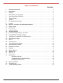
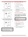
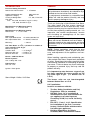
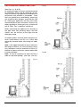
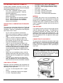
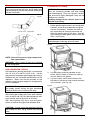
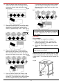
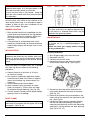
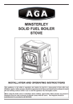
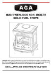
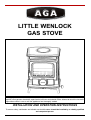
LITTLE WENLOCK
GAS STOVE
This appliance is hot while in operation and retains its heat for a long period of time after use.
Children,
aged or infirm persons should be supervised at all times and should not be allowed to touch the hot work-
ing surfaces while in use or until the appliance has thoroughly cooled.
INSTALLATION AND OPERATION INSTRUCTIONS
To ensure safety, satisfaction and reliable service this stove should be installed by a suitably qualified
and competent person.
TABLE OF CONTENTS
PAGE NO.
1.
Operation Instructions . . . . . . . . . . . . . . . . . . . . . . . . . . . . . . . . . . . . . . . . . . . . . . . . . . . 2
2.
Precautions . . . . . . . . . . . . . . . . . . . . . . . . . . . . . . . . . . . . . . . . . . . . . . . . . . . . . . . . . . . 2
3.
Lighting . . . . . . . . . . . . . . . . . . . . . . . . . . . . . . . . . . . . . . . . . . . . . . . . . . . . . . . . . . . . . . 2
4.
What to do if you smell gas
5.
Vent Safety Shut Off Switch . . . . . . . . . . . . . . . . . . . . . . . . . . . . . . . . . . . . . . . . . . . . . . 3
6.
Technical Data
7.
General . . . . . . . . . . . . . . . . . . . . . . . . . . . . . . . . . . . . . . . . . . . . . . . . . . . . . . . . . . . . . . 4
8.
Pre-Installation Assembly . . . . . . . . . . . . . . . . . . . . . . . . . . . . . . . . . . . . . . . . . . . . . . . . 5
9.
Location. . . . . . . . . . . . . . . . . . . . . . . . . . . . . . . . . . . . . . . . . . . . . . . . . . . . . . . . . . . . . . 5
10.
Minimum Clearances to Combustible Materials . . . . . . . . . . . . . . . . . . . . . . . . . . . . . . . 5
11.
Hearth Fitting. . . . . . . . . . . . . . . . . . . . . . . . . . . . . . . . . . . . . . . . . . . . . . . . . . . . . . . . . . 6
12.
Dimensions . . . . . . . . . . . . . . . . . . . . . . . . . . . . . . . . . . . . . . . . . . . . . . . . . . . . . . . . . . . 7
13.
Chimney’s/Flues . . . . . . . . . . . . . . . . . . . . . . . . . . . . . . . . . . . . . . . . . . . . . . . . . . . . . . . 7
14.
Suitable Materials . . . . . . . . . . . . . . . . . . . . . . . . . . . . . . . . . . . . . . . . . . . . . . . . . . . . . . 7
15.
Use of Existing Chimney’s and Flues . . . . . . . . . . . . . . . . . . . . . . . . . . . . . . . . . . . . . . . 8
16.
Factory-Made Insulated Chimneys . . . . . . . . . . . . . . . . . . . . . . . . . . . . . . . . . . . . . . . . . 9
17.
Ventilation & Combustion Air Requirements . . . . . . . . . . . . . . . . . . . . . . . . . . . . . . . . . . 9
18.
Gas Pipes & Fittings . . . . . . . . . . . . . . . . . . . . . . . . . . . . . . . . . . . . . . . . . . . . . . . . . . . . 9
19.
Meters . . . . . . . . . . . . . . . . . . . . . . . . . . . . . . . . . . . . . . . . . . . . . . . . . . . . . . . . . . . . . . . 9
20.
Gas Pipe Size . . . . . . . . . . . . . . . . . . . . . . . . . . . . . . . . . . . . . . . . . . . . . . . . . . . . . . . . . 9
21.
Connection to Gas Supply . . . . . . . . . . . . . . . . . . . . . . . . . . . . . . . . . . . . . . . . . . . . . . . 9
22.
Gas Soundness Testing . . . . . . . . . . . . . . . . . . . . . . . . . . . . . . . . . . . . . . . . . . . . . . . . . 10
23.
Placement of Coals . . . . . . . . . . . . . . . . . . . . . . . . . . . . . . . . . . . . . . . . . . . . . . . . . . . . 10
24.
Lighting . . . . . . . . . . . . . . . . . . . . . . . . . . . . . . . . . . . . . . . . . . . . . . . . . . . . . . . . . . . . . . 11
25.
Burner Lighting . . . . . . . . . . . . . . . . . . . . . . . . . . . . . . . . . . . . . . . . . . . . . . . . . . . . . . . . 12
26.
Spillage Test . . . . . . . . . . . . . . . . . . . . . . . . . . . . . . . . . . . . . . . . . . . . . . . . . . . . . . . . . . 12
27
Pilot Flame . . . . . . . . . . . . . . . . . . . . . . . . . . . . . . . . . . . . . . . . . . . . . . . . . . . . . . . . . . . 12
28.
Maintenance. . . . . . . . . . . . . . . . . . . . . . . . . . . . . . . . . . . . . . . . . . . . . . . . . . . . . . . . . . 12
. . . . . . . . . . . . . . . . . . . . . . . . . . . . . . . . . . . . . . . . . . . . . . 3
. . . . . . . . . . . . . . . . . . . . . . . . . . . . . . . . . . . . . . . . . . . . . . . . . . . . . . . . 4
Removal of Burner . . . . . . . . . . . . . . . . . . . . . . . . . . . . . . . . . . . . . . . . . . . . . . . . 12
Changing of Burner Injector Orifice. . . . . . . . . . . . . . . . . . . . . . . . . . . . . . . . . . . . 13
Removal of Pilot Burner . . . . . . . . . . . . . . . . . . . . . . . . . . . . . . . . . . . . . . . . . . . . 13
29.
Enamel Cleaning . . . . . . . . . . . . . . . . . . . . . . . . . . . . . . . . . . . . . . . . . . . . . . . . . . . . . . 13
30.
Exploded View . . . . . . . . . . . . . . . . . . . . . . . . . . . . . . . . . . . . . . . . . . . . . . . . . . . . . . . . 14
31.
Trouble Shooting Guide . . . . . . . . . . . . . . . . . . . . . . . . . . . . . . . . . . . . . . . . . . . . . . . . . 15
1
OPERATION INSTRUCTIONS
WARNING:
Fig. 1
Do not operate the stove with the
appliance door open, or if the glass panel in the
front door has been broken or removed.
that the door latch is fully locked.
Ensure
Keep the door
spin valve closed at all times when stove is in
operation.
PRECAUTIONS
1.
Do not touch any part of the stove while in
2.
Children and adults should be alerted to the
3.
operation, except the controls.
3.
hazzards of surface temperatures.
Guards may be required to take account of
the special hazzards that exist in nurseries
4.
and other places where there are young
4.
5.
children, aged or infirm persons.
Curtains or other combustible material should
5.
not be positioned on/or above the appliance at
a distance less than 38” (965mm).
Press the control knob all the way in and
turn anti-clockwise until you hear a clicking
sound.
Keep the control knob pressed for 15-30
seconds, and then release .
If the pilot fails
to remain lighting repeat this action.
With the pilot burner lighting, to establish the
flame hold the control knob in the fully
pressed position with dot pointing towards
Do not use this appliance if any part has been
ignition.
under water, immediately call a qualified ser-
vice technician to inspect the appliance and to
(see Fig.2)
Fig. 2
replace any part of the gas control or system
6.
7.
8.
9.
which has been under water.
Do not store gasoline or other flammable
liquids having flammable vapours near this
stove.
Tools must not be used to turn or operate the
valve control knob.
Use only in a sufficiently ventilated space.
This appliance must be installed in accordance with the rules in force.
10. Read the label and manual provided before
6.
commencing to install or attempting to operate
the stove.
To light the main burner, fully release the
control knob and turn anti-clock-wise to the
required setting.
FAILURE TO DO SO MAY RESULT IN
(see Figs. 3&4)
Fig. 3
PROPERTY DAMAGE OR PERSONAL
INJURY.
LIGHTING
1.
The stove control knob is located at the
2.
The valve is in the off position when the
bottom righthand side looking from the front.
control knob symbol “OFF” is at the datum
point and there is no gas to the pilot or
burner.
main
The knob can only be turned in a
clockwise direction to reach the “OFF”
High Flame Setting
position. (see Fig.1)
2
Fig.4
WHAT TO DO IF YOU SMELL GAS
Low Flame Setting
7.
A.
Turn off the gas mains.
B.
Do not try to light any appliance.
C.
Do not touch any electrical switch.
D.
Open windows.
E.
Do not use any phone in the building.
F.
Immediately call your gas engineer from a
G.
If you cannot reach your gas supplier, call the
To turn off the main burner, turn the control
knob in a clockwise direction to low flame.
(see Fig. 4)
Fig. 5
neighbours phone.
Fire Department.
VENT SAFETY SHUT OFF SWITCH
The
vent
safety
shut
off
switch
location
is
designed to shut down the stove when exposed to
excessive
temperatures
due
to
severe
down
draughts, blocked flues or negative pressure due
to a fresh air shortage.
It must not be disconnect-
ed or isolated in any way.
WARNING:
8.
While pressing the control knob
to
be
isolated
or
adjusted.
Parts to be replaced with identical and/or equiva-
continue
lent original parts.
to turn in a clockwise direction until it stops.
The stove is now off. (see Figs. 5&6)
What to do if the vent safety shut off switch
continually goes off:
Fig. 6
NOTE: During the first light-up period an odour
will arise from the stove, this is due to the materials in the stove drying and curing.
Not
It is advisable
to open a door or window to give extra ventilation
to the room until the odour has gone.
3
A:
Wait for 4 minutes after shut down.
B:
Refer to these lighting instructions for
C:
If stove fails to light repeat the above
D:
If stove fails to light after three attempts
lighting procedures.
procedures.
contact your local Aga Dealer.
TECHNICAL DATA
GENERAL
Pressure Setting From Cold
Natural Gas Inlet Pressure
=
Product Identification No.:
viduals
I2E, G20, 20 mbar/8” wg &
The
=
7.4”/18.5 mbar
imperative
Maximum flow rate
Minimum flow rate
Burner:
=
system
should
be
More
that
control
circulating
air
compartments,
passageways
of
It is
burners
the
room
It
this manual.
NOTE:
3
37.78 MJ/m
Before installation, check that the local
distribution
3
0.505 m /hr
conditions,
nature
of
gas
and
pres-
sure, and adjustment of the appliance are com-
3
0.143 m /hr
patible.
CPD Gas Burner
When installing, operating and maintaining your
Burner Injectors:
Little wenlock Gas Stove, respect basic standards
CAT 18 Bray 320 - N.G.
of safety.
Read these instructions carefully before
commencing installation or attempting to operate
Pilot Injectors
your stove.
Size 3.5 - N.G.
Ignition:
flue
publications may be superseded during the life of
C, 1,013mbar in relation to
=
and
should be noted that the requirements and these
= Class 2
=
may
The complete installation must be done in accor-
gross calorific value of gas.
Calorific Value
and
dance with current Standards and Local Codes.
o
Gas Flow Rates at 15
heater
heater are kept clean.
= 1.5kW/5,118 Btu’s/h
Efficiency:
warranty
sive lint from carpeting, matting material, etc.
= 5.3kW/18,084 Btu’s/h
Min. Input Natural Gas
Natural Gas gross
room
and
Max. Input Natural Gas
product
frequent cleaning may be required due to exces-
1.1”/2.7 mbar
Gross Input
the
inspected before use and at least annually.
Manifold Pressure Minimum Setting
Natural Gas
void
Thank you for buying a Little Wenlock Gas Stove.
Manifold Pressure Maximum Setting
=
will
result in property damage or injury.
I2H, G20, 20 mbar/8” wg (I.E. & G.B.)
Natural Gas
repair
Any adjustments undertaken by unqualified indi-
I.E., G.B., F.R.& B.E
Gas Type:
commissioning,
qualified service technician and installer.
BIIBS
Country of Designation:
Installation,
and maintenance should only be undertaken by a
0063 AS 5164
Appliance Category
N.G.:
WARNING:
8”/20mbar
Failure to do so may result in damage
to property or personal injury and may void the
Piezo Igniter
product warranty.
It is important to note that once a type of gas
has been specified the stove cannot run off
any
other
L.P.G.)
Stove Weight: 138lbs / 62.5 kilos
The
type
burner
of
units
gas.
are
(i.e.
not
Natural
Gas
interchangeable
between Natural Gas or L.P.G.
0063
U.K. Installation
Install in accordance with the:
*
*
The Gas Safety (Installation and Use)
Regulations 1998 (as amended).
BS 5440: Parts 1 & 2, Installation &
maintenance of flues and ventilation for
gas appliances of rated input not
exceeding 70 kW (1st, 2nd & 3rd family
*
gases).
B.S. 5871:
Parts 1, 2 & 3, Specification
for installation of gas fires, convector
heaters, fire/back boiler and decorative
*
4
or
fuel effect gas appliances.
Building Regulations for Britain,
Scotland, Wales and Northern Ireland.
This appliance has been tested and approved
Fig.9
in accordance with the essential requirements
of
Annex
1
in
the
Gas
Appliance
(90/396/EEC) as amended.
Directive
PRE- INSTALLATION ASSEMBLY
Before installing the appliance carry out the following pre-installation assembly:
Fig.7
3.
Ensure the leads to the vent safety shut off
switch located on the back of the stove are
connected and secure. (See Fig. 10).
Fig.10
1.
Open the fire door (item 9), and remove
2.
This stove may be connected to either a
the package of ceramic coals. (See Fig.7)
top or rear flue outlet.
The stove has a rear
flue outlet configuration factory fitted. It may
be changed to a top flue outlet by simply
switching the blanking cap and flue collar as
shown in Fig. 8 & 9.
Fig.8
4.
Position stove in its chosen location and
connect to the chimney/flue system.
LOCATION
There are many conditions to be considered when
selecting the location for you Little wenlock Gas
Stove.
MINIMUM CLEARANCES TO COMBUSTIBLE
MATERIALS (see Figs 11, 12, 13, 14)
CAUTION: Allow adequate clearances for stove
operation
and
annual
servicing
removal and injector removal.
Back wall
burner
6” (150mm)
Left side wall looking from front
5” (125mm)
Alcove or mantle from top of unit
18” (459mm)
Right side wall looking from front
From Corner
5
e.g.
5” (125mm)
5” (125mm)
Fig.14
Fig.11
When installing the stove against a
combustible wall leave a 6” space
Fig.12
Fig.15
between the back of the stove and
When installing the stove against a
the wall for air circulation.
non-combustible wall leave a 2” space
(See Fig.12)
between the back of the stove and the
wall for air circulation.
(See Fig.15)
HEARTH FITTING
Fig.13
This stove MUST be installed on a concrete con-
structional hearth, or on a non-combustible hearth
slab,
minimum
size
27.5”
(500mm)
x
28.8”
(732mm) deep with the fire place opening centrally located.
13mm (
50mm
1
/2”)
(2”)
The hearth material should be at least
thick, the top surface being preferably
above
floor
level
to
discourage
placing of carpets over it. (see Fig.16)
6
the
Fig.16
Fig.17
The chimney and flue pipes intended for use with
this
appliance
should
be
mechanically
robust,
resistant to internal and external corrosion, non-
combustible, and durable under the conditions to
which they are likely to be subjected.
WARNING:
nected
to
a
lation
Only operate this appliance if conproperly
chimney system.
installed
and
of
flues
for
gas
appliances
The instal-
should
accordance with the following standard:
maintained
Do not tamper with the vent
*
safety shut-off system.
be
in
BS 5440 Installation & maintenance of flues
and ventilation for gas appliances of rated
input not exceeding 70kW (1st, 2nd & 3rd
DIMENSIONS
family gases).
Part 1: - Specification for installation of
Part 2: - Specification for installation &
flues.
maintenance of ventilation of gas appliances.
*
B.S. 5871:
Parts 1, 2 & 3, specification for
installation of gas fires, convector heaters,
fire/back boiler and decorative fuel effect
gas appliances.
SUITABLE MATERIALS
A
B
C
D
E
F
Metric (mm)
405
540
430
445
96
335
16
21
2
/8
7
/8
16
17
4
/8
6
/8
3
Mineral Fibre cement pipes conforming to
*
Sheet metal conforming to B.S. 715.
*
Dimensions
Imperial (inches)
*
2
/8
13
the stove outlet. (see fig.17)
the
chimney
or
flue
serving
B.S. 4543 (a galvanised finish is not suitable).
Clay flue linings conforming to I.S. 51 &
*
Pre-cast concrete chimney blocks, incorporat-
*
zontal run should not exceed 300mm (12”) from
of
Insulated metal chimney’s conforming to
B.S. EN 1457 1999.
ed into the building structure.
It is particularly
important that the correct connection block be
If connecting to a rear exit configuration the hori-
height
567.
*
CHIMNEY’S / FLUES
The
B.S.
this
provided at the base of the flue, B.S. 1289.
Cast iron or acid resistant vitreous enamelled
lined mild steel to B.S. 41.
Where
appliance should not be less than 3 meters (10’),
twin
struction
and not more than 11 meters (36’), measured ver-
wall
the
pipes
length
of
are
of
pipe
sheet
located
metal
con-
externally
should not exceed 1m (3’3”) unless it is readily
tically from the outlet to the top of the flue terminal
accessible for renewal.
and having a diameter of 125mm (5”).
Note: Never connect to a chimney or flue system
serving another appliance.
7
USE OF EXISTING CHIMNEYS AND FLUES
Fig.19
(See Figs. 18, 19 & 20)
An existing flue pipe or chimney that has proved to
be satisfactory when used for solid fuel can normally be used for a gas appliance provided that its
construction and condition is acceptable.
Flues
that have proved to be unsatisfactory, particularly
with regard to down draught, should not be used
for venting gas appliances until they have been
examined and any faults corrected.
If there is any
doubt regarding an existing chimney a smoke test
to B.S. 5440:
Part 1 should be carried out.
Before connecting this appliance to a chimney or
flue
pipe
another
which
fuel,
has
the
thoroughly swept.
previously
chimney
or
been
flue
used
pipe
with
must
be
All register plates, restrictor plates, dampers etc.
which
could
obstruct
the
flue
at
a
future
date
should be removed before connecting this appliance.
Note: A flue spigot extension of up to a maximum
total length of 300mm (12”) may be fitted if neces-
sary, provided a minimum clearance of 50mm (2”)
between its open end and the nearest obstruction
is always provided.
Note:
Fig.20
It may be necessary to reline the flue in
order to help avoid spillage.
(see Figs. 19 & 20).
Fig.18
8
*
FACTORY-MADE INSULATED CHIMNEY’S
*
Factory-made insulated chimneys must be con-
*
structed and tested to meet the relevant standards
and recommendations given in:
*
B.S. 7566:
*
*
Installation of factory made
*
chimney’s conforming to B.S. : 4543 for
*
domestic appliances.
Part 1:
Method of specifying installation
Part 2:
Specification for installation design.
Part 4:
Recommendation for installation
B.S. 4089 - L.P.G. hoses and assemblies.
If using an
existing meter have it checked to ensure that the
meter is capable of dealing with the total rate of
gas needed.
GAS PIPE SIZE
This stove has a heat input of less than 7 kW and
therefore does not normally require any additional
It is important that the correct service pipe size be
However, consideration must be given
used for adequate gas supply.
to the local rules in force.
This depends on
the distance between the supply meter and the
appliance relative to the input requirements.
Any air vent must either be connected
The
gas supply to the appliance should be terminated
direct to an outside air supply or to adjacent
near the appliance with an approved safety type
rooms having a permanent vent to the out
service tap.
side.
If there is another combustion appliance
CONNECTION TO GAS SUPPLY
fitted in the same or adjacent room, it will
be necessary to refer to the rules in force to
*
B.S. 6362 - stainless steel tubes.
B.S. 1740 - Wrought steel pipes.
board or by an appointed contractor.
MENTS
*
B.S. 1387 - Steel tubes.
service pipe either by a representative of the gas
VENTILATION & COMBUSTION AIR REQUIRE-
*
equipment.
A suitable gas meter must be connected to the
Specification for site installation.
design and installation.
ventilation.
B.S. 759 - valves, gauges and other safety
METERS
design information.
Part 3:
EN 29453 & I.S.O. 9453 - Soft Solders.
B.S. 669 - flexible hoses, fittings & sockets.
The gas control is located at the bottom right hand
calculate the additional air supply.
side of the unit.
If there is an air extraction fan fitted in the
Check that the mains gas supply
pipe is adequately sized and capable of supplying
room or adjacent rooms where this appliance
enough gas to the appliance when operating on
is fitted, additional air vents may be required
max. rate.
to alleviate the possibility of spillage of products of combustion from the appliance/flue
while the fan is in operation. Refer to the rules
*
WARNING:
in force.
Where such an installation exists, a test for
as this will cause blockage within the stove con-
spillage should be made with the fan or fans
trol, pilot burner, injectors and pipework.
and other gas burning appliances in operation
*
to do so may void product warranty.
at full rate.
If spillage occurs following the above oper-
Fig.21
ation, an additional air vent of sufficient size
to prevent this occurrence should be installed.
GAS PIPES & FITTINGS
Materials used for installation work should be fire
resistant and gas tight and should conform to the
following or their equivalent.
*
I.S. 238, I.S. 239 and prEN 1057 - Copper
*
I.S. 265 - Installation of gas service pipes.
*
Before connecting the stove make
sure the gas supply pipe is clear of grit and debris
tubes.
I.S. 266 - Polyethylene pipes.
9
Failure
WARNING:
To
avoid
pipe
sealing
PLACEMENT OF COALS
compounds
from entering into the gas train, do not apply seal-
WARNING:
ing compound to the first two threads at the tip of
stove
the gas connection.
are
The ceramic coals supplied with this
extremely
durable
and
long
lasting
when fitted properly. They are, however, very del-
icate and can be easily damaged if they are not
Fig.22
handled very carefully.
Handling damage to the ceramic coals is not
covered by warranty.
1.
Before positioning the coals in the combustion
chamber, check for dust particles and grime,
vacuum if necessary.
Position the coals as
per instructions as incorrect placement will
effect the performance of the stove.
Fig.23
Dust off
the inside of the door glass using a clean dry
cloth.
Note:
(see Fig.24)
Exhibit care when cleaning the burner to
avoid blockage or damage of burner parts.
Fig.24
NOTE: Clean off any excess pipe compounds
from connections.
WARNING:
Only connect to gas type indicated
on the rating plate.
GAS SOUNDNESS TESTING
Gas soundness testing should be in accordance
with I.S. 813 (I.E.) and B.S. 6891 (U.K.).
2.
Correct
gas pressure and proper gas supply pipe sizing is
important for the successful performance of this
appliance.
Make
sure
that
the
plumber
or
3.
gas
supplier checks the gas supply line and gas pres-
gas
supply
during
any
gas
soundness
testing at pressures in excess of 50 mbar.
After testing gas supply pipe work, open isolation
valve to stove and carry out gas soundness testing at normal working pressure of 20 mbar.
With
stove
lighting
carry
out
a
leak
test
down-
stream of control using gas leak detection fluid.
CAUTION:
with the holes in the gasket.
Lay the ceramic matrix on the burner with
the holes in the burner lined up with the holes
Fig.25
The appliance must be isolated from
system
burner with the holes in the burner lined up
in the ceramic. (see Fig. 25)
sure at installation.
CAUTION:
Lay the gasket material provided, on the
If using a gas leak detection fluid for
leak testing DO NOT spray solution onto control
body.
10
4.
5.
Place 4 medium coals on the front of the
Lay the two remaining medium coals random-
one corner of each coal resting on a spar.
one corner of the coals touch any other coal.
matrix with their corners touching and also
ly on the matrix ensuring that no more than
(see Fig.26)
(See Fig. 29)
Fig.26
Fig.29
Place 4 large coals on the rear of the matrix
with their corners touching.
The front corner
should over hang the back section of the
matrix by approximately 10mm.
(See Fig.27)
IMPORTANT:
Fig.27
Leave an air space around each
coal to allow easy flow of products of combustion,
too
much
impingement
cause sooting.
10mm
of
flame
on
coals
will
LIGHTING
First Lighting-
Purge air from the supply line as follows:
a.
Open main shut-off valve.
pressure test point.
Unscrew inlet
Leave open inlet test
screw until gas comes.
b.
6.
ately.
WARNING:
Place 3 small coals on 3 of the medium
purge
the
system
near
control knob pressed for 15-30 seconds.
control knob.
action.
Fig.30
Place a medium coal on the medium coal
which does not already have a small coal
Ensure one corner of the medium
coal rests against the large coal behind it.
11
a
Turn anti-
clockwise until you hear a clicking sound.
Fig.28
on top of it.
not
Press in the control knob all the way.
Place the last small
coal on either side of the matrix. (See Fig.28)
7.
Do
naked flame or hot surface.
coals leaving one corner of the small coal
touch the large coals.
When gas comes tighten inlet screw immedi-
Keep
Release
If the pilot fails to light repeat this
WARNING:
Do not operate the stove with the
Fig.31
appliance door open, or if the glass panel in the
CORRECT FLAME
INCORRECT FLAME
front door has been broken or removed.
Ensure the door latch is fully locked.
Keep the
door spin valve closed at all times when the stove
is in operation.
During the first light up period an odour will rise
from the stove, this is due to the materials in the
stove drying and curing.
window
or
door
to
give
It is advisable to open a
extra
room until the odour has gone.
ventilation
to
the
IMPORTANT:
tor will result in a reduced flame which may be
1. With the pilot flame firmly established turn the
insufficient for ignition purposes.
control knob anti-clockwise to the high position.
When the main burner is lighting
adjust con-
MAINTENANCE
trol knob clockwise to a lower setting if
required.
CAUTION: Maintenance of this stove should only
2. If the pilot light is extinguished either inten-
be
tionally or unintentionally no attempt should be
carried
Engineer.
made to light the gas until at least 4 mins. have
out
by
a
qualified/competent
Gas
Isolate the main gas supply before carrying
elapsed.
out any maintenance.
SPILLAGE TEST
NOTE:
Please ensure that the pilot injec-
tor is clear at all times, as a partially blocked injec-
BURNER LIGHTING
Removal of Burner
It is essential that every flue system be
1. Shut off gas supply at the shut off valve.
inspected and tested by the installer upon com-
2. Open door (item 9).
pletion, to ensure that the combustion products
3. Carefully remove the coals.
are completely discharged to the outside atmos-
4. Disconnect the 8mm gas pipe at the back
phere.
of the control under the lip.
When the stove is installed carry out a spillage
(see Fig.32)
Fig.32
test (See Fig.30) as outlined in the following
procedure:
a. Operate stove for a minimum of 10 mins.
at maximum setting.
b. Run all other combustion appliances and/or
extraction fan/s fitted in the room or adjacent
rooms at full setting e.g. clothes dryers, fur-
c.
naces etc.
Close windows and external doors.
d. With a smoke match, joss stock or smoke
puffer run around 1” (25mm) from the edge
of the down draught opening. (See Fig. 30).
5. Disconnect the snap switch leads from the
e. If all the smoke is pulled into the down draught
snap switch located at the back of the stove.
opening, there is no spillage.
(See Fig. 33).
6. Remove the two M6 wing nuts located on the
under side of the stove on the right and on the
PILOT FLAME
NOTE:
left.
The pilot flame should be a steady blue
with the left side and gradually turning the
flame which has contact with the upper 3/8” of the
thermopile.
(See Fig.33).
7. Carefully lift up the burner assembly starting
assembly anti-clockwise until the left side of the
(See Fig 31)
assembly is facing towards the door opening.
(See Fig.35, 36, 37).
12
Fig.38
Fig.33
Fig.34
Changing of Burner Injector Orifice
With the complete burner assembly removed as
per Fig. 35, 36, 37.
1.
Disconnect the 6mm gas feed pipe from the
2.
Slacken the 6mm gas feed pipe to the
3.
control to injector.
(see Fig. 38).
injector at the control.
Remove Injector from burner.
Removal of Pilot Burner
1.
Fig.35
2.
Unscrew the two
pilot burner.
1
/4”
slotted head screw from
(See Fig.39)
Disconnect the 6mm gas feed pipe.
Fig.39
ENAMEL CLEANING
Fig.36
General cleaning must be carried out when the
stove is cool.
If this stove is finished in a high gloss vitreous
enamel, to keep the enamel in the best condition
observe the following tips:
1.
Wipe over daily with a soapy damp cloth,
2.
For stubborn deposits a soap impregnated
3.
Fig.37
followed by a polish with a clean dry duster.
pad can be carefully used on the vitreous
enamel.
Use only products recommended by the
Vitreous Enamel Association, these products
carry the vitramel label.
ASSOCIATION
4.
DO NOT USE ABRASIVE PADS OR OVEN
CLEANSERS CONTAINING CITRIC ACID
ON ENAMELLED SURFACES.
ENSURE
THAT THE CLEANSER MANUFACTURERS
INSTRUCTIONS ARE ADHERED TO.
13
LITTLE WENLOCK GAS EXPLODED VIEW
1.
2.
3.
4.
5.
34
6.
7.
8.
9.
10.
11.
12.
13.
14.
35
15.
16.
17.
18.
19.
39
36
20.
37
Leg
21.
Front Frame
22.
Blanking Plate
23.
Flue Spigot
Hob
Back Casting
Burner NG
26.
Aga Stove Badge
28.
1/4” BSP Nut
29.
Mains Inlet Bracket
30.
Vent Switch Bracket
31.
Rating Plate Bracket
32.
Vent Switch
33.
Coal Matrix
34.
Door Assembly
35.
Control Plate
36.
Serial Number Plate
37.
Data Plaque
38.
Front Baffle
39.
Back Baffle
38
Tie Rod (M8*260mm)
Mains Inlet Pipe
27.
Base
Long Tie Bolt
24.
25.
LH & RH Side Panels
Door Catch
Inlet Valve
Dia. 8 x 6mm Olive
Spin Valve
Door Hinges
Door Glass
Door Handle
Glass Clips
Burner Gasket
Thermocouple C/W Leads
Pilot Injector
Pilot Electrode
Gas Valve
Control Valve Knob
23
4
3
7
13
5
11
20
18
10
6
12
22
19
14
28
2
33
25
24
21
27
17
16
9
31
8
30
26
1
32
15
29
14
6
TROUBLE SHOOTING GUIDE
PROBLEM
POSSIBLE CAUSE
SOLUTION
Pilot will not light
No gas
Check gas is turned on.
Safety interlock preventing
Operation.
Control knob not fully pressed.
Ensure control knob is being fully
Disconnected piezo igniter.
Connect piezo cable.
Insufficient gas pressure.
Call your qualified service technician.
Blocked orifice.
Call your qualified service technician.
Air in gas lines
Damaged pilot hood.
Defective control valve.
Faulty piezo igniter
Pilot lights but goes out
when the control knob
is released.
Insufficient flame impingement on
thermocouple.
Incorrect position of thermocouple.
Weak milli volt current.
Poor electrical contacts.
Burners will not light.
Wait 5 minutes & attempt to relight.
Control knob may not be
pressed.
Call your qualified service technician.
Call your qualified service technician.
Call your qualified service technician.
Call your qualified service technician.
Call your qualified service technician.
Call your qualified service technician.
Call your qualified service technician.
Call your qualified service technician.
Turn control knob anti-clockwise to a
turned to correct position.
heat output setting.
Incorrect inlet pressure.
Call your qualified service technician.
Air in gas lines.
Blocked orifice.
Faulty control valve.
Call your qualified service technician.
Call your qualified service technician.
Call your qualified service technician.
Heater operates normally
Blocked flue.
Clear blockage.
10 minutes.
switch activating.
Call your qualified service technician.
Noise in pilot/burners
Excessive gas pressure.
Call your qualified service technician.
Draught hood spillage.
Chimney or venting system not
Increase height.
then goes out within
Insufficient draught leading to the
Defective vent safety switch.
high enough.
Call your qualified service technician.
Chimney or venting system blocked Clear blockage.
Leaks in chimney or venting
Seal joints.
Insufficient air supply when other
Call your qualified service technician.
system joints.
air using appliances are in
operation.
Flame characteristics:
Hard sharp flame
Yellow flame
Lifting flame
Small sharp flame
Excessive primary air.
Reduce air intake.
Insufficient primary air supply.
Increase air intake.
Excessive gas pressure.
Call your qualified service technician.
Semi clogged gas supply line.
Call your qualified service technician.
Over sized burner orifice.
Clogged burner orifice.
Excessively low gas pressure.
Call your qualified service technician.
Call your qualified service technician.
Call your qualified service technician.
Aga,
Station Road,
Ketley, Telford,
Shropshire, TF1 5AQ,
UK
15
N00398AXX
Rev:002
DP 060822