1
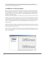
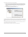
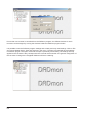
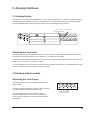
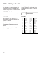
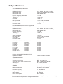
Installation guide
CAUTION
RISK OF ELECTRIC SHOCK
DO NOT OPEN
ATTENTION
: RISQUE DE CHOCK ELECTRIQUE NE PAS OUVRIR
CAUTION: TO REDUCE THE RISK OF ELECTRIC SHOCK
DO NOT REMOVE COVER (OR BACK).
NO USER-SERVICEABLE PARTS INSIDE.
REFER SERVICING TO QUALIFIED SERVICE PERSONNEL.
The lightning flash with arrowhead symbol,
within an equilateral triangle, is intended to
alert the user to the presence of uninsulated
"dangerous voltage" within the product's
enclosure that may be of sufficient magnitude
to constitute a risk of electric shock to persons.
The exclamation point within an equilateral
triangle is intended to alert the user to the
presence of important operating and
maintenance (servicing) instructions in the
literature accompanying the product.
IMPORTANT SAFETY AND INSTALLATION INSTRUCTION
SAVE THESE INSTRUCTIONS
INSTRUCTIONS PERTAINING TO RISK OF FIRE, ELECTRIC SHOCK, OR INJURY TO PERSONS
WARNING – when using electric products, basic precautions should be followed, including the following:
1. Read all of the safety and installations instructions and explanation of graphic symbols before using the product.
2. The product must be grounded. If it should malfunction or breakdown, grounding provides a path of least resistance for
electric current to reduce the risk of electric shock. This product is equipped with a power supply cord having an equipmentgrounding
conductor and a grounding plug. The plug must be plugged into an appropriate outlet which is properly installed and grounded
in accordance
with all local codes and ordinances.
DANGER – Improper connection of the equipment-grounding can result in a risk of electric shock. Do not modify the plug
provided with the product – if it will not fit the outlet have a proper outlet installed by a qualified electrician. Do not use an
adapter which defeats the function of the equipment-grounding conductor. If you are in doubt as to whether the product is
properly grounded, check with a qualified serviceman or electrician.
3. Do not use this product near water – for example, near a bathtub, washbowl, kitchen sink, in a wet basement, or near a swimming pool, or the like.
4. This product should only be used with a stand or cart that is recommended by the manufacture.
5. This product, either alone or in combination with an amplifier and speakers or headphones, may be capable of producing
sound levels that could cause permanent hearing loss. Do not operate at a high volume level or at a level that is uncomfortable.
If you experience any hearing loss or ringing in the ears, you should consult an audiologist.
6. The product should be located so that its location or position does not interfere with its proper ventilation.
7. The product should be located away from heat sources such as radiators, heat registers, or other products that produce heat.
8. The product should be connected to a power supply only of the type described in the operating instructions or as marked on
the product.
9. The power-supply cord of the product should be unplugged from the outlet when left unused for a long period of time. When
unplugging the power supply, do not pull on the cord, but grasp it by the plug.
10. Care should be taken so that objects do not fall and liquids are not spilled into the enclosure through openings.
11. The product should be serviced by qualified service personnel when:
A. The power supply cord or plug has been damaged, or
B. Objects have fallen, or liquid has spilled into the product, or
C. The product has been exposed to rain, or
D. The product does not appear to be operating normally or exhibits a marked change in preformance, or
E. The product has been dropped, or the enclosure damaged.
12. Do not attempt to service the product beyond that described in the user maintenance instructions. All other servicing should
be referred to qualified service personnel.
13. WARNING - Do not place objects on the power supply cord, or place the product in a position where anyone could trip over,
walk on, or roll anything over cords of any type. Do not allow the product to rest on or be installed over cords of any type. Im-
3
© 2005 All rights reserved. Merging Technologies and Sphynx 2 are registered
Trademarks of Merging Technologies S.A.
Product features and specifications are subject to change without notice.
Merging Technologies S.A shall not be liable for technical or editorial errors contained herein, nor for
incidental or consequential damages resulting from the furnishing, performance or use of this manual.
Company Address: Merging Technologies S.A. Le Verny, CH-1070 Puidoux, Swizerland.
Fax. +41 (0)21 946 04 45. Web: www.merging.com.
DAD No. 973004010 rev. 1
4
Contents
1. INTRODUCTION
7
BEFORE YOU START
GENERAL INTRODUCTION
WELCOME
7
7
7
2. CONTROL SOFTWARE INSTALLATION
7
2.1 PC RECOMMENDATION
2.2 PROGRAM INSTALLATION
7
8
3. HARDWARE INSTALLATION
9
3.1 REAR PANEL
9
Installing I/O cards
Connecting the analog audio cables
Connecting the digital audio cables
Connecting the digital sync input/output
Connecting the Power Cable
Connecting the RS422 cable for remote control
9
10
10
10
10
10
3.2 THE FRONT PANEL
11
4. DADMAN CONTROL PROGRAM
12
5. ANALOG INTERFACES
15
5.1 ANALOG INPUTS
15
5.2 ANALOG OUTPUT MODULE
15
6. INTERFACE SPECIFICATIONS
16
6.1 RS422 CONTROL INTERFACE
6.2 8 CH TDIF DIGITAL I/O MODULE
6.3 MADI DIGITAL I/O MODULE
6.4 8 CH SDIF3 DIGITAL I/O MODULE
7.1 8 CH ADAT DIGITAL I/O MODULE
7.1 8 CH AES3 DIGITAL I/O MODULE
16
16
17
17
18
18
6. SPECIFICATIONS:
19
The Power button
LED’s and Unit ID at the front panel
Adjusting the Line Input
Adjusting the Line Output
11
11
15
15
5
6
1. Introduction
Welcome
Congratulations, and thank you for purchasing the Merging Technologies Sphynx 2 audio converter. The
Sphynx 2 is an extremely powerful 8-channel audio converter for independent simultaneous analogto-digital (A/D), and optional digital-to-analog (D/A) conversion. The Sphynx 2 has a modular structure
enabling the use of up to 7 I/O modules.
For a more detailed description of the Sphynx 2, please look at the Merging website www.merging.com.
General introduction
The Sphynx 2 is jointly developed by Merging Technologies and Digital Audio Denmark (DAD) and is one
of the most advanced and sonically pure converter ever developed.
The sample rate capabilities of this unit allow for 44.1kHz, 48kHz, 88.2kHz, 96kHz, 176.4kHz, 192 kHz,
DSD 1-bit 64FS, DSD 1-bit 128fs and even supports the new Philips DXD (Digital eXtreme Definition) 24
bit, 352.8kHz format for SACD production.
Sphynx 2 must be controlled from within the Pyramix screen via a simple RS422 link using DAD’s
DADman PC remote control software.
The modular design of the Sphynx 2 offers 8 channels of A to D conversion with the option of inserting up
to two 4 channel D to A cards resulting in the most cost-effective means of achieving 8 channels of ADDA in 1-bit DSD.
A range of audio interfaces for external equipment are available including MADI, SDIF3, AES-EBU, TDIF
and ADAT. Pyramix DSD users will probably require the MADI interface offering 8 channels of DSD/DXD
in a single MADI link and allowing two units to be synchronised using a second MADI link for the Pyramix
16 channel DSD system.
Before you start
· Place your Sphynx 2 on a hard and dry surface or mount it into a 19” rack, and leave plenty of room
for ventilation.
· In order to meet the EMC requirements of directives 89/336/EEC and 93/68/EEC, and in order to
obtain the high performance the Sphynx 2 is capable of, you must use good quality correctly shielded
cables for all external connections when installing the Sphynx 2. For the power connection, a
normal unshielded power cable with a proper ground can be used.
· Make sure that your sound system is at a safe volume level.
The following sections describe how to get started with installing and operating your Sphynx 2.
2. Control software installation
2.1 PC recommendation
The DADman software operates on any Pentium computer with Windows XP installed and needs one
free USB or RS422 port.
7
2.2 Program installation
This section will take you through the installation procedure for the DADman PC software program.
The Sphynx 2 is controlled from a PC via RS422. Three solutions for this can be provided by Merging.
1. VScom USB USB I/O adapter with one RS422 break out (one RS422 output).
2. VScom USB USB I/O adapter with four RS422 break out (four RS422 outputs).
3. Antona RS232 to RS422 converter (RS232 from the computer com port)
VScom USB to RS422 I/O adapter from Easy Sync Ltd.:
·
Install the USB driver software provided on the Easy Sync driver CD .
It is recommended to first connect the USB link between the computer and the VScom USB I/O
adapter, then follow the instructions, if any, generated by Windows XP. If/when prompted for the
driver file, choose the driver from the CD. Do not connect the Sphynx 2 to the USB/RS422 converter during this software installation. Windows may install the driver automatically.
Antona RS232 to RS422 converter
·
The Antona RS232 to RS422 converter does not need additional software. Please look at the Appendix “Interface Specifications” to check pin-outs for the connection between the Antona RS232
to RS422 converter and the Sphynx 2.
The DADman remote control program
1. Install the DADman program from the CD provided by following the instructions on the screen.
2. Create a shortcut for the DADman program on the desktop (find the DADman icon: Start/All
Programs/DADman/dadman.exe. Press Ctrl and drag the icon to the desktop).
3. Double click at the DADman icon.
4. In the top left corner of the browser pane there is a + marked entry “Communications ports”. Click
on the + in order to see the different communication ports on the computer.
In the example below one Easy Sync USB to four RS422 converter is connected to the computer.
The software for the USB to RS422 converter and the DADman PC program is now installed correctly .
8
3. Hardware Installation
This section will take you through installation of your Sphynx 2. We will describe how to connect the
analog and digital audio cable, and how to mount additional I/O modules.
3.1 Rear Panel
Installing I/O cards
If you need to install or change an I/O module the following procedure must be used.
Place the Sphynx 2 on a dry, steady, horizontal surface. Turn off the power and remove all cables. On
the rear panel of the Sphynx 2 there are 7 slots for I/O card mounting. The remote control module must
always be installed in the converter. Free slots are fitted with Blanking Plates.
A drawing of the Rear Panel can be seen below:
MAIN POWER
SWITCH
AES11 SYNC
INPUT
REMOTE CONTROL
VIDEO SYNC
RS422
INPUT
AC POWER
CONNECTOR
Video in
WORDCLOCK
SYNC INPUT
ANALOG INPUTS
AES11 in
Remote
control
WC in
ANALOG OUTPUTS
WC out
WORDCLOCK
SYNC OUTPUT
Analog in 1
2
3
4
Analog in 5
6
7
8
RS-422
MADI I/O
1/5
Analog
2/6
out
3/7
4/8
1/5
Analog
2/6
out
3/7
4/8
BLIND PLATES FOR
I/O MODULE SLOTS
ANALOG OUTPUT LEVEL
ADJUSTMENT SCREWS
ANALOG INPUT LEVEL
ADJUSTMENT SCREWS
There are 2 different sizes of I/O module: 1-slot modules and 2-slot modules. Decide where to place the
module. (When mounting a 2-slot I/O module make ensure there are 2 free slots, one above the other, on
the back panel of the Sphynx 2.)
To remove blanking plates for I/O module slots, remove the 2 screws at each side of the plate. Use a
posidrive screwdriver (no. 1). Only remove the number of blanking plates necessary to fit the I/O module.
All slots must be covered with a blanking plate or have an I/O module fitted before the unit is powered up.
It is very important to carefully insert the I/O card horizontally into the Sphynx 2. There are 3 guides
inside the Sphynx 2 to help guide the I/O card correctly into place. Do not use force to insert the I/O card.
This may damage the card.
When the cover plate of the I/O card covers the hole created by removing the blanking plate, the
2 (1 slot) or 4 (2 slots) screws from the blanking plate are used to secure the I/O card. Tighten the screws
carefully and be careful not to damage the threads.
The I/O card is now properly installed.
9
Connecting the analog audio cables
Turn down the sound system volume, before rigging the Sphynx 2’s analog audio cables. On the right
side of the rear panel, you will find 8 balanced XLR input connectors marked 1 to 8. These analog inputs
correspond to the 8 channels, and can be used to connect a balanced line input signal (+12 to +30 dBu).
The input level can be adjusted using the small adjustment screw next to the XLR input connectors.
If any of your I/O cards are DA modules, you should also connect the balanced XLR connectors at this
point.
Connecting the digital audio cables
If one or more I/O card is a digital audio interface, you should also connect the relevant cables to the
appropriate connectors.
Connecting the digital sync input/output
On the left side of the rear panel, you will find the Word Clock external synchronisation input and output
connectors marked WC in and WC out, the AES 11 input connector marked AES11 in and the Video
Black and Burst input connector marked Video in.
If you wish to synchronise your Sphynx 2 to a WordClock signal, connect this signal to WC in through the
BNC socket. The Word Clock signal can be 44.1, 48, 88,2 or 96 kHz +/- 10%.
If you want to use AES11 as external source for synchronising for the Sphynx 2 connect an AES11 signal
to the XLR connection market AES11 in.
To synchronise the Sphynx 2 to a Video Black and Burst signal connect the signal to the Video in socket
with a BNC cable.
To use the Sphynx 2 as master studio clock for other units, connect these units using a BNC cable to WC
out. The Sphynx 2 will generate a synchronising signal with the same frequency used for the A/D or D/D
conversion with a precision better than 10 ppm.
The Word Clock output can alternatively serve as SuperClock output. In the DADman program you
choose between WordClock and SuperClock output for the BNC WC out connector.
There will always be a signal on WC out. Either a WordClock or a SuperClock signal. This means that
the Sphynx 2 can convert a Video Black Burst or an AES11 signal to a WordClock or a SuperClock signal.
Connecting the Power Cable
The Sphynx 2 runs on 90-260 V, 50-60 Hz AC voltage. Excessive voltages can seriously damage the
Sphynx 2, so make sure that your AC power matches the voltage of your Sphynx 2.
When you connect the power, use the cable you received with your Sphynx 2 and plug it into a grounded
outlet. For safety and EMC reasons, and to prevent audio hum, the system must be properly grounded.
Connecting the RS422 cable for remote control
The Sphynx 2 must be controlled from a PC via RS422.
Merging can provide one of three alternative solutions:
1. Easy Sync USB to one RS422 break out (one RS422 output).
2. Easy Sync USB to four RS422 break out (four RS422 outputs).
3. Antona RS232 to RS422 converter (RS232 from the computer com port)
10
The pin-out at the Easy Sync USB to RS422 converter is equivalent to the Sphynx 2 RS422 connector
pin-out. In this case simply connect the USB cable between the Easy Sync USB to RS422 converter
and a USB port on the computer, and connect the Sphynx 2 RS422 input to the output of the Easy Sync
converter using a one-to-one RS422 cable.
RS422 can be used for communication between the Sphynx 2 and the computer to a maximum distance
of 100 meters.
3.2 The front panel
When you have connected the power, the RS422, and the audio cables, set the main switch on the rear
panel to 1 (on) and press the power button on the front panel in order to turn on the Sphynx 2.
Power
Sample rate
Channel status
Communication
Synchronization Unit ID
After start-up the Sphynx 2 will perform an internal calibration for about 20 seconds. This is indicated by
the small blue triangle in the Merging logo and a dot in the LED display blinking. It is recommended to
leave the Sphynx 2 on for approximately 5 minutes in order to warm up, and then to change the samplerate in the DADman program (e.g by setting the Sphynx 2 to internal sync. mode, and changing the
sample rate). This will cause the converter to recalibrate, and improve the dynamic range by 1 to 2 dB.
The Sphynx 2 has a non-volatile memory system (EEPROM) enabling the converter to remember the
active settings. After a power up, the Sphynx 2 will restore the settings to the same state as when it was
turned off. The settings of the Sphynx 2 are stored in the EEPROM approx. 3 min after a settings change
has been made via DADman. This way the EEPROM will have a lifetime of more than 10 Years. It is also
possible to store the active setting immediately by briefly pressing the front panel Power button.
The Power button
Pressing the Power button at the left side of the front panel puts the Sphynx 2 into stand-by mode,
removing power from the main electronic circuits. For security reasons (to avoid accidental turn-off)
the Power button has to be activated for approximately 3 seconds in order to enter stand-by mode.
If the front panel Power button is pressed when in stand-by mode, the converter re-enters the operational
mode, with power restored to all circuits. (If the main switch on the rear panel is switched off there will be
no power on the Sphynx 2).
LEDs and Unit ID at the front panel
On the front panel there are a number of LEDs showing AD input overload (1 sample overs) , AD input
activity (- 40 dBfs), DA activity, and DA carrier for each of the 8 channels.
The Sample rate, the Synchronisation source, the Synchronisation alarm, DA unlocked, and
Communication active are also indicated by LEDs.
The Synchronisation alarm LED indicates if the sync signal is not availabe or if it is out of range in
relation to the supported sample frequencies. The DA unlocked alarm indicates if the A to D and D to A
sample frequencies differ.
11
At the right-hand side of the front panel an alphanumeric display shows a unit ID. Multiple
converters with different Unit ID’s can be controlled from the DADman program at the same time.
The Unit ID is set in the DADman program.
4. DADman control program
Note: The Sphynx 2 is an OEM product manufactured for Merging Technologies by Digital Audio
Denmark. Digital Audio Denmark also manufactures a similar Audio Converter under the Digital
Audio Denmark brand name. This unit is called Axion. The DADman program identifies these two
converters in the same manner, since a Sphynx 2 is internally labeled with a serial number that
identifies it as an Axion converter.
The Sphynx 2 will therefore appear in the DADman remote control program as an Axion converter.
DADman is a generic software program that can control all the remote controlled audio converters
manufactured by DAD. Thus, different models of converters can be connected at the same time.
When a connection is established between the DADman program and the converters, the DADman
program will investigate the connected converters and upload the converter settings into the
DADman program.
By double clicking on the different communication port entries or clicking on the small + to the left
of each Communication port entry, the DADman program will establish communication between the
program and the connected converters.
If the connection is established successfully, an icon and a text label corresponding to the Axion/
Sphynx 2 converter will appear. If no converter is attached to the selected communication port, the
text: no units will appear.
12
By right-clicking on the converter icon (or text) it is possible to:
1. Open a remote control window in the DADman program for the corresponding Axion/Sphynx 2.
2. Synchronise the user settings between the DADman program and the corresponding converter.
However, this also happens automatically when the connection between the DADman program
and the corresponding Sphynx 2 is established, or if the connection is interrupted, and reestablished.
3. Set the Properties for the connected Axion/Sphynx 2.
4. Copy and/or paste user settings between different converters.
If you click on Properties a new window will open. Here you can see the serial number for the connected
converter and you can set the unit number and unit name which will appear in the DADman program. In a
multi channel setup with many converters it might be an idea to call the converters Ch. 1-8, Ch 9-16 and
so on.
It is also possible to change the unit ID number and the unit name for the corresponding converter. The
unit ID is always shown at the front panel of the Sphynx 2.
Note that the serial number of the Sphynx 2 is infact an Axion serial number.
13
If more than one converter is controlled from the DADman program, the different windows for each
converter can be arranged by moving the windows inside the DADman program window.
It is possible to save the DADman program settings and to load previously saved settings. Click on File
and choose between Open, Save and Save As in the menu. The Save command will save all settings
in DADman program. The Open command will open a previously saved setting. The settings are only
applied to the converters if they correspond to the converter serial number or the generel configuraion of
the converter. If settings are not applied DADman will issue a warning.
14
5. Analog interfaces
5.1 Analog Inputs
The input level can be precisely adjusted on the rear panel of the Sphynx 2. Please note that the setting
potentiometers are delicate and must be operated with care. Only trained personnel should undertake
this work. Note that the warranty of the unit does not cover damage to these controls.
ANALOG INPUTS
ANALOG LEVEL
ADJUSTMENT SCREWS
Video in
AES11 in
Remote
control
WC in
Analog in 1
2
3
4
Analog in 5
6
7
8
RS-422
WC out
Adjusting the Line Input
The Input line level can be adjusted between +12 and +30 dBu. In the DADman program system menu
the maximum line level can be set to the range 12 to 21 dBu or 21 to 30 dBu.
Use the back-panel multi-turn adjustment screws in order to fine tune the maximum input level within the
range +12 and +21 dBu, or +21 and +30 dBu.
Turn the adjustment screw clockwise in order to raise the analog input gain or turn the adjustment screw
counter clockwise in order to lower the analog input gain.
5.2 Analog output module
Adjusting the Line Output
The analog line output can be adjusted between +12
and +27 dBu.
Use the multi-turn adjustment screws on the back panel
in order to adjust the maximum output level.
Turn the adjustment screw clockwise in order to
increase analog output level or turn the adjustment
screw counter clockwise in order to decrease analog
output level.
1 /5
Analog
2 /6
out
3 /7
4 /8
ANALOG OUTPUT LEVEL
ADJUSTMENT SCREWS
15
6. Interface specifications
6.1 RS422 control interface
In RS422 communication the Sphynx 2 must always be slave and the computer the master.
RS422 Pin out Sphynx 2:
Baud rate
Cable length:
Connector Type:
Pin 1: RX- (input)
Pin 2: RX+ (input)
Pin 3: TX+ (output)
Pin 4: TX- (output)
Pin 5: GND
Pin 6: NC
Pin 7: NC
Pin 8: NC
Pin 9: NC
19.2 Kbaud
<100 meter
9 pole D-Sub Female
Pin 5
Pin 9
Pin 1
Pin 6
For interfacing to the VScom/Easysync USB to RS422 I/O adapter a 1:1 male-femal 9 pin D-sub cable
must be used.
If you want to use an Antona RS232 to RS422
converter for controlling the Sphynx 2, you will
require a special cable between the Sphynx 2 and
the Antona converter.
RS422 pin out for the Antona RS232 to RS422
converter in master mode:
Pin 1: GND
Pin 2: RXPin 3: TX+
Pin 4: NC
Pin 5: GND
Pin 6: NC
Pin 7: RX+
Pin 8: TXPin 9: +V
6.2 8 ch TDIF digital I/O module
The 8 channel TDIF I/O module makes it possible
to interface to equipment with a standard Tascam
TDIF interface. The module fully supports the
original TDIF 1 standard, the TDIF 96 extension
as well as the TDIF double speed format. The
module supports 8 channel I/O at 44.1 kHz or 96
kHz.
TDIF I/O Specifications:
At 88.2 and 96 KHz the two TDIF interfaces are
required if the TDIF mode is TDIF-1 or TDIF 96. In
this case channel 1-4 is interfaced via connector
1, and channel 5-8 via connector 2.
Only a single interface connection is needed for
the TDIF DS mode, and in all three modes at 44.1
and 48 kHz sample rates.
TDIF mode is selected via DADman.
The pin out format of the D25 connector is
compatible with the TDIF-1 specification.
16
Connectors:
Formats:
Sample Rates:
1 x 25-pin female D-sub
TDIF-1, TDIF96, TDIF DS
44.1 to 96 kHz
TDIF I/O Pin out:
Rear plate
(Con. 1)
1
(Con. 2)
TDIF
2
6.3 MADI digital I/O module
The MADI digital I/O module is capable of interfacing the 8 AD and DA channels of the Sphynx
2 in blocks of eight to any of the 56 channels
available in the MADI format in standard mode or
any of the up-to 64 channels when operating in
extended mode. The allocation can be set independently for input and output. The interface will
pass all unused channels from the input to the
output connector, with a latency of a few samples.
All module settings are made via DADman.
The physical connection is made via two BNC
connectors. One for input and one for output.
Rear plate
MADI I/O Specifications:
Connectors:
Formats:
2 x BNC, 50 Ohm
AES10-96
Merging/Sony DSD64 mapping
Merging DXD mapping
Sample Rates: 44.1 to 192 kHz
6.4 8 ch SDIF3 digital I/O module
The 8 channel SDIF3 I/O module is able to interface all 8 input and output channels of the Sphynx 2 according to the SDIF3 specification. The
connection is made via two 25 pin female D-sub
connectors. Each connector can interface 4 input
and output channels.
Rear plate
SDIF3 I/O Specifications:
Pin out table
Connectors:
Formats:
Sample Rate:
2 x 25-pin female D-sub
DSD64 and DSD128
2.288 and 4.576 Mhz
SDIF3 I/O Pin out:
The connector is compatible with the Merging
D25 to BNC break out cable. Interfacing can also
be made directly to the Mykerinos cards by using
a 1:1 male-male D-sub cable with 8 input and 8
output 50 Ohm coaxial cables
Pin 13
(Con. 1)
Pin 1
(Con. 2)
SDIF3
1-4
Pin 25
Pin 1
5-8
Pin 14
Pin no.
1
2
3
4
5
6
7
8
9
10
11
12
13
14
15
16
17
18
19
20
21
22
23
24
25
Con. 1
Con. 2
DOUT 1+
DOUT 2+
DOUT 3+
DOUT 4+
NC
NC
GND
NC
NC
DIN 4+
DIN 3+
DIN 2+
DIN 1+
GND
GND
GND
GND
NC
NC
NC
NC
GND
GND
GND
GND
DOUT 5+
DOUT 6+
DOUT 7+
DOUT 8+
NC
NC
GND
NC
NC
DIN 8+
DIN 7+
DIN 6+
DIN 5+
GND
GND
GND
GND
NC
NC
NC
NC
GND
GND
GND
GND
17
6.5 8 ch AES3 digital I/O module
The 8 channel AES3 I/O module is able to interface all 8 input and output channels of the Sphynx 2 according to the AES3 specification. The
connection is made via a 25 pin female D-sub
connector. The pin-outs can be set for compliance
with 3 different pin allocation formats.
AES3 I/O Specifications:
Connectors:
Formats:
Sample Rates:
Rear plate
The pin-out format of the D25 connector is
selected by the position of the internal flat cable
connector on the PCB.
The first position is the one closest to the rear
plate. The second position is in the middle. In
the 3 positions the D25 connector pin-out is
compatible with the following manufacturers
(typical)
Pos. 1 Yamaha, Mackie, Akai and Apogee
Pos. 2 Merging (factory default)
Pos. 3 Tascam and Digidesign
Pin 13
Pin 1
Pin 25
Pin 14
AES/EBU I/O
1 x 25-pin female D-sub
AES3
44.1 to 96 kHz
AES3 I/O Pin out:
18
In the Merging pin out position 2, the connector
is compatible with the Merging D25 to XLR break
out cable. Interfacing can also be made directly
to the Mykerinos cards by using a 1:1 male-male
D-sub cable.
Pin out table
Pin no.
1
2
3
4
5
6
7
8
9
10
11
12
13
14
15
16
17
18
19
20
21
22
23
24
25
Pos. 1
Pos. 2
Pos. 3
DIN 1/2+
DIN 3/4+
DIN 5/6+
DIN 7/8+
DOUT 1/2+
DOUT 3/4+
DOUT 5/6+
DOUT 7/8+
NC
GND
NC
GND
GND
DIN 1/2DIN 3/4DIN 5/6DIN 7/8DOUT 1/2DOUT 3/4DOUT 5/6DOUT 7/8GND
GND
GND
GND
DOUT 1/2+
DOUT 3/4+
DOUT 5/6+
DOUT 7/8+
GND
GND
NC
GND
GND
DIN 7/8+
DIN 5/6+
DIN 3/4+
DIN 1/2+
DOUT 1/2DOUT 3/4DOUT 5/6DOUT 7/8GND
GND
GND
GND
DIN 7/8DIN 5/6DIN 3/4DIN 1/2-
DOUT 7/8+
GND
DOUT 5/6DOUT 3/4+
GND
DOUT 1/2DIN 7/8+
GND
DIN 5/6DIN 3/4+
GND
DIN 1/2NC
DOUT 7/8DOUT 5/6+
GND
DOUT 3/4DOUT 1/2+
GND
DIN 7/8DIN 5/6+
GND
DIN 3/4DIN 1/2+
GND
7. Specifications:
A/D CONVERSION, LINE INPUT
PCM resolution
PCM sample-rates
DSD sample-rates
DXD sample-rates
Dynamic range (A), PCM
Dynamic range (A), DSD, DXD
THD+N (A)
Cross talk
Input impedance
Max. input level
Connectors
Processing delay
24 bit
44.1, 48, 88.2, 96, 176.4, 192 kHz
2.8224 & 5.6448 MHz (64 & 128 fs)
24 bit at 352.8 kHz
> 121 dB
> 117 dB
< -115 dBfs
< -120 dB
> 15 k Ohm
+12 to 30 dBu, adjustable
XLR (pin 2 hot)
< 1.0 ms
D/A CONVERSION, LINE OUTPUT (Optional)
PCM resolution
PCM sample-rates
DSD sample-rates
DXD sample-rate
Dynamic range (A)
THD+N (A)
Cross talk
Output impedance
Max. output level
Connectors
Processing delay
24 bit
44.1, 48, 88.2, 96, 176.4, 192 kHz
2.8224 & 5.6448 MHz (64 & 128 fs)
24 bit at 352.8 kHz
> 117 dB
< -103 dB
< -120 dB
< 40 Ohm
+12 to 27 dBu, adjustable
XLR (pin 2 hot)
< 1.0 ms
FREQUENCY RESPONSE A/D AND D/A
Fs 44.1kHz,
20-20 kHz:
Fs 48kHz,
20-21.5 kHz:
Fs 88.2kHz,
20-39 kHz:
Fs 96kHz,
20-40 kHz
Fs 176.4Hz,
20-40 kHz
Fs 192kHz,
20-40 kHz
Fs DSD 64 fs
20-28 kHz
Fs DSD 128 fs
20-35 kHz
Fs DXD
20-40 kHz
±0.1dB
±0.1dB
±0.1dB
±0.1dB
±0.1dB
±0.1dB
±0.1dB
±0.1dB
±0.1dB
DIGITAL AUDIO INPUTS AND OUTPUTS
Expansion modules
7 slots for DADI/O modules
SYNCHRONISATION
AES11
Word clock sync in/out
Super clock sync in/out (Protools option)
Video sync in
XLR, 44.1 to 96 kHz
BNC, 44.1 to 96 kHz
BNC, 11.2896 to 12.288 Mhz
PAL, NTSC, SECAM
GENERAL
Control interface:
EMC, complies with:
Operating temperature:
Dimensions (w,h,d):
Weight:
Mains voltage:
Power consumption:
RS-422 (up to 100 meters)
EN 50082, and EN 50081
+5 to 45 C
19”, 2U, 285 mm
5,8 kg
90 - 260 VAC
Max. 45 Watts
Due to our policy of continuously improving our products, Merging Technologies reserve the right
to make feature and specification changes without notice.