1
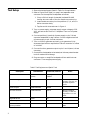
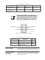
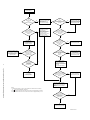
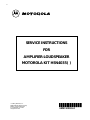
SERVICE INSTRUCTIONS FOR AMPLIFIER-LOUDSPEAKER MOTOROLA KIT HSN4035( ) 1998 by Motorola, Inc. Radio Network Solutions Group 8000 W. Sunrise Boulevard Ft. Lauderdale, FL 33322 All rights reserved. *6881109C65* 68P81109C65-O Table of Contents List of Figures . . . . . . . . . . . . . . . . . . . . . . . . . . . . . . . . . . . . . . . . . . . . . . . . . . . . . . . . . . . . ii List of Tables. . . . . . . . . . . . . . . . . . . . . . . . . . . . . . . . . . . . . . . . . . . . . . . . . . . . . . . . . . . . . iii List of Effective Pages . . . . . . . . . . . . . . . . . . . . . . . . . . . . . . . . . . . . . . . . . . . . . . . . . . . . . iv Safety Summary . . . . . . . . . . . . . . . . . . . . . . . . . . . . . . . . . . . . . . . . . . . . . . . . . . . . . . . . . . . v Introduction . . . . . . . . . . . . . . . . . . . . . . . . . . . . . . . . . . . . . . . . . . . . . . . . . . . . . . . . . . . . . . 1 Reference Publications . . . . . . . . . . . . . . . . . . . . . . . . . . . . . . . . . . . . . . . . . . . . . . . . . . . . . 1 Test Setup . . . . . . . . . . . . . . . . . . . . . . . . . . . . . . . . . . . . . . . . . . . . . . . . . . . . . . . . . . . . . . . . 2 Test Procedure . . . . . . . . . . . . . . . . . . . . . . . . . . . . . . . . . . . . . . . . . . . . . . . . . . . . . . . . . . . . 3 Troubleshooting Procedures . . . . . . . . . . . . . . . . . . . . . . . . . . . . . . . . . . . . . . . . . . . . . . . . . 3 Repair Procedures . . . . . . . . . . . . . . . . . . . . . . . . . . . . . . . . . . . . . . . . . . . . . . . . . . . . . . . . . 5 Initial Disassembly . . . . . . . . . . . . . . . . . . . . . . . . . . . . . . . . . . . . . . . . . . . . . . . . . . . . . . . . . 5 Replacing Speaker. . . . . . . . . . . . . . . . . . . . . . . . . . . . . . . . . . . . . . . . . . . . . . . . . . . . . . . . . . 6 Replacing Printed Circuit Board . . . . . . . . . . . . . . . . . . . . . . . . . . . . . . . . . . . . . . . . . . . . . . 6 Replacing Volume Potentiometer . . . . . . . . . . . . . . . . . . . . . . . . . . . . . . . . . . . . . . . . . . . . 10 Replacing 9-Foot Cable. . . . . . . . . . . . . . . . . . . . . . . . . . . . . . . . . . . . . . . . . . . . . . . . . . . . . 13 Final Reassembly . . . . . . . . . . . . . . . . . . . . . . . . . . . . . . . . . . . . . . . . . . . . . . . . . . . . . . . . . 15 Exploded View and Repair Parts List. . . . . . . . . . . . . . . . . . . . . . . . . . . . . . . . . . . . . . . . . 17 i List of Figures Figure 1. Test Connector Schematic/Wiring Diagram. . . . . . . . . . . . . . . . . . . . . . . . . . . . . . . . . . . . . . 3 Figure 2. Amplifier-Loudspeaker Test and Troubleshooting Procedures . . . . . . . . . . . . . . . . . . . . . . . 4 Figure 3. Separating Front and Rear Housings . . . . . . . . . . . . . . . . . . . . . . . . . . . . . . . . . . . . . . . . . . . 5 Figure 4. PCB Connections to External Components . . . . . . . . . . . . . . . . . . . . . . . . . . . . . . . . . . . . . 8 Figure 5. Removing and Installing PCB . . . . . . . . . . . . . . . . . . . . . . . . . . . . . . . . . . . . . . . . . . . . . . . . 9 Figure 6. Removing Volume Potentiometer . . . . . . . . . . . . . . . . . . . . . . . . . . . . . . . . . . . . . . . . . . . . 11 Figure 7. Preparing New Volume Potentiometer . . . . . . . . . . . . . . . . . . . . . . . . . . . . . . . . . . . . . . . . 12 Figure 8. Connecting Leads to New Volume Potentiometer . . . . . . . . . . . . . . . . . . . . . . . . . . . . . . . 12 Figure 9. Removing and Installing 9-Foot Cable . . . . . . . . . . . . . . . . . . . . . . . . . . . . . . . . . . . . . . . . 14 Figure 10. Installing 9-Foot Cable in Strain Relief. . . . . . . . . . . . . . . . . . . . . . . . . . . . . . . . . . . . . . . . 15 Figure 11. Final Reassembly of Amplifier-Loudspeaker . . . . . . . . . . . . . . . . . . . . . . . . . . . . . . . . . . . . 16 Figure 12. Amplifier-Loudspeaker, Motorola Kit HSN4035( ), Exploded View . . . . . . . . . . . . . . . . . 17 ii List of Tables Table 1. Test Equipment and Special Tools . . . . . . . . . . . . . . . . . . . . . . . . . . . . . . . . . . . . . . . . . . . . . . 2 Table 2. Test Connector Components . . . . . . . . . . . . . . . . . . . . . . . . . . . . . . . . . . . . . . . . . . . . . . . . . 3 Table 3. Repair Parts Required for Speaker Replacement . . . . . . . . . . . . . . . . . . . . . . . . . . . . . . . . . . . 6 Table 4. Repair Parts Required for Printed Circuit Board Replacement . . . . . . . . . . . . . . . . . . . . . . . . 6 Table 5. Printed Circuit Board Connections . . . . . . . . . . . . . . . . . . . . . . . . . . . . . . . . . . . . . . . . . . . . 7 Table 6. Repair Parts Required for Volume Potentiometer Replacement. . . . . . . . . . . . . . . . . . . . . . 10 Table 7. Repair Parts Required for 9-Foot Cable Replacement . . . . . . . . . . . . . . . . . . . . . . . . . . . . . . 13 Table 8. 9-Foot Cable Connections to PCB . . . . . . . . . . . . . . . . . . . . . . . . . . . . . . . . . . . . . . . . . . . . 14 Table 9. Repair Parts Required for Final Assembly . . . . . . . . . . . . . . . . . . . . . . . . . . . . . . . . . . . . . . . 15 Table 10. Repair Parts for Amplifier-Loudspeaker Motorola Kit HSN4035( ) . . . . . . . . . . . . . . . . . . . 17 iii LIST OF EFFECTIVE PAGES Service Instructions For Amplifier-Loudspeaker Motorola Kit HSN4035( ) Motorola Publication Number 68P81109C65-O Issue Dates of Original and Revised Pages are: Original:March 1999 The Number of pages in this publication is 33 consisting of the following: Page Number Revision Letter Page Number Revision Letter Front cover O Questionnaire (Front) O Inside front cover (blank) O Questionnaire (Back O Title O Replacement Parts Ordering (Inside back cover) O i through viii O Back cover O 1 through 18 O NOTE: The letter O in the Revision Letter column in the table above denotes an original page. Original pages ARE NOT identified as such in the page footers except for the absence of a change letter and date. iv Safety Summary Exposure to Radio Frequency Energy (National and International Standards and Guidelines) Your Motorola two-way Radio, which generates and radiates radio frequency (RF) electromagnetic energy (EME), is designed to comply with the following national and international standards and guidelines regarding exposure of human beings to radio frequency electromagnetic energy: • Federal Communications Commission Report and Order No. FCC 96-326 (August 1996) • American National Standards Institute (C95-1-1992) • National Council on Radiation Protection and Measurements (NCRP - 1986) • International Commission on Non-Ionizing Radiation Protection (ICNRP - 1986) • European Committee for Electrotechnical Standardization (CENELEC) - Env. 50166 - 1 1995E - Human Exposure to Electromagnetic Fields Low Frequency (0 Hz to 10kHz) - Env. 50166 - 2 1995E - Human Exposure to Electromagnetic Fields High Frequency (10kHz to 300Ghz) - Proceedings of SC211/8 1996 - Safety Considerations for Human Exposure to E.M.Fs from Mobile Telecommunications Equipment (M.T.E.) in the Frequency Range 30MHz - 6GHz (E.M.F - Electromagnetic Fields) To assure optimal radio performance and that human exposure to radio frequency electromagnetic energy is within the guidelines set forth in the above standards, transmit only when people inside and outside the vehicle are at least the minimum distance away from a properly installed, externally-mounted antenna. The table below lists the minimum distance for several different ranges of rated radio power. Rated Power and Distance Rated Power of Vehicle-installed Mobile Two-way Radio Minimum Distance from Transmitting Antenna 7 to 15 Watts 1 Foot (30.5 Centimeters) 16 to 50 Watts 2 Feet (61 Centimeters) More than 50 Watts 3 Feet (91.5 Centimeters) v Mobile Antenna Installation Install the vehicle antenna external to the vehicle and in accordance with: • The requirements of the antenna manufacturer/supplier • Instructions in the Radio Installation Manual Control Station Operation Note Airbag Warning When radio equipment is used to operate as a control station, it is important that the antenna be installed outside the building and away from places where people may be in close proximity. Refer to Table 1 on page 2 for rated power and minimum distance values for transmitting antennas. VEHICLES EQUIPPED WITH AIR BAGS An air bag inflates with great force. DO NOT place objects, including communications equipment, in the area over the air bag or in the air bag deployment area. If the communications equipment is installed improperly and the air bag inflates, this can cause serious injury. Installation of vehicle communication equipment should be performed by a professional installer/technician qualified in the requirements for such installations. An air bag’s size, shape and deployment area can vary by vehicle make, model and front compartment configuration (e.g., bench seat vs. bucket seats). Contact the vehicle manufacturer’s corporate headquarters, if necessary, for specific air bag information for the vehicle make, model and front compartment configuration involved in your communication equipment installation. LP Gas Warning It is mandatory that radios installed in vehicles fuelled by liquefied petroleum gas conform to the National Fire Protection Association standard NFPA 58, which applies to vehicles with a liquid propane (LP) gas container in the trunk or other sealed off space within the interior of the vehicle. The NFPA58 requires the following: • Any space containing radio equipment shall be isolated by a seal from the space in which the LP gas container and its fittings are located. • Removable (outside) filling connections shall be used. • The container space shall be vented to the outside. vi Anti-Lock Braking System (ABS) and Anti-Skid Braking System Precautions ! WARNING Disruption of the anti-skid/anti-lock braking system by the radio transmitter may result in unexpected vehicle motion. Motorola recommends the following radio installation precautions and vehicle braking system test procedures to ensure that the radio, when transmitting, does not interfere with operation of the vehicle braking system. Installation Precautions 1. Always provide as much distance as possible between braking modulator unit and radio, and between braking modulator unit and radio antenna and associated antenna transmission line. Before installing radio, determine location of braking modulator unit in vehicle. Depending on make and model of vehicle, braking modulator unit may be located in trunk, under dashboard, in engine compartment, or in some other cargo area. If you cannot determine location of braking modulator unit, refer to vehicle service manual or contact a dealer for the particular make of vehicle. 2. If braking modulator unit is located on left side of the vehicle, install radio on right side of vehicle, and conversely. 3. Route all radio wiring including antenna transmission line as far away as possible from braking modulator unit and associated braking system wiring. 4. Never activate radio transmitter while vehicle is in motion and vehicle trunk lid is open. Braking System Tests The following procedure checks for the most common types of interference that may be caused to vehicle braking system by a radio transmitter. 1. Run vehicle engine at idle speed and set vehicle transmission selector to PARK. Release brake pedal completely and key radio transmitter. Verify that there are no unusual effects (visual or audible) to vehicle lights or other electrical equipment and accessories while microphone is NOT being spoken into. 2. Repeat step 1. except do so while microphone IS being spoken into. 3. Press vehicle brake pedal slightly just enough to light vehicle brake light(s). Then repeat step 1. and step 2. 4. Press the vehicle brake pedal firmly and repeat step 1. and step 2. vii 5. Ensure that there is a minimum of two vehicle lengths between front of vehicle and any object in vehicle’s forward path. Then, set vehicle transmission selector to DRIVE. Press brake pedal just far enough to stop vehicle motion completely. Key radio transmitter. Verify that vehicle does not start to move while microphone is NOT being spoken into. 6. Repeat step 5. except do so while microphone IS being spoken into. 7. Release brake pedal completely and accelerate vehicle to a speed between 15 and 25 miles/25 and 40 kilometers per hour. Ensure that a minimum of two vehicle lengths is maintained between front of vehicle and any object in vehicle’s forward path. Have another person key radio transmitter and verify that vehicle can be braked normally to a moderate stop while microphone is NOT being spoken into. 8. Repeat step 7. except do so while microphone IS being spoken into. 9. Release brake pedal completely and accelerate vehicle to a speed of 20 miles/30 kilometers per hour. Ensure that a minimum of two vehicle lengths is maintained between front of vehicle and any object in vehicle’s forward path. Have another person key radio transmitter and verify that vehicle can be braked properly to a sudden (panic) stop while microphone is NOT being spoken into. 10. Repeat step 9. except do so while microphone IS being spoken into. 11. Repeat step 9. and step 10. except use a vehicle speed of 30 miles/ 50 kilometers per hour. POTENTIALLY EXPLOSIVE ATMOSPHERES Turn off your two-way radio when you are in any area with a potentially explosive atmosphere, unless it is a radio type especially qualified for use in such areas (for example, Factory Mutual Approved). Sparks in a potentially explosive atmosphere can cause an explosion or fire resulting in bodily injury or even death. Areas with potentially explosive atmospheres include fueling areas such as: below decks on boats; fuel or chemical transfer or storage facilities; areas where the air contains chemicals or particles, such as grain, dust or metal powders; and any other area where you would normally be advised to turn off your vehicle engine. Areas with potentially explosive atmospheres are often but not always posted. To avoid possible interference with blasting operations, turn off your radio when you are near electrical blasting caps, in a blasting area, or in areas posted: “Turn off two-way radio”. Obey all signs and instructions. viii Introduction Note The empty parentheses at the end of the kit numbers used throughout this publication stand for the alphabetical character (A, B, etc.) that denotes the revision level of the kit. The revision levels of the kits may change from time to time without affecting the validity of these service instructions. This publication provides field level troubleshooting and repair instructions for Amplifier-Loudspeaker Motorola Kit HSN4035. The Amplifier-loudspeaker is a component of the Dual Control Head configuration of the MCS 2000 Mobile Radio. Troubleshooting and repair of the Amplifier-Loudspeaker are limited to localizing and repairing a fault to one of the following: • • • • Volume control potentiometer and its associated wiring Loudspeaker and its associated wiring Circuit card assembly (PCB) and its associated wiring 9-Foot (Power and signal) Cable Provided in this publication for the Amplifier-Loudspeaker are the following procedures in the order listed: • • • • • Reference Publications Test setup Test and Troubleshooting Disassembly Repair Reassembly Motorola Publication 68P81088C64 - Operating Instructions Manual Addendum for Motorola MCS 2000 Dual Control Head Radio Motorola Publication 68P81109C63 - Installation Instructions for Motorola MCS 2000 Dual Control Head Radio Motorola Publication 68P81109C64 - Retrofit Instructions for Motorola MCS 2000 Radio, Single Control Head to Dual Control Head Conversion Motorola Publication 68P02058U20 - GM 900, MC 900, GM 1200, MCX 1200, GM 2000, MCS 2000, MC 2100 Mobile Radios; Installation Instructions; All Frequencies 1 Test Setup 1. Secure the test equipment listed in Table 1 or its equivalents. 2. Refer to Figure 1 and Table 2 on page 3 and assemble a test connector for the amplifie5-loudspeaker as follows: 1. Crimp a 24-inch length of stranded insulated 18 AWG hookup wire onto each of the four female connector pins. 2. Insert female connector pins into positions 1, 2, 4, and 5 in Molex connector body. 3. Tag free end of wires as shown in Figure 1. 3. Turn on power supply, set power supply output voltage to 13.8 VDC, and set current limit to 1.5 Amperes. Then turn off power supply. 4. Connect positive (+) terminal of power supply to pin 5 of test connector assembled in step 2 above. Connect negative terminal of power supply to pin 4 of test connector. 5. Turn on function generator and set it up to generate a 1-kHz sinewave signal with an amplitude of 230-mV rms and a DC offset of +4.4 Vdc. 6. Connect function generator output to pins 1 and 4 (return) of test connector. 7. On amplifier-loudspeaker to be tested, set Volume potentiometer knob to mechanical midrange. 8. Plug connector on amplifier-loudspeaker 9-foot cable into test connector. Then energize power supply. Table 1 Test Equipment and Special Tools Description 2 Manufacturer Model No./Part No. Test Connector Fabricated at Test Facility See Figure 1 and Table 2 Below DC Power Supply Hewlett Packard 6200 Audio Analyzer Hewlett Packard 8903B Function Generator Hewlett Packard 3311A Digital Multimeter Fluke 27 Oscilloscope Tektronix TDS 544A or 2430A Resistor, Fixed, 4-Ohms (+/- 20 percent) 20 Watts Dale H25, 4-Ohms Notes Must be capable of providing 13.8-Vdc, 2.0 Amperes regulated power. Must be capable of providing a 1-kHz test signal with a +4.4-Vdc offset . See note at end of this table Table 1 Test Equipment and Special Tools Description Manufacturer Model No./Part No. Roto-Torq Adjustable Torque Screwdriver Motorola Kit RSX-4043A Spanner Nut Bit for Adjustable Torque Screwdriver Motorola 66-80371B34 Note Notes Motorola Test Box RKN4460( ) can be substituted for the 4-Ohm 20-Watt fixed resistor specified in table 1. When pins 2 and 6 of female connector on back of test box are shorted together and SPKR/LOAD switch on top of test box is set to LOAD, a suitable 4-Ohm 20-Watt resistance is available between the two EXTERNAL LOAD jacks on top of test box. 4 1 5 2 6 3 Audio Input Analog Ground Ground B+ MAEPF-26585-O Figure 1 Test Connector Schematic/Wiring Diagram Table 2 Test Connector Components Motorola Part No. Description Quantity 1584953L01 Molex Connector Body, 6 Pin 1 2984706E06 Molex Connector Pin, Female 4 Not Applicable Hookup Wire, Stranded, Insulated, 18 AWG, 24-Inches Long 4 Test Procedure The test procedure for the amplifier-loudspeaker is presented in the test and troubleshooting procedures pyramid diagram, Figure 2. Troubleshooting Procedures The troubleshooting procedure for the amplifier-loudspeaker are presented in the test and troubleshooting procedures pyramid diagram, Figure 2 on page 4. 3 START TEST Any Sound Output From Amplifier-Loudpeaker? 1. Turn Off Power Supply. 2. Perform Procedure Titled Separating Front and Rear Housings. 3. Turn On Power Supply. No Perform Procedure Titled Replacing 9-Foot Cable. If That Does Not Repair Fault, Perform Procedure Titled Replacing PCB. No Yes Yes Is Sound Output Undistorted and About Normal Listening Volume? Is 13.8Vdc Present Between Terminals TP12 (+) and TP13 (-) on PCB? 1. Turn Off Power Supply. 2. Perform Procedure Titled Separating Front and Rear Housings. 3. Disconnect One Speaker Lead at Speaker End. 4. Connect a 4-Ohm Resistor Between TP10 and TP11 on PCB. 5. Turn On Power Supply. No Is 1-kHz 230mVrms Signal Present Between TP1 and TP2 (Rtn) on PCB? No Yes Yes Is 1-kHz 220mVrms (440mV p-p) Signal Present Between TP7 and TP2 (Rtn) on PCB? Rotate Volume Potentiometer Knob Slowly From Fully Counterclockwise Position to Fully Clockwise Position. No Perform Procedure Titled Replacing PCB. Yes Perform Procedure Titled Replacing Volume Potentiometer, If That Does Not Repair Fault, Perform Procedure Titled Replacing PCB. No Is 1-kHz 180mVrms (320mV p-p) Signal Present Between TP8 and TP2 (Rtn) on PCB? (Note 2) Does Volume Potentiometer Adjust Sound Output Smoothly Over its Entire Range? Yes 4 Is Sound Output Undistorted At All Settings of Volume Potentiometer? No Perform Procedure Titled Replacing Volume Potentiometer. If That Does Not Repair Fault, Perform Procedure Titled Replacing PCB. Yes No 1. Turn Off Power Supply. 2. Disconnect One Speaker Lead at Speaker End. 3. Connect a 4-Ohm Resistor Between TP10 and TP11 on PCB. 4. Turn On Power Supply. Figure 2 Amplifier-Loudspeaker Test and Troubleshooting Procedures Yes Amplifier-Loudspeaker Is In Good Operating Condition. End of Test. Is 1-kHz 3.2Vrms (8.8V p-p) Signal Present Between TP10 and TP11 on PCB (Note 3)? No Perform Procedure Titled Replacing PCB. Yes 1. Connect Distortion Analyzer Between TP10 and TP11 on PCB. 2. Rotate Volume Potentiometer Knob Slowly Over its Entrire Range. Notes: 1. All specified voltage, current, and resistance values have a tolerance of 10% unless indicated otherwise. 2. Signal between TP8 and TP2 has a DC offset of approximately +160mV. 3. Signal between TP10 and TP11 has a DC offset of approximately +6.1V. Is Harmonic Distortion of Signal Between TP10 and TP11 5% or Less for All Settings of Volume Pot.? No Yes Perform Procedure Titled Replacing Speaker MAEPF-26581-O Repair Procedures Initial Disassembly 1. Refer to Figure 3. Push tips of two identical or similar small flat blade screwdrivers into opening between front and rear housings. 2. Push both screwdriver blades simultaneously away from speaker to pop up and release front housing from rear housing. ! Caution When performing step 3, be very careful to avoid damaging loudspeaker cone, which faces upward directly below front cover. 3. Pull front housing off of rear housing carefully, which will expose speaker cone. 4. Grasp speaker at its edges and lift it up and out of rear housing. Leave wires (black Zipcord) connected to PCB and set speaker face down next to right side of rear housing. Dimple Front Housing Rear Housing Gasket MAEPF-26667-O Figure 3 Separating Front and Rear Housings 5 Replacing Speaker Repair Parts Required The repair parts required for replacing the speaker in the AmplifierLoudspeaker are listed in Table 3. Table 3 Repair Parts Required for Speaker Replacement Motorola Part No. Quantity Required Description 5085891B01 Speaker, 5-inch 1 3285203C01 Gasket (Required for Final Assembly of Amplifier-Loudspeaker) 1 1110027B23 Gasket Lubricant (Required for Final Assembly of Amplifier-Loudspeaker) As Required Replacement Procedure 1. Perform procedure titled Initial Disassembly on page 5. Note In step 2, disconnect speaker wires from speaker end only (i.e., do not disconnect speaker wires from PCB). 2. Refer to Figure 4 on page 8. Using a soldering iron, disconnect black (Zipcord) wires at speaker end of wires that connect speaker to PCB. Discard old speaker. 3. Using a soldering iron, connect wires disconnected in step 2 to terminals of new speaker, Motorola part no. 5085891B01. Either wire can be connected to either speaker terminal. 4. Perform procedure titled Final Reassembly on page 15. Replacing Printed Circuit Board Repair Parts Required The repair parts required for replacing the printed circuit board (PCB) in the Amplifier-Loudspeaker are listed in Table 4. Table 4 Repair Parts Required for Printed Circuit Board Replacement Motorola Part No. 6 Quantity Required Description 0105956V07 Printed Circuit Board 1 1110022A55 Thermal Grease As Required Table 4 Repair Parts Required for Printed Circuit Board Replacement Motorola Part No. Quantity Required Description 3285203C01 Gasket (Required for Final Assembly of Amplifier-Loudspeaker) 1 1110027B23 Gasket Lubricant (Required for Final Assembly of Amplifier-Loudspeaker) As Required Replacement Procedure 1. Perform procedure titled Initial Disassembly on page 5. Note In step 2, do not discard any of the wires after they are disconnected. All wires are reused. 2.Refer to Table 5 and Figure 4 on page 8. Using a soldering iron, disconnect the following 11 wires at PCB. 1. The six 9-foot cable wires (bare, black, white/black, blue, red, white) from TP1 through TP6 2. The three Volume potentiometer leads (blue, gray, white) from TP7 through TP9 3. The two speaker wires (black Zipcord conductors) from TP10 and TP11 3. Refer to Figure 5 on page 9. Remove the four M3x0.5 machine screws that attach PCB to inside of rear housing. Save screws for use in step 6. 4. Carefully lift PCB straight up and out of rear housing. 5. Apply a thin layer of thermal compound, Motorola part no. 1110022A55, to shaded area shown in Figure 5. 6. Mount new PCB to inside of rear housing using the four M3x0.5 machine screws removed in step 3. Torque screws to 7.5 inch pounds (0.848 Newton meter). 7. Refer to Table 5 and Figure 4 on page 8. Using a soldering iron, reconnect the 11 wires to the new PCB. 8. Perform procedure titled Final Reassembly on page 15. Table 5 Printed Circuit Board Connections Wire Color From/To Component PCB Terminal Number Blue 9-Foot Cable TP1 Black 9-Foot Cable TP2 White/Black 9-Foot Cable TP3 Bare 9-Foot Cable TP4 7 Table 5 Printed Circuit Board Connections Wire Color From/To Component PCB Terminal Number Red 9-Foot Cable TP5 White 9-Foot Cable TP6 Blue Volume Pot. Counterwise End) TP7 Gray Volume Pot. Center (Arm) TP8 White Volume Pot. Clockwise End TP9 Black Speaker (Either Terminal) TP10 Black Speaker (Either Terminal) TP11 TP10 TP11 TP7 TP8 TP9 TP4 TP6 TP3 TP5 TP2 TP1 MAEPF-26669 -O Figure 4 PCB Connections to External Components 8 Thermal Grease Location (Shaded Area) Circuit Board Rear Housing MAEPF-26577-O Figure 5 Removing and Installing PCB 9 Replacing Volume Potentiometer Repair Parts Required The repair parts required for replacing the Volume Potentiometer in the Amplifier-Loudspeaker are listed in Table 6. Table 6 Repair Parts Required for Volume Potentiometer Replacement Motorola Part No. Quantity Required Description 1805629V05 Volume Potentiometer 1 3205082E01 O-Ring, Volume Potentiometer (The smaller of the two O rings) 1 0402838X01 Wave Washer 1 0205609X01 Spanner Nut 1 3205082E48 O-Ring, Spanner Nut (The larger of the two O-rings) 1 3285203C01 Gasket 1 1110027B23 Gasket Lubricant 1 3285968B01 Gasket (Required for Final Assembly of Amplifier-Loudspeaker) 1 1110027B23 Gasket Lubricant (Required for Final Assembly of Amplifier-Loudspeaker) As Required Alpha FIT-221 -1/16 Hookup Wire, 24 AWG, Stranded As Required Alpha UL1007 (Grey, Blue, and White) Heat Shrinkable Sleeving, 0.062 in. I.D., 0.375-in.long As Required Replacement Procedure 1. Perform procedure titled Initial Disassembly on page 5. 2. Using soldering iron, disconnect the three wires (blue, gray, white) from the three terminals of Volume potentiometer. 3. Refer to Figure 6 on page 11. Pull knob straight off of Volume potentiometer shaft. 4. Using an adjustable torque screwdriver, Motorola kit RSX4043( ) with a spanner wrench tip, Motorola part no. 6680371B03, remove spanner nut that retains Volume potentiometer in rear housing. 5. Grasp Volume potentiometer from back and pull it carefully straight back and out of rear housing. Discard wave washer, which falls off potentiometer shaft when potentiometer is pulled out of rear housing. 10 6. Refer to Figure 7 on page 12. Carefully slide a new O-ring, Motorola part no. 3205082E01, over shaft and threaded bushing until it is flat on face of new potentiometer. 7. Refer to Figure 6. Insert new potentiometer into hole in rear housing. Be certain than key engages into slot in rear housing. 8. Place a new wave washer, Motorola Part No. 3205082E48, over threaded shaft of new potentiometer. 9. Refer to Figure 7 on page 12. Install a new O-ring. Motorola Part No. 3205082E48, on a new spanner nut, Motorola Part No. 0205609X01. 10.Thread spanner nut onto threaded shaft of new potentiometer until it is hand tight. 11.Using an adjustable torque screwdriver, Motorola kit RSX4043( ) with a spanner wrench tip, Motorola part no. 6680371B03, tighten spanner nut to a torque of 8-inch-pounds (0.91 Newton Meter). 12.Using solder iron, connect wires to new Volume potentiometer as shown in Figure 8 on page 12. 13.Perform procedure titled Final Reassembly on page 15. Volume Potentiometer Key Wave Washer Volume Knob Spanner Nut MAEPF-26573-O Figure 6 Removing Volume Potentiometer 11 Volume Potentiometer Base of Threaded Shaft Spanner Nut Groove Volume Potentiometer O-ring Motorola P/N 3205082E01 Spanner Nut O-ring Motorola P/N 3205082E48 MAEPF-26570-O Figure 7 Preparing New Volume Potentiometer Volume Potentiometer Volume Potentiometer Terminals Volume Potentiometer Terminals Heat Shrink Sleeve (3), 1/16 in. diameter x 0.375 in. long 24 AWG Wire, 2.5 in. long Blue Gray White MAEPF-26571-O Figure 8 Connecting Leads to New Volume Potentiometer 12 Replacing 9-Foot Cable Repair Parts Required The repair parts required for replacing the 9-Foot Cable in the Amplifier-Loudspeaker are listed in Table 7. Table 7 Repair Parts Required for 9-Foot Cable Replacement Motorola Part No. Description Quantity Required 3085853B01 9-Foot Cable 1 4285841A02 Strain Relief 1 3285203C01 Gasket (Required for Final Assembly of Amplifier-Loudspeaker) 1 1110027B23 Gasket Lubricant (Required for Final Assembly of Amplifier-Loudspeaker) As Required Replacement Procedure 1. Perform procedure titled Initial Disassembly on page 5. 2. Refer to Figure 4 on page 8. Using soldering iron, disconnect the seven 9-foot cable wires (blue, black, white/black, bare, red, white, blue) from TP1 through TP6 on PCB. 3. Refer to Figure 9 on page 14. Remove locknut from strain relief on 9-foot cable. Then remove strain relief (with 9-foot cable still clamped in it) from rear housing and discard it. 4. Refer to Figure 10 on page 15. Insert unwired end of new 9-foot cable, Motorola part no. 3085853B01, into new strain relief, Motorola part no. 428541A02, so that cable jacket protrudes 0.25inch or slightly less past inside edge of strain relief. 5. Using a torque wrench,torque clampnut on strain relief to 12-inch-pounds (1.36 Newton Meters). 6. Hold strain relief in one hand and pull 9-foot cable with other hand to verify that 9-foot cable is clamped tightly in strain relief. 7. Refer to figure 9 on page 14. Route unwired end of new 9-foot cable into rear housing until strain relief is flush with outside of rear housing. 8. Hand thread locknut onto strain relief and tighten it hand tight. Then, using a torque wrench, torque locknut to 12 inch-pounds (1.36 Newton meters). 9. Refer to Table 4 on page 6. Using a soldering iron, cut to length, strip, tin, and solder the leads of the new 9-foot cable to PCB. 10.Perform procedure titled Final Reassembly on page 15. 13 Table 8 9-Foot Cable Connections to PCB Wire Color PCB Terminal Number Blue TP1 Black TP2 White/Black TP3 Bare TP4 Red TP5 White TP6 Strain Relief Locknut Rear Housing Surface must be flush with exterior surface of rear housing Strain Relief 9-Foot Cable MAEPF-26575-O Figure 9 Removing and Installing 9-Foot Cable 14 Cable Jacket Must Not Protude Further than 0.25 in. Beyond Strain Relief 9 Foot Cable Wire Leads Strain Relief 9 Foot Cable 9 Foot Cable MAEPF-26574-O Figure 10 Installing 9-Foot Cable In Strain Relief Final Reassembly Final reassembly consists of replacing the gasket and then installing the front housing of the amplifier-loudspeaker onto the rear housing. Repair Parts for Final Reassembly The repair parts required for final reassembly of the AmplifierLoudspeaker are listed in table 9. Table 9 Repair Parts Required for Final Reassembly Motorola Part No. Description Quantity Required 3285203C01 Gasket (Required for Final Assembly of Amplifier-Loudspeaker) 1 1110027B23 Gasket Lubricant (Required for Final Assembly of Amplifier-Loudspeaker) As Required 15 Front Housing See Detail A Front Edge of Gasket Delta Gasket Back Edge of Gasket Detail A MAEPF-26578-O Figure 11 Final Reassembly of Amplifier-Loudspeaker Reassembly Procedure 1. Place speaker back into rear housing with terminals on speaker oriented over TP10 and TP11 on PCB. Be certain that speaker wires Zipcord) fold forward towards center of PCB and then back and are not pinched between back of speaker and PCB. 2. Refer to Figure 11. Remove and discard gasket from front housing. 3. Lubricate new gasket Motorola part no. 3285203C01, using gasket lubricant Motorola part no. 1110027B23. 4. Place new gasket into front housing being certain that gasket is oriented as shown in Figure 11. 5. Snap front housing onto rear housing. 6. Inspect entire recess area around the housing to verify that gasket is not pinched between front and rear housings. If gasket is not pinched, reassembly is complete. If gasket is pinched, proceed to step 7. 7. perform procedure titled Initial Disassembly on page 5. Then repeat steps 2 through 6 above. 16 Exploded View and Repair Parts List Figure 12 is an exploded view, which illustrates and locates all repair parts for the Amplifier-Loudspeaker, Motorola kit HSN4035( ). Table 8 lists all repair parts for the Amplifier-Loudspeaker and provides Motorola part numbers for all repair parts. Table 10 crossreferences the repair parts to the parts illustrated on Figure 12. 13 5 4 3 1 12 6 4 7 8 9 10 11 2 MAEPF-26569-O Figure 12 Amplifier-Loudspeaker, Motorola Kit HSN4035( ) Exploded View Table 10 Repair Parts for Amplifier-Loudspeaker Motorola Kit HSN4035( ) Reference No. on Figure 12 Descriprion Motorola Part No. 1 Gasket 3285203C01 2 Speaker 5085891B01 3 Printed Circuit Board 0105956V07 4 Locknut, Strain Relief 4285841A02 5 9-Foot Cable 3085853B01 6 Wave Washer, Volume Pot. 0402838X01 7 Spanner Nut, Volume Pot. 0205609X01 17 Table 10 Repair Parts for Amplifier-Loudspeaker Motorola Kit HSN4035( ) Reference No. on Figure 12 18 Descriprion Motorola Part No. 8 O-Ring, Volume Pot. Spanner Nut 3205082E48 9 Knob, Volume Pot. 3604250J01 10 Volume Pot. 1805629V05 11 O-Ring, Volume Pot. Shaft 3205082E01 12 Lubricant, Gasket 1110027B23 13 Thermal Compound, PCB Heatsink 1110022A55 We believe that reports from users provide valuable information for producing quality manuals. By taking a few moments to answer the following questions as they relate to this specific manual, you can take an active role in the continuing effort to ensure that our manuals contain the most accurate and complete information of benefit to you. Thank you for your cooperation. In reference to Manual Number: 68P81109C65-O Not Covered in This Manual Size Too Small Size Adequate Confusing Clear Incorrect Correct Incomplete MCS 2000™ Mobile Radio Amplifier-Loudspeaker 1. Please check all the appropriate boxes: Complete Cut along dotted line SERVICE MANUAL QUESTIONNAIRE Disassembly Procedures Alignment Procedures Exploded Views Schematic Diagrams Circuit Board Details Electrical Parts Lists Exploded View Parts List 2. How would you rate the overall organization of this manual? excellent very good good fair poor 3. Did this Service manual provide you with the information necessary to service and maintain the specific equipment? very much so generally yes to some extent no 4. How do you rate this particular Service Manual? excellent very good good fair poor 5. We would appreciate any corrections or recommendations for improving this manual. Please include the specific page number(s) of the diagram or procedure in question. a. Disassembly Procedures:(Page No. __________ ) b. Alignment Procedures:(Page No. __________ ) c. Exploded Views:(Page No. __________ ) NO POSTAGE NECESSARY IF MAILED IN THE UNITED STATES BUSINESS REPLY MAIL FIRST CLASS MAIL PERMIT NO 9040 FT. LAUDERDALE, FL POSTAGE WILL BE PAID BY ADDRESSEE Attention: Media and Communication 8000 W. Sunrise Boulevard Ft. Lauderdale, FL 33322 FOLD (Continued) FOLD Please specify the page number along with any corrections or recommendations for improvement. d. Schematic Diagrams: (Page No. __________ ) e. Component Location Details: (Page No. __________ ) f. Electrical Parts List: (Page No. __________ ) g. Exploded View Parts List: (Page No. __________ ) 6. General comments/suggestions: Name:............................................................................................................................................ Company: ...................................................................................................................................... Customer COSC MSS FTR Other Address: ........................................................................................................................................ City/State/Zip:................................................................................................................................ Phone Number (Please include Area Code): ................................................................................ PLEASE USE TAPE TO SEAL POSTAL REGULATIONS PROHIBIT USE OF STAPLES REPLACEMENT PARTS ORDERING ORDERING INFORMATION When ordering replacement parts or equipment information, the complete identification number should be included. This applies to all components, kits, and chassis. If the component part number is not known, the order should include the number of the chassis or kit of which it is a part, and sufficient description of the desired component to identify it. Crystal and channel element orders should specify the crystal or channel element type number, crystal and carrier frequency, and the model number in which the part is used. MAIL ORDERS Send written orders to the following addresses: Replacement Parts/ Test Equipment/Manuals/ Crystal Service Items: Federal Government Orders: International Orders: Motorola Inc. United States and Canada Accessories and Aftermarket Division Attention: Order Processing 1313 E. Algonquin Road Schaumburg, IL 60196 Motorola Inc. United States and Canada Accessories and Aftermarket Division Attention: Order Processing 7230 Parkway Drive Landover, MD 21076 Motorola Inc. United States and Canada Accessories and Aftermarket Division Attention: International Order Processing 1313 E. Algonquin Road Schaumburg, IL 60196 TELEPHONE ORDERS United States and Canada Accessories and Aftermarket Division: Call: 1-800-422-4210 1-800-826-1913 (For Federal Government Orders) 1-847-538-8023 (International Orders) Servicers Training (VHS Video Tapes): Call: 847-576-2828 FAX ORDERS United States and Canada Accessories and Aftermarket Division: FAX: 847-538-8198 (Domestic) 847-576-3023 (International) Parts ID: 847-538-8194 PARTS CUSTOMER SERVICE United States and Canada Accessories and Aftermarket Division: Call: 1-800-422-4210 Parts Identification: Call: 847-538-0021 Federal Government Orders: FAX: 410-712-4991 International: 410-712-6200 PRODUCT CUSTOMER SERVICE Customer Response Center (Sales and Service Assistance): Call: 1-800-247-2346 FAX: 1-800-232-9272 TEPF-9679-T 1 Service Instructions Amplifier-Loudspeaker Motorola Kit HSN4035( ) Motorola Publication 68P81109C65-O *6881109C65-O* 6881109C65-O