1
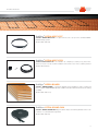
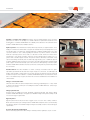
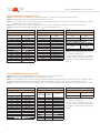
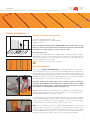
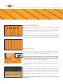
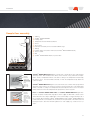
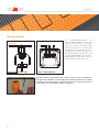
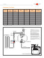
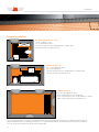
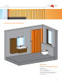
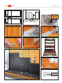
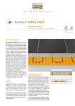
Schlüter®-DITRA-HEAT-E Under tile and stone heating with Schlüter®-DITRA technology Installation Manual Installation Helpline: 01530 813396 Schlüter®-DITRA-HEAT-E Schlüter®-DITRA-HEAT-E is a under tile and stone heating system for floors and walls that quickly creates comfortably warm environment. The heating cables of Schlüter®-DITRA-HEAT-E are installed in the uncoupling mat corresponding to areas that are to be heated. Due to the flexible control of temperatures and heating times provided by the Schlüter touchscreen thermostat, you can use Schlüter®-DITRA-HEAT-E to create warmth whenever and wherever you choose. Contents Advantages Product check list 03 04 Installation Thermostat instructions 06 11 pliance with all applicable safety regulations. To maintain compliance with Protection Class II, user access to the rear of the device must be prevented... This device, is used to control the temperature only l in dry r rooms, under normal environmental conditions. This electronic device conforms to EN 60730, It is an “independently l mounted control” and works according to operating principle 1C. Heating cable test * For current > 14 A do not loop the N N-wire wire through the controller, r use a separate terminal. Digital set up details7 Wiring Diagram / Dimensions Saturday and Sunday Events Time Temperature T Te mperature °C 1 8:00 28,0 2 3 4 5 10:00 12:00 14:00 19:00 18,0 28,0 18,0 28,0 6 22:00 15,0 28 27 26 25 24 23 3 Use 22 21 12 The electronic Floor Temperature Controller can be used to control the floor temperature in conjunction with: • Direct floor heating • Floor temperature conditioning systems 20 19 18 17 15 14 6:00 h • • • • • • One line text display for simplified operation Back light Real time clock (setting of year, month, day, time) Automatic Summer- Winter time change over Max 9 events per day (each day independently) Pre set and adjustable programs 13 Mon - Fri Sat - Sun 16 4 Features 8:00 h 10:00 h 12:00 h 14:00 h 16:00 h 18:00 h 20:00 h Monday to Friday Events 1 2 Time 11:00 13:00 Temperature °C 28,0 18,0 3 22:00 15,0 1.)) Testing est g and a d start sta t up log, og, Sc Schlüter üte ®-DITRA-HEAT-E Sample installation Testing and start up log Project: Date of installation: Certified electrician: Date of start up: 2.) Heating cable Schlüter®-DITRA-HEAT-E-HK 14 2 22:00 h Program 3 Total resistance (Ohm) before installation after installation 18 Insulatio Manufacture No. before installa Schlüter®-DITRA-HEAT-E Advantages of Schlüter®-DITRA-HEAT-E: Pleasant room climate Based on gentle radiated heat and maintaining the natural humidity of a room. Precise control Thanks to the digital thermostats, your preferred temperatures can be set easily and precisely in every room. The new controls for Schlüter®-DITRA-HEAT also allow for controlling the room temperature. Cost efficient to buy, install, maintain, and operate. Durable and maintenance free Absence of wear and tear makes the system virtually maintenance free with a long life expectancy. Easy to retrofit Quick and easy to install, low assembly height ideal for refurbishment. (uncoupling mat incl. heating cable just 5.5 mm) Simple to install The heating wires are installed in the uncoupling mat, with tiles adhered in the thin set tile adhesive directly above them. There is no need to trowel over unheated areas as in the case of conventional heating mats. Suitable for allergy sufferers The space is heated with gentle radiated heat so that no allergens are stirred up. Fast heat-up response The electrical heating wires warm up ceramic tile and natural stone coverings much faster than, for instance, heating systems based on water tubing. Prevents mould growth Heating and fast drying of walls in shower areas helps prevent mould growth. Invisible Beautiful design with ceramic tiles or elegant natural stone instead of bulky heaters. Certified system components Schlüter®-DITRA-HEAT uncoupling and bonded waterproofing (CE Marked) assembly with national technical approval in Germany and the VDE-certified heating cable Schlüter®DITRA-HEAT-E-HK. The use of Schlüter®-DITRA-HEAT with heating cables as floor and wall heating is only permissible for indoor areas. 3 Product check list Schlüter®-DITRA-HEAT-MA Schlüter®-DITRA-HEAT-MA is a polypropylene membrane with a cut back stud structure and an anchoring fleece laminated on the underside. It is a universal substrate for tile coverings, which serves as an uncoupling layer and moisture vapour barrier and is designed for the attachment of the matching heating cables of the system for heating. Available in 0.8m² panels and 12.5 x 1m rolls. (Product data sheet 6.4) Schlüter®-DITRA-HEAT-E-HK Schlüter®-DITRA-HEAT-E-HK is an electrical heating cable with a unilateral connection for installation in the uncoupling mat Schlüter®-DITRA-HEAT-MA. Available in lengths for single zones from 1.1 m² - 10m². (Product data sheet 6.4) Schlüter®-DITRA-HEAT-E-R Schlüter®-DITRA-HEAT-E-R is a digital touchscreen thermostat providing full control of time and temperature for floor and wall heating. Temperature is read by the included floor sensor and an additional facility of the integrated air temperature sensor. The discrete design blends in with conventional switch boxes as it‘s only 5.5 x 5.5 cm in dimension. An additional floor sensor is included in the box. (Product data sheet 6.4) Schlüter®-DITRA-HEAT-E-RS Schlüter®-DITRA-HEAT-E-RS is a digital floor thermostat for the Schlüter®-DITRA-HEAT-E floor heating system. The 230 V version has a removable digital clock for programming the time controlled floor heating system. The thermostat is supplied as a set with remote sensor (4 m), conduit (2.5 m), sensor sleeve and junction box. (Product data sheet 6.4) 4 Product check list Schlüter®-DITRA-HEAT-E-FF Schlüter®-DITRA-HEAT-E-FF is a spare remote sensor (4 m) for the Schlüter®-DITRAHEAT-E heating system. (Product data sheet 6.4) Schlüter®-DITRA-HEAT-E-ZS Schlüter®-DITRA-HEAT-E-ZS is an installation set comprising a conduit (2.5 m), junction box, and sensor sleeve. It can be used if the installation of the remote sensor in the conduit is preferred. (Product data sheet 6.4) Schlüter®-KERDI-BOARD Schlüter®-KERDI-BOARD is a universal substrate for the installation of tiles on walls and floors. Schlüter®-KERDI-BOARD provides additional insulation beneath the electrical heating assembly. (Product data sheet 12.1) Schlüter®-DITRA-SOUND-RSK Schlüter®-DITRA-SOUND-RSK edge insulation strip for around the perimeter of the room to reduce on sound transfer through walls. (Product data sheet 6.3) 5 Installation Before installing our Schlüter®-DITRA-HEAT the following should be observed: Substrates for Schlüter®-DITRA-HEAT: Always check the substrates on which Schlüter®-DITRA-HEAT is to be installed to make sure they are even, rigid, load-bearing, clean and compatible with the materials to be used. Remove all surface components that may weaken the bond. Uneven or sloped areas must be levelled prior to the installation of Schlüter®-DITRA-HEAT. To guarantee the effective heating, thermal insulation (e.g. Schlüter®-KERDI-BOARD) should be included in all installations. Concrete: Concrete is subject to long-term form changes due to curing processes. Additional tensions may result from the deflection of concrete and pre-stressed concrete. Schlüter®-DITRAHEAT uncouples the tensions between concrete and tile covering, which means that tiles can be installed as soon as the concrete reaches a sufficient level of stability. On walls allow at least 6 weeks drying time prior to fixing Schlüter®-DITRA-HEAT mat, ensuring the background is stable, clean and rigid and that it is free from any barriers to adhesion, e.g. plaster droppings, grease, etc. Surfaces to be tiled must be flat and when checked with a 2 metre straight edge, any gap under the straight edge between points of contact with contact with the surface should not exceed 3 mm. Minor irregularities should be pre-smoothed prior to fixing the mat. Cementitious screeds: With Schlüter®-DITRA-HEAT, tiles can be installed on green cementitious screeds as soon as they are ready to bear weight (please note that additional drying time may be required for screed depths over 40 mm). In accordance with the applicable regulations, cementitious screeds must be at least 28 days old and have a residual moisture level below 2 CM% before tiles can be installed. However, floating screeds and heated screeds are particularly prone to curling and cracking, for example because of weight loads and temperature fluctuations. Calcium sulfate screeds: According to the applicable regulations, calcium sulfate screeds (anhydrite screeds) must have a residual moisture level below 0.5 CM% before tiles can be installed. When Schlüter®-DITRA-HEAT is used, the tile covering is ready to be installed as soon as the residual moisture level drops below 2 CM%. If necessary, treat the screed surface in accordance with the codes of practice and manufacturer instructions (sanding, priming). Schlüter®-DITRA-HEAT can be installed with dry-set adhesives or other suitable thin-bed adhesives. Schlüter®-DITRA-HEAT protects the screed against the penetration of moisture at the surface. Calcium sulfate screeds are sensitive to moisture, making it necessary to protect the screed from further moisture. Heated screeds: Schlüter®-DITRA-HEAT may also be installed over heated screeds, with the above material notes to be observed (cement, calcium sulfate). When Schlüter®-DITRAHEAT is used, the covering assembly may be heated up as early as 7 days after completion. Starting from 25 °C, increase the supply temperature by a maximum of 5 °C a day to reach an operating temperature of max. 40 °C. Note: The use of Schlüter®-DITRA-HEAT over heated screeds allows for individual, partial heating that is separate from the central heating system. This makes it feasible to switch off the central heating system during seasonal transition periods. Furthermore, Schlüter®-DITRAHEAT can help cover peak loads. 6 Installation Synthetic coverings and coatings: All surfaces must be weight-bearing and, if necessary, pre-treated, to allow for the bonding of a suitable adhesive for permanent attachment of the bonding fleece of Schlüter®-DITRA-HEAT. The suitability of the adhesive for the substrate and for Schlüter®-DITRA-HEAT must be verified in advance. Plywood panels: These materials are heavily affected by moisture (or large fluctuations in humidity). It is therefore recommended to use plywood materials with special impregnation to prevent the absorption of moisture (e.g. external grade plywood). Where available refer to the codes of practice relevant to each country regarding the selection of products and the construction methods. In principle, panels can be used as a substrate on walls and floors in interior areas. The thickness of the panels should be selected to ensure sufficient impact resistance in conjunction with a suitable support structure. The panels must be sufficiently secured with closely spaced screw fixings. All board joints should be fully supported by joists or additional supports (noggins). Additional supports may prove necessary to provide a rigid and stable substrate. Edge joints of approx. 10 mm must be kept open at the connections with adjoining construction parts. Schlüter®-DITRA-HEAT neutralises the stresses in the tile covering and also prevents the penetration of moisture. Hardwood floors: The direct installation of ceramic coverings over hardwood floors is generally feasible, provided the floorboards have tongue and groove connections, are sufficiently load bearing, and are tightly screwed down. The wooden substrate should have reached a balanced moisture level prior to the installation of Schlüter®-DITRA-HEAT. Experts recommend the installation of an additional layer of plywood. Uneven floors must be levelled before the installation of other materials. Tiling to cement/sand render Finish the surface with a wood float and prevent the surface from rapid drying for 1–2 days. Allow to air dry for at least two weeks prior to installing the Schlüter®-DITRA-HEAT mat. Surface regularity is as per concrete. Tiling to plasterboard Ensure boards are rigidly braced and adequately supported; DO NOT skim plaster, adhere Schlüter®-DITRA-HEAT directly to the paper face. Maximum weight of tiling and assembly should not exceed 32 kg per square metre. Gypsum plaster Gypsum plaster must be dry and at least 4 weeks old, do not use in wet or damp conditions. Brush down the surface prior to fixing Schlüter®-DITRA-HEAT and prime surface as instructed by the adhesive supplier. The maximum weight of tiling and assembly should not exceed 20 kg per square metre. Concrete blockwork and brickwork Allow 6 weeks drying time before direct fixing or rendering. Surface regularity is as per concrete. 7 Schlüter®-DITRA-HEAT-E – Floor heating Pre-installation planning for floors Step 1: Draw floor area onto graph paper removing unheated areas, e.g. bath, shower, sink, toilet and kitchen units etc. Step 2: Calculate heating area with unheated areas removed from calculation. Step 3: Choose heating area from heating cable chart below. The heating cable must be calculated and installed 2 studs (60 mm) from all walls and building elements, e.g. bath, toilet bowl etc. Step 4: Choose total floor area from the uncoupling chart ensure enough uncoupling mat is purchased to cover the whole floor area. Step 5: Select either the standard digital thermostat or a touchscreen digital thermostat. Schlüter®-DITRA-HEAT-MA Schlüter®-DITRA-HEAT-E-HK Schlüter®-DITRA-HEAT-E-RS uncoupling matting required heating cable required at 136 W/m2 thermostat required (standard digital) total floor area in m² 0.90 1.70 2.50 3.30 4.10 4.90 5.70 6.50 7.30 8.10 8.90 9.70 10.50 11.30 – 1.60 – 2.40 – 3.20 – 4.00 – 4.80 – 5.60 – 6.40 – 7.20 – 8.00 – 8.80 – 9.60 – 10.40 – 11.20 – 12.00 Art.-No. heated area in m² DH5 MA DH5 MA DH5 MA DH5 MA DH5 MA DH5 MA DH5 MA DH5 MA DH5 MA DH5 MA DH5 MA DH5 12M DH5 12M DH5 12M 1.1 1.6 2.2 2.7 3.3 3.8 4.4 5.0 5.5 6.6 7.7 8.8 10.0 Art.-No. DH E HK 12 DH E HK 17 DH E HK 23 DH E HK 29 DH E HK 35 DH E HK 41 DH E HK 47 DH E HK 53 DH E HK 59 DH E HK 71 DH E HK 83 DH E HK 95 DH E HK 107 Qty Art.-No. 1 DH E RS 230D/BW ® Schlüter -DITRA-HEAT-E-R thermostat required (touchscreen digital) Qty Art.-No. 1 DH E RT2 / BW Note: For larger areas add the areas together to calculate the requirements. The above charts should be used as a guide only. Full drawings should be created and requirements calculated before selecting the products. Pre-installation planning for walls Step 1: Draw wall area onto graph paper removing unheated areas, e.g. mirrors, wall units etc. Step 2: Calculate heating area with unheated areas removed from calculation. Step 3: Choose heating area from heating cable chart below, determining whether the output needs to be 200 W/m2 (2 studs) or 136 W/m2 (3 studs). The heating cable must be installed 2 studs (60 mm) from all walls and building elements, e. g. door frame, shower screen, windows. Step 4: Choose total floor area from the uncoupling mat chart ensure enough uncoupling mat is purchased to cover the whole area to be heated. Schlüter®-DITRA-HEAT-MA Schlüter®-DITRA-HEAT-E-HK Schlüter®-DITRA-HEAT-E-R uncoupling matting required heating cable required thermostat required (touchscreen digital) total floor area in m² 0.90 1.70 2.50 3.30 4.10 4.90 5.70 6.50 7.30 8.10 8.90 9.70 10.50 11.30 8 – 1.60 – 2.40 – 3.20 – 4.00 – 4.80 – 5.60 – 6.40 – 7.20 – 8.00 – 8.80 – 9.60 – 10.40 – 11.20 – 12.00 Art.-No. DH5 MA DH5 MA DH5 MA DH5 MA DH5 MA DH5 MA DH5 MA DH5 MA DH5 MA DH5 MA DH5 MA DH5 MA DH5 MA DH5 MA heated area heated area in m² in m² at 136 W/m2 at 200 W/m2 1.1 1.6 2.2 2.7 3.3 3.8 4.4 5.0 5.5 6.6 7.7 8.8 10.0 0.7 1.0 1.5 1.8 2.2 2.6 2.9 3.3 3.7 4.4 5.1 5.9 6.6 Art.-No. DH E HK 12 DH E HK 17 DH E HK 23 DH E HK 29 DH E HK 35 DH E HK 41 DH E HK 47 DH E HK 53 DH E HK 59 DH E HK 71 DH E HK 83 DH E HK 95 DH E HK 107 Qty Art.-No. 1 DH E RT2 / BW Note: For larger areas add the areas together to calculate the requirements. The above charts should be used as a guide only. Full drawings should be created and requirements calculated before selecting the products. Installation Sensor Installation: Sensor and thermostat position: c a) Schlüter®-DITRA-HEAT heating cable b) Sensor installed within the uncoupling membrane c) Digital thermostat Please note: When installing Schlüter®-DITRA-HEAT-E in wet environments such as bathrooms and wetrooms the placement of the thermostat needs to be in line with UK regulations for 230v supply e.g. outside of zone 0, 1 and 2. b a b Positioning the sensor The sensors are installed directly in the newly installed uncoupling membrane Schlüter®DITRA-HEAT. The sensor should be placed in the floor between 2 heating cables (see image), while ensuring the sensor is not placed next to the cold leg of the heating cable, see heating cable label for hot and cold side. One of the sensors is installed only as a spare. Matting Installation: Cut sections of Schlüter®-DITRA-HEAT-MA to size and fully embed the anchoring fleece in to the adhesive using a 6 x 6 mm notched trowel. Immediately press the material into the adhesive with a float or roller. Working in a single direction, and observe the curing times of all materials. When installing rolled materials, it is best to align the studs of the Schlüter®-DITRAHEAT-MA with light tension at the time of embedding the material. The individual membranes should be aligned next to each other with the stud structure lined up. Important: Testing of the heating cable, must be carried out prior to installation, and again after installation of the heating cable and before tile/stone floor finish is installed. To test the resistance of the heating cable use an electrical resistance tester and place on both insulated cables. See page 12 –13. Floors: To prevent damage or detachment from the substrate, it is recommended to use walking boards (especially in the centre of the assembly) to protect the installed Schlüter®DITRA-HEAT-MA membrane from mechanical impact. The heating cables can be installed immediately after adhering the uncoupling membrane Schlüter®-DITRA-HEAT-MA, the heating cable should be installed and pressed into position using a float. We recommend that a grove is prepared in a stud of the Schlüter®-DITRAHEAT-MA membrane to position the heating cable end and floor sensor. Walls: It is recommended to adhere the Schlüter®-DITRA-HEAT-MA mat to the wall with suitable tile adhesive and allow to set. Installation of the heating cable can begin once resistance has been checked and the matting is bonded to the substrate. Once the cable is secured and dependant on the tile or stone covering it may be necessary to in fill the top of the mat with tile adhesive and allow to set, then comb out adhesive and install tiles. 9 Installation Heating Cable Installation: 3 3 3 Floors: The stud spacing of the uncoupling membrane is 3 cm. Heating cables should be installed with a distance of 9 cm (every third stud); closer spacing is not permissible. We also advise that the heating cable should be no closer than 60 mm (2 studs) from any building element, e.g. wall, column, bath, toilet, etc. The heating cable should not cross. Walls: The stud spacing of the uncoupling membrane is 3 cm. Heating cables should be installed with a distance of 6 cm (every second stud) or 9 cm (every third stud); closer spacing is not permissible. We also advise that the heating cable should be no closer than 60 mm (2 studs) from any building element, e.g. wall, column, bath, toilet, etc. The heating cable should not cross. Floors and Walls Heating cable test: Walls only The transition from the heating side to the cold connection cable (sleeve) is labelled as shown. This cold side of the heating cable is 4 metres in length and can be connected directly to the thermostat or junction box. The minimum cut length is 1 metre. Important: Testing of the heating cable, must be carried out prior to installation, and again after installation of the heating cable and before tile/stone floor finish is installed. To test the resistance of the heating cable use an electrical resistance tester and place on both insulated cables. See page 12 –13. We recommend an insulation test is carried out prior to the embedding of the heating cables to measure the resistance of the heating cables and enter your results into the enclosed log on page 18. Once the heating cables have been installed and tested, tiles can be installed in the thin bed method, using a thin bed adhesive that meets the requirements of the tile covering. Using a grout float to fill the groves of the uncoupling membrane in a single step (heating cables and sleeves must be fully enclosed with tile adhesive) and then use a notched trowel to apply the adhesive. A minimum 5 mm of covering (adhesive and tiles) is required above the heating cable. Please observe the instructions regarding perimeter joints and connection joints in product data sheet 6.4 Schlüter®-DITRA-HEAT. Important: The assembly should be left for 7 days before turning on the electrical heating system. 10 Installation Sample floor assembly 12 11 10 9 8 1 2 3 4 5 6 Sub floor Schlüter®-DITRA-HEAT-MA Heating cable Temperature resistant thin bed adhesive Sensor Tile or Stone Perimeter movement joint from Schlüter®-DILEX range Skirting Heating cable (connected to thermostat, Schlüter®-DITRA-HEAT-E-RS/-R) Sensor conduit Wall Schlüter®-DITRA-HEAT-E-RS/-R, in junction box. 7 Actual Day Actual floor temperature Calling vor Heat (Blinks if detached from power module or there is no mains power) Helping text Mode = AUTO Time = 14.31 Schlüter®-DITRA-HEAT-E-RS digital floor thermostat controller allows up to 9 programme switching events. After installation the device shows the time of day and the floor temperature. The floor temperature will be controlled according to the temperature measured by the remote sensor. The heater will be switched on when the temperature drops below the current set point. Schlüter®-DITRA-HEAT-E-R digital touchscreen thermostat controller allows programmed switching events. Refer to the instruction manual in the thermostats box. The temperature will be controlled according to the temperature measured by the remote sensor. The heater will be switched on when the temperature drops below the current set point. Actual Day Actual floor temperature Calling for Heat (Blinks if detached from power module or there is no mains power) Helping text Mode = AUTO Time = 22.00 Note: The Schlüter®-DITRA-HEAT-E-RS and Schlüter®-DITRA-HEAT-E-R digital thermostats should be installed with single phase mains supply via RCD with a fused isolator switch fitted. The fuse rating is dependent on the overall loading. Consider switching load of the controller. When installing Schlüter®-DITRA-HEAT-E-R and Schlüter®-DITRA-HEAT-E-RS in wet environments such as bathrooms and wetrooms the placement of the thermostat and fused spur need to be in line with UK regulations for 230v supply e.g. outside of zone 0,1 and 2. 11 Installation Wiring diagram: N L 230V~ 50Hz L N Load 1 2 34 N N 5 6 L The Schlüter®-DITRA-HEAT-E-R and Schlüter®-DITRA-HEAT-E-RS digital thermostat must be installed by a qualified electrician, according to the relevant wiring diagram indicated and in compliance with all applicable safety regulations. The electrical wiring must conform to BS 7671: “The IEE Wiring Regulations” (latest edition). The Schlüter®-DITRA-HEAT-E-R and Schlüter®DITRA-HEAT-E-RS digital thermostat must be installed with a plastic wall box only. Sensor Caution! Maximum length of removed cable insulation 8 mm. ® Schlüter -DITRA-HEAT-E-RS Schlüter®-DITRA-HEAT-E-R Important: Testing of the heating cable, must be carried out prior to installation, and again after installation of the heating cable and before tile/stone floor finish is installed. To test the resistance of the heating cable use an electrical resistance tester and place on both insulated cables. See page 13. 12 Installation Resistance Test Table Heated area in m² 136 W/m2 Heated area in m² 200 W/m2 12.07 1.1 0.7 17.66 1.6 23.77 2.2 29.87 35.97 L=m Watt Art.-No. Amps Total Ohm* 150 DH E HK 12 0.65 amps 352.67 1.0 225 DH E HK 17 0.97 amps 235.11 1.5 300 DH E HK 23 1.30 amps 176.33 2.7 1.8 375 DH E HK 29 1.63 amps 141.07 3.3 2.2 450 DH E HK 35 1.95 amps 117.56 41.56 3.8 2.6 525 DH E HK 41 2.28 amps 100.76 47.67 4.4 2.9 600 DH E HK 47 2.60 amps 88.17 53.77 5.0 3.3 675 DH E HK 53 2.93 amps 78.37 59.87 5.5 3.7 750 DH E HK 59 3.26 amps 70.53 71.57 6.6 4.4 900 DH E HK 71 3.91 amps 58.78 83.77 7.7 5.1 1050 DH E HK 83 4.56 amps 50.38 95.47 8.8 5.9 1200 DH E HK 95 5.21 amps 44.08 107.67 10.0 6.6 1350 DH E HK 107 5.86 amps 39.19 * Resistor tolerance -5% / +10% 230v Supply See note 1 PE L N Fused Spur Heating cable tails in wall conduit 2. The Floor Temperature Controller should be mounted in the plastic conduit box provided, which is fixed flush with the wall. 3. The sensor can be between the studs of the matting, it is recommended that a spare sensor is installed if using this method. Another method is to use the plastic conduit supplied, along with the crimped piece of copper tube, and then install the sensor immediatly below the matting in the sub floor assembly. Ensure that the sensor is pushed fully into the copper end tube, but also that it can be withdrawn easily, for replacement purposes. Sleaved Conductors Schlüter®-DITRA-HEAT-E-HK heating cable fixed in Schlüter®-DITRA-HEAT. 1. 230v 50Hz, single phase supply from local ring main, via fused spur unit. The fuse rating is dependant on overall loading. See table at the end of instructions for correct fuse rating required. Un-sleaved Conductor (Protective Earth) N N 4. The label located on the heating cable, marks the point where the connection tails finish and the heating cable starts. This part of the cable should be located as to close to where the heating cable disappears into the floor screed. L DO NOT CUT OR TRIM THE HEATING SIDE OF THE CABLE 5. Carry out all electrical tests and checks, before, during and after installation, all as detailed in the attached instructions. Note, it does not matter which way round you connect the sleaved conductors in the controller. Sensor Connection Tails Heating Cable Label on cable See note 4 Schlüter®-DHER 230D/BW Floor Temperature Controller See note 2 L N Floor Sensor Cable See note 3 1 2 34 5 6 Schlüter®-DITRA-HEAT-E-R 13 Installation Sample installations En-suite bathroom 2 x 2.5 m 5 m² uncoupled floor area, 3.8 m² of heated floor space, sensor positioned in the floor equally between 2 heating cables, thermostat positioned outside the room. Bathroom 2 x 4 m 8 m² of uncoupled floor space, 5.5 m² of heated space, sensor positioned in the floor equally between 2 heating cables, thermostat positioned outside the room. Hallway 3 x 5.6 m 16.8 m² of uncoupled floor space, 3.8 m² of heated space in front of entrance, sensor positioned in the floor equally between 2 heating cables, thermostat positioned outside the room. It is recommended that the room area is measured accuratley and all unheated areas are taken into consideration when working out cable size required. Please use drawing pad on page 15 to calculate material required. The heating cable must be sized accuratley as only 3 m can be removed from the cold side of the heating cable. 14 Installation Examples of in-wall installations: Bathrooms Schlüter®-DITRA-HEAT-E-WS Complete set 1: 3.2 m² of uncoupled wall area, 2.6 m2 of heated surface sensor positioned in the wall equally between 2 heating cables, thermostat positioned outside the room. 15 Installation B2 B3 2.25 m B1 B1 B0 c 0.6 m B2 B3 2.25 m B1 B1 B0 b a b a b Wall 136 W/m2 200 W/m2 a b 136 W/m2 Floor 16 L PE N * ** * Installation Installation Instructions Please read these instructions carefully before starting the installation work. The electrical connection must be implemented by an authorised technician. Switzerland: Electrical connection must be implemented only by a specialist having general permission of the Swiss Inspectorate for Heavy Current Installations ESTI. VDE-tested Schlüter®-DITRA-HEAT-E-HK heating cable in accordance with DIN IEC 60800 CLASS M1. Important installation information K When installing, observe the general regulations of technology and valid standards from the DIN VDE 0100 series and the TAB, specifically DIN VDE 0100-753 (constructor specifications), 0100-701 (requirements of rooms with baths or showers) 0100-520 (cable and cable systems). K In addition to these installation instructions, observe the corresponding 6.4 Schlüter®DITRA-HEAT product data sheet and the installation instructions included with the controller. K The extent of delivery and accessories must be checked for accordance with planning. K When installing on level ground or in unheated rooms, thermal insulation must be installed to ensure effective heating of the floor. K Schlüter®-DITRA-HEAT must not be laid on easily flammable construction materials in accordance with DIN 4102-4. K The substrate must have no adhesion-resistant components, must be capable of bearing weight and must be level. Any necessary levelling measures must be carried out before laying the Schlüter®-DITRA-HEAT. K Selection of the adhesive for processing the Schlüter®-DITRA-HEAT is according to the type of substrate. The adhesive must adhere to the substrate and must mechanically lock into the support fleece of the Schlüter®-DITRA-HEAT. With most substrates, a hydraulically setting thin-bed adhesive can be used. Any material incompatibilities must be assessed. K Thin-bed adhesive for filling the Schlüter®-DITRA-HEAT must be suitable for the floor heating. K Heating cables must not be kinked. K Heating cables must not touch or cross, and must maintain a minimum distance to each other. K Heating cables must not be installed over expansion joints or dummy joints. K Heating cables must only be shortened on the cold conductor side. K During installation, ensure protection against indirect touching of an RCD (FI circuit breaker) with an error trigger current of (IΔN ≤ 30 mA). K The heating cables must not be installed at temperatures below 5 °C. K The heating cables and connection box must be installed so that the cold conductors or PE protective conductors can be routed to the connection boxes without extension. K Sleeves (cold-hot transitions) must not be kinked. K A warning symbol for installation of the heating cables must be attached near to the electrical distribution in addition to the configuration (installation plan) of the heating cables. K The heating cables must be installed at a minimum of 30 mm distance to conductive parts of the buildings (e.g. water conduits). K Heating cables and cable sleeves must be completely embedded into the tile adhesive. Connections K Connection cables must be routed in a plastic armoured conduit with minimum wall thickness of 0.8 mm. K If more than one heating circuit is installed, all connection cables must be routed through the empty conduit into the control box or flush-mounted box and connected via the supplied system connection. Cold conductors and protective conductors must not touch or cross the heating conductor. K Heating circuits, also of varying dimensions, can be switched via a common system connection without problems. Observe the maximum current of the controller. Further information K When installing the heating conductors in baths and showers, leave room for areas intended for installing sanitary facilities such as baths, showers, floor-standing WCs, floor-standing bidets and fitted furniture (observe the DIN VDE 0100 series). K Heating cables and controllers are not intended to be used by people (including children) with limited physical, sensory or mental ability or insufficient experience and/or insufficient knowledge, unless they are supervised by a person responsible for their safety or have been given instructions in the use of these devices. Children should be supervised to ensure that they do not play with the devices. K Heating cables must be separated from other heat sources such as lighting equipment and chimneys. K The smallest permissible bending radius is the 5-fold outside diameter of the heating cable. K Heating cables may only be stepped on to a maximum of the extent required for installation. Ensure you wear suitable shoes with rubber soles. K Cabinets with full-surface installation and built-in cupboards may only positioned on or in front of unheated surfaces. K In areas where heating cables have been installed, no penetrative fixing components (dowelled screws for door stoppers, towel rails etc.) may be installed. K Supplementary covers for the heated floor or wall covering (thickness ≥ 10 mm) or pictures are not permissible as these cause heat congestion and may therefore damage the heating cables. K The heating cables must be completely surrounded by the tile adhesive to avoid air gaps. Application range Schlüter®-DITRA-HEAT is a dimensionally stable polypropylene foil with a single-sided, special stud structure for accommodating the heating cables of the system. The foil underside has a fleece for anchoring into the tile adhesive. The system can be installed either as floor or wall heating directly below the ceramic or natural stone covering. Both floor and wall heating serve as supplementary comfort heating, and can also be used as full heating (heat requirements should be taken into account). Due to the low mounting height of DITRA-HEAT, this heating system is especially suitable for the renovation of bathrooms, showers, kitchens etc. Covering thicknesses > 30 mm are not recommended due to heat factors. Information about installing DITRA-HEAT in wall areas: For more suitable designation of the wall area heating (to prevent unintended drilling into the heating cable) we recommend visually emphasising this area with the aid of Schlüter profiles (e.g. RONDEC, QUADEC or DESIGNLINE). With heated wall surfaces ≥ 3 m, wall or connection joints must be implemented in a permanently elastic way due to thermal modifications to length. Sealing the Schlüter®-DITRA-HEAT, visual limitation of the heated wall surface and permissible substrates are specified in data sheet 6.4 Processing Electrical installation must only be implemented by an authorised electrician (EN 603351). This heating cable must be equipped with an all-pole disconnecting device from the mains with a contact opening of at least 3mm per pole. Ensure protection against indirect touching with an RCD (FI circuit breaker) with an error trigger current of IΔN ≤ 30 mA. General Protective zones in accordance with VDE 0100-701. Positioning the controller is not permissible in the B0, B1 and B2 areas. Positioning the floor sensor a) Schlüter®-DITRA-HEAT-E b) Floor sensor and reserve sensor c) Floor temperature controller With a combination of floor and wall heating with only one controller, the floor sensor and reserve sensor must be positioned in the floor area (Fig b). With wall heating only, both sensors are positioned in the wall area (Fig. c). a) Variant A: The floor sensor of the temperature controller is positioned in the protective conduit with sensor sleeve directly in the floor under the Schlüter®-DITRA-HEAT decoupling underlay. The sensor is routed through the protective conduit and the sleeve is then fitted over. (The protective conduit and sensor sleeve are contained in the scope of supply of the controller Type No.: DH ER S 230 D / BW.) To ensure an optimal temperature transition from the surface to be heated to the sensor, no insulating material must exist between the sensor sleeve and the DITRA-HEAT. In such cases, insulation must omitted in the sensor sleeve area. Variant B: The floor sensors are positioned directly into the freshly laid Schlüter®-DITRA-HEAT decoupling underlay. Because the floor sensor is embedded directly into the thin-bed adhesive and cannot be subsequently replaced, a reserve sensor must be provided during installation. The sensors must be laid centrally between two heating cable loops. Note: Prior to embedding the sensor with thin-bed adhesive, the resistance values must be measured and compared with the values specified in the controller instructions. 17 Installation A suitable thin-bed adhesive is applied to the substrate with a notched trowel (6 x 6 mm). To achieve improved initial bonding adhesion in wall areas, we recommend applying a contact layer on the rear of the Schlüter®-DITRA-HEAT. The Schlüter®-DITRA-HEAT, previously cut to fit, is completely embedded with the support fleece into the applied adhesive and immediately pressed into the adhesive in the direction of working with the aid of a float or pressure roller. The time for adhesion must be observed. When laying rolled material, it is useful to precisely align the Schlüter®-DITRA-HEAT during laying and to apply it stretched tightly under light pressure. A helping person is useful for easier installation. Due to restoring forces with rolled materials, we recommend using mats for installing Schlüter®-DITRA-HEAT in wall areas. The mats or strips are laid back-to-back. K To prevent damage to the installed Schlüter®-DITRA-HEAT or to prevent separation from the substrate, we recommend protecting these from mechanical overloads by e.g. use of running boards (mainly in the running centre for material transport). Installing the heating cables a) With installation in floor areas, the heating cables can be laid with a plasterer‘s float immediately after bonding the DITRA-HEAT uncoupling underlay. With installation in wall areas, heating cables are laid after a sufficient adhesive connection is established. b) Provide a corresponding indentation in the area of the welded wire end. Heating cables must not touch or cross each other. In floor areas Stud distances on the uncoupling underlay are 3 cm. The installation distance of the heating cables in floor areas consists of 9 cm (each third nap – corresponding to 136 W/m²). Cables must not be installed tighter than this. Smaller distances, especially in floor areas, may cause overheating and damage to the building substance. During installation work, ensure that heating cables are not directly stepped on. In wall areas Installation distances in wall areas can be selected according to the surface available, the desired surface temperature and the required heat output, between 6 cm (each 2nd stud – corresponding to 200 W/m²) 9 cm (each 3rd stud – corresponding to 136 W/m²). The transition in the heating cable from the heating conductor side to the cold conductor side (sleeve) is labelled with an imprint. An „Übergang/Connection“ label is also attached to the sleeve. „KALT/COLD“ is also printed further along the connection cable. This cold conductor (4 m) must be routed directly into a connection box or up to the controller. The cold conductor can be shortened to a max. of 1.00 m in front of the sleeve. Shortening the heating cable is impermissible. Cold conductors must be routed within a protective conduit in the transition zone from the floor to the wall, up until the wall connection box. The cold conductor ends must be connected to the 230 V mains voltage, switched via the controller system. The protective network conductor of the heating cables is connected to the protective conductor of the system. Schlüter heating cables must only be operated with a Schlüter®-DITRA-HEAT-E controller. Note: Before embedding the heating cables with thin-bed adhesive, an insulation test must be carried out to measure the resistance value of the heating cables. This value must be entered into the provided test protocol. Cold conductor connection The cold conductor ends are connected to the wall connection box of the controller according to the diagram. 18 L = * PE = ** N = * Connecting several heating cables is implemented simultaneously. The maximum permissible current on the switching contact of the controller device must be complied with. terminal for switched phase conductor (230 V~) via controller device. Load connection on the controller. cable is insulated connection terminal shield of cold conductor for wiring protection and FI monitoring. cable is not insulated connection terminal neutral conductor of cold conductor cable is insulated After installing and testing the heating cables, the tiles can be thin-bed laid with a thinbed adhesive suitable for the requirements of the covering. It is useful to trowel the indentations of the uncoupling underlay with the smooth side of the toothed trowel (heating cables and sleeves must be completely surrounded by tile adhesive) and to comb the thin-bed adhesive with the toothing for laying the tiles, in one work step. The tooth depth of the trowel must be suitable for the tile format for completely embedding into the adhesive. Take into account the open laying time of the thin-bed adhesive. For movement joints as field limitation, edge and connection joints, the corresponding information in the data sheet 6.4 Schlüter®-DITRA-HEAT should be observed. Note: The thin-bed adhesive used for the Schlüter®-DITRA-HEAT and the covering material must be suitable for their specific application and comply with the requisite requirements. The first heating up of Schlüter®-DITRA-HEAT-E must be at least 7 days after completion of the covering construction. Covering the heating cables DIN VDE / EN regulations (60335-2-96-2002) specify a covering of the heating cables of 5 mm. Permanent temperature resistance of 50 °C must be complied with. Documentation The system operator must be given the following documents: K Laying instruction with completed testing protocol, K Revision plan with position of heating cables, temperature sensor and positioning locations as well as the connection locations of heating and cold conductors, K Description of the floor structure. Example of floor structure (wall and floor) 1. Screed 2. Schlüter®-DITRA-HEAT 3. Heating cable 4. Temperature-resistant thin-bed adhesive 5. Floor sensor 2x 6. Tiles 7. Connection profile 8. Protective conduit for cold conductor 9. Protective conduit for sensor 10. Temperature controller* 11. Limiting profile (e.g. Schlüter®-QUADEC, RONDEC or DESIGNLINE) * Controller installation – please consult the instructions included with the controller for further information about installing and setting the controller. 1.) Testing and start up log, Schlüter®-DITRA-HEAT-E Project: Date of installation: Certified electrician: Date of start up: 2.) Heating cable Schlüter®-DITRA-HEAT-E-HK Total resistance (Ohm) Insulation resistance (k-Ohm) Manufacture No. before installation after installation before installation after installation 3.) Thermostat Schlüter®-DITRA-HEAT-E-RS Art.-No. DH ER 230D/BW Schlüter®-DITRA-HEAT-E-R Art.-No. DH E RT2 / BW Date of start up, incl. function test: Entering a date confirms the proper function of the installed Schlüter®-DITRA-HEAT-E, including the thermostat. Fully completed test and start up log is required for warranty claims! Important note! The warranty does not cover consequential damage resulting from installations that do not comply with the installation instructions for Schlüter®-DITRA-HEAT-E or the operating and installation instructions of the floor thermostat. Please keep purchase records on file. Disposal notice This product may not be disposed of with household waste. Technical specifications subject to change. Not liable for typographical errors! Certified installer: 19 Schlüter-Systems Ltd · Units 4 – 5 Bardon 22 · Beveridge Lane · Coalville · Leicestershire · LE67 1TE Tel.: +44 1530 813396 · Fax: +44 1530 813376 · [email protected] · [email protected] · www.schluter.co.uk Art.-No. 554 591 – edition 04/15 Schlüter-Systems KG · Schmölestraße 7 · D-58640 Iserlohn · Tel.: +49 2371 971-261 · Fax: +49 2371 971-112 [email protected] · www.schlueter-systems.com