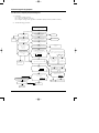
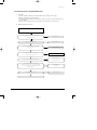
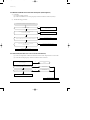
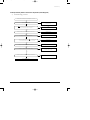
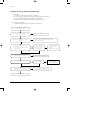
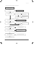
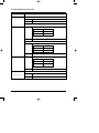
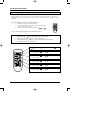
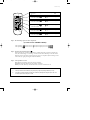
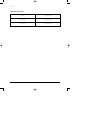
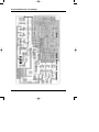
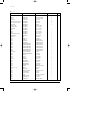
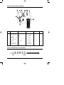
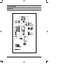
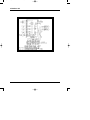
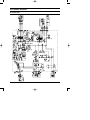
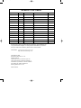
1
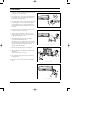
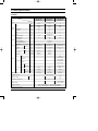
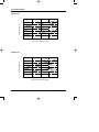
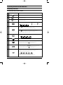
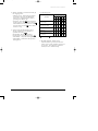
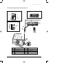
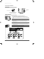
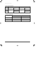
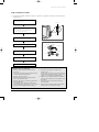
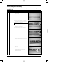
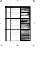
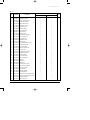
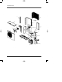
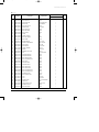
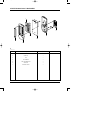
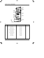
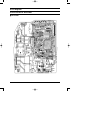
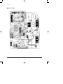
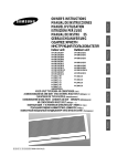
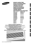
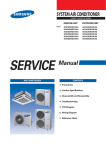
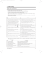
DB98_11868A(1)_cover
3/3/03 11:16 AM
Page 3
ROOM AIR CONDITIONER
INDOOR UNIT
OUTDOOR UNIT
MC26AC2-07
MC26AC2-12
MC26AC2X
SERVICE
Manual
AIR CONDITIONER
CONTENTS
1. Precautions
2. Product Specifications
3. Operating Instructions and
Installation
4. Disassembly and Reassembly
5. Troubleshooting
6. Exploded Views and Parts List
7. Block Diagrams
8. PCB Diagrams
9. Wiring Diagrams
10. Schematic Diagrams
DB98_11868A(1)_1
3/3/03 11:17 AM
Page 1-1
1. Precautions
1. Warning: Prior to repair, disconnect the power
cord from the circuit breaker.
2. Use proper parts: Use only exact replacement
parts. (Also, we recommend replacing parts
rather than repairing them.)
3. Use the proper tools: Use the proper tools and
test equipment, and know how to use them.
Using defective tools or test equipment may
cause problems later-intermittent contact, for
example.
Fig. 1-1 Avoid Dangerous Contact
4. Power Cord: Prior to repair, check the power
cord and replace it if necessary.
5. Avoid using an extension cord, and avoid
tapping into a power cord. This practice may
result in malfunction or fire.
6. After completing repairs and reassembly,
check the insulation resistance.
Procedure: Prior to applying power, measure
the resistance between the power cord and the
ground terminal. The resistance must be
greater than 30 megaohms.
Fig. 1-2 No Tapping and No Extension Cords
7. Make sure that the grounds are adequate.
8. Make sure that the installation conditions are
satisfactory.
Relocate the unit if necessary.
9. Keep children away from the unit while it is
being repaired.
10. Be sure to clean the unit and its surrounding
area.
Fig. 1-3 No Kids Nearby!
Fig. 1-4 Clean the Unit
Samsung Electronics
1-1
DB98_11868A(1)_1
3/3/03 11:17 AM
Page 1-2
MEMO
1-2
Samsung Electronics
DB98_11868A(1)_1
3/3/03 11:17 AM
Page 2-1
2. Product Specifications
2-1 Table
MC26AC2
Model
Item
INDOOR UNIT
INDOOR UNIT
OUTDOOR UNIT
MC26AC2-07
MC26AC2-12
MC26AC2X
Type
Wall-Mounting Multi Split
kW
2.05 x 2
3.5
7.6
BTU/h
6,995 x 2
11,942
25,932
Kcal/h
1,763x2
3,009
6,535
\/h
0.9
1.5
-
m3/min
6
8
-
Noise
dB
39
42
60
Power
ø-V-Hz
Cooling
Performance
Dehumidifying
Air volume
Power
1-220-240V~, 50Hz
Power Consumption
W
1,250
1,210
2,460
Operating Current
A
5.5
5.4
10.9
Starting Current
30
A
Power Cord (Option)
2.5 x 3core
Connection Cable (Option)
1.0 x 4core
Fuse Capacity
Outer
WxHxD
Dimension
Weight
A
3.15
3.15
-
mm
790 x 245 x 165
790 x 245 x 165
880 x 638 x 310
inch
31.1 x 9.64 x 6.50
31.1 x 9.64 x 6.50
34.65 x 25.1 x 12.2
kg
7.7
7.7
60
Liquid
OD(mm)xL(m)
ø6.35 x 5
ø6.35 x 5
-
Gas
OD(mm)xL(m)
ø9.52 x 5
ø9.52 x 5
-
OD(mm)xL(m)
ø18.0 x 2
ø18.0 x 2
-
Type
-
-
Rotary
Model name
-
-
Capacitor
-
Refrigerant pipe
Drain hose
A : G8C124JU1EL
Size
Compressor
B : G8C124JU1EL
A : 35µF 450VAC
Motor
B : 35µF 450VAC
Type
Rated output
W
Type
Blower
Motor
Type
Rated output
-
W
Heat exchanger
-
-
-
-
A : 1,060, B : 1,060
Resin
Resin
Steel
Cross-flow
Cross-flow
Propeller
22
22
74
2Row 12Step
2Row 12Step
2Row 36Step
A/B-Unit : Capillary tube
Refrigerant control unit
A : 500
Freezer oil capacity
cc
-
-
B : 500
A-Unit : 920g, B-Unit : 970g
Refrigerant to charge(R410A)
A : RAC12128-9622
Protection device
-
B : RAC12128-9622
Cooling test condition
Indoor unit : DB27˚C WB19˚C
Outdoor unit : DB35˚C WB24˚C
Maximum operation condition
Indoor unit : DB32˚C WB23˚C
Outdoor unit : DB43˚C WB26˚C
Samsung Electronics
2-1
DB98_11868A(1)_1
3/3/03 11:17 AM
Page 2-2
2-2 Dimensions
2-2-1 Indoor Unit
(Unit : mm)
(Front view)
245
Air
in
790
165
Air out
115
(Remote control)
45
22
Installation plate
2-2
Samsung Electronics
DB98_11868A(1)_1
3/3/03 11:17 AM
Page 2-3
Product Specifications
2-2-2 Outdoor Unit
310
(Unit : mm)
(Rear view)
796
(Front view)
660
1000
Samsung Electronics
340
2-3
DB98_11868A(1)_1
3/3/03 11:17 AM
Page 2-4
2-3 Pressure Graph
■ MC26AC2-07
■
10
30.6/22.5
9
27/19
2
Low Pressure [kg/cm G]
11
21.5/14.6
8
7
20
30
40
Outdoor drybulb temperature [deg C]
■ MC26AC2-12
■
10
9
2
Low Pressure [kg/cm G]
30.6/22.5
27/19
8
21.5/14.6
7
6
20
30
40
Outdoor drybulb temperature [deg C]
2-4
Samsung Electronics
DB98_11868A(1)_1
3/3/03 11:17 AM
Page 2-5
3. Operating Instructions and Installation
3-1 Operating Instructions
3-1-1 The Feature of Key in remote controller
NO
FUNCTION OF KEY
NAMED OF KEY
Power On/Off button to start and stop airconditioner or timer set up.
1
(UP)
Temp. up button. To increase the temperatute by the pressing
the temperature button.
(DOWN)
Temp. down button. To decrease the temperature by the pressing
the temperature button.
2
Each time you press this button
Mode is changed in the following order
3
: Auto Mode
: Dry Mode
: Cool Mode
: Fan Only
Press
until the appearance. The air condition cools
the room as quickly as possible. After 30minutes, the air,
the airconditioner is reset automatically to the previous mode.
4
Press
until the appearance. The sleep timer can be used when
you are cooling your room to switch the air conditioner off
automatically after a period of six hours.
5
Each time you press this button,
FAN SPEED is changed in the following order.
6
Adjust air flow vertically.
7
The ON Timer enables you to switch on the air conditioner automatically
after a given period of time that is from 30 minutes to 24 hours.
To cancel the On Time, press the
(Set/Cancel) button.
8
The Off Timer enables you to switch off the air conditioner automatically
after a given period of time that is from 30 minutes to 24 hours.
To cancel the Off Time, press the
(Set/Cancel) button.
To select the 5 way function with the remote control, press the 5 way
button one or more times until the desired mode is selected.
Each time you press the 5 way button.
9
Each 5 way indicator on the indoor unit comes on in order.
Samsung Electronics
3-1
DB98_11868A(1)_1
3/3/03 11:17 AM
Page 2-6
Operating Instructions and Installation
3-1-2 Name & Function of Key in remote controller
1. AUTO MODE : In this mode, operation
COOL mode is selected automatically by
the room temperature of initial operation.
Operation Type
Cool Operation
Room Temp
Tr≥25°C+∆T
Compressor ON
Tr<24°C+∆T
Compressor OFF
∆T= -1°C, -2°C, 0°C+1°C+2°C
∆T is controlled by setting temperature
up/down key of remote controller
* FAN SPEED : AUTO
2. COOL MODE : The unit operates
according to the difference between the
setting and room temperature.
(18°C~30°C)
3. DRY MODE : Has 3 states, each
determined by room temperature.
The unit operates in DRY mode.
*Compressor ON/OFF Time is controlled
compulsorily(can not set up the fan
speed, always breeze).
*Protective function : Low temperature
release. (Prevention against freeze)
4. TURBO MODE : This mode is available in
AUTO, COOL, DRY, FAN MODE.
When this button is pressed at first, the
air conditioner is operated “powerful”
state for 30 minutes regardless of the set
temperature, room temperature.
When this button is pressed again, or
when the operating time is 30 minutes,
turbo operation mode is canceled and
returned to the previous mode.
*But, if you pressed the TURBO button in
DRY or FAN mode that is changed with
AUTO mode automatically.
3-2
5. SLEEP MODE : Sleep mode is available
only in COOL mode.
The operation will stop after 6 hours.
*The setting temperature is automatically
raised by 1°C each 1hour When the
temperature has been raised by total of
2°C, that temperature is maintained.
6. FAN SPEED : Manual (3 step), Auto (4 step)
Fan speed automatically varies depending
on both the difference between setting and
the room temperature.
7. COMPULSORY OPERATION :
For operating the air conditioner without
the remote controller.
*AUTO : The operating is the same
function that AUTO MODE in the remote
controller. And each time you press the
button the 5WAY function is changed as
follow. STD ➝ NATURE ➝ POWER ➝
SAVING ➝ SILENCE ➝ POWER OFF
❊ STD(standard)(
) : General operation Mode
❊ NATURE(
) : The unit is operated
according to health
pattern control
❊ POWER(
) : The unit is operated in
powerful state
❊ SAVING(
) : The unit is operated in
power saving state
❊ SILENCE(
) : The unit is operated
quietly
Each mode has Auto, Cool and SLEEP
operation designed in advance.
Samsung Electronics
DB98_11868A(1)_1
3/3/03 11:17 AM
Page 2-7
Operating Instructions and Installation
8. SWING : BLADE-H is rotated vertically by
the stepping motor.
*Memory louver : When ON/OFF button
is pressed at stop state, the BLADE-H
returns to its original location which is
operating state before stop
*Swing Set : Press the
button under the
remote control is displayed on LCD the
and the blades move up and down. If the
one more time press the
button, blades
location is stop.
10. SELF Diagnosis
LED DISPLAY
STD NATURE POWER SAVING SILENCE TIMER
Check Point
Indoor unit room temperature sensor
error(open or short)
Indoor unit heat exchanger temperature
sensor error(open or short)
Indoor fan mal function
9. 24-Hour ON/OFF Real Setting Timer. :
The air conditioner is turned ON at a
specified time using
.
OFF TIMER : The air Conditioner is
turned OFF at a specified time using
.
*ON TIMER : Only timer LED lights on.
*OFF TIMER : Both timer and operation
LED lights on.
EEPROM error
Option error(option wasn’t set up or
option data error)
: LED blinking
: LED off
11. BUZZER SOUND : Whenever the
ON/OFF button is pressed or whenever
change occurs to the condition which is set
up or select, the compulsory operation
mode, buzzer is sounded "beep".
Samsung Electronics
3-3
DB98_11868A(1)_1
3/3/03 11:17 AM
Page 2-8
3-2 Installation
3-2-1 Selecting Area for Installation
Select an area for installation that is
suitable to the customer's needs.
3-2-1(a) Indoor Unit
1. Make sure that you install the indoor unit
in an area providing good ventilation. It
must not be blocked by an obstacle
affecting the airflow near the air inlet and
the air outlet.
2. Make sure that you install the indoor unit
in an area allowing good air handling and
endurance of vibration of the indoor unit.
3. Make sure that you install the indoor unit
in an area where there is no source of heat
or vapor nearby.
(Fix the unit firmly if it is mounted in a
high place.)
3. Make sure that you install the outdoor
unit in area providing good ventilation
and which is not dusty. It must not be
blocked by any obstacle affecting the
airflow near the air inlet and the air outlet.
4. Make sure that you install the outdoor
unit in area free from animals or plants.
5. Make sure that you install the outdoor
unit in area not blocking the traffic.
6. Make sure that you install the outdoor
unit in area easy to drain condensed water
from the indoor unit.
5. Make sure that you install the indoor unit
in an area away from TVs, audio units,
cordless phones, fluorescent lighting
fixtures and other electrical appliances
(at least 1 meter).
7. Make sure that you install the outdoor
unit in area which provides easy
connection
within the maximum allowable length of a
coolant pipe(10 meters).
Note
1. Add 10 grams of refrigerant (R410A) for every
1 meter if the pipe length exceeds the
standard pipe length of 5 meters.
2. Maintain a height between the indoor and
outdoor units of less than 3 meters.
6. Make sure that you install the indoor unit
in an area which provides easy pipe
connection with the outdoor unit, and
easy drainage for condensed water.
8. Make sure that you install the outdoor
unit in an area which is large enough to
accommodate the measurements shown in
figure on the next page.
4. Make sure that you install the indoor unit
in an area from which hot or cool air is
spread evenly in a room.
7. Make sure that you install the indoor unit
in an area which is large enough to
accommodate the measurements shown in
figure on the next page.
3-2-1(b) Outdoor Unit
1. Make sure that you install the outdoor
unit in area not exposed to the rain or
direct sun light.
(Install a separate sunblind if exposed to
direct sun light.)
2. Make sure that you install the outdoor
unit in area allowing good air moment,
not amplifying noise or vibration,
especially to avoid disturbing neighbours.
3-2-1(c) Remote Control Unit
1. Make sure that you install the remote
control unit in an area free from obstacles
such as curtains etc, which may block
signals from the remote control unit.
2. Make sure that you install the remote
control unit in an area not exposed to
direct sunlight, and where there is no
source of heat.
3. Make sure that you install the remote
control unit in an area away from TVs,
audio units, cordless phones, fluorescent
lighting fixtures and other electrical
appliances (at least 1 meter).
Caution :
It is harmful to the air conditioner if it is used in the following environments: greasy areas (including areas near machines),
salty areas such as coast areas, areas where sulfuric gas is present such as hot spring areas. Contact your dealer for
advice.
3-4
Samsung Electronics
DB98_11868A(1)_1
3/3/03 11:17 AM
Page 2-9
Operating Instructions and Installation
3-2-2 Installation diagram of indoor unit and outdoor unit
A Indoor unit gas leak test check point
Indoor unit
Piping may be laid to the rear, left,
right or down .
3
Left
Right
2
Rear
Piping
Rear
Down
Tape vinyl
30mm or more
1
B Drain hose installation
125mm or more
125mm
or more
Cut the piping hole
sloped slightly
7
A
5
B
6
100
mm
600mm or more
Remote control
or m
ore
4
100
mm
or m
A-UNIT
600m
m or
ore
Outdoor unit check point
B-UNIT
more
10
1
Piping (Liquid) 1/4"
6
Clamper tube
2
Piping (Gas) 3/8"
7
Installation plate
3
Installation tube
8
Pipe-connection
4
Vinyl tape
9
Screw
5
Putty
10
Drain hose
Samsung Electronics
3-5
DB98_11868A(1)_1
3/3/03 11:17 AM
Page 2-10
Operating Instructions and Installation
3-2-2(a) Fixing the Installation Plate
1. Determine the position of the pipe and drain hose
hole using the right figure and drill the hole with an
inner diameter of 65mm so that it slants slightly
downwards.
Installation plate
Pipe hole
(ø65mm)
2. If you are fixing the indoor unit to a… Then follow
Steps…
3.
Window frame
4 to 6.
3. Fix the installation plate to the wall in a manner
appropriate to the weight of the indoor unit.
60
(Unit : mm)
252
If you are mounting the plate on a concrete wall
with anchor bolts, the anchor bolts must not project
by more than 20mm.
275
30
90
Wall
140
4. Determine the positions of the wooden uprights to
be attached to the window frame.
410~730
(Unit : mm)
5. Attach the wooden uprights to the window frame in
a manner appropriate to the weight of the indoor
unit.
6. Using tapped screws, attach the installation plate to
the wooden uprights, as illustrated in the last figure
opposite.
3-2-2(b) Purging the Unit
On delivery, the indoor unit is loaded with an inert
gas. All this gas must therefore be purged before
connecting the assembly piping. To purge the inert gas,
proceed as follows.
Unscrew the caps at the end of each pipe.
Result : All inert gas escapes from the indoor unit.
•
3-6
To prevent dirt or foreign objects from getting
into the pipes during installation, do NOT
remove the caps completely until you are ready
to connect the piping.
Samsung Electronics
DB98_11868A(1)_1
3/3/03 11:17 AM
Page 2-11
Operating Instructions and Installation
3-2-2(c) Connecting the Assembly Cable.
The outdoor unit is powered from the indoor unit via the assembly
cable. If the outdoor unit is more than five metres away from the
indoor unit, the cable must first be extended to a maximum of ten
metres.
1. Extend the assembly cable if necessary.
2. Open the front grille by pulling on the tabs on the lower right
and left sides of the indoor unit.
3. Remove the screw securing the connector cover.
Indoor
unit
4. Pass the assembly cable through the rear of the indoor unit and
connect the assembly cable to terminals N1 to 1.
1 2
3
E
• Each wire is labelled with the corresponding terminal
number.
Earth
terminal
5. Firmly fix the ass’y cable with clamp wire holder.
Outdoor 1
unit
2
3
1 2 3
(L) (N) COM
Earth terminal
E
6. Pass the other end of the cable through the 65mm hole in the
wall.
E
7. Replace the connector cover, carefully tightening the screw.
8. Close the front grille.
9. For further details on how to plug the other end of the assembly cable into the outdoor unit, refer to page 3-8.
3-2-2(d) Installing and Connecting the Indoor Unit Drain Hose
Care must be taken when installing the drain hose for the indoor unit to ensure that any condensation water is correctly drained outside. When passing the drain hose through the 65mm hole
drilled in the wall, check that none of the following situations occur.
5cm
less
The hose must
NOT slope upwards.
The end of the drain
hose must NOT be
placed in water.
Do NOT bend the
hose in different
directions.
Keep a clearance of at
least 5cm between the
end of the hose and the
ground.
Do NOT place the end
of the drain hose in a
hollow.
To install the drain hose, proceed as follows.
1. If necessary, connect the 2-metre extension to the drain hose.
2. If you are using the extension, insulate the inside part of the extension drain hose with a
shield.
3. Pass the drain hose under the refrigerant piping, taking care to keep the drain hose tight.
4. Pass the drain hose through the hole in the wall, making sure that it is sloping downwards, as
shown in the illustrations above.
The hose will be fixed permanently into position once
the whole installation has been tested for gas leaks;
Shield
Drain hose
Samsung Electronics
Extension drain hose
3-7
DB98_11868A(1)_1
3/3/03 11:17 AM
Page 2-12
Operating Instructions and Installation
3-2-2(e) Outdoor unit installation
GAS LEAK TEST
Outdoor unit
check point
Indoor unit check point
Check for gas leak from the flare nut
connections with leak detector.
WIRING CONNECTION
Two electric cables must be connected to the outdoor unit:
• The assembly cable connecting the indoor unit to the outdoor unit.
• The power cable connecting the auxiliary circuit breaker to the outdoor
unit.
1 Remove the terminal board cover on the side of the outdoor unit.
2 Connect the assembly cable to terminals 1 to 5 and connect the power cable to
therminals A to B.
√ Each wire is labelled with the corresponding terminal number.
√ Ensure the wire number of the indoor unit and the terminal number of
the outdoor unit.
3 Connect the earth wires to the earth terminals.
√ Refer to the page opposite for further details on how to check that
earthing is correct.
4 Replace the terminal board cover, carefully tightening the screw.
5 Connect the power cable to the auxiliary circuit breaker.
Outdoor unit
3
Terminal Block COM
Indoor Unit
2
(N)
1
(L)
3
3
COM COM
2
(N)
1
(L)
2
(N)
Outdoor Unit
MC26AC2-12
MC26AC2X
MC26AC2-07
Earth
A
E terminal
B
Circuit Breaker
(Main Power cable)
1
2
3
1
5
2
3
Assembly
cable
1
2
3
5
1
2
3
A-unit
MC26AC2-12
3-8
2
3
5
Earth
terminal
1
2
3
Earth
terminal
Indoor unit
1
5
Earth
terminal
1
2
3
B-unit
MC26AC2-07
5
Earth
terminal
1
Earth
terminal
1
2
2
3
3
5
Earth
terminal
C-unit
MC26AC2-07
Samsung Electronics
DB98_11868A(1)_1
3/3/03 11:17 AM
Page 2-13
Operating Instructions and Installation
Grounding
(The parts for this work are optional)
• A grounding terminal can be found on
the outdoor unit as illustrated.
1. When an existing grounding terminal is
avilable.
(Grounding wire of ø1.6mm or larger<solid
wire>or 2mm2 or larger <standard wire>)
Terminal used
exclusively for
grounding
Grounding resistance:
less than 100 ohms
(existing grounding electrode)
Grounding screw hole
2. Use of a grounding electrode.
• Specifications of grounding electrode.
Carbon plastic
Steel core
PVC-insulated wire(2mm2x3.5m), green
Samsung Electronics
Terminal, M4
3-9
DB98_11868A(1)_1
3/3/03 11:17 AM
Page 2-14
Operating Instructions and Installation
3-2-2(f) Air-Purge Procedure
1. Connect each assembly pipe to the appropriate valve on the
outdoor unit and tighten the flare nut.
Indoor unit
Outdoor unit
A
Gas pipe side C
B
Liquid pipe side D
2. Connect the charging hose of low pressure side of
manifold gauge to the packed valve having a service port
(3/8” Packed valve) as shown at the figure.
3. Open the valve of the low pressure side of manifold gauge
counter-clockwise.
4. Purge the air from the system using vacuum pump for about
30 minutes.
- After that, please recheck that pressure is staloilization.
- Close the valve of the low pressure side of manifold gauge
clockwise.
- Remove the hose of the low pressure side of manifold
gauge.
Vacuum Pump
5. Set valve cork of both liquid side and gas side of packed
valve to the open position.
Valve stem
B
(liquid)
6. Mount the valve stem nuts to the 2-way and 3-way valve.
6. And mount the service port cap to 3-way valve.
A
(gas)
Stem cap
7. Check for gas leakage.
6. - At this time, especially check for gas leakage from the
3-way valve’s stem nuts, and from the service port cap.
3-10
Samsung Electronics
DB98_11868A(1)_1
3/3/03 11:17 AM
Page 2-15
Operating Instructions and Installation
3-2-2(g) Refrigerant Refill
• Refill an air-conditioner with refrigerant when refrigerant has been leaked at installing or using.
1. Vacuum system with pump (for new
installation, leakage).
2. Turn the 3-way valve clockwise to close,
connect the pressure gauge(low pressure
side) to the service valve, and open the
3-way valve again.
Suspension hook
High
pressure
gauge
Compound
gauge
3. Connect the tank to refill with Refrigerant
Hand
wheel
Finger tight
fittings
4. Set the unit to Low pressure checking mode.
* Press the ON/OFF switch for 5 second.
* All lamps blink on the indoor unit.
5. Check the pressure indicated by the
pressure gauge(low pressure side).
* Refer to Low pressure graph.
For mounting
other end of
hose when
not in use
Connected to
high pressure
side
INDOOR
A-UNIT
INDOOR
B-UNIT
Vacuum
pump
INDOOR
C-UNIT
6. Open the refrigerant tank and fill with refrigerant until the rated pressure is reached.
* It is recommended not to pour the refrigerant in too quickly, but gradually while
operating a pressure valve.
R410A
7. Stop operation of the air conditioner.
8. Close the 3-way valve, disconnect the
pressure gauge, and open the 3-way valve
again.
9. Close the cap of each valve.
Samsung Electronics
3-11
DB98_11868A(1)_1
3/3/03 11:17 AM
Page 2-16
Operating Instructions and Installation
3-2-2(h) Refrigerant Adjustment
Class
For service
For installation
Connection
Pipe Length
5m Max.
5~10m
Air-Purge
Method
Refrigerant
Adjustment
Air-Purge
Method
Refer to the
detailed Air-Purge
Procedure
Unnecessary
Purge air using a
vaccum pump
Add 10g of refrigerant
R410A(Add as liquid
state) for every 1m.
Refrigerant
Quantity
refer to
specification sheet
Add 10g of refrigerant
R410A(Add as liquid
state) for every 1m.
3-2-2(i) Flare nut fixing torque
Torque (kg-cm)
Outer diameter
3-12
Fixing Torque
Final Torque
ø 6.35 (Liquid Side)
160
200
ø 9.52 (Gas Side)
300
350
ø 12.7 (Gas Side)
500
550
Samsung Electronics
DB98_11868A(1)_1
3/3/03 11:17 AM
Page 2-17
Operating Instructions and Installation
3-2-2(j) "Pump down" Procedure
•
Pump down shall be carried out when an evaporator is replaced or when the unit is relocated
in another area.
1. Remove the caps from the 2-way valve
and the 3-way valve.
2-Way Valve
2. Turn the 3-way valve clockwise to close
and connect a pressure gauge(low
pressure side) to the service valve, and
open the 3-way valve again.
3-Way Valve
3. Set the unit to cool operation mode.
(Check if the compressor is operating.)
4. Turn the 2-way valve clockwise to close.
Valve Stem
2-Way Valve
(liquid)
5. When the pressure gauge indicates "0"
turn the 3-way valve clockwise to close.
3-Way Valve
(gas)
Stem cap
6. Stop operation of the air conditioner.
7. Close the cap of each valve.
Relocation of the air conditioner
Relocation of the air conditioner
•
5. Disconnect the pipe connected to the
outdoor unit.
At this time, cover the valve of the outdoor
unit and the other pipe using a cap or vinyl
plug to avoid foreign material entering.
Refer to this procedure when the unit is
relocated.
1. Carry out the pump down procedure (refer
to the details of 'pump down').
2. Remove the power cord.
3. Disconnect the assembly cable from the
indoor and outdoor units.
4. Remove the flare nut connecting the indoor
unit and the pipe.
At this time, cover the pipe of the indoor
unit and the other pipe using a cap or vinyl
plug to avoid foreign material entering.
Samsung Electronics
6. Make sure you do not bend the connection
pipes in the middle and store together with
the cables.
7. Move the indoor and outdoor units to a
new locatioon.
8. Remove the mounting plate for the indoor
unit and move it to a new location.
3-13
DB98_11868A(1)_1
3/3/03 11:17 AM
Page 2-18
MEMO
3-14
Samsung Electronics
DB98_11868A(1)_1
3/3/03 11:17 AM
Page 2-19
4. Disassembly and Reassembly
Stop operation of the air conditioner and remove the power cord before repairing the unit.
4-1 Indoor Unit
No
Parts
1
Front Grille
Procedure
Remark
1) Stop the air conditioner operation and block
the main power.
2) Separate tape of front panel upper.
3) Contract the second finger to the left, and
right handle and pull to open the inlet grille.
4) Take the left and right filter out.
*Taking off the deodorizing filter.
5) Loosen one of the right fixing screw and
separate the terminal cover.
6) Loosen three fixing screws of front grille.
7) Pull the upper left and right of discharge
softly for the outside cover to be pulled out.
8) Pull softly the lower part of discharge and
push it up.
Caution;
Assemble the front panel and fix the
hooks of left and right.
Samsung Electronics
4-1
DB98_11868A(1)_1
3/3/03 11:17 AM
Page 2-20
Disassembly and Reassembly
No
Parts
2
Ass’y Tray
Drain.
Procedure
Remark
1) Do “1”above.
2) Take all the connector of PCB upper side out.
(Inclusion Power cord)
3) Separate the outdoor unit connection wire
from the terminal block.
4) If pulling the Main PCB up. It will be taken
out.
3
Electrical Parts
(Main PCB)
4
Heat
Exchanger
1) Do “1”, “2” above.
Separate the drain hose from the extension
drain hose.
2) Pull tray drain out from the back body.
1) Do “1” and “2”, “3” above.
2) Loosen two fixing earth screws of right side.
3) Separate the connection pipe.
4) Separate the holder pipe at the rear side.
5) Loosen the three fixing screws of right and
left side.
6) Lifting the heat exchanger up a little to push
the up side for separation from the indoor
unit.
5
Fan Motor and
Cross Fan
1) Do “1”, “2”, ”3”, “4” above.
2) Loosen the fixing two screws and separate
the motor holder.
3) Loosen the fixing screw of fan motor.
(By use of M3 wrench)
4) Separate the fan motor from the fan.
5) Separate the fan from the left holder bearing.
4-2
Samsung Electronics
DB98_11868A(1)_1
3/3/03 11:17 AM
Page 2-21
4-2 Outdoor Unit
No
Parts
1
Cabinet
Procedure
Remark
1) Turn off the unit and remove the power
cable.
2) Remove the top cover.
3) Remove the control box cover.
4) Unplug the ass'y cable.
5) Remove the cabi-side.
6) Remove the cabi-front.
* When you assemble the parts, check if the
each parts and electric connectors are fixed
firmly.
2
Fan Motor
&
Propeller Fan
1) Do Procedure “1” above.
2) Remove the nut flange.
(Turn to the right to remove as it is a left
turned screw)
3) Disassemble the propeller fan.
Samsung Electronics
4-3
DB98_11868A(1)_1
3/3/03 11:17 AM
Page 2-22
MEMO
4-4
Samsung Electronics
DB98_11868A(1)_1
3/3/03 11:17 AM
Page 2-23
5. Troubleshooting
5-1 Items to be checked first
1) The input voltage should be rating voltage ±10% range.
The airconditioner may not operate properly if the voltage is out of this range.
2) Is the link cable linking the indoor unit and the outdoor unit linked properly?
The indoor unit and the outdoor unit shall be linked by 3 cables.
Check the terminals if the indoor unit and outdoor unit are properly linked by the same
number of cables.
Otherwise the airconditioner may not operate properly.
3) When a problem occurs due to the contents illustrated in the table below it is a symptom not
related to the malfunction of the airconditioner.
NO
Operation of air conditioner
Explanation
1
The STD operation indication LED blinks when a
power plug of the indoor unit is plugged in for the first time.
It indicates power is on. The LED stops blinking if the operation
ON/OFF button on the remote control unit is pushed.
2
In a COOL operation mode, the compressor does not
operate at a room temperature higher than the setting
temperature that the IN DOOR FAN should operate.
In happens after a delay of 3 minutes when the compressor is
reoperated. The same phenomenon occurs when a power is on.
As a phenomenon that the compressor is reoperated after a delay of
3 minutes, the indoor fan is adjusted automatically with reference
to a temperature of the air blew.
3
Fan speed setting is not allowed in AUTO or DRY mode.
The speed of the indoor fan is set to LL in DRY mode.
Fan speed is 5 steps is selected automatically in AUTO mode.
4
Compressor stops operation intermittently in DRY mode.
Compressor operation is controlled automatically in DRY mode
depending on the room temperature and humidity.
5
Timer LED only of the indoor unit lights up and the
air conditioner does not operate.
Timer is being activated and the unit is in ready mode.
The unit operates normally if the timer operation is cancelled.
6
The compressor stops intermittently in a COOL mode or DRY
mode, and fan speed of the indoor unit decreases.
The compressor stops intermittently or the fan speed of the indoor
unit decreases to prevent inside/outside air frozen depending on the
inside/outside air temperature.
4) Indoor unit observes operation condition of the air conditioner, and displays self diagnosis
details on thedisplay panel.
NO
Self Diagnosis
Display
1
STD LED blinking (1Hz)
Restore from power failure (input initial power)
2
TIMER LED blinking (1Hz)
Indoor unit Room sensor Error (open or short)
3
STD and TIMER LED blinking (1Hz)
Indoor unit heat exchanger temperature sensor Error (open or short)
4
BIO LED blinking (1Hz)
Indoor fan malfunctioning (for speed is Below 450rpm)
5
STD, BIO and TIMER LED blinking(1HZ)
EEPROM Error
6
All LED blinking(1HZ)
Option Error (option wasn’t setup or option data error)
Samsung Electronics
5-1
DB98_11868A(1)_1
3/3/03 11:17 AM
Page 2-24
5-2 Fault Diagnosis by Symptom
5-2-1 No Power (completely dead)-Initial diagnosis
1)
Checklist :
(1) Is input voltage normal?
(2) Is AC power linked correctly?
(3) Is output voltage of DC regulator IC KA78L05 (IC02) normal? (4.5VDC-5.5VDC)
2)
Troubleshooting procedure
Remove power cord and plug in
again in approx. 5 seconds
Is operation lamp blinking?
NO
YES
YES
Does operation start when
ON/OFF button on the remote
controller unit pushed?
NO
Is DC voltage of PCB
display normal?
NO
Replace
PCB display
Is transmission display of the
remote controller unit blinking?
Is rating voltage ±10% range
applied to the primary side(~,~)
of the “BD71”
NO
Normal
NO
Refer to remote control
unit fault diagnosis
NO
Replace PCB
module.
YES
NO
Is "beep"sound heard from the main
unit?
YES
Is DC voltage of the PCB module
normal?
•Check linkage between
power cord and
terminal tap
•Check fuse
YES
Are voltages of #33 (compressor),
of the micom normal? 5VDC
Is voltage of #32 (indoor fan) of the
micom normal?
Is 325VDC appear in the
secondary side (+, -)
of “BD71”
NO
YES
YES Are voltages at RY71(Compressor) normal?
DC12V Is voltage at SS71(indoor fan)
DC5V
YES
YES
NO
Is voltage at #10 terminal of the Micom normal?
0VDC
Is voltage at #9 terminal of the Micom normal?
5VDC
Replace
SMPS PARTS
NO
Check connections
compressor and
indoor fan.
Replace
RY71 and SS71
NO
YES
Is output voltage of ICO2 normal?
Is voltage at #3 terminal of the micom
normal?
Check PCB pattern.
Replace main PCB.
10ms
YES
NO
YES
Replace ICO2
NO
Is voltage output terminal of
PC814(PC02) normal?
NO
Are voltage at #11 and #12 of the
micom normal?
YES
Replace resonator (X301)
250ns
YES
Is operation normal?
YES
NO
OK
NO
Replace PC814(pc02)
Replace
micom
OK
5-2
Samsung Electronics
DB98_11868A(1)_1
3/3/03 11:17 AM
Page 4-1
Troubleshooting
5-2-2 When the power is not applied(Outdoor unit)
1)
Checklist :
(1) Is the voltage of the power normal? (The rating voltage ±10% range)
(2) Is the power line in good contact?
(3) Are the primary (CN71) and secondary (CN11) connectors of the power trans in
good contact?
(4) Is the power voltage of the IC01 (KA7812) normal? (DC11.5V~DC12.5V)
2) Troubleshooting procedure
Turn off the power, and then turn on the power
in five minutes.
YES
Does the power of the IC01(KA7812) match with
the voltage of DC12V?
NO
Normal operation
YES
NO
Is the F701(3.15A) fuse blown?
Replace the fuse
YES
Is the secondary voltage of the trans normal?
(AC15V~AC25V)
NO
Replace the trans
YES
Is the first voltage of the trans normal?
the rating voltage ±10% range
NO
Replace the trans
YES
Is the rectifying diode(D101~D104) normal?
NO
Check and replace
the rectifying diode
NO
Replace the C102
and C104.
YES
Is the voltage at both ends of the C102
electrolytic condenser in the range of DC16~DC25V?
Is the voltage at both ends of the C104 electrolytic
condenser DC12V?
YES
Is the IC01(KA7812) normal?
NO
Replace the IC01
YES
End
Samsung Electronics
5-3
DB98_11868A(1)_1
3/3/03 11:17 AM
Page 4-2
Troubleshooting
5-2-3 When the Indoor Unit Fan Does Not Operate. (Initial Diagnosis)
1)
Checklist :
(1) Is the indoor unit fan motor properly connected with the connector (CN72)?
(2) Is the AC voltage correct?
(3) Is HALL IC in indoor fan motor properly connected with the connector (CN42)?
(4) Is the running capacitor (CR71) properly connected with PCB board?
2)
Troubleshooting procedure
After unplugging out the power cord should
be reconnected within five seconds.
YES
Check as in the procedure “NO power parts”
Refer to page 5-2.
NO
Does the STD lamp(Green) blink?
YES
NO
Does the Solid State Relay(SS71) work
properly?
Microcomputer is out of order.
Test rod location
+
-
SS71-
SS71-
Normal
Voltage
12V
YES
NO
Is the supply voltage of the fan
motor sufficient?
Test rod location
PCB is
out of order.
Normal
voltage
PCB CN72
Condition
pin #3 and #5
Fan operate
about AC 180V
YES
MF-C is out of order
Fan motor
is out of order.
5-4
PCB should be replaced.
Replace MFC
Fan motor
should be replaced.
Samsung Electronics
DB98_11868A(1)_1
3/3/03 11:17 AM
Page 4-3
Troubleshooting
5-2-4 When the Outdoor Unit Does Not Operate. (Initial Diagnosis)
1)
Checklist :
(1) Is input voltage normal? (The rating voltage ±10% range)
(2) Is the set temperature of the remote control higher than room temperature in COOL
mode?
(3) Is the POWER IN connector (terminal-tab) linked correctly?
(4) Is the outdoor unit properly connected with the TERMINAL BLOCK connector(5P)?
2)
Troubleshooting procedure
(1) Checking procedures for the indoor unit.
After unplugging out the power cord should be
reconnected within five seconds.
NO
Does the operating lamp blink
Check as in the procedure "No Power parts"
Refer to page 5-2.
YES
YES
Room temperature sensor is
out of order
Does the timer lamp blink during operation ?
NO
PCB should be checked.
@
Is the power relay RY71 operated by adjusting the NO !
room temperature?
Test rod location
Microcomputer is
out of order.
YES #
Normal
+
-
Condition
Voltage
IC1 Pin No.63
GND
RY73 ON
DC 4.8V
IC1 Pin No.62
GND
RY72 ON
DC 4.8V
PCB should be
checked.
NO
1) Is the rating voltage ±10% range applied relay between
Terminal Tap(TB71) and RY 71 terminal No #
2) Is the rating voltage ±10% range applied relay between
Terminal Tap(TB71) andCN 71 terminal No !
Power relay is
out of order
Power relay should be
replaced.
A Room operation
YES
“A”Compreessor or outdoor fan-motor replaced
! NO
@ NO
Is the room sensor normal register?
10°C
20°C
30°C
17.96kΩ
12.09kΩ
8.3kΩ
YES #
B Room or C Room operating
Proceed to the checking points for the outdoor unit.
Samsung Electronics
5-5
DB98_11868A(1)_1
3/3/03 11:17 AM
Page 4-4
Troubleshooting
(2) Procedures for checking the outdoor unit.
Turn off the power, and then turn on the
power in 5 seconds.
YES
Does the compressor operate in 2 minutes after
the relay (RY71)
is activated at the indoor unit after 3 minutes?
NO
Normal
YES
Does the photo coupler (IC02, IC03)
corresponding to the indoor units (B & C) operate?
NO
Check and replace the relevant
IC (IC02, IC03).
YES
Is the DC voltage applied to both ends of the C901?
(1) Is the voltage DC6V when either of the indoor
units (B & C) is turned on?
(2) Is the voltage DC8V when both of the indoor
units are turned on?
NO
• Check and replace the resistance
(R901, R928, R931) and diode (D907, D908).
• Check and replace the electrolytic condenser (C901)
YES
(1) Does the N01 pin output of the IC04 maintain "Low"?
(2) Does the N014 pin output of the IC04 maintain "High"?
When either of the indoor units (B & C) is turned on.
(3) Does the N014 pin output of the IC04 maintain "Low"?
When both of the indoor units (B & C) is turned on.
NO
(1) Is the NO3 pin voltage
of the IC04 DC5V?
(2) Is the NO12 pin voltage
of the IC04 DC7V?
• Check and replace the
IC04.
NO
• Check and replace the
resistance.
(R902, R903,R905, R906)
YES
Does the No7 pin output of the IC04 maintain "Low"?
NO
Is the No.5 pin voltage
of the IC04 DC5V?
NO
Check and replace the
R913, R915 and IC04.
Is the voltage at both
ends of the C903 DC10V?
NO
Check and replace the
R911, D901, and C903.
YES
YES
Are the Q901, and 904 in "Turn-off" condition?
Are the Q902, Q903 and Q905 in "Turn-on" condition?
NO
Check and replace each transistor
YES
Does the operation of the Q701 lead to
activation of the compressor relay (RY71)?
NO
Check and replace the Q701 and relay.
(Resistance at both ends of the relay: About 150)
YES
Replace the "B" compressor.
5-6
Samsung Electronics
DB98_11868A(1)_1
3/3/03 11:17 AM
Page 4-5
Troubleshooting
5-2-5 When the Outdoor Unit Does Not Operate. (Initial Diagnosis)
1)
Checklist :
(1) Is input voltage normal?
(2) Is the set temperature of the remote control higher than room temperature in COOL
mode?
(3) Is the POWER IN connector (CN71) linked correctly?
(4) Is the outdoor unit properly connected with the TERMINAL BLOCK connector((N1), 1)?
2)
Troubleshooting procedure
After unplugging out the power cord should be
reconnected within five seconds.
NO
Does the STD lamp blink
Check as in the procedure "No Power parts"
Refer to page 5-2.
YES
YES !
Does the timer lamp blink during operation ?
Room temperature sensor is
out of order
NO
@
#
Test rod location
+
IC4 Pin No.33
Microcomputer is
out of order.
NO
Is the power relay RY71 operated by adjusting the room
temperature?
PCB should be checked.
Normal
-
Condition
Voltage
GND
RY71 ON
DC 4.8V
PCB should be
checked.
NO
Power relay is
out of order
Is rating voltage ±10% range applied relay between Terminal block
NO(N1) and No !
YES
Power relay should be
replaced.
Outdoor unit is
out of order.
!
YES
NO
@
Is the room sensor normal register?
10°C
20°C
30°C
17.96kΩ
12.09kΩ
8.3kΩ
YES
#
Samsung Electronics
5-7
DB98_11868A(1)_1
3/3/03 11:17 AM
Page 4-6
Troubleshooting
5-2-6 When the UP/DOWN Louver Moter Does Not Operate. (Initial Diagnosis)
1)
Checklist :
(1) Is input voltage normal?
(2) Is the UP/DOWN louver motor properly connected with the connector (CN61)?
2)
Troubleshooting procedure
Remove power cord and plug in again in approx. 5 seconds.
NO
Is STD lamp blinking?
Check as in the procedure "No Power parts".
Refer to page 5-2.
YES
YES
Does operation start when swing button of the
remote control unit pushed?
Normal
NO
NO
Micom (IC04) is faulty.
Voltage at pin #58 ~ #61 of micom (ICO4) change?(Squarewave)
YES
NO
Volatge at pin #13 ~ #16 of IC06 (ULN2003AFW)
change?(Squarewave)
Driver IC06 (ULN2003AFW) is faulty.
YES
UP/DOWN louver motor is faulty.
5-2-7 In the mode, When there is no cool air current. Check this first;
(1) Is the set temperature of Remote Control lower than room temperature in Cool mode?
(2) Is the Indoor PCB properly connected with the CN71 connector?
After training on, the Cooling operation should
start in five minutes.
YES
Normal
NO
Is the number #33 of Micom (IC04) DC 5.0 V?
NO
Abnormal Micom
YES
Is the number checking #10 of IC06 (ULN2003AFW) LOW?
NO
Abnormal IC06
RY01 or Cable Check.
PCB should be replaced.
5-8
Samsung Electronics
DB98_11868A(1)_1
3/3/03 11:17 AM
Page 4-7
Troubleshooting
5-2-8 If Operation By Remote Control Unit Is Impossible. (Initial Diagnosis)
1)
Troubleshooting procedure
Remove power cord and plug in again approx. 5 Seconds
NO
Is operation lamp blinking?
Check as in the procedure “NO Power parts”.
Refer to page 5-2.
YES
“
“ sound heard from the indoor unit when ON/OFF
button on the remote control unit pushed?
YES
Normal
NO
YES
Replace battery.
Voltage of battery less than 2.5V (Remote Control Unit)?
NO
NO
LCD display status of REMOCON normal?
LCD is faulty.
YES
Transmission display lamp (
) blinking when
ON/OFF button on the remote control unit pushed?
NO
Replace button.
YES
NO
Voltage at PIN #30 of Remocon Micom change?
Micom is faulty.
YES
Voltage at collecter of Q601 or Q602 change?
NO
Q601(C4375Y) or Q602(C1623Y) is faulty.
IR LED(CL-1L5EU) is faulty.
YES
Voltage at pin #26 of micom (IC04) change (INDOOR UNIT)?
NO
Receiver module is faulty.
YES
Micom (IC04) is faulty.
Samsung Electronics
5-9
DB98_11868A(1)_1
3/3/03 11:17 AM
Page 4-8
Troubleshooting
5-2-9 When the SV-BY is Malfunctioning (Outdoor Unit)
1)
Checklist :
(1) Is the SV1 under normal operating condition?
(2) Is the voltage of the power normal? (the rating voltage ±10% range)
(3) Is the connector (CN76) of the SV-BY in good contact?
(4) Is the resistance at both ends of the solenoid about 1.4kΩ ?
2)
Checking procedures
(1) When either of the indoor units (B & C) is turned on
Turn off the outdoor power, and then turn
on the power in 5 seconds.
YES
Does the SV-BY operate when either of the
indoor units is turned on?
YES
Normal
NO
Is the voltage of DC6V applied to both ends
of the C901?
NO
• Check and replace the relevant IC (IC02, IC03).
• Check and replace the resistance (R901, R928, R931),
and diode (D907, D908).
YES
(1) Does the No14 pin output of the IC04
maintain "High"?
(2) Does the No1 pin output of the IC04
maintain "Low"?
NO
YES
Are the Q906, and Q907 in "turn-on" condition?
Is the Q908 in "turn-off" condition?
(1) Is the No12 pin voltage
of the IC04 DC7V?
(2) Is the No3 pin voltage
of the IC04 DC5V?
NO
• Check and replace the IC04.
• Check and replace the
resistance
(R902, R903, R905, R906).
YES
NO
Check and replace each transistor
YES
Is the No8 pin output of the IC04 in "High"
condition?
NO
YES
Does the operation of the Q702 lead to
activation of the SV-BY relay (RY72)?
Is the No10 pin voltage
of the IC04 DC7V?
NO
• Check and replace the IC04.
• Check and replace the
resistance (R922, R924).
YES
NO
Check and replace the Q702 and relay.
(Resistance at both ends of the relay: 400Ω )
YES
Replace the SV-BY
5-10
Samsung Electronics
DB98_11868A(1)_1
3/3/03 11:17 AM
Page 5-1
Troubleshooting
(2) When all of the indoor units (B & C) are turned off
Turn off the outdoor power, and then turn on
the power in 5 seconds.
YES
Is the SV1 turned off after operating for
about 2 minutes
when all of the indoor units (B & C)
are turned off?
NO
Normal
NO
(1) Does the No14 pin output of
the IC04 maintain "High"?
(2) Does the No1 pin output of "Low"?
(1) Is the No.12 pin voltage
of the IC04 DC7V?
(2) Is the No.3 pin voltage
of the IC04 DC5V?
NO
• Check and replace the IC04.
• Check and replace the IC04
maintain resistance
(R902, R903,R905, R906).
NO
YES
YES
Is the voltage at both
ends of the C901 0V?
• Check and replace the
IC02-IC03.
• Check and replace the C901.
NO
YES
Are the Q906 and Q908 in "turn-on"
condition?
Is the Q907 in "turn-off" condition?
NO
Check and replace each transistor
YES
Is the No8 pin output of
the IC04 in "High" condition?
YES
NO
Is the No10 pin voltage
of the IC04 DC7V?
NO
• Check and replace the IC04.
• Check and replace the R922,
and R924.
The "High" condition should be maintained for about 2 minutes
until the voltage of about DC7V or higher is applied to the C904.
Is the voltage charged to
the C904 above DC7V?
NO
Check and replace the R920 and R921.
Check and replace the C904.
YES
Does the No8 pin output of
the IC04 change from "High" to "Low"?
NO
IC04 Check and replace
The output is changed from "High" to "Low" when charging
to the C904 is completed.
YES
Does the turning on and then
turning off of the Q702 lead to
turning off of the SV-BY relay (RY72)?
NO
Check and replace the Q702 and relay.
(Resistance at both ends of the relay: 400Ω)
YES
Replace the SV-BY solenoid.
Samsung Electronics
5-11
DB98_11868A(1)_1
3/3/03 11:17 AM
Page 5-2
Troubleshooting
5-2-10 When the SV-B is malfunctioning
1)
Checklist :
(1) Is the SV-B under normal operating condition?
(2) Is the voltage of the power normal? (the rating voltage ±10% range)
(3) Is the SV-B connector (CN75) in good contact?
(4) Is the resistance at both ends of the solenoid about 1.4kΩ?
2)
Checking procedures
Turn off the outdoor power, and then turn it on
after 5 seconds
YES
Does the SVA operate when the room B among the indoor
unit room B and room C is turned on?
YES
Normal operation
NO
Does the photo-coupler (IC02) for the room B among the
indoor unit room B and room C operate?
NO
Check and replace the photo coupler (IC02)
YES
Is the voltage of about DC5V or above applied to
both ends of the C905?
NO
• Check and replace the R929 and R930
• Check and replace the C905
NO
• Check and replace the R901, R928 and D908
• Check and replace the C901
YES
Is the voltage of about DC6V or above applied to
both ends of the C901?
NO
YES
! Is the 14th pin output of the IC04 maintained at
"High" level?
@ Is the Ist pin output of the IC04 maintained at
"Low" level?
NO
NO
•Check and
replace the IC04
•Check and
replace the
resistance(R902,
R903,R905,R906)
YES
YES
Are the Q906, Q907, and Q909 under turn on condition,
and is the Q908 under "turn off" condition?
! Is the voltage of the 12th pin
for the IC04 about DC7V?
@ Is the voltage of the 3rd pin
of the IC04 about DC5V?
NO
Check and replace the relevant transistor
YES
Is the Q703 turned. on, indicating the
operating of the SV-B relay (RY73)?
NO
Check and replace the D905, D909, and Q703 relay
(Coil resistance at both ends of the relay:about 400Ω)
YES
Replace the SV-B solenoid valve
5-12
Samsung Electronics
DB98_11868A(1)_1
3/3/03 11:17 AM
Page 5-3
Troubleshooting
5-2-11 When the SV-C is malfunctioning
1)
Checklist :
(1) Is the SV-C under normal operating condition?
(2) Is the voltage of the power normal? (the rating voltage ±10% range)
(3) Is the SV-C connector (CN74) in good contact?
(4) Is the resistance at both ends of the solenoid about 1.4kΩ?
2)
Checking procedures
Turn off the outdoor power, and then turn it on
after 5 seconds
YES
Does the SVB operate when the room C among the indoor
unit room B and room C is turned on?
YES
Normal operation
NO
Does the photo-coupier (IC03) for the room C among the
indoor unit rooms B and room C operate?
NO
Check and replace the photo coupler(IC03)
YES
Is the voltage of about DC5V or above applied to both
ends of the C906?
NO
• Check and replace the R932, and R933
• Check and replace the C906
NO
• Check and replace the R901, R931, and D907
• Check and replace the C901
YES
Is the voltage of about DC6V or above applied to both
ends of the C901?
YES
! Is the output of the 14th pin of the IC04
maintained a "Hight" level?
@ Is the output of the lst pin of the I04 maintained
at "Low" level?
NO
! Is the voltage of the 12th pin
of the IC04 about DC7V?
@ Is the voltage of the 3rd pin
of the IC04 about DC5V?
NO
• Check the
IC04
• Check and
replace the
resistance
(R902, R903,
R905, R906)
YES
YES
Are the Q906, Q907 and Q909 turned on with the Q908
being turned off?
NO
Check and replace the relevant transistor
YES
Is the Q704 turned on, indicating the operating condition
of the SV-C relay (RY74)?
NO
Check and replace the D906, D910, and Q704 relay
(Coil resistance at both ends of the relay : about 400Ω)
YES
Replace the SV-C solenoid valve
Samsung Electronics
5-13
DB98_11868A(1)_1
3/3/03 11:17 AM
Page 5-4
Troubleshooting
5-2-12 When the SV-B and SV-C are malfunctioning with all of the indoor units
(B & C) turned off
1)
Checklist :
(1) Are the SVA and SVB under normal operating condition?
(2) Is the voltage of the power normal? (the rating voltage ±10% range)
(3) Are the SV-B (CN75) and SV-C (CN74) connectors in good contact?
(4) Is the resistance at both ends of the solenoid about 1.4kΩ?
2)
Checking procedures
Turn off the outdoor power, and then
turn on the power in 5 seconds.
YES
Are the SVA and SVB operate turned off after
operating for about 2 minutes when all
of the indoor units (B & C) are turned off?
YES
Normal
NO
(1) Does the No14 pin output of the IC04
maintain "High"?
(2) Does the No1 pin output of the IC04
maintain "High"?
(1) Is the No12 pin voltage
of the IC04 DC7V?
(2) Is the No3 pin voltage
of the IC04 DC5V?
NO
NO
• Check and replace the IC04.
• Check and replace the resistance
(R902, R904, R905 R906).
YES
YES
Is the voltage at both
ends of the C901 0V?
NO
YES
NO
Are the Q906 and Q908 in "turn-on" condition?
Are the Q907 and Q909 in "turn-off" condition?
• Check and replace the IC02,
and IC03.
• Check and replace the C901.
Check and replace each transistor.
YES
Is the No8 pin output of
the IC04 in "High" condition?
NO
YES
Is the No10 pin voltage
of the IC04 DC7V?
YES
NO
• Check and replace the IC04.
• Check and replace the R922,
and R924.
The "High" condition should be maintained for about 2 minutes until a voltage
of above DC7V is charged to the C904.
Do the SVA and SVB operated
when the Q703, and Q704 are turned on?
NO
• Check and replace the D903, D905, D906 and Q703 Q704.
• Check and replace the SVA and SVB solenoid.
NO
• Check and replace the R920 and R921.
• Check and replace the C904.
YES
Is the voltage charged to
the C904 above DC7V?
YES
Is the No8 pin output of the
IC04 changed from "High" to "Low"?
NO
IC04 Check and replace
YES The output is changed from "High" to "Low" when the charging to the C904 is completed.
Are the SV-B and SV-C relays (RY73, 74)
turned off when the Q703 and Q704 are
turned off.
NO
• Check and replace the Q703, and Q704.
• Check and replace the relay when necessary.
(Resistance at both ends of the relay: About 400Ω)
YES
Replace the SV-B and SV-C solenoids.
5-14
Samsung Electronics
DB98_11868A(1)_1
3/3/03 11:17 AM
Page 5-5
5-3 PCB Inspection
5-3-1 Cautions for Part Replacement
1. The human body carries much static
electricity. Before touching a part for
repair, replacement or the similar purpose,
be sure to touch a grounded metallic
portion by hand to let the static electricity
go through the metallic portion to the
earth.
Especially when handling any micro
computer or IC, carefully remove such
static electricity before touching them.
2. When repairing any part on a work bench,
be sure to place an insulative sheet on the
bench and always keep the sheet surface
neat without any metal fragments. If any
such fragment touches a part, a secondary
trouble will possibly be caused in the part.
3. Before replacing any parts, be sure to turn
off the power supply. If such replacement
is done with the power supply kept on, an
electric shock, short circuit or destruction
of a part may result.
4. During replacement or repair of a part,
carefully handle it : The printed circuit
board has fine lead wires (jumper wires)
and glass-made parts (diode) on its
substrate.
So if a circuit board is roughly handled,
such lead wires and parts will be easily
broken or damaged by bending or shock.
5. When soldering the lead wires of any new
part, be sure to polish them using an
emery paper or the like before solding
them.
Since the lead wires of any new part are
covered with an oxide film, solder cannot
adhere to the lead wires if not polished.
6. When soldering any part, care should be
exercised not to apply any high-wattage
soldering iron to the part for a long time.
Some parts are of so low a heat resistance
that they may be broken or have the
properties changed if a soldering iron is so
applied (Otherwise, the pattern may
possibly be separated and raised).
7. The heat of the soldering iron should be
transfered to the entire object to be
soldered. If the solder pieces are not well
fused due to insufficient transfer of the
heat from the soldering iron, no satisfactory electrical continuity can be assured
even if the soldered objects appear well
connected to each other.
8. The solder used should be limited to a
minimum. If excessive solder is used, it
will cause inter-pattern contact, which
may cause malfunction of the circuit.
5-3-2 Procedure
The parts should be replaced in the following procedure.
Check for any faulty part.
Detach the faulty part.
Replace it with a new part.
Check the operation of the new part.
The repair is completed.
Samsung Electronics
5-15
DB98_11868A(1)_1
3/3/03 11:17 AM
Page 5-6
Troubleshooting
5-3-3 Detailed Procedure
No.
Malfunction
Checking point (symptoms)
the AC terminal and confirm
1. Is the broken(open)?
Voltage over
∆
1
∆
Pull out the power plug from
Causes
Indoor unit fan
the fuse on the PCB assembly
motor short-circuit
Voltage check
SMPS circuit is faulty
1. AC voltage at BD71(~,~)?
∆
SMPS circuit is faulty
∆
: rating voltage ± 10% range
PC02, R202-R205
2. DC voltage at BD71(+,-)?
: about 325[v] ± 10%
2
Turn the power on.
3. DC voltage at IC02
: IN-GND ➔ DC12[v]
: OUT-GND ➔ DC5[v]
4. Voltage waveform at Q201
: collector-GND ➔ squarewave
Voltage check
∆
IC06 is faulty
∆
1. check voltage of IC06
SMPS circuit is faulty
RY71 is faulty
(pin#10,pin#8)
3
Set the TURBO mode
: relay on ➔ 0.7[v]
: relay off ➔ 12[v]
2. Voltage at terminal block
((N1) -1) ➔ rating voltage
5-16
Samsung Electronics
DB98_11868A(1)_1
3/3/03 11:17 AM
Page 5-7
5-4 Fault Diagnosis of Major Parts
Diagnosis
Parts
Temp.Sensor
Heat ex. Sensor
Measure resistance with a tester.
Normal
8KΩ~27KΩ at ambient temperature (+0°C ~ +30°C)
Abnormal
∞, OΩ … open or short
Measure resistance between terminals (CN72) with a tester
Indoor Fan Motor
Normal
Abnormal
At ambient temperature (10°C ~ 30°C)
between
Resistance
Red, Yellow
190±10Ω
Red, Blue
170 ±10Ω
∞, OΩ … open or short
Measure the voltage between ground and signal wire of the fan motor
Normal
Outdoor Fan Motor
(UP/DOWN swing motor)
Samsung Electronics
Voltage
Gray, Orange
0.5V~4.5V
Yellow, Orange
5V
Abnormal
Abnormal if voltage does not change from 0V to 5V.
Normal
At ambient temperature (10°C ~ 30°C)
Abnormal
Stepping Motor
between
between
Resistance
Red, Blue
100±10Ω
Red, White
130±10Ω
∞, OΩ … open or short
Measure resistance between red wire and each terminal.
Normal
Approx. 380Ω at ambient temperature (20°C ~30°C)
Abnormal
∞, OΩ … open or short
5-17
DB98_11868A(1)_1
3/3/03 11:17 AM
Page 5-8
5-5 Set up the Model option
The Method for Setting up the model option with remocon
• It is necessary to set up option code after replacing the main-PCB as a service parts.
Make sure that you can set up the option of code the remote controller after you replace the
main PBA otherwise, the unit won’t be working properly and all LED lamps on display will be
flickering.
Step 1 : Preparing the remocon to main PCB option set
1st Remove the battery from the remocon.
2nd Press the temperature raise/down button simultaneously
and insert the battery again.
3rd Make sure the remocon display shown as
.
Step 2 : Second stage preparation of the remocon option set.
❈ Note ; In case the wrong letter has been selected, continue to press the button until the correct letter appears.
1st
If the first stage number “ ” appears on the display, proceed to the second stage.
2nd
3rd
Every time the ! and & button, “ ” and “ ” each continue to appear.
Whenever pressing the @, #, $, %, ^, *, (, ), 1, 2 button, the number increase from
0~9(0123456789) and A, b, C, d, E, F each time.
! If the first number is
appear.
5-18
, it is correct otherwise press
until
@ When pressing the
select one of them.
button
~
appear on the display,
# When pressing the
select one of them.
button
~
appear on the display,
$ When pressing the
select one of them.
button
~
appear on the display,
% When pressing the
select one of them.
button
~
appear on the display,
^ When pressing the
select one of them.
button
~
appear on the display,
Samsung Electronics
DB98_11868A(1)_1
3/3/03 11:17 AM
Page 5-9
Troubleshooting
! If the first number is
appear.
, it is correct otherwise press
until
@ When pressing the
select one of them.
button
~
appear on the display,
# When pressing the
select one of them.
button
~
appear on the display,
$ When pressing the
select one of them.
button
~
appear on the display,
% When pressing the
select one of them.
button
~
appear on the display,
^ When pressing the
select one of them.
button
~
appear on the display,
Step 3 : Reconfirming option set after completion
(in case of ex. 020000-170351)
After pressing
After pressing
selector for the
selector for the
mode, the display shown as
mode, the display shown as
.
.
Step 4 : Pressing the ON/OFF button (
)
When pressing the operation ON/OFF key with the direction of remote controller for
unit, the sound “Ding” or “Diriring” is heard and the first LED lamp on the left side is
flickering at the same time, then the input of option is completed. (If the diriring sound
isn’t heard, try again pressing the ON/OFF button.)
Step 5 : Unit operation test-run
First, Remove the battery from the remote controller.
Second, Re-insert the battery into the remote controller.
Third, Press ON/OFF key with the direction of remote controller for set.
• Error Mode
1st
If all lamps of indoor unit are flickering, Plug out and plug in again and pressing ON/OFF key to retry.
2nd
If the unit is not working properly or all lamps are continuously flickering after setting the option code, see if
the correct option code is set up for it’s model.
Samsung Electronics
5-19
DB98_11868A(1)_1
3/3/03 11:17 AM
Page 5-10
Troubleshooting
<Table of the option code>
5-20
MODEL
OPTION CODE
MC26AC2-07
020000-1000D9
MC26AC2-12
020000-100340
Samsung Electronics
DB98_11868A(1)_1
3/3/03 11:17 AM
Page 5-11
MEMO
Samsung Electronics
5-21
DB98_11868A(1)_2
3/3/03 11:21 AM
Page 1-2
6. Exploded Views and Parts List
6-1 Indoor Unit
20
20-6
20-6-1
20-1
20-4
20-5
20-3
20-2
16
19
13
13-2
13-3
13-4
17
18
13-1
14
11
15
12
10
8
22
24
25
21
9
6
5
7
4
23
3
2
1
You can search for the updated part code
number through the ITSELF.
URL : http://itself.sec.samsung.co.kr
6-1
Samsung Electronics
DB98_11868A(1)_2
3/3/03 11:21 AM
Page 2-1
Exploded Views and Parts List
■
Parts List
No.
CODE NO
Q’TY
Description
Remark
MC26AC2-12
MC26AC2-07
1
DB64-00354A
GRILLE-AIR INLET
1
1
2
DB63-00064A
GUARD-AIR FILTER
2
2
3
DB95-00287G
ASS´Y-CLEANER FILTER
1
1
4
DB63-00067A
COVERTER-TEMINAL
1
1
5
DB92-00248A
ASSY PANEL-FRONT
1
1
6
DB67-00051A
SPACER-EVAP LOW
1
1
7
DB67-00032A
SPACER-EVAP UP
1
1
8
DB63-00083A
COVER U-BEND
1
1
9
DB94-00040F
ASSY-CROSS FAN
1
1
10
DB60-20011A
BOLT-SPECIAL
1
1
11
DB31-00033A
MOTOR-FAN-IN
1
1
12
DB32-00020A
THERMISTOR-WIRE ASSY
1
1
13
DB93-01223C
ASSY CONTROL IN
1
1
13-1
DB93-01018A
ASSY PCB MAIN
1
1
13-2
DB65-00078A
TERMINAL BLOCK
1
1
13-3
DB65-10074E
CLAMP-CABLE
1
1
13-4
DB93-00927A
ASSY DISPLAY-SWITCH PCB
1
1
13-5
DB39-00147A
CONNECT WIRE-PCB
1
1
14
DB94-00056G
ASSY BACK BODY
1
1
15
DB94-00104A
ASSY-HOLDER MOTOR
1
1
16
DB61-00165A
HOLDER-PIPE
1
1
17
DB39-00146A
CONNECT WIRE-DISPLAY
1
1
18
DB39-00147A
CONNECT WIRE-PCB
1
1
19
DB70-00036A
PLATE-HANGER
1
1
20
DB94-00058L
ASSY TRAY DRAIN
1
1
20-1
DB94-00062E
ASSY DRAIN-HOSE
1
1
20-2
DB66-00127A
BLADE-H
1
1
20-3
DB66-00128A
BLADE-V,A
3
3
20-4
DB66-00128B
BLADE-V,B
6
6
20-5
DB63-00082A
SCREEN-SAFETY WIRE
1
1
20-6
DB95-20138A
ASSY-MOTOR STEPPING
1
1
20-6-1
DB31-10129A
MOTOR-STEPPING
1
1
20-7
DB93-00859A
ASSY DISPLAY
1
1
21
DB61-40251A
HOLDER-SENSOR
1
1
22
DB67-60030A
SPRING-SENSOR
1
1
23
DB96-01123K
ASSY EVAP-UNIT(EVAPORATOR ASSY)
1
-
DB96-01441A
ASSY CYCLE IN(EVAPORATOR ASSY)
-
1
24
DB94-40003A
RUBBER BEARING
1
1
25
DB93-00251K
ASSY REMOCON
1
1
Samsung Electronics
6-2
DB98_11868A(1)_2
3/3/03 11:21 AM
Page 2-2
6-2 Outdoor Unit
6
12
18
10
11
5
7
4
8
19(19-1~19-7)
3
14
1
15
13(13-1~13-6)
16(16-1)
2
9(9-1~9-2)
17(17-1~17-4)
6-3
Samsung Electronics
DB98_11868A(1)_2
3/3/03 11:21 AM
Page 2-3
Exploded Views and Parts List
■
Parts List
Q’TY
No.
CODE NO
Description
Remark
Specification
MC26AC2X
1
DB90-01006A
ASSY CABI FRONT
ASS'Y
1
2
DB90-20207A
ASSY BASE OUT
ASS'Y
1
3
DB67-00140A
FAN PROPELLER
AS+G/F20%,D460
1
4
DB31-00103A
MOTOR FAN
OSM-606SRC
1
5
DB90-00967A
ASSY BKT MOTOR
ASS'Y
1
6
DB63-30027C
GUARD COND
SC-90073T
1
7
DB94-50041E
ASSY PARTITION
ASS'Y
1
8
DB90-10574E
ASSY CABI SIDE
ASS'Y
1
9
DB90-40120B
ASSY COVER
ASS'Y
1
9-1
DB63-10434B
COVER
PP
1
9-2
DB63-10433B
COVER CONTROL
PP
1
10
DB90-00569A
ASSY CABI UPPER
ASS'Y
1
11
DB96-02273A
ASSY COND
ASS'Y
1
12
DB63-30110J
SCREEN GUARD
P.E.H 100%
1
13
G8C124JU1EL
ROTARY COMPRESSOR
G8C124JU1EL
2
13-1
DB60-30018A
NUT FLANGE
PI0.8,M5
2
13-2
DB60-30028A
NUT WASHER
HEX,2C,M8
6
13-3
DB63-10165D
COVER TERMINAL
PBT,2.5
2
13-4
DB63-20002A
GASKET
EPDM,T0.8
2
13-5
DB73-00067A
GROMMET ISOLATOR
NR 40°
6
13-6
DB35-00015V
OLP
RAC12128-9622
2
14
DB62-01416A
TUBE DISCHARGE A
ASS'Y
1
15
DB62-01417A
TUBE DISCHARGE B
ASS'Y
1
16
DB96-02103A
ASSY TUBE BY PASS
ASS'Y
1
16-1
DB95-00403A
ASSY SOLENOIDE COIL
ASS'Y
1
17
DB99-00282A
ASSY VALVE
ASS'Y
1
17-1
DB62-01414A
TUBE SUCTION A
ASS'Y
1
17-2
DB62-01415A
TUBE SUCTION B
ASS'Y
1
17-3
DB96-02113A
ASSY TUBE CAPI A
ASS'Y
1
17-4
DB96-02114A
ASSY TUBE CAPI B
ASS'Y
1
17-4-1
DB95-00403B
ASSY SOLENOIDE COIL
ASS'Y
1
17-4-2
DB95-00403C
ASSY SOLENOIDE COIL
ASS'Y
1
18
DB32-10018E
THERMISTOR OUT
103AT
1
19
DB93-01623A
ASSY CONTROL OUT
ASS'Y
1
19-1
2301-001379
C-OIL
4uF,450V
1
19-2
2501-001237
C-OIL
35uF,450V
2
19-3
DB26-10063C
TRANS POWER
DC17,AC230,400mA
1
19-4
DB61-00585A
CASE PCB
ABS
1
19-5
DB61-00584B
CASE CONTROL OUT
SGCC-M,T0.8
1
19-6
DB65-40072C
TERMINAL BLOCK
ASS'Y
1
19-7
PE-M3000-02
ASSY PCB PARTS
ASS'Y
1
Samsung Electronics
6-4
DB98_11868A(1)_2
3/3/03 11:21 AM
Page 2-4
6-3 ASS’Y Remote Control : DB93-00251K
3
7
6
4
5
1
2
■
Parts List
6-5
No
Description
Q’TY
1
INLAY LCD
1
2
CASE TOP
1
3
LCD
1
4
KEY RUBBER
1
5
ASS'Y PCB REMOCON
1
6
CASE LOW
1
7
BATTERY COVER
1
Remark
Samsung Electronics
DB98_11868A(1)_2
3/3/03 11:21 AM
Page 2-5
6-4 ASS’Y Control In : DB93-01223C
■
Parts List
No
Description
Specification
1
HOLDER CONTROL
DB61-00160A
2
ASSY MAIN PCB
DB93-01018A
3
TERMINAL BLOCK ASSY
DB65-00078A
4
ASS'Y DISPLAY PCB
DB93-00927A
5
CONNECTOR WIRE PCB U/D
DB39-00147A
6
HOLDER CLAMP IN
DB61-00219A
7
SEAL CONTROL SIDE
DB72-10191T
8
SEAL H/CONTROL FRONT
DB72-00127V
9
SCREW MACHINE
6001-000929
10
CABLE CLAMP
DB65-10074E
11
SCREW TAPPING
6002-000234
Samsung Electronics
Remark
6-6
DB98_11868A(1)_2
3/3/03 11:21 AM
Page 2-6
MEMO
6-7
Samsung Electronics
DB98_11868A(1)_2
3/3/03 11:21 AM
Page 2-7
7. Block Diagrams
7-1 Refrigerating Cycle Block Diagram
INDOOR UNIT
Samsung Electronics
OUTDOOR UNIT
7-1
DB98_11868A(1)_2
3/3/03 11:21 AM
Page 2-8
8. PCB Diagrams
8-1 ASS’Y MAIN PCB : DB93-01018A
■ TOP PATTERN
8-1
Samsung Electronics
DB98_11868A(1)_2
3/3/03 11:21 AM
Page 2-9
PCB Diagrams
■
Parts List
No
Description
Specification
1
2
3
4
5
6
7
8
9
10
11
12
13
14
15
16
17
18
19
20
21
22
23
24
25
26
27
28
29
30
31
32
33
34
35
36
37
38
39
40
41
PCB-MAIN
IC-MCU
IC DRIVE
EEPROM
PHOTO COUPLER
TR SMALL SIGNAL
TR SMALL SIGNAL
TR DIGITAL
DIODE BRIDGE
ZENER
ZENER
SSR
TR SWITCH
IC VOLT REGULATOR
IC
PHOTO COUPLER
FR-DIODE
T.V.S
VARISTOR
RESONATOR CERAM IC
SW TRANS
FILTER NOISE
COIL
RELAY POWER
BUZZER
HOLDER FUSE
FUSE
FUSE
CONNECTOR HEADER
CONNECTOR HEADER
CONNECTOR HEADER
CONNECTOR HEADER
CONNECTOR HEADER
CONNECTOR HEADER
C-FILM
C-AL
C-AL
C-AL
C-ELEC
C-CERAMIC
C-CHIP
120x93
KS88C4632
ULN2003AFW
93LC56B-I/SN
TLP181
MMST2907A
2SC2412K
DTA114EKA
DF06S
BZX84-C11
BZX84-C3V6
G3MB202PL
TNY255P
KA78L05
KA7533Z
PC814
UG2B
ST02D-200
INR14D561K-BS
10MHZ
JT1916
HP1-P10 / NFP-1010
5mH/50mA
UKH-12S
CBE2220BA
FB58
250V, 3.15A
250V, 1A
YW396-05AV WHT
YW396-05AV BLU
SMW200-10 WHT
SMW200-5PWHT
SMW300-3P WHT
SMW200-4P WHT
1.2µF, 450V
SD 1000µF, 25
47µF, 50V
470µF, 16V
SD 6.8µF/450V
SDE 2G 222M
CS2012Y5V104Z500NR
42
43
44
45
46
47
48
49
50
C-CHIP
C-CHIP
R-CHIP
R-CHIP
R-CHIP
R-CHIP
R-CHIP
R-CHIP
R-CHIP
CS2012Y5V103Z500NR
CS2012X7R102K500NR
MCR18EZHJ224
MCR18EZHJ104
MCR10EZHF6801
MCR10EZHJ103
MCR10EZHJ682
MCR10EZHJ472
MCR10EZHJ102
51
52
53
54
55
R-CHIP
R-CHIP
R-CHIP
R-CHIP
RELAY-MINIATURE
MCR10EZHJ561
MCR10EZHJ471
MCR10EZHJ331
MCR10EZHJ221
F3AA012E
Samsung Electronics
Location No.
IC04
IC05, IC06
IC51
PC01
Q603
Q201, Q401, Q601, Q602
Q901, Q902
BD71
ZD12
ZD11
SS71
IC01
IC02
IC03
PC02
D101
CD11
VA71
X301
ST11
FT71
L101
RY71
BZ61
F701
F701
F702
CN72
CN71
CN91
CN61
CN42
CN41
CR71
C104
C601
C107
C101, C109
C103
C102, C105, C106, C108, C201, C202, C301, C402,
C403, C501, C502, C503, C504, C901
C203, C204, C401
C404
R102, R103, R104
R202, R203, R204, R205
R404, R406
R206, R501, R502, R503, R602, R609, R610, R902
R402
R108, R603, R901
R201, R207, R208, R301, R401, R403, R408, R601,
R607, R608
R606
R105, R604, R605
R405, R407
R106, R107
RY72, RY73
8-2
DB98_11868A(1)_2
3/3/03 11:22 AM
Page 2-10
PCB Diagrams
■ BOTTOM PATTERN
8-3
Samsung Electronics
DB98_11868A(1)_2
3/3/03 11:22 AM
Page 2-11
8-2 PCB OUTDOOR UNIT : PE-M3000-02
Samsung Electronics
8-4
DB98_11868A(1)_2
3/3/03 11:22 AM
Page 2-12
PCB Diagrams
■
Parts List
No.
Description
Specification
Q’TY
Remark
J01-J09
JUMP-WIRE
PI 0.6 SN T 52MM
9
OP01
JUMP-WIRE
PI 0.6 SN T 52MM
1
C304~306
C-CERAMIC
50V 103Z
3
C501~505, C201, C301~303,
C-CERAMIC
50V 104Z
13
C401, C404, C102, C403
C-CERAMIC
50V 104Z
4
D101~D104
DIODE-RECT
1N4007
11
R510~513, 403
R-CARBON
RD 1/8 T 10K-J
R304-306, R403
R-CARBON
RD 1/8 T 10K-J
R301~R303
R-CARBON
RD 1/8 T 10K-J
R201
R-CARBON
RD 1/8 T 1K-J
1
R401
R-CARBON
RD 1/8 T 330-J
1
R402
R-CARBON
RD 1/8 T 6.8K-F
1
R701~R704,R701~R706
R-CARBON
RS 2 T 51K-J
6
PCB BOARD
PCB-MAIN
FR-1 197*330
1
Q301~303
TR
KSR1002
3
IC03
RESET IC
KA7533Z
1
IC05
IC-DRIVE
KID650003AP
1
CN11
CON-HEAD
SMW250-03 RED
1
CN41
CON-HEAD
SMW250-02 WHT
1
CN71
CONNECTOR-WAFE
YW396-03AV WHT
1
CN72
CONNECTOR-WAFE
YW396-03AV BLU
1
CN73
CONNECTOR-WAFE
YW396-03AV YEL
1
CN74
CONNECTOR-WAFE
YW396-03AV RED
1
CN77
CONNECTOR-WAFE
YW396-05AV WHT
1
CN78
CONNECTOR-WAFE
YW396-05AV BLU
1
PC31~PC33
PHOTO-COUPLER
PC814A
3
X501
CERAMIC-RESONATOR
10.0MHZ
1
C105
C-ELEC
25V 470µF
1
C103
C-ELEC
25V 2200µF
1
C101
C-ELEC
35V 1000µF
1
VA71~75
VARISTOR
14D 471
5
DS71
DISCHARGE
DSA362MA
1
FT71
NOISE-FILTER
HP1-P16
1
CN70
PIN-HOUSING
YDW236-01
1
RY71
POWER-RELAY
DI1U(12V)
1
IC04
IC-MCU
MB89635PSH-XXXX
1
RY72~74, 77, 78
RELAY
JQ1A-12V
5
IC01
HEAT-SINK
25MM
1
IC01
SCREW-TAPPING
PH 3 L6 AB FEFZY
1
IC01
IV-VOLT REGU
KA7812
1
IC02
IC-VOLT REGU
KA7805
1
F701
FUSE
AC250V 3.15A 20MM
1
F701
FUSE-HOLDER
FH51H 7.5A
1
TB71
TERMINAL TAP
YTR-250
1
OPJ2
JUMP-WIRE
PI0.6SM T52MM
-
8-5
Samsung Electronics
DB98_11868A(1)_2
3/3/03 11:22 AM
Page 2-13
8-3 ASS’Y DISPLAY PCB : DB93-00927A
■
Parts List
No
Descrption
Location No.
Specification
Q’TY
64.5x53
1
1
PCB-DISPLAY
2
MODULE REMOCON
RM01
KSM-713TH5
1
3
TACT SWITCH
SW01
KPT-1105A
1
4
C-CERAMIC
C01
102K
1
5
C-CERAMIC
C02
104Z
1
6
DIODE SWITCHING
D01
IN4148
1
7
R-CARBON
R01, R02, R03
470 1/2W 5%
3
8
JUMP
J01
10mm
2
9
CONNECTOR WAFER
CN02
SMAW200-05
1
10
CONNECTOR WIRE
CN01
UL1007, AWG#26
1
Remark
8-4 ASS’Y CENTER DISPLAY : DB93-00859A
Samsung Electronics
8-6
DB98_11868A(1)_2
3/3/03 11:22 AM
Page 2-14
MEMO
8-7
Samsung Electronics
DB98_11868A(1)_2
3/3/03 11:22 AM
Page 2-15
9. Wiring Diagrams
9-1 Indoor Unit
Samsung Electronics
9-1
DB98_11868A(1)_2
3/3/03 11:22 AM
Page 2-16
9-2 Outdoor Unit
9-2
Samsung Electronics
DB98_11868A(1)_2
3/3/03 11:22 AM
Page 2-17
10. Schematic Diagrams
10-1 Indoor Unit
Samsung Electronics
10-1
DB98_11868A(1)_2
3/3/03 11:22 AM
Page 2-18
UPDATE LOG SHEET
Application date
Page
Part#
Note(Cause & Solution)
Use this page to keep any special servicing information. (Service Bulletin, etc.)
If only parts number changes, Just change parts number directly on parts list.
And if you need more information, please see the service website.
Itself Solution
Integrated technology supporting electronic library
http://itself.sec.samsung.co.kr
Copyright © 2002
By Samsung Electronics Co., Ltd.
All rights reserved.
This manual may not, in whole or in part, be
copied, photocopied, reproduced, translated, or
converted to any electronic or machine readable
from without prior written permission of
Samsung Electronics Co., Ltd.
Printed in Korea.
S/Bulletin#
DB98_11868A(1)_cover
3/3/03 11:16 AM
Page 2
ELECTRONICS
© Samsung Electronics Co., Ltd. Mar. 2003.
Printed in Korea.
Code No. DB98-11868A(1)