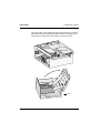
1
BEETLE
BEETLE /M
Modular POS System
User Guide
BEETLE /M
User Guide
Edition April 2000
Pentium© is a registered trademark of Intel Corporation
MS-DOS© is a registered trademark of the Microsoft Corporation
BEETLE© is a registered trademark of Wincor Nixdorf GmbH
Copyright © Wincor Nixdorf GmbH & Co. KG, 1999
The reproduction, transmission or use of this document or its contents is not permitted
without express authority.
Offenders will be liable for damages.
All rights, including rights created by patent grant or registration of a utility model or design, are
reserved.
Delivery subject to availability; technical modifications possible.
Contents
Manufacturer´s Certification .................................................................... 1
Tested Safety .............................................................................................. 1
FCC-Class A Declaration ............................................................................ 1
Important notes ........................................................................................... 2
Introduction ............................................................................................... 4
About this manual........................................................................................ 5
Care of the BEETLE /M............................................................................... 6
Recycling the BEETLE /M........................................................................... 7
Spare Parts ................................................................................................. 8
BEETLE /M - the individual POS System ................................................ 9
Overview ..................................................................................................... 9
BEETLE /M Peripherals.......................................................................... 10
BEETLE /M in a network......................................................................... 11
Before switching on the System................................................................ 12
Unpacking and checking the System ..................................................... 12
Setting up the device .............................................................................. 12
Vertically Installation ............................................................................... 13
Cabling of the BEETLE /M ...................................................................... 14
Securing the data cable .......................................................................... 15
Mounting the cable cover........................................................................ 16
Connecting to the mains power supply................................................... 17
Disconnecting cables .............................................................................. 18
Basic settings .......................................................................................... 18
Adjusting the loudspeaker ...................................................................... 19
Light emitting diode (LED) ...................................................................... 19
Connecting peripherals ............................................................................. 20
Keyboard (KYBD) ................................................................................... 21
Cash drawer (CASHDRW) ..................................................................... 21
Scanners and scales (COM1 - COM4*) ................................................. 22
Customer display (COM2* or COM4*).................................................... 23
Cashier display (COM3*) ........................................................................ 23
Monitor ................................................................................................... 24
Connecting standard PC peripherals (COM1)........................................ 24
Network ...................................................................................................24
Modular printers (V24, LPT1 / 24V, max. 2A) .........................................25
BEETLE /M - the components ................................................................27
Overview ....................................................................................................27
The BEETLE card......................................................................................29
The various card types ............................................................................30
SRAM Card ..........................................................................................30
MASK ROM Card.................................................................................30
OTPROM Card ....................................................................................30
FLASH EPROM Card ..........................................................................31
Inserting the BEETLE Card .....................................................................31
Removing the BEETLE card ...................................................................32
Write protection for SRAM cards.............................................................32
Changing the battery for SRAM cards ....................................................33
Floppy disk drive........................................................................................35
General....................................................................................................35
Inserting a disk ........................................................................................36
Removing a disk ......................................................................................36
CD ROM drive ...........................................................................................37
CPU ...........................................................................................................38
General....................................................................................................38
Interfaces.................................................................................................39
Loudspeaker............................................................................................39
Nonvolatile RAM (NV-RAM)....................................................................39
Dynamic RAM .........................................................................................40
Connection options..................................................................................40
Connecting a hard disk ........................................................................40
Free slots .............................................................................................40
Additional slot on the CPU ...................................................................40
Power pack ................................................................................................41
Battery.......................................................................................................42
Changing the battery ...............................................................................43
Security against power failure ................................................................45
Changing the BEETLE /M battery ...........................................................46
Configuration variants ............................................................................48
Submodules for the CPU...........................................................................48
ASYNC controller ....................................................................................48
SVGA controller.......................................................................................48
LAN controller, SVGA/LAN controller ....................................................48
Installing the submodules........................................................................49
AT plug-in cards ....................................................................................... 52
BEETLE inhouse controller..................................................................... 52
PCMCIA controller .................................................................................. 52
SNIkey controller..................................................................................... 52
Installing an expansion card .................................................................. 53
Change of the harddisk ............................................................................. 55
Software ................................................................................................... 57
Operating system ...................................................................................... 57
Retail device interface............................................................................... 57
Application programs ................................................................................ 58
Retail presentation manager ..................................................................... 58
Retail transaction manager ....................................................................... 58
High frequency table ................................................................................. 58
Hash file access method ........................................................................... 58
Starting up the system ........................................................................... 59
Start and runup behaviour......................................................................... 59
BIOS setup ............................................................................................... 63
Appendix .................................................................................................. 77
Technical data for the BEETLE /M............................................................ 77
CPU ........................................................................................................... 78
ASYNC controller ...................................................................................... 79
SVGA controller......................................................................................... 79
LAN controller (Ethernet) .......................................................................... 80
SVGA/LAN controller ................................................................................ 80
What to do if... ........................................................................................... 81
The Operating Display remains dark ...................................................... 81
Internal Power Supply Surcharge ........................................................... 81
Screen remains black ............................................................................. 81
Incorrect Time and Date ......................................................................... 82
The configuration label ............................................................................. 83
Power On Self Test (POST)...................................................................... 84
MS-DOS Critical Errors........................................................................... 85
Output of MS-DOS system error messages ............................................. 86
POST extended error messages ............................................................ 87
Phoenix BIOS POST and Start Messages ............................................. 88
Additional messages............................................................................... 91
Glossary .................................................................................................... 92
Abbreviations............................................................................................. 94
Manufacturer´s Certification
The device complies with the requirements of the EEC
directive 89/336/EEC with regard to ‘Electromagnetic
compatibilily" and 73/23/EEC “Low Voltage Directive”.
Therefore, you will find the CE mark on the device or packaging.
Tested Safety
The POS system has been provided with the
symbol for “Tested Safety”.
In addition, the BEETLE has received the UL
symbol and cUL symbol.
FCC-Class A Declaration
This equipment has been tested and found to comply with the limits for
a Class A digital device, pursuant to part 15 of the FCC Rules. These
limits are designed to provide reasonable protection against harmful
interference when the equipment is operated in a commercial
environment.
This equipment generates, uses, and can radiate radio frequency
energy and, if not installed and used in accordance with the instruction
manual, may cause harmful inteference to radio communications.
GB - 1
Important notes
Operation of this equipment in a residential area is likely to cause
harmful interference in which case the user will be required to correct
the interference at his own expense.
Le présent appareil numérique ne fait pas de bruits radioélectriques
dépassant les limites applicable aus appareils numériques de la “Class
A” prescrites dans le Règlement sur le brouillage radioélectrique édicte
par le ministère des Communications du Canada.Note on the laser
lf your device is equipped with a CD ROM drive, the following condition
applies:
Important notes
The CD ROM drive contains a light-emitting diode (LED), classified
according to IEC 825-1:1993:LASER CLASS 1; it must not be opened.
Important notes
The modular POS system BEETLE /M conforms to the current safety
standards for data processing equipment.
GB - 2
❚
If this device is taken from a cold environment into the operating
room, moisture condensation may form. The device must be
absolutely dry before being put into service; an acclimatization
period of at least two hours must therefore be observed.
❚
This device is equipped with a safety-tested power cable and may
be connected only to a prescribed grounded-contact power socket.
❚
When setting up the device, ensure that the power socket on the
device and the grounded-contact power socket are easily
accessible.
❚
To disconnect the device from the supply voltage completely,
switch off the device und disconnect the power plug.
❚
Ensure that no foreign objects (c.g. office clips) find their way into
the device, as this may lead to electric shocks or short-circuits.
❚
In order to ensure that the device is well ventilated and to prevent
overheating, do not obstruct the ventilation slots on your device.
Important notes
❚
Never plug in or unplug data communication lines during
thunderstorms.
❚
Protect devices from vibrations, dust, moisture and heat.
❚
Always dispose of used parts, such as batteries, in an
environmentally safe manner.
❚
The lithium battery must be disposed of in accordance with local
regulations for special waste.
❚
In emergencies (e.g. damaged housing or damaged power cable,
penetration by liquids or foreign bodies), the device must be
switched off immediately, the power plug disconnected and the
Customer Service of Wincor Nixdorf (WN) or your dealer must be
notified.
❚
The device may only be repaired by authorized qualified
personnel. Unauthorized opening of the device and inexpertly
carried-out repairs may not only seriously jeopardize the safety of
the user, but also cancel all warranty and liability agreements.
❚
Your BEETLE POS system is the result of modern technical
innovation. So please see for according structural and technical
surroundings to guarantee a faultless and efficient work of your
BEETLE.
Important notes
Therefore, you should connect your BEETLE or other IT-devices
only to power supply systems with separately guided protective
earth conductor (PE). This kind of electricity system is known as
TN-S network. Do not use PEN conductors!
Please also observe the recommendations of the norm DIN VDE
0100, Part 540, Appendix C2 as well as EN50174-2, §5.4.3.
Thus you can help to avoid possible malfunctions.
GB - 3
Introduction
Introduction
The BEETLE /M is the compact, powerful and economical basis for
your POS system.
The BEETLE /M conforms to the PC/AT industry standard. Powerful
Pentium class processors ensure a quick processing of all operations.
You can connect a variety of different peripheral devices to your
BEETLE /M and even the choice of the software is not limited to a
certain product.
Optional the BEETLE /M can be equipped with a hard disk and a CD
ROM drive as further storage mediums.
This provides you with a considerable degree of flexibility when
arranging the layout of your POS system.
The BEETLE can also be connected to a network once an appropriate
network card has been installed.
In the event of a mains voltage failure, the version with battery and
corresponding software enable you to save the data by means of a
controlled program shutdown.
Introduction
GB - 4
Whatever configuration you need: Wincor Nixdorf (WN) offers the right
solution. So, whenever you want to expand your BEETLE /M, please
contact your WN branch office or your dealer.
Introduction
About this manual
About this manual
This manual describes the modular POS system BEETLE /M with a
Pentium type processor.
This documentation is intended to help you work with the POS system
and to serve as a reference work. The detailed table of contents helps
you find the desired information quickly and easily.
The first section describes
■
everything you need to do before switching on the POS system
and
■
how to connect peripherals to the BEETLE /M.
The second section contains
■
a brief overview of the components of your BEETLE POS system.
Here, you will also find a detailed description of recurring actions,
for example, how to use the disks.
The third selection provides
■
a brief overview of the software implemented in the modular
system BEETLE /M.
The fourth section explains
■
the procedure for system starting and setup. This section requires
technical knowledge.
About this manual
GB - 5
About this manual
Introduction
The Appendix
■
contains the most important technical data, a list of possible error
messages, the installation of plug-in cards, a glossary and a list of
abbreviations.
Notes in the manual are marked by this symbol.
This symbol is used for warnings.
The type and scope of application programs depend on the customer’s
own selection; therefore, with the exception of the Setup program and
a brief description of the most important WN programs, software will
not be discussed further in this manual.
Separate manuals are included in the scope of the connectable
peripherals. For this reason, a more detailed description of these
devices will not be provided here. For more information, see the
relevant manuals.
Care of the BEETLE /M
Clean your BEETLE/M at regular intervals with a suitable
plastic-surface cleaner which can be ordered from Wincor Nixdorf.
Make sure that the power plug is disconnected and that no liquid
finds its way into the device.
GB - 6
Introduction
Recycling
Recycling the BEETLE /M
Environmental protection
does not begin when it
comes time to dispose of
the BEETLE; it begins with
the manufacturer. This
product was designed
according to our internal
norm “Environmental
conscious product design
and development”.
Recycling
The modular BEETLE /M POS System is manufactured without the
use of CFCs und CCHS and is produced mainly from reusable
components and materials.
The processed plastics can, for the most part, be recycled. Even the
precious metals can be recovered, thus saving energy und costly raw
materials.
Please do not stick labels onto plastic case parts. This would help us to
re-use components and material.
You can protect our environment by only switching on your equipment
when it is actually needed. If possible, even avoid the stand-by-mode
as this wastes energy, too. Also switch your equipment off when you
take a longer break or finish your work.
At this time, there are still some parts that are not reusable. Wincor
Nixdorf guarantees the environmentally safe disposal of these parts in
a Recycling Center, which is certified pursuant to ISO 9001.
So don’t simply throw your BEETLE POS system on the scrap heap
when it has served its time, but take advantage of the environmentally
smart, up-to-date recycling methods!
Please contact your competent branch or the Recycling Center
Paderborn (for european countries) for information on how to return
Recycling
GB - 7
Spare Parts
Introduction
and re-use devices and disposible materials under the following fax
number:
Fax: +49 (0) 5251 8-26709
We look forward to your fax.
Spare Parts
All spare parts that can be ordered with their Order-Numbers are
registered on a label inside the cover of the BEETLE /M.
Spare Parts
GB - 8
BEETLE /M - the individual POS System
Overview
You can connect a variety of peripherals to your modular POS system
BEETLE /M and thus implement a wide range of expansion stages. You
can
■
connect a two or four-line alphanumeric customer display and a
four line cashier display. Alternatively you can connect Flat
screens, such as BA69 (VGA/4), BA70 (b/w) or BA71 and BA72
(color),
■
use various types of scanners such as distance, touch or
stationary scanners,
■
use scales and scanner scales (please take into account the
official certification regulations),
■
connect various printers,
■
use different types of cash drawers,
■
install the POS workplace SNIkey and different screen displays,
■
integrate the BEETLE /M in a network after installing a LAN board
and
■
upgrade the BEETLE /M, since it can accommodate one PCI- and
alternatively another PCI card or a ISA card.
This means that the BEETLE /M can meet your requirements at all
times, without having to exchange the complete system for a new one,
thus saving you time and money.
GB - 9
BEETLE /M Peripherals
The illustration below shows you how your modular POS system can
grow - from a scanner to integration in a network.
BEETLE /M Peripherals
BEETLE /M Peripherals
Scanners
Customer displays
Monitors
BA69 (VGA/4)
Flatscreen
displays
Cashier displays
Keyboards
Cash drawers
Scales
Printers
GB - 10
The individual POS System
BEETLE /M in a network
BEETLE /M in a network
The individual POS System
BEETLE /M in a network
Ethernet
10 Base T
Server
Ethernet
10 Base T
GB - 11
Before switching an the System
The individual POS System
Before switching on the System
Unpacking and checking the System
Unpack the parts and check to see whether the delivery matches the
information on the delivery note.
The carton contains the basic unit and a country-specific accessories
kit. The basic unit can also be equipped with a network board, floppy
drive, hard disk or a VGA board, or a combination of these components.
If damage has occurred during shipping or if the package contents do
not match the delivery note, promptly inform your Wincor Nixdorf sales
outlet.
Transport the device only in its original packaging
(to protect it against impact and shock).
Setting up the device
Set up the BEETLE /M POS system where it will not be exposed to
extreme environmental conditions. Protect the device from vibrations,
dust, moisture, heat and strong magnetic fields.
Make sure that the side ventilation slots on the
BEETLE /M POS system are not obstructed in
order to ensure that the device has sufficient
ventilation.
Before switching an the System
GB - 12
The individual POS System
Before switching an the System
Vertically Installation
The BEETLE/ M is specified for a horizontal mounting. Observe the
following if the system still is to be mounted vertically:
You will find a drill at the bottom side, so that you can
suspend the BEETLE /M with a screw. To do so, mount two
additional angles at the requested wall so that the BEETLE
can rest upon evenly.
Hole
A closed area made of non flammable material (e.g.
concrete or metal) must be located under the vertically
mounted BEETLE /M.
Mount the device in such a way that the ventilator faces
upwards. That is the side with the lesser number of
ventilation slots.
Make sure that the angles do not cover the ventilation slots.
The following minimum clearances (also in horizontal
position) must be provided in free convection to ensure
sufficient ventilation:
horizontal placement: left side: 60 mm, right side: 100 mm
vertical placement: upwards: 100 mm, downwards: 60 mm
GB - 13
Cabling of the BEETLE
The individual POS System
Cabling of the BEETLE /M
Cabling of the BEETLE
Follow the steps below in the order given when installing devices:
Make sure that the power switch on the front of the housing
is set to OFF, i.e. that it visibly protrudes. You may have to
open the slide in order to do this (see figure on page
GB - 17).
The cable cover must be removed, if present.
Plug one end of the power cable into the power cord
receptacle on the BEETLE /M.
Plug the other end of the power cable into a
grounded-contact power socket.
Plug in and secure the data cable.
Always make sure that the system is switched off when you
do cabling works.
GB - 14
The individual POS System
Cabling of the BEETLE
Securing the data cable
Secure interface
connectors with
knurled screws
manually.
The interface
connectors
screws made of
metal can be
secured with a
screwdriver.
Screws made of
plastic must be
secured manually
only.
Mini-DIN plugs
lock in when you
insert them.
Check the lock by
slightly pulling the
cable. Maybe you
will have to lock
the plug by
slightly pushing
the cable.
Replace the cable cover after the cables have been mounted (see next
page).
GB - 15
Mounting the cable cover
The individual POS System
Mounting the cable cover
The scope of supply of your BEETLE /M includes a cable cover. Before
mounting the device, you should first remove the cable openings where
necessary. This depends on the cables which you wish to lay.
Tools are not required as the plastic parts can be removed by hand.
In order to mount the cable cover, insert it in the guides marked with
arrows in the figure below. In doing so, ensure that the cable cover
does not fit askew.
Mounting the cable cover
GB - 16
The individual POS System
Power supply
Connecting to the mains power supply
All devices belonging to the modular BEETLE /M POS system that
have a separate power cable must be connected to the same electric
circuit.
Ensure that the power switch on the POS terminal housing
is switched off.
Make sure that all data cables on the system unit and
peripherals are connected correctly.
Plug all power cables belonging to the BEETLE and the
peripherals into the grounded-contact power sockets.
ON/OFF switch
Lock
Slide
Cover
ON button
You can now
switch on the
BEETLE /M by
means of the
switch on the
front of the
housing. You
may have to
unlock the slide
and move it to the
left.
Power supply
ON button
The power pack can be connected to all standard
power supply networks. The unit adjusts automatically to the respective voltage. A fan
provides the required ventilation. The maximum
output of the power pack is 135 W.
GB - 17
Disconnecting cables
The individual POS System
Disconnecting cables
Disconnecting cables
Never unplug a cable by pulling on the cable itself; always take hold of
the actual plug. Follow the procedure below when disconnecting cables:
Turn off all power and equipment switches.
Remove the cable cover.
Unplug all data communication cables from the sockets of
the data networks.
Unplug all power plugs from the grounded-contact power
sockets.
Unplug all cables from the devices.
With MINI-DIN plugs, the plug
remains inserted until released.
Pull the plastic covering from
the connecting socket with your
thumb. The lock is released.
The metal of the plug is visible.
Now remove the cable from the connecting socket.
Basic settings
Ex works, the BEETLE /M is configured to your order. Your
configuration must be subsequently adapted to support supplementary
devices such as scanners. For more information, contact the WN
branch office responsible for your area.
GB - 18
The individual POS System
Adjusting the loudspeaker
Adjusting the loudspeaker
Adjusting the loudspeaker
You can set the volume as desired by means of the volume control on
the back of the POS terminal housing.
Light emitting diode (LED)
The right LED (yellow) below the ON/OFF switch lights up while the
hard disk is beeing accessed. The left LED (green) lights when the
BEETLE/ M is switched on.
GB - 19
Connecting peripherals
The individual POS System
Connecting peripherals
Connecting peripherals
The peripherals mentioned here are available as options and are not
part of the basic configuration. A separat manual is provided for each
of the connectable components. For more detailed information, please
consult the relevant documentation.
The figure shows the back panel of the BEETLE/ M with the locations
of the connecting sockets and connecting plugs. If you wish to connect
a monitor, however, you must also have a video board. You can connect
the system to a network via an expansion board.
The interfaces COM7 and COM8 are optional.
CRT and TFT interfaces are used alternatively.
Cover lock
Battery lock
Battery Connector
COM7
COM8
Socket
Mains supply
Rear panel of the BEETLE/ M
GB - 20
The individual POS System
Connecting peripherals
Keyboard (KYBD)
The BEETLE /M has a 6-pin mini-DIN jack for connecting a keyboard.
Make sure that the connector is plugged firmly into the socket to
prevent malfunctioning. Power is supplied to the keyboard via this
socket. If you wish to connect a standard PC keyboard with DIN
connector, you must use a special adapter cable, obtainable from the
WN branch office responsible for your area.
When removing cables with locks, please grip the
cable at the connector housing.
Cash drawer (CASHDRW)
The BEETLE /M has a second 6-pin mini-DIN jack for connecting a
cash drawer. Make sure that the connector is plugged firmly into the
socket to prevent malfunctioning. Power is supplied to the cash drawer
via this socket.
When removing cables with locks, please grip the
cable at the connector housing.
GB - 21
Connecting peripherals
The individual POS System
Scanners and scales (COM1 - COM4*)
Depending on how the system is configured, scanners and scales
without an independent power supply are connected to the COM2*,
COM3* or COM4* serial interface (standard setting COM3). Connect
scales with their own power supply to the COM1 interface. COM1 is
designed as a 9-pin D-sub plug, whereas COM2* - COM4* are 9-pin
D-sub jacks.
Make sure that the scanner connector is plugged securely into the
socket to prevent possible malfunctioning.
If scales which are not supplied by Wincor Nixdorf are
connected to the BEETLE /M, you must obtain an WN
licence for the driver software.
If COM2 is equipped with a connector, the interface does not carry a
current.
GB - 22
The individual POS System
Connecting peripherals
Customer display (COM2* or COM4*)
With the BEETLE /M, and depending on how the system is configured,
the customer display is connected to either the COM2* or COM4*
serial interface. The interface connection is a 9-pin D-sub jack. Make
sure that the connector for the customer display is screwed firmly to
the socket to prevent possible malfunctioning. Power is supplied via
this jack.
If COM2 is equipped with a connector, this interface does not carry a
current.
Cashier display (COM3*)
Connect the cashier display to the serial interface COM3*. This port is
a 9-pin D-sub jack.
Make sure that the connector for the cashier display is screwed firmly
to the socket to prevent possible malfunctioning. Power is supplied via
this jack.
GB - 23
Connecting peripherals
The individual POS System
Monitor
If a VGA board is installed, you can connect a monitor to the
BEETLE /M via the 15-pin D-sub jack on the VGA board. Power is
supplied to the monitor via the rubber connector on the BEETLE /M,
located on the back of the housing.
Connecting standard PC peripherals (COM1)
You can connect supplementary standard peripherals to the
BEETLE /M via the COM1 serial interface.
Make sure that all supplementary devices have been tested for RFI
suppression pursuant to the legal requirements of your country.
Network
If a network board is installed, the system can be connected to a
network (LAN) from the POS terminal back panel. If a LAN board is not
installed, this location on the back panel is closed by a dummy cover
(see also Configuration variants).
GB - 24
The individual POS System
Connecting peripherals
Modular printers (V24, LPT1 / 24V, max. 2A)
The standard parallel interface LPT1 is intended for connecting a
printer.
Appropriate POS printers can also be connected via the low-voltage
jack 24V, max. 2A. A connecting cable with a HOSIDEN plug is
required for this. Connect only cable to the 24V connector which are
marked with DP-1 or DP-2 !
GB - 25
Connecting peripherals
GB - 26
The individual POS System
BEETLE /M - the components
Overview
The following figure shows the outside of the BEETLE /M.
Lock
Floppy disk drive
Slide
Cover On/Off switch
Ventilation slots
CD-ROM-drive
LEDs
On/Off switch
GB - 27
Overview
BEETLE /M - the components
BEETLE /M - the components
Overview
The figure below shows the inside of the BEETLE /M.
Power pack
Hard disk
Submodule
Ventilator for
Pentium-Processor
GB - 28
Floppy disk drive
BEETLE /M - the components
Overview
GB - 29
BEETLE components
BEETLE Card
The BEETLE card
BEETLE components
BEETLE Card
The BEETLE card, which is a credit-card-sized memory card,
optionally provides the BEETLE POS system with a storage medium
characterized by a number of advantages, including:
■
High storage capacity
■
Small size, thus taking up less space
■
Mechanical robustness
■
High data security (not magnetically sensitive)
■
Relative insensitivity to moisture and heat
■
Rapid data access, since it has no mechanically moving parts
BEETLE cards can be used for a variety of applications, such as:
■
Loading programs
■
Saving data (e.g. daily sales figures)
■
Access control (“electronic key”)
There is already an internationally valid standard for memory cards
(PCMCIA/JEIDA). This means that you can use cards of the same type
made by different manufacturers.
The BEETLE allows you to use cards with a storage capacity of up to
64 MB.
GB - 29
BEETLE Card
BEETLE components
The various card types
You can use the following memory cards as standard BEETLE Cards:
SRAM card
MASK ROM card
OTPROM card
FLASH EPROM card
Readable and writeable
Readable
Readable
Deletable, writeable, readable)
The following briefly describes the characteristics of the useable cards.
SRAM Card
This card type can be read and written to by the system any number of
times. You can write protect the SRAM card to prevent accidental
overwriting of the stored data.
An integral battery is used for the retention of data. The length of time
data is retained depends on the life of the battery, which in turn
depends on the storage capacity of the card used.
MASK ROM Card
The data contents of this card are determined by the manufacturer of
its memory chips and cannot be subsequently modified.
OTPROM Card
Data can be written to this card once and can then no longer be
modified. The card is written to in special memory disk drives only.
GB - 30
BEETLE components
BEETLE Card
FLASH EPROM Card
Data can be written to and erased from these cards electronically.
Consequently, they are ideal for data subject to frequent modification.
The cards can be written to in special memory card drives only. FLASH
EPROM cards do not require batteries for data retention.
If you have any further questions about BEETLE cards,
contact the WN branch office responsible for your area.
Inserting the BEETLE Card
Insert the card, connector-end first, in the slot for the BEETLE card.
The card has been correctly inserted if the black ejection button next to
the slot has popped out.
GB - 31
BEETLE Card
BEETLE components
Removing the BEETLE card
If necessary, first
unlock the cover.
Then press the
black ejection
button next to the
slot. You can now
remove the card.
Write protection for SRAM cards
WP
GB - 32
BATTERY HOLDER
LOCK
To write protect
the SRAM-type
BEETLE card,
slide the lock
shown in the
illustration to the
WP (write
protection)
position.
BEETLE components
BEETLE Card
Changing the battery for SRAM cards
The illustrations below show you how to change the battery for this
type of BEETLE card.
Changing the battery without losing the stored data is possible
only in the case of memory cards made by certain
manufacturers. For more information, contact the SNI branch
office responsible for your area.
Unlatch the
battery lock
WP
BATTERY HOLDER
LOCK
Remove the
battery holder
and battery from
the BEETLE card
GB - 33
BEETLE Card
BEETLE components
Battery in the
holder. The
battery’s positive
terminal is face
up.
3V
3V
3V
Lift the battery up
and out.
To insert the new battery, follow the steps above in reverse order.
Avoid touching the plus and minus pole at the same time as
this can shorten the service life of the battery. Dispose of used
batteries in an environmentally safe manner.
GB - 34
BEETLE /M - the components
Flopppy disk drive
Floppy disk drive
General
BEETLE /M - the components
The BEETLE /M is equipped with a floppy disk drive for 3.5" disks. The
LED lights up whenever the system accesses the drive.
The disks can be used for a variety of applications, such as:
Loading programs
Saving data (e.g. daily sales figures)
Access control (electronic key)
Flopppy disk drive
The disk can be write protected to protect your data from accidentally
being overwritten. The slide is located at the bottom left of the diskette.
Writing to the disk
is possible.
Writing to the disk
is not possible.
GB - 35
Flopppy disk drive
BEETLE /M - the components
Inserting a disk
Hold the disk so
that the arrow
symbol is at the
top and points
away from you.
Now insert the
disk in the drive
slot provided. The
disk has been
correctly inserted
if the gray
ejection button
has popped out.
Removing a disk
Press the gray ejection button next to the drive slot. You can now
remove the disk.
Never remove the disk while the drive is being
accessed, i.e. when the LED indicator for the drive is
illuminated. Otherwise, you could damage the drive and
the disk.
Floppy disk
Slider
GB - 36
The lockable
slider can be
used to prevent
unauthorized
access to the disk
drive.
BEETLE /M - the components
CD ROM drive
CD ROM drive
The BEETLE /M can be equipped with a CD ROM drive, if you wish so.
The lockable slider prevents unauthorized access to the disk drive.
Open the drive by pressing the ejection button in the middle of the
loading box. You lock it by sliding in the loading box.
CD ROM drive
Lock
Slider
CD ROM drive
GB - 37
CPU
BEETLE /M - the components
CPU
General
The modular POS system BEETLE /M is supplied with a CPU of the
Pentium-class.
CPU
The CPU comprises a specially developed PC board. In addition to the
PC-specific modules and interfaces, this board accommodates a
non-volatile memory (NV-RAM) and an optional VGA controller for
connecting a monitor.
The connecting plate of the board has the sockets for the external
peripherals. The illustration below shows the connector assignments
for the CPUs.
Cover lock
Battery lock
Battery Connector
COM7
COM8
Socket
GB - 38
Mains supply
BEETLE /M - the components
CPU
Interfaces
The COM1 interface of the BEETLE /M is designed for connecting
standard peripherals that have a separate power supply. The COM2*,
COM3* and COM4* are provided for connecting special POS
peripherals that do not have a separate power supply, for example a
scanner or a display. The BEETLE /M is also equipped with a parallel
interface and a DC24 /2A power supply interface for connecting POS
printers as well as two mini DIN jacks for connecting the keyboard and
cash drawer.
Connect only devices approved by Wincor Nixdorf to
your BEETLE /M. If you have any questions, contact the
WN branch office responsible for your area.
Loudspeaker
A loudspeaker is connected to the CPU. The volume of the
loudspeaker can be set using the rotary knob on the rear panel of the
modular POS system. The loudspeaker is located behind the left-hand
side of the rear panel.
Nonvolatile RAM (NV-RAM)
This memory chip can be used to store important data - such as sales
totals or diagnostic entries - by means of the appropriate software and
independently of the power supply. The data is retained for more than
five years.
The NV-RAM is standard only in systems with the operating system
MS-DOS.
GB - 39
CPU
BEETLE /M - the components
Dynamic RAM
The operating system and the application require this memory while
they are running. The following types are available:
Pentium class CPU (with PS2 SIMM)
8 = 2*4 MB (Default)
32 = 2*16 MB
16 = 2*8 MB
64 = 2*32 MB
Connection options
The CPU is designed so that expansions are possible at any time, as
desired.
Connecting a hard disk
One hard disk can be connected to the CPU. It is used to store the
operating system and POS-specific software. It can also be used for
the long-term storage of the electronic journal. 3.5" hard disks can be
used for this purpose. These disks have a 16-bit IDE (integrated drive
electronics) AT-bus system interface and an integrated controller. For
the default settings and technical data for the hard disks, see the
configuration label.
Free slots
The system is fitted with two ISA or one ISA and one PCI slots for two
half-lenght AT-expansion cards.
Additional slot on the CPU
The CPU is equipped with an additional slot which can be used to
connect one of the available controllers (SVGA, LAN, SVGA/LAN,
ASYNC), if required.
GB - 40
BEETLE /M - the components
Power pack
Power pack
Power pack
The power pack can be connected to all conventional power supply
networks. It automatically adjusts itself to the particular voltage and is
fan-cooled. The power output of the power pack is maximum 135 W.
The power pack must be removed or replaced by
authorized qualified personnel only.
The power cord receptacle and the power output socket for the monitor
are located on the back of the BEETLE /M. The power switch is located
on the front of the device.
The power switch can
be protected from
access using the
lockable slide.
Lock
Slider ON/OFF Switch
GB - 41
Battery
BEETLE /M - the components
Battery
Battery
The battery bridges any power failures and allows a controlled
shutdown of the POS programm by means of the appropriate software
(see “Security in the event of power failure”).
Battery charging time is approx. 8 hours after initial
startup. The battery is charged only while the system is
switched on.
The table below provides an overview of how long the BEETLE /M is
supplied with battery power in the event of a power failure (with the
battery fully charged).
Duration of
power supply
Power output
Operation
0, 5 minutes
Full load
(max. 90 W)
with supply of external
peripherals (e.g. 24V printer)
1, 5 minutes
Medium load
(approx. 70 W)
e. g. printer running
10 minutes
Low load (30 W)
e. g. device switched on
Peripherals connected to the power output socket of the
POS terminal are not powered during a power failure.
GB - 42
BEETLE /M - the components
Battery
Changing the battery
All batteries have a limited service life. In order to prevent any loss of
data, we recommend that you charge the battery at least every five
years.
Make sure that the device is switched off and the power
plug is disconnected.
Remove the cable cover at the backside of the housing by pulling the
cable cover upwards out of the guide. Then press the white button (1).
While holding down the button, push the battery plate to the right side
(2) and pull it backwards (3).
Then loosen the connector (4).
4
3
1
3
2
3
Use only batteries approved by Wincor Nixdorf. Always
dispose of batteries in an environmentally safe manner.
GB - 43
Battery
BEETLE /M - the components
Change the battery which is placed in the punched tin.
Connect the plug to the jack (1) and reinstall the battery plate with the
new battery at the backside of the BEETLE /M.
Insert the battery plate into the slots (2) and move it to the left (3) until
the lock snaps in.
1
2
2
3
GB - 44
2
BEETLE /M - the components
Battery
Security against power failure
If the battery is used, the BEETLE /M system has another important
feature.
When the power fails, the system remains fully functional for a short
period of time. The power needed for further operation is supplied by
the battery.
Because operation is maintained with the aid of the battery, the
application program can be terminated correctly.
The power failure is reported to the application program by means of
the retail device interface (see chapter Software). The application
program then terminates the program correctly by, for example, closing
open files and writing important information to the non-volatile memory.
The termination of these actions is reported by means of the retail
device interface. This causes the system to be disconnected, which
also prevents the battery from being discharged unnecessarily.
Peripherals connected to the power output jack of the
POS system are not powered during a power failure.
GB - 45
Changing the battery
BEETLE /M - the components
Changing the BEETLE /M battery
Changing the battery
The BEETLE /M is equipped on the CPU board with a lithium battery to
ensure the retention of data, the time and the setup parameters. The
battery should be changed approximately every five years.
When inserting the new battery, make sure the polarity
is correct. This is visibly marked on the socket. Incorrect
replacement may lead to the danger of explosion.
The battery is located in a socket in the CPU. To gain access to the
battery, proceed as described in the chapter entitled “Installing the
submodules” until you lift up the carrier.
Pentium-class - board
The lithium battery must be replaced only by identical
batteries or types recommended by the manufacturer.
The lithium battery must be disposed of in accordance
with local regulations for special waste.
The setup parameters must be reset each time the battery is changed
(see chapter Setup).
GB - 46
BEETLE /M - the components
Changing the battery
The lithium battery must be replaced by the end user
only by identical batteries or types recommended by
Wincor Nixdorf GmbH.
You can return the used batteries to your Wincor Nixdorf
sales outlet.
Batteries containing harmful substances are marked
accordingly. The chemical denotations are as follows:
CD = Cadmium; Pb = Lead, Li = Lithium.
This symbol on a battery tells you that batteries
containing harmful substances must not be disposed of
as household waste. Within the European Union you are
legally bound to return these batteries to a Wincor
Nixdorf sales outlet!
The setup parameters must be reset each time the
battery is changed (see chapter Setup).
GB - 47
Submodules
Configuration variants
Configuration variants
Submodules for the CPU
Configuration variants
Submodules
Various controllers can be plugged in on the CPU. The following is a
brief description of the available options:
ASYNC controller
This RS232 interface card can be used as an additional, live serial
interface for connecting various peripherals.
When connecting an ASYNC controller, ensure that the
total current consumption of all of the live serial
interfaces does not exceed 900 mA.
SVGA controller
The SVGA controller can be used to connect a monitor.
LAN controller, SVGA/LAN controller
This controller can be used to incorporate the BEETLE /M in an
Ethernet network (10 Base T), the combined SVGA/LAN controller
allows you to connect a monitor and to integrate your BEETLE /M into
a network at the same time.
GB - 48
Configuration variants
Submodules
Installing the submodules
First ensure that the device is switched off and that the power
connector is disconnected.
Remove the battery plate (see page 43).
Lift up the latch (see arrows) and push the housing with the latch
forward.
Then you can pull up the housing.
GB - 49
Submodules
Configuration variants
Lift up the carrier of the harddisk and the floppy disk drive by loosening
the knurled screw (see drawing) manually or with a screwdriver. Then
pull the carrier forward to the stop and lift it up to the front side.
Hard disk
Knurled screw
Front
GB - 50
Configuration variants
Submodules
Remove the respective metal cover at the backside of your
BEETLE /M by removing the screws with a socket wrench. Then bring
the socket through the recess of the housing and plug in the card (see
drawing). Attach the socket using the screws that you removed before.
Plug-in card
GB - 51
AT plug-in cards
Configuration variants
AT plug-in cards
All standard ISA and PCI cards can be used in the BEETLE /M.
AT plug-in cards
BEETLE inhouse controller
The BEETLE Inhouse Controller (BIC) is a ISA card for BEETLE POS
systems. The board ensures that BEETLE systems can be integrated
in existing installations in inhouse networks.
The card is installed in a free AT slot in the POS housing.
If you would like further details on this expansion card, please contact
your dealer or your local WN branch.
PCMCIA controller
Using an appropriate PCMCIA controller, you can use various storage
media, such as FLASH memory card and I/O cards, magnetic cards of
Type 1 EXT, Type II EXT and Type III, and ATA removable disks.
If you want to know more about PCMCIA controllers, contact your
dealer or your WN branch.
SNIkey controller
The SNIkey is a confortable input/output device for BEETLE POS
systems.
Once you have installed an SNIkey controller, you can connect an
SNIkey to the BEETLE /M.
If you want to know more about the SNIkey, contact your dealer or your
WN branch.
GB - 52
Configuration variants
AT plug-in cards
Installing an expansion card
First ensure that the device is switched off and that the power
connector is disconnected.
Please proceed as described in the section “Installing an expansion
card”.
After having pulled forward the carrier of the hard disk and floppy disk
there is an easy access to the AT slots. Now remove the metal cover at
the housing by squeezing out one of the clambs (see picture).
You always should use the upper slot first.
This slot is - depending on the configuration reserved for a PCI-Card.
clamb
First check whether the jumpers (if present) of the card are set
correctly to avoid internal system conflicts. The correct setting for the
jumpers can be found in the documentation for the plug-in card. Then
slide the expansion card into the slot provided. Ensure that the card
establishes contact with the terminal strip.
Secure the card by tightening it with the clamb that you have removed
before (the pin of the clamb has to be put into the boring of the card).
GB - 53
AT plug-in cards
Configuration variants
Following this, mount the POS housing again. The mains connector
can now be reconnected and the device switched on.
Expansion cards with electrostatically sensitive devices
(ESD) can be marked with this sticker.
When you handle boards fitted with ESDs (electronical components),
you must observe the following points under all circumstances:
GB - 54
■
You must always discharge yourself (e. g. by touching a grounded
object) before working with boards containing ESDs.
■
The equipment and tools you use must be free of static charges.
■
Pull out the power plug before inserting or pulling out boards containing ESDs.
■
Always hold boards with ESDs by their edges.
■
Never touch pins or conductors on boards fitted with ESDs.
Configuration variants
Change of the harddisk
Change of the harddisk
Change of the harddisk
To change the hard disk open your BEETLE /M as described in the
chapter “Installing the submodules”. Pull out the connectors (1) as
shown in the picture below.
Hard disk
1
Now push the button (see picture below) and take off the hard disk.
Then flap the carrier back so that you can install the new hard disk.
Just put it on the guide rail and push it back until it snaps in. Plug in
the connectors again.
GB - 55
Change of the harddisk
GB - 56
Configuration variants
Software
This chapter provides a brief overview of the operating system and a
series of programs developed by Wincor Nixdorf GmbH to enable your
BEETLE /M to operate efficiently. More detailed information can be
found in the individual documents for these programs.
Operating system
The BEETLE /M runs under the MS-DOS operating system that was
specially expanded for POS applications.
This makes it possible, for example, to display all system messages on
the cashier display. These messages are appropriately adapted to the
format of the cashier display.
Retail device interface
The retail device interface (RDI) is a uniform C programming interface
for the BEETLE /M.
This interface provides the application programmer with a simple
means of programming retail-specific applications and devices.
GB - 57
Software
Application programs
Software
Application programs are available for the BEETLE /M that meet
retail-specific requirements. For more information, contact the Wincor
Nixdorf branch office responsible for your area.
Retail presentation manager
The retail presentation manager (RPM) is provided as a uniform tool
(MS-DOS and UNIX) for input and output format specification. The
RPM significantly reduces the development outlay for POS applications.
Retail transaction manager
The retail transaction manager (RTM) forms the link between the POS
application and the operating system. The RTM allows the accessing of
shared data, including price lookup and the maintenance of transaction
files.
High frequency table
The price look ups (PLU) in the retail area are performed using the
High Frequency Table (HFT). The HFT provides functional libraries with
uniform interfaces for this purpose.
Hash file access method
Similar to the HFT, the Hash File Access Method (HSF) is primarily
used for price look ups. The extensive article data on the mass storage
can be managed with HSF. To this effect, the article file is specially
structured when it is created. This structure, in conjunction with the
access method for “hash” files, provides particularly short search times.
GB - 58
Software
GB - 59
Starting up the system
The configuration label shows you the equipment included in your
modular BEETLE /M POS system. A sample is contained in the
Appendix. The label is located on the underside of the BEETLE /M.
The data specified there are required for entering the setup parameters
(see Setup).
Start and runup behaviour
After installing the BEETLE /M, switch on the POS system using the
power switch on the front panel.
The system first performs an automatic self-test to test its basic
functions.
For example, you may see the following message (irrespective of
processor type) on the four-line cashier display or on the monitor:
WN ID xx/xx Date
xx/xx is the place holder of the BIOS version number
The system then determines the medium from which the operating
system and POS application are to be booted. Each medium is
assigned a logical drive according to the configuration of your
BEETLE /M.
GB - 59
Start and runup behaviour
Starting up the system
The following media can be assigned a drive:
Starting up the system
Start and runup behaviour
❚
Disk
❚
BEETLE card
❚
Network
❚
Hard disk
The logical drives are designated A:, B:, C: and D:.
If the system is to be booted from disk (BEETLE card), this medium
must always be assigned drive A:. It is also possible, however, to
assign B: to the disk if you wish to use the card as a pure storage
medium. The network is always assigned to the C: drive during the
runup procedure. The hard disk can be assigned to the C: or D: drive.
The system can only be started from the hard disk if the disk has been
configured as the C: drive.
The modular BEETLE /M POS system can be booted from two drives.
However, please note the following restrictions:
❚
The system can be booted from drives A: and C: only.
❚
The storage medium must be system-boot-capable.
The following priorities apply:
Floppy disk (A:)
BEETLE card
High priority
Network (C:)
Medium priority
Hard disk (C:)
Low priority
The POS system always attempts to boot from a disk first if they are
inserted in the respective drive.
GB - 60
Starting up the system
Start and runup behaviour
If the POS system does not find a disk or a BEETLE card in drive A:, it
automatically continues the loading process from drive C:.
If drive A: contains a disk or a BEETLE card on which
the operating system is not stored, the POS system
cannot be booted. In this case, either replace the disk
with one that is system-boot-capable or remove the disk
altogether.
The operating system responds with additional messages on the
cashier display or monitor, as shown in the illustration below.
EMP-NO:
—>
ON/OFF
If the operating system has started up without error, the POS
application software is automatically booted if necessary.
A message is displayed as soon as the BEETLE /M is ready for
operation. For more detailed information, see the description of your
application program.
GB - 61
Start and runup behaviour
GB - 62
Starting up the system
BIOS setup
BIOS setup can be used to restore or reset the configuration parameters
of your BEETLE POS system. The features of your POS system are
displayed on the configuration sticker, which is located on or inside your
BEETLE. A sample sticker is shown on the last page of this chapter.
SETUP contains important basic settings which are necessary to enable
your POS system to operate correctly. These settings include, for
example, the date and time, the assignment of a specific logical drive
name (A: or B:) to the BEETLE card or the floppy disk as well as
parameters for the hard disk.
In case of a faulty configuration you should always run the setup program
to make sure that the POS system works correctly.
You have two options for calling up SETUP:
■
If you are using a standard PC keyboard, press Ctrl, Alt and ESC
simultaneously during the runup phase.
■
SETUP is called up if the keyswitch on the POS keyboard is set to
position 4 during the runup phase.
The default output medium for the BEETLE POS system is the 4-line,
20-column cashier display. If a VGA monitor is connected, information is
output to the monitor.
If no monitor is connected, although an SVGA card is installed,
then the system messages are not visible.
GB - 63
BIOS setup
The menu entries below are intended to serve as examples. If in doubt,
refer to the configuration sticker.
BIOS setup
When SETUP is called, first the Copyright message is output. For
example:
Copyright (C)
WN 2000
Setup Rel. 0.xy
(22/01/98)
The first menu is then displayed. Menus are controlled by pressing the
numeric keys specified in parentheses.
ReBoot with
Help with
Enter Setup with
(7)
(5)
(2)
Pressing the number (2) allows you to set the date and time in a further
menu. (7) reboots the system.
Time
Date
12:34:56
Jan 12 1998
(6)Incr
(2)Next (4)Decr
GB - 64
BIOS setup
In this and subsequent examples, the numeric keys (8), (2), (6), (4), (5)
and (7) have the following meanings:
(8) Prev (Previous)
(2) Next
(6) Incr (Increment)
(4) Decr (Decrement)
(5)
(7)
The cursor is positioned in a previous field or
menu
The cursor is positioned in the next field or
jumps to the next menu
Increments a value in the field
Decrements a value in the field
Calls the help function (key assignment)
Reboots the system
Following the menu for setting the time and date, the menu for the drive
parameters appears.
FD A MEM-Card
FD B Not Installed
(8)Prev (6)Incr
(2)Next (4)Decr
Enter settings for drives A: and B: here.
GB - 65
BIOS setup
The hard disks can be configurated automatically in SETUP. The
necessary parameters are read from the hard disk and stored in the
CMOS RAM. Your POS system offers two interfaces to connect hard
disks and other IDE drives (e.g. CD ROM drive), a PRIMARY port and a
SECONDARY port.
You can connect two drives to each port, a MASTER- and a SLAVE drive.
To use the SECONDARY interface, the Secondary IDE must be set to
“Enable”.
The following masks show an example of possible configurations for a
hard disk that is connected to a PRIMARY SLAVE port.
PRI MASTR AUTO
(8)Prev
(2)Next
(6)Incr
(4)Decr
(2)
A
(4)
PRI SLAVE AUTO
(8)Prev
(2)Next
(4)
(6)Incr
(4)Decr
PRI SLAVE NONE
(8)Prev
(2)Next
PRI SLAVE TYPE 1
(3)List Params
(8)Prev (6)Incr
(2)Next (4)Decr
(6)
(6)Incr
(4)Decr
(2)
(2)
(3)
(...)
(2)
Cyl
Sec
306 Head 4
17
10MB
Any Key to Return
Secondary IDE
Disable (2)
Disable
(8)Prev (6)Incr
(2)Next (4)Decr
Enable (2)
SEC MASTR NONE
(8)Prev
(2)Next
(6)Incr
(4)Decr
(2)
SEC SLAVE NONE
(8)Prev
(2)Next
(6)Incr
(4)Decr
(2)
next
menue
GB - 66
BIOS setup
GB - 67
BIOS setup
GB - 68
BIOS setup
Notes
Note 1
The PIO mode in the mask “HD Transfer Mode”indicates the chosen data
transfer mode for the hard disk. You can set a value between “0" and ”4".
After the automatic readin of the parameters (“HD Get Params ? = Yes”)
you should not change this value . Should any problems occur, you can
only decrement the PIO mode, which will lead to a slower transfer of data.
Note 2
The number of sectors in the mask “Multisector Read” indicates how many
sectors per reading job can maximally be read from the hard disk. You
can set this number to 1, 2, 4, 8 or 16 sectors. After the automatic readin
of the parameters (“HD Get Params ? = Yes”) you should not change this
value. Should any problems occur, you can only decrement the number
of sectors, which will lead to a slower transfer of data.
Note 3
You can choose between the following settings:
- Standard
The operating system MS DOS can only be started from a partition that
is smaller than or equal to 504 MB. The rest can only be used by other
operating systems like e.g. Windows NT or OS/2.
- LBA
With this setting MS DOS can service hard disks up to a capacity of
7,8 Gigabytes (GB).
- Non DOS
Choose this setting if you wish to install the operating system other than
MS-DOS on your BEETLE.
GB - 69
BIOS setup
Please mind the following procedure for handling the hard disk:
Generally you should configurate your hard disk with the setting “AUTO”
(automatical configuration). The BIOS then detects the optimal parameter
settings for your system and these parameters are set. Whenever starting
the system you can read from the monitor the type of installed hard disk in
abbreviated form (Only when “AUTO” is set).
Alternatively you can configurate the hard disk with the setting “USER
TYPE”. With the subfunction “HD Get Params ?” the system tries to read
in the parameters of the hard disk. If this was not succesful you will have
to set all parameters step by step manually, according to the specification
of the hard disk.
Beyond this you can configurate the hard disk with the hard disk types
1 to 39.
If you have connected more than two hard disks you can enable the
Secondary interface by setting “Enable” . You can choose this in the
following mask:
Secondary IDE
Enable
(8)Prev (6)Incr
(2)Next (4)Decr
GB - 70
BIOS setup
A further menu shows you, for example, the memory configuration:
Memory
XMS
(8)Prev
(2)Next
640 KB
7168 KB
XMS stands for extended memory specification (above a memory capacity
of 1 Mb).
It is possible to use the parallel interface LPT1 in standard mode and in
the modes ECP (Enhanced Capability Port) and EPP (Enhanced Parallel
Port). The transfer modes EP and EPP allow a higher data transfer rate
(up to 2MB/s and up to 2,4 MB/s). Please make sure that the peripheral
devices do support these modes.
The choice can be done in the following mask:
LPT1 Mode
Standard
(8)Prev (6)Incr
(2)Next (4)Decr
If you are using printers from WN, please choose the standard
mode.
GB - 71
BIOS setup
With power management you can save energy when your system is off
time. When “No” is set, the CPU operates with maximum speed, i.e. at full
power. If “Yes” is set, the power management facility is enabled.
PowerMan
Yes
(8)Prev (6)Incr
(2)Next (4)Decr
“OFF Timer” switches the CPU to sleep mode (5 - 15 - 60 minutes) after a
specified interval of being idle. In this case the backlighting of the cashier
display is deactivated and a connected monitor is blanked. Make sure that
no screen saver is active!
OFF Timer
(8)Prev (6)Incr
(2)Next (4)Decr
GB - 72
60 Min
BIOS setup
The time interval for deactivating the hard disk can be set separately (OFF
and 60 minutes).
If HD Timer is set to “60 min”, the hard disk is deactivated after reaching
this time (Standby mode).
HD Timer
Off
(8)Prev (6)Incr
(2)Next (4)Decr
In BIOS setup, you can also define whether the opportunity for turn off the
serial interfaces in the sleep mode COM2 to COM4 is selected (COM
Supply On) or not (COMSupply Off) .
*
*
With “COM Supply On” the CPU switches from sleep mode to standard
mode when one of the following interrupts is actuated: IRQ1 (keyboard),
IRQ3 (COM2), IRQ4 (COM1), or IRQ8 (RTC).
COM Supply
Off
(8)Prev (6)Incr
(2)Next (4)Decr
In sleep mode all interrupts are processed ; none are lost.
GB - 73
BIOS setup
The next mask can be used to enter displays (OPERATOR for the cashier
display or VGA for the monitor).
Display OPERATOR
(5) Help
(8)Prev (6)Incr
(2)Next (4)Decr
At the end of SETUP you will see the following mask:
Reset Config Data
No
(8)Prev
(6)Incr
(4)Decr
In this menu you can define whether the configuration data of your POS
system will be initialized when the system is started:
GB - 74
Yes
With the start of the system the old configuration data will be reset.
The plug&play function will detect the current configuration data.
The installed components are initialized by these data. Components
not able for plug&play have to be registered manually.
No
The installed components and drives will be initialized with the existing
configuration data. There will be no updating with the start of the
BEETLE.
BIOS setup
With the plug&play functionality the installed components are
detected and initialized automatically, if these components
support plug&play. Set “Yes” when you use a plug&play card
or when an old card is being removed. The reset is done
automatically.
For ending SETUP press the numeric key 7. Your POS system will be
rebooted.
GB - 75
BIOS setup
GB - 76
Appendix
Technical data for the BEETLE /M
Footprint
Width
Depth (including cable cover)
280 mm
350 mm
Total height
137 mm
Weight
approx. 7 kg
Climatic category
Transport
Storage
IEC 721-3-3 Class 3K3
IEC 721-3-2 Klasse 2K2 -25°C to +60° C
IEC 721-3-1 Klasse 1K2 +5°C to +40° C
Operating temperature
5° − 40° C
Input voltage
100 - 120 VAC
200 - 240 VAC
Power consumption
3A/5A
Frequency of system voltage 50 / 60 Hz
Noise generation
47 dB (A)
GB - 77
Technical data
Appendix
CPU
Appendix
Technical data
Microprocessor
Pentium class
Architecture
AT-compatible board with expansion options
for POS-specific functional units
Main memory
Pentium: 8 MB expandable to 64 MB
BIOS
Phönix 128 KB
Keyboard connection
AT-compatible
Loudspeaker
Adjustable volume
Hard disk connection
E-IDE interface
Floppy disk connection Standard interface
CD ROM connection
E-IDE interface
Submodule
An SVGA or LAN controller or SVGA/LAN
controller (optional)or an ASYNC connection
Nonvolatile
(NV RAM)
32 KB, 128 KB, 512 KB
data retention 5 years
Cash drawer interface MINI DIN jack, 6-pole
GB - 78
Serial interfaces
Standard: COM 1 (9-pole D-SUB connector)
Live (1): COM2 (2), COM3, COM4 (9-pole
D-SUB jack, 12 V (+5%, -10%) or 5 V (+/- 5%))
(max. 600 mA)
Parallel
interfaces
LPT1 (25-pole D-ASUB jack) interface
Additional printer
interface
24 V/max. 2 A, power supplied
BEETLE cardconnection
Standard interface (PCMCIA/JEIDA),
max. 64 MB
Appendix
Technical data
(1)
= The total current consumption of all of the live serial interfaces must
not exceed 900 mA (maximum 600 mA at 12 V per COM* interface; maximum 300 mA at 5 V total).
(2)
= If a D-SUB connector is mounted at COM2, the interface does not
have a separate power supply.
ASYNC controller
I/O base address range
02E8H - 02EFH
Interrupt
IRQ12
Connection
9-pole D-SUB jack
SVGA controller
Chip
Cirrus L-GD5429
Resolution
maximum 1024*768*256 colours
Colours displayed
maximum 16 millions
Refresh rate
87 Hz
VGA BIOS ROM
32 KB, 8 bit
Monitor connection
15-pole HDD-SUB jack
DRAM
512 K
GB - 79
Technical data
Appendix
LAN controller (Ethernet)
DP8
RAM
8KB, default CC00h - CDFFh
(only in shared memory mode)
I/O address range
32 Byte, default 240h - 25Fh
Interrupt
IRQ5
BOOT PROM
16 KB, default C8000h - CBFFFh
Connection
8-pole telephone jack RJ45
10BaseT (max. 100 m cable length)
(only inhouse)
SVGA/LAN controller
With the exception that the RAM of the LAN controler offers 16 KB, all the
parameters are the same as for the VGA and the LAN controller
separately.
GB - 80
Appendix
What to do if...
What to do if...
What to do if...
Often when your modular BEETLE /M POS system is not functioning
correctly, it is unnecessary to call the Service Department.
The Operating Display remains dark after switching on the system
This may be caused by:
Power Fail
■
Switch off the system and check power cable connections to system
and to the grounded protective-contact socket.
■
Switch on again with the main switch.
Internal Power Supply Surcharge
■
Switch off the system and disconnect the power plug of the system
from the grounded protective-contact socket.
■
Connect the system to the socket again.
■
Switch on again with the main switch.
Screen remains black
Screen is switched off
■
Switch on the screen
Screen is blanked
■
Press any key of the keyboard
■
Switch off the screen saver by entering the correct password.
GB - 81
What to do if...
Appendix
Brightness set dark
■
Adjust brightness by the brightness controll. For details consult the
manual provided with the monitor.
Power cable or Monitor cable not connected
■
Switch off the monitor of your system
■
Check power cable connections to system and to the grounded
protective-contact socket.
■
Check monitor cable to the system and to the monitor (if socket
present)
■
Switch on both the monitor and the system
Incorrect Time and Date
■
You can set time and date with the BIOS-Setup or with your operating
system. Refer to the manuals delivered with your system and for your
operating system.
If date and time remain being wrong after resetting your system
you should change the lithium battery. Please refer to the section
«Changing the battery» in this manual.
If these measures do not correct the problem, contact the Wincor Nixdorf
branch office responsible for your area.
GB - 82
Appendix
The configuration label
The configuration label
The configuration label
Here is an example of the label which can differ in accordance to the
features of your POS system. Normally the label is located on the bottom
of the POS housing.
Master-HD: Master BD _______
OP-System: DOS Submodules:
86500. ___________________________
VGA
LAN
CPU:
Type:
COM3/4:
CMOS:
RAM:
BIOS Rev:
486DX/2
486SLC
IRQ disab. IRQ10/11
none
32KB
8MB
2MB 4MB
________
IRQ 10 both
______ KB
________
Harddisk:
2,5"
3,5"
Type:
Size (MB): ________ ________ cyl./ ________ head/ ________ sec
LAN:
BOOT PROM:
ASYNC: IRQ12/ disab.
I/O: 2EB/ ______
VGA/LAN
ATC 1650
TCP/IP
ATC 1660
________
________
IRQ I/O RAM base ROM base ROM size
C8000
0KB
Default: 5 240 CC000
______
_____
modified: __ ___ ______
GB - 83
POST
Appendix
Power On Self Test (POST)
POST
As standard the Phoenix POST is used, which monitors the functioning of
the standard PC AT components of the master board. The Phoenix POST
has been expanded by some function tests so that POS-specific functions
can also be tested.
The error messages are displayed on the external user display or the VGA
monitor. The user display and the monitor have high priority; with the VGA
card inserted the messages are always displayed on the monitor. Error
messages are displayed on the external user display only if there is no
monitor.
Display of the error messages on the user display has the following format:
TEST POS TEST TYPE ERROR NUMBER
Error text
In the test, the error messages are displayed in english language. The
following is an example of the display of an error message at the user
display:
TEST POS NV-RAM 01
ADDRESS ERROR
ANY KEY TO CONTINUE
Static errors are accurately localized with the POST, though sporadic
errors can be determined only to a limited extent.
If POST signals an error, please contact your appropriate technician or
Customer Service. Below is a list of MS-DOS critical errors and the POST
error messages.
There is more information on MS-DOS system error messages
on Page GB - 86.
GB - 84
Appendix
POST
MS-DOS Critical Errors
Error Code
Meaning
0
1
2
3
4
5
6
7
8
9
A
B
C
Attempt to write on write-protected disk
Unknown unit
Drive not ready
Unknown command
CRC data error
Invalid call structure
SEEK error with disks
Unknown data medium
Sector not found
Printer paper end
Write error
Read error
General error
GB - 85
MS-DOS system error messages
Appendix
Output of MS-DOS system error messages
MS-DOS system error messages
All system error messages are displayed on the cashier display or
monitor. The messages are on two lines, as shown below:
M el ooooo dddddddd
mmmmmmmmmmmmmmmmm
The individual entries have the following meanings:
GB - 86
M
Reserved
e
l
MS-DOS error No. 0..C HEX
Indicates where error occurred
0
Reserved sector (MS-DOS area)
1
File Allocation Table (FAT)
2
Directory
3
Data area
ooooo
“Read” or “write” operation
dddddddd
Block device driver:
Drive, e.g. “C: ”
Character device driver:
Name, e.g. “COM1 ”
mmm...mmm
Message text:
e.g. “Write protect error”
If such an error message appears, acknowledge
it by pressing the C key on the POS keyboard.
The operating system then repeats the previous
message.
Appendix
MS-DOS system error messages
POST extended error messages
Test type
Test
Message
Cashier display
1
DATE ERROR
ADDRESS ERROR
Error no.
1
2
Customer display 2
TEST POS LCD
not applicable
NV-RAM
5
ADDRESS ERROR
DATA ERROR (5555)
DATA ERROR (ABAB)
DATA ERROR (0000)
1
2
3
4
Printer
controller
6
UNKNOWN PRINTER
RESET ERROR
UNKNOWN STATUS
CPU ERROR
CPU RAM ERROR
TIMEOUT
LPT ERROR
ASIC ID ERROR
ASIC REGISTER ERROR
ASIC TIME ERROR
ASIC RAM ERROR
Z-RAM ERROR
ROM CHECKSUM ERROR
1
2
3
4
5
6
7
8
9
10
11
12
13
Cash drawer
7
CASHDRAW CLOSED
CASHDRAW OPEN
not applicable
not applicable
GB - 87
MS-DOS system error messages
Appendix
Phoenix BIOS POST and Start Messages
Message
Possible Cause
Remedy
Diskette drive fail
Diskette adapter failure
Check adapter
Diskette drive B: failure
Drive B: defective or not
installed
Check drive B:
Diskette drive A: failure
Drive A: defective or not
installed
Check drive A:
Diskette read failure
strike 7 to retry boot
Disk not formatted or
defective
Replace diskette and reboot
Display adapter failed;
* Primary videoadapter failure
* Check videoadapter
Gate A20 failure
Protected mode cannot be
activated
Check CPU
Fixed disk configuration error
The specified configuration is
not supported
Correct the hard drive
configuration
HD controller fail
Controller failure
Replace hard disk controller
Fixed disk failure
0
1
Defective hard disk 0 = C:
1 = D:
Try to reboot. If not possible,
replace hard disk
Hard disk read failure strike 7 to retry boot
Defective harddisk
Try to reboot. If not possible,
replace hard disk
Invalid config info
* Memory size not correct
* Display adapter not
correctly configured
* Incorrect number of
diskette drives
Start SETUP
Keyboard clock line failure
Keyboard data line failure
Keyboard or keyboard cable
connection defective
Check that keyboard and
cable are properly connected
GB - 88
Appendix
Message
MS-DOS system error messages
Possible cause
Remedy
Keyboard controller failure
Failure of firmware of the
keyboard controller
Check keyboard controller
Keyboard stuck key failure
One or several keys stuck
Try again to press the keys
Memory address line failure
at hex-value, read hex-value,
expecting hex-value
Failure of memory chips
connected to circuit
Check circuit arrangement
Failure of one of memory
chips or one of circuits
Replace memory chips
Failure of memory chips
connected to circuit
Check circuit arrangement
Memory chip circuit failure
Replace memory chip
Memory odd/even logic
failure at hex-value, read
hex-value, expecting
hex-value
Failure of memory chips
connected to circuit
Check circuit
Memory parity failure at
hex-value, read hex-value,
expecting hex-value
Failure of one of parity
memory chips
Replace memory chip
Memory write/read failure at
hex-value, read hex-value,
expecting hex-value
Failure of one of memory
chips
Replace memory chip
No boot sector on hard disk strike 7 to reboot
Drive C: is not formatted or
system start not possible
Memory data line failure at
hex-value, read hex-value,
expecting hex-value
Memory high address line
failure at hex-value, read
hex-value,
expecting hex-value<
Memory double word logic
failure at hex-value, read
hex-value, expecting
hex-value
Format drive
GB - 89
MS-DOS system error messages
Appendix
Message
Possible cause
Not a boot diskette strike 7 to retry boot
Diskette in drive A: not
formatted or start not possible
Replace diskette and reboot
No timer tick interrupt
Timer chip failure
Check timer chip on CPU
Hex-value optional
ROM bad checksum =
hex - value
Peripheral card has defective
ROM
Replace card
Shutdown failure
Failure of keyboard controller
or connecting logic circuit
Check keyboard controller
Time-of-day not set Please run SETUP program
Clock not set
Start SETUP
Drive A:, hard drive or
diskette defective
Reboot. If still not possible,
replace faulty component
Timer chip counter 2 failed
Chip failure
Check timer chip
Unexpected interrupt in
protected mode
Non-maskable interrupt
(NMI) cannot be switched off
Check CPU, especially the
logic circuit of interrupt
Unexpected type 02
I/O card parity or memory
parity interrupt at xxxx:yyyy
Type (S)hut off NMI,
(R)eboot;
other keys to continue
Error in writing to system
memory or in use of I/O
registers
Replace memory chip
No boot device available strike 7 to retry boot
GB - 90
Remedy
Appendix
MS-DOS system error messages
Additional messages
Decreasing available memory
This message immediately follows a memory
error message. The memory chips are faulty.
Strike the 7 key to continue
An error has occurred during the POST;
press number key 7 to reboot system.
Base Memory size = 64K
Specifies size of main memory for functions.
Extended Memory size = 00000K
Specifies size of extended memory for
functions.
If any of the above-stated malfunctions occurs, please contact your
appropriate technician or Customer Service.
GB - 91
Glossary
Appendix
Glossary
Glossary
Bit
A bit is a binary digit (0 or 1). It is the smallest unit used in data processing.
Controller
Serves to control data input and output in a data processing system or
between a computer and the connected peripherals.
CPU
Abbreviation of central processing unit. It includes the main components of
a data processing system. The CPU monitors all operations and provides
data and programs. It comprises the control unit for input and output, the
computer and the main memory, divided into ROM and immediate access
storage.
Interface
Designates the transition point between different hardware units and
software units or between hardware and software units of computers or
their peripherals.
JEIDA
Abbreviation of Japan Electronic Industry Development Association.
Industry standard for memory cards.
Operating system
Refers to all programs that are a component of a computer and are
required for operating the system and executing application programs.
PCMCIA
Abbreviation for Personal Computer Memory Card International
Association. Industry standard for memory cards.
GB - 92
Appendix
Glossary
Plug and PLay (PnP)
PnP means the automatic recognition of hardware components by the
system. Thus in installation, integration and configuration of new
components is made substantially easier.
Peripherals
Devices serving as an input/output device or storage for a computer. This
includes, for example, document readers, keyboards, printers and disk
storage.
Server
This is a computer connected to a local network and whose services are
available to all of the network subscribers, e.g. a print server for printing
the data from all of the network subscribers on the printer connected to the
server.
VGA
Stands for Video Graphics Array and is the interface for connecting colour
monitors.
GB - 93
Abbreviations
Appendix
Abbreviations
Abbreviations
GB - 94
AT
Advanced Technology
ATA
AT-Attachment
BIOS
Basic Input Output System
COM
Communication Port
CPU
Central Processing Unit
cUL
canada Underwriters Laboratories
ECP
Extended Capability Port
EPP
Enhanced Parallel Port
EPROM
Erasable Programmable Read Only Memory
FD
Floppy Disk
GS
“Geprüfte Sicherheit” (Tested Safety)
HDD
Hard Disk Drive
HFT
High Frequency Table
HSF
Hash File Access Method
IDE
Integrated Drive Electronic
ISA
Industrial Standard Architecture
ISO
International Standardization Organization
JEIDA
Japan Electronic Industry Development Association
LAN
Local Area Network
LBA
Logical Block Addressing
Appendix
Abbreviations
LED
Light Emitting Diode
LPT
Line Printer
MD
Mini Disk
MO
Magneto Optical
PCI
Peripheral Component Interconnect
PCMCIA
Personal Computer Memory Card International Association
PnP
Plug and Play
POS
Point of Sale/Point of Service
RAM
Random Access Memory
RDI
Retail Device Interface
RMH
Retail Message Handler
ROM
Read Only Memory
SCSI
Small Computer Systems Interface
SIMM
Single-In-Line-Memory-Modul
SRAM
Static Random Access Memory
UL
Underwriters Laboratories
SVGA
Super Video Graphics Array
XMS
Extended Memory Specification
Abbreviations
s
GB - 95