1
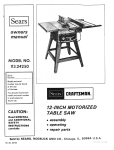
Sears
owners
manual
MODEL
NO.
113.24140
CRRFTSMRN
9-INCH
CAUTION:
Read
and
TABLE
GENERAL
MO TORIZED
SAW
ADDITIONAL
SAFETY
assembly
INSTRUCTIONS
operating
carefully
repair
SEARS, ROEBUCK AND
CO., Chicago,
IL 60684
parts
U.S.A. and SIMPSONS-SEARS
LIMITED,
Part No. 62446
Toronto
Printed in U.S.A.
I
II
I
II I
I
I
II
III
I
I I i
III
general
safety instructions
for power
tools
1. KNOW YOUR POWER TOOL
Read the owner's
manual carefully.
Learn its
application and limitations as well as the specific
potential hazards peculiar to this tool.
12. USE SAFETY GOGGLES
Safety gogglesmust comply with ANS Z87.1-1968.
Also use face or dust mask if cutting operation
dusty.
2. GROUND
ALL TOOLS
This tool is equipped with an approved 3-conductor
cord and a 3-prong grounding type plug to fit the
proper grounding type receptacle. The green conductor
in the cord is the grounding wire. Never connect the
green wire to a live terminal.
WORK
13. SECURE
Use clamps or a vise to hold work when practical. It's
safer than usingyour hand, frees both hands to operate
tool.
3. KEEP GUARDS
IN PLACE
and in working order.
4. REMOVE
ADJUSTING
AND WRENCHES
14. DON'T OVERREACH
Keep proper footing and balance at all times.
15. MAINTAIN
TOOLS WITH CARE
Keep tools sharp and clean for best and safest
performance. Follow instructions for lubricating and
changing accessories.
KEYS
Form habit of checking to see that keys and adjusting
wrenches are removed from tool before turning it on.
5. KEEP WORK AREA CLEAN
Cluttered areas and benches invite accidents.
must not be slippery due to wax or sawdust.
Floor
6. AVOID
DANGEROUS
ENVI RONMENT
Don't use power tools in damp or wet locations. Keep
work area well lit. Provide adequate surrounding work
space.
7. KEEP CHI LDREN
AWAY
All visitors should be kept a safe distance from work
area,
16. DISCONNECT
TOOLS
before servicing; when changing
blades, bits, cutters, etc.
18. USE RECOMMENDED
ACCESSORIES
Consult
the owner's manual for recommended
accessories. Follow the instructions that accompany
the accessories. The use of improper accessories may
cause hazards.
19. NEVER
FORCE
STAND
ON TOOL
Serious injury could occur if the tool is tipped or if the
cutting tool is accidentally contacted,
Do not store materials above or near the tool such that
it is necessary to stand on the tool to reach them.
TOOL
It will do the job better and safer at the rate for which
it was designed.
10. USE RIGHT
TOOL
Don't force tool or attachment to do a job it was not
designed for.
11. WEAR PROPER
APPAREL
No loose clothing, gloves, neckties or jewelry to get
caught in moving parts. Rubber-soled footwear is
recommended for best footing.
20. CHECK DAMAGED
PARTS
Before further use of the tool, a guard or other part that
is damaged should be carefully checked to ensure that it
will operate properly and perform its intended function
- check for alignment of moving parts, binding of
moving parts, breakage of parts, mounting, and any
other conditions that may affect its operation. A guard
or other part that is damaged should be properly
repaired or replaced.
2. That
THIS SAFETY SEAL OF THE
POWER TOOL INSTITUTE ASSURES YOU...
1. That
the
associated
Standards
National
accessories such as
17. AVOI D ACCI DENTAL
STARTING
Make sure switch is in "OFF" position before plugging
in.
8. MAKE WORKSHOP
KID-PROOF
- with padlocks, master switches, or by removing
starter keys.
9. DON'T
is
manufacturer's
with
For
the
Seal,
Safety
Standards
power
are
of
(ANSI).
tools,
produced
Underwriters'
including
in
the
accordance
Laboratories
particular
with
and
tool
with
inspection
3.
That
every
motorized
4.
That
every
tool
rules
for
appl;cable
American
compliance
dependent
tories (UL).
S.
That
the
the tool
is a sponsor
has
applicable
and
tool
with
protection
is inspected
of
Copyright
Institute's
the
standards
conducted
it adequate
manufacturer
of the
safety
testing
by
under
is assured
by
Underwriters'
_n-
Labora-
power.
instructions
and
a
list of
safety
user.
is a member
Consumer
1969 by Power Tool
of the Power
Safely
Inslilute,
Tool
Education
Institute
and
Program.
Inc. All fights
reserved.
additional
safety instructions
WARNING:
FOR YOUR OWN SAFETY,
DO NOT
ATTEMPT
TO OPERATE
YOUR SAW UNTIL
IT IS
COMPLETELY
ASSEMBLED
AND
INSTALLED
ACCORDING TO THE INSTRUCTIONS
. . . AND UNTIL
YOU
HAVE
READ
AND
UNDERSTOOD
THE
FOLLOWING.
1. GENERAL
TOOLS ...
2. GETTING
SAFETY INSTRUCTIONS
SEE PG. 2
FOR
BASIC SAW OPERATION
4.
ADJUSTMENTS
...
SEE PG. 17
5.
MAINTENANCE
...
SEE PG. 20
6.
STABILITY
...
POWER
SEE PG. 11
If there is any tendency
g.
NEVER
place your fingers or hands in the path of
the sawblade or other cutting tool.
NEVER
reach in back of the cutting tool with either
hand to hold
down
or support the workpiece,
remove wood scraps, or for any other reason. Avoid
awkward
operations
and hand positions
where a
sudden slip could cause fingers or hand to move into
a sawblade or other cutting tool.
for the saw to tip over or move
If you attach any kind of table extensions over 24"
wide, make sure they are supported underneath
by a
sturdy brace attached to saw base or bench.
7.
LOCATION
8.
The saw should be positioned
nor a casual observer is forced
saw blade.
KICKBACKS
i.
j.
k.
so neither the operator
to stand in line with the
Kickbacks can cause serious injury: A kickback occurs
when a part of the workpiece
binds between
the
sawblade and the rip fence or other fixed object, rises
from the table, and is thrown toward the operator.
Keep your face and body to one side of the sawblade,
out of line with a possible "Kickback".
Kickbacks
- and possible injury from them -- can
usually be avoided by:
a. Maintaining
the rip fence parallel to the sawblade.
b. Keeping
the sawblade sharp, Keeping points of
anti-kickback
pawls sharp.
c. Keeping
sawblade
guard,
spreader,
and
anti-kickback
pawls in place and operating properly.
The
spreader
must be in alignment
with
the
sawblade and the pawls must stop a kickback
once
it has started. Check their action before ripping.
d. NOT ripping work that is twisted or warped or does
not have a straight edge to guide along the fence.
e. NOT releasing work until you have pushed it all the
way past the sawblade.
f.
Using a push stick for ripping
widths of 2 to 6
inches,
and an auxiliary
fence/push
block
for
ripping
widths narrower
than 2 inches (See section
on "'R ipping").
PROTECTION:
EYES, HANDS,
FACE, EARS, BODY
a. If any part of your saw is malfunctioning,
has been
damaged or broken
... such as the motor switch, or
other operating control,
a safety device or the power
cord
...
cease operating
immediately
until
the
particular
part is properly
repaired or replaced.
b. Wear
safety
goggles
that
comply
with
ANS
Z87.1-1968,
and a face shield if operation
is dusty.
Wear ear plugs or muffs during extended
periods of
operation.
Small loose pieces of wood or other objects that
contact
the rear of the revolving
blade can be
thrown
back at the operator at excessive speed. This
can usually
be avoided
by keeping the guard and
spreader
in place for
all thru-sawing
operations
(sawing entirely
thru the work)
AND by removing
all loose pieces from
the table with a long stick of
wood IMMEDIATELY
after they are cut off.
Use extra
caution
when
the guard
assembly
is
removed
for
resawing,
dadoing,
rabbeting,
or
molding
-- replace
the guard
as soon
as that
operation
is completed.
NEVER
turn the saw "ON"
before clearing the table
of all tools, wood scraps, etc., except the workpiece
and related feed or support devices for the operation
planned.
NEVER
place
cutting tool.
h.
as cutting
boards, the
saws
f.
OF SAW
during
certain
cutting
operations
such
extremely
large heavy panels or long heavy
saw should be bolted down,
c.
e.
TO KNOW YOUR SAW . . . SEE PG. 8
3.
9.
d.
for table
your
face
or body
in
line
with
the
DO NOT perform
anY operation
"FREEHAND"
always
use either the fence or the miter gauge to
position
and guide the work.
NEVER
use the fence when
crosscutting
or the
miter gauge when ripping.
DO NOT use the fence as
a length stop.
Shut "OFF"
the saw and disconnect
the power cord
when removing the table insert, changing the cutting
tool,
removing
or replacing
the blade guard, or
making adjustments.
I.
Provide
adequate
support
to the rear and sides of
the saw table for wider or long workpieces.
m.
Plastic and composition
(like hardboard)
materials
may be cut on your saw. However,
since these are
usually
quite hard and slippery,
the anti-kickback
pawls may not stop a kickback.
Therefore,
be especially
attentive
to following
proper
set-up and cutting procedures
for ripping
these materials.
Do not stand, or permit anyone else
to stand, in line with a potential
kickback.
10. KNOW
a.
YOUR
CUTTING
TOOLS
Dull,
gummy,
or improperly
sharpened
or set
cutting
tools can cause material
to stick, jam, stall
the saw, or kickback
at the operator.
Minimize
potential
injury by proper cutting tool and
machine maintenance.
NEVER
ATTEMPT
TO
FREE
A
STALLED
SAWBLADE
WITHOUT
FIRST
TURNING
THE
SAW OFF.
b.
Never use grinding
wheels, abrasive cut-off
wheels,
friction
wheels (metal slitting blades), wire wheels or
buffing wheels.
11. NOTE
THE FOLLOWING
APPEARS ON THE FRONT
DANGER
OF THE
LABEL
SAW.
WHICH
DANGER
FOR
1_
2.
3.
=K
5.
YOUR
OWN
SAFETY
READ
AND
UNDERSTAND
OWNER'S
BEFORE
OPERATING
MACHINE.
WEAR
SAFETY
GOGGLES.
KEEP
HANDS
OUT
OF PATH
OF SAW
KNOW
HOW
TO AVOID
"KICKBACKS".
USE
I'PUSH-ST|CK
"_ WHEN
RIPPING
NARROW
WORK.
MANUAL
BLADE_.
SHORT
OR
12. THINK SAFETY
Safety is a combination of operator common sense and
alertness at all times when the saw is being used.
WARNING:
DO
NOT
ALLOW
FAMILIARITY
(GAINED FROM FREQUENT USE OF YOUR SAW)
TO
BECOME
COMMONPLACE.
ALWAYS
REMEMBER THAT A CARELESS FRACTION OF A
SECOND IS SUFFICIENT
TO INFLICT
SEVERE
INJURY.
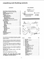
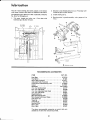
unpacking
and checking contents
CONTENTS
TOOLS NEEDED
General Safety Instructions for Power Tools .........
Additional Safety Instructions for Bench Saws .......
Guarantee
...................................
Unpacking and Checking Contents
................
Table of Loose Parts ...........................
Assembly ....................................
Installing Blade Guard ........................
Getting To Know Your Saw
.....................
Operating Controls
..........................
Removing Table Insert .......................
Removing and Installing Saw Blade ..............
On-Off Switch ..............................
Motor Specifications and Electrical Requirements ....
Basic Saw Operation
..........................
Crosscutting ..............................
Miter Cutting
.............................
Bevel Cutting
.............................
Compound Miter Cutting
....................
Ripping ..................................
Resawing .................................
Rabbeting ................................
Adjustments
Miter Gage ...............................
Heeling Adjustment
........................
Rip Fence ................................
Table Insert ...............................
Blade Tilt
................................
Maintenance
................................
Lubrication
.................................
Recommended Accessories .....................
Trouble Shooting .............................
Repair Parts .................................
Me
imSlew
iver
2
3
2
4
4
5
6
8
8
8
9
9
10
11
11
12
12
12
13
16
17
1/2" Wrench
7/16"" Wrench
Combination Square
17
17
18
18
19
20
21
21
22
24
4
5
Your Craftsman 9 inch Motorized Table Saw is shipped
complete in one carton. Floor base and table extensions are
optional accessories.
Key No.
1
2
3
4
5
6
7
8
9
Separate all parts from packing materials and check each
one with the illustration and the "Table of Loose Parts" to
make certain all items are accounted for, before discarding
any packing material.
If any parts are missing, do not attempt to assemble the
table saw, plug in the power cord or turn the switch on
until the missing parts are obtained and are installed
correctly.
Remove the protective
oil that is applied
and edges of the table. Use any ordinary
grease and spot remover.
to the table top
household
type
CAUTION:
Never use gasoline, naptha or similar highly
volatile solvents.
Apply
a coat of automobile
Wipe all parts thoroughly
wax
with
to the table.
a clean, dry cloth.
WARNING:
FOR
YOUR
OWN SAFETY,
NEVER
CONNECT PLUG TO POWER SOURCE OUTLET UNTIL
ALL ASSEMBLY STEPS ARE COMPLETE.
4
Part Name
Miter Gauge..............................
BladeGuardandSpreader ...................
Rip Fence................................
Wrench,Arb0r .............................
Wrench,Shaft.............................
Crank Asm...............................
OwnersManual............................
Bar,FenceGuide...........................
Bagof LoosePartsPart No. 62455 .............
Clamp-Spreader..........................
Bolt, Carriage1/4-20 x 1-3/4 ................
L0ckwasher,Int. 1/4 ......................
Nut, Hax 1/4-20 x 7/16 x 3/16 ..............
Washer,17/64 x 7/16 x 1/32 ................
WingScrew .............................
SetScrewWrench,1/8 ....................
SetScrewWrench,3/16 ...................
Switch Keys ............................
Bracket ................................
Screw,Pan Hal.10-32x 3/4 .................
Lockwasher,Int. No. 10 ...................
Nat. Hex 10-32 ..........................
Qty.
1
1
1
1
1
2
1
1
1
2
2
2
2
2
2
i
1
2
1
3
3
3
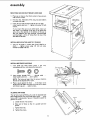
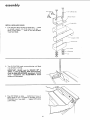
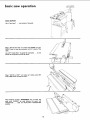
assembly
MOUNTING
1.
SAW ON CRAFTSMAN
Place saw on base so that
with corners of base.
front
FLOOR BASE
corners of saw are even
2.
Find four hex. head bolts
furnished
with base.
3.
Insert all four bolts through holes in saw and base ...
install washers and nuts ... tighten nuts using 1/2 inch
wrench.
3/4
in. long, nuts and washers
If you mount
the saw on any other bench, make sure
that there is an opening in the top of the bench the
same size as the opening
in the bottom of the saw so
that the sawdust can drop through.
Recommended
working
height
is 33 to 37 inches from the top of the
saw table to the floor.
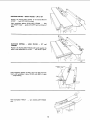
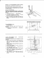
INSTALLING
1.
2.
AND TILT CRANKS
Line up set screw in cranks with FLAT SPOTS on
shafts ...
tighten screws using 1/8 inch set screw
wrench furnished with saw.
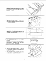
INSTALLING
1.
ELEVATION
FENCE GUIDE BAR
Find
three pan head screws 10-32 x 3/4
Iockwashers and hex. nuts among the loose parts.
Insert screws through BAR ...
through
install washers and nuts ... don't tighten.
table
inch,
FENCE
GUIDE
BAR
...
NOTE: The holes are larger than the screws, therefore
the bar can be adjusted UP or down.
3/4
IN.
SCREWS
3. Place a square against the fence ... if the fence is not
square with the table, move one end of bar UP or down
until fence is square ... tighten screws.
ALIGNING
RIP FENCE
The rip fence must be PARALLEL with the Sawblade and
Miter Gage grooves. Push fence head against table ... move
fence until it is along side of groove. It should be parallel to
groove. If it is not;
a.
Loosen the two "hex screws".
b.
Move end of fence so that it is parallel
groove.
c.
Tighten the knob.
d. Tighten the screws.
LOOSEN
RIP
FENCE
HEAD
with the
assembly
WiNG
SCREW
CARRIAGE
CLAMP
INSTALLING
BLADE GUARD
Find the parts shown among the loose parts ... attach
to spreader support rod at the back of the saw ...
screw in wing screws ... screw on nuts but DO NOT
TIGHTEN THEM.
2.
Turn ELEVATION
crank counterclockwise
is up as high as it will go.
until
blade
IMPORTANT:
BLADE must be SQUARE 90 ° to
TABLE, in order to INSTALL Blade Guard Correctly.
Check for Blade SQUARENESS, according to "BLADE
TILT"
adjustments. See ADJUSTMENTS
section
further on in this manual.
Place RIP
FENCE
on table
...
against blade so that it is parallel
TOUCHES
tips of saw teeth
...
LOCK KNOB.
CAREFULLY
move it
to the blade, and just
tighten
RIP FENCE
6
BOLT
BLOCK
i
IMPORTANT:
Make a black pencil line on the guide
bar at the end of the rip fence head. This will be
explained
further
on in this manual
under "Basic
Operation"
. .. ripping ...
\
4.
Place BLADE GUARD on table .., engage slots in
SPREADER with WING SCREWS ... move spreader
toward front of saw so that wing screw is at end of slot
•.. TIGHTEN wing screws.
NUIS
BOLTS
AND
LOOSE
_
SPACE EQUAL TO
3 THICKNESSES OF PAPER
IMPORTANT
- The SPREADER
must always be
PARALLEL to the sawblade and in the MIDDLE of the
cut (KERF) made by the sawblade.
/
, _
]
LOOKING
Fold LOOSE
thicknesses,
PARTS
LIST
twice making
the pawls
7.
ON
LOOSEPARTS LIST
/
FOLDED
Lift up both ANTI-KICKBACK
of the SETSCREW
WRENCHES
DOWN
THREE
The spreader i$ thinner
than the width of the KERF by
approximately
six thicknesses
of paper. The folded
parts list will be used as a "spacing g au ge. "
6.
WOOD
/
SPREADER
5.
KERF
PAWLS
...insertone
in the notches to hold
out of the way.
Insert folded
paper between
SPREADER
and FENCE
•.. hold spreader flat against fence
... tighten NUTS
on clamp screws ... using 7/16 inch wrench.
SETSCREW
WRENCH
7
PARTS
LIST
SAW
BLiDE
_
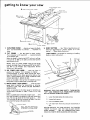
getting to know your saw
ANTI-KICKBACK
4
MITER
GAUGE
LOCK
PAWLS
HANDLE
HOLES
ATTACHING
3
FOR
FACING
RIP FENCE
LOCK
I
ELEVATION
CRANK
5
RESET
TILT
BUTTON
ON-OFF
ELEVATION CRANK ... elevatesor lowersthe blade.
Turn counterclockwise
Iowe r.
to
elevate
...
clockwise to
2. TILT CRANK
... tilts the blade for bevel cutting.
Turn clockwise to tilt toward left ... counterclockwise
to tilt toward right.
When the blade is tilted to the LEFT as far as it will go,
it should be at 45 ° to the table and the bevel pointer
should point to 45 ° .
RESET BUTTON ....
See "Motor Specifications and
Electrical Requirements"
section further on in this
manual ..."Motor
Safety Protection."
TABLE INSERT is removable for removing or installing
blades or other cutting tools ...
NOTE: There are LIMIT STOPS inside the saw which
prevent the blade from tilting beyond 45 ° to the LEFT
and 90 ° to the RIGHT. (See Adjustments
Section
further on in this manual).
3.
RIP FENCE LOCK KNOB ...
locks the fence in
position for ripping. Turn clockwise to tighten ...
counterclockwise to loosen, While moving the fence,
keep the HEAD of the fence against the table so that
fence is always PARALLEL
to blade. ALWAYS LOCK
FENCE SECURELY, WHEN IN USE.
Holes are provided in the rip fence for attaching a wood
facing when using the dado head or molding head.
4.
MITER fiAIJGE LOCK HANDLE
... locks the miter
gauge head in position for crosscutting or mitering.
ALWAYS
LOCK THE MITER GAUGE SECURELY
WHEN IN USE.
Holes are provided in the miter gauge for attaching an
AUXILIARY
FACING to make it easier to cut long
pieces.
Select a suitable piece of smooth straight wood ... drill
two holes through it and attach it with small screws and
nuts. The nuts go inside of the miter gaugeor ... drill
1/4 inch holes all the way through the head. Then you
can attach the facing with wood screws.
AUXILIARY
PACING
CRANK
SWITCH
LIFT
LIP
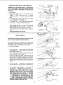
WARNING:
FOR YOUR OWN SAFETY, TURN SWITCH
"OFF"
AND REMOVE PLUG FROM POWER SOURCE
OUTLET BEFORE REMOVING INSERT.
1.
Lower the blade below the table surface.
2.
Loosen both screws.
3.
Lift anti-kickback
4,
Lift
insert from
pawls,
front end, and pull toward front of
SaW.
NOTE:
WHEN BEVEL CROSSCUTTING,
ATTACH FACING
SO THAT IT EXTENDS
TO THE RIGHT OF THE MITER GAUGE,
NEVER OPERATE THE SAW WITHOUT THE PROPER
INSERT IN PLACE. USE THE SAW BLADE INSERT
WHEN SAWING ... USE THE COMBINATION
DADO
MOLDING INSERT WHEN DADOING OR MOLDING.
REMOVING
AND INSTALLING
PULL
SAWBLADE
TO
LOOSEN
WARNING:
FOR YOUR
OWN SAFETY,
TURN
SWITCH
"OFF"
AND
REMOVE
PLUG
FROM POWER
SOURCE
OUTLET
BEFORE
REMOVING
OR
INSTALLING
SAWBLADE.
1.
Remove
2.
Place
insert.
OPEN
ARBOR
wrenches
blade.
OPEN END
WRENCH
END
wrench
...
BOX
as shown
3.
With
OPEN
END
wrench FOREWARD
4.
To TIGHTEN
rear of table
wrench
...
hold
on
flat
surfaces
saw
on nut
...
position
your hands well above
wrench
against table,
to LOOSEN
nut.
nut ...
... PUSH
of
PULL
BOX
HOLD
open end wrench against
box wrench toward rear.
FLAT
SURFACES
When installing
the blade
... make sure the teeth are
pointing
toward
the front of the saw ... and that the
blade and collars are clean, and free from any burrs.
The HOLLOW
blade.
side of
the collars
must
be against
the
COLLAR
HEX
NUT
l
TEETH
POINTIN(
FRONT
OF
SAW
Always tighten the arbor nut securely.
ON-OFF SWITCH
CAUTION: Before turning switch on, make sure the blade
guard is correctly installed and operating properly.
The On-Off
PREVENT
HAZARDOUS
Switch
has a locking
UNAUTHORIZED
USE BY CHILDREN
feature. THIS SHOULD
AND
POSSIBLY
AND OTHERS.
KEY
©
KEY
1.
2.
Insert
key
into switch.
_ON-OFF
TO turn saw ON ... stand to either side of the blade
never in line with it ... insert finger under switch lever
and pull END of switch out.
After
turning
switch ON, always
allow
come up to full speed before cutting.
the
blade
to
Do not cycle the motor switch
on and off rapidly,
as
this may cause the sawblade to loosen. In the event this
should ever occur,
allow
the sawblade to come to a
complete stop and retighten
the arbor nut normally,
not excessively.
Never leave the saw while the power is
"ON".
3.
TO turn saw OFF ... PUSH lever in. Never leave the
saw until the cutting tool has come to a complete stop.
TO lock switch in OFF position ... hold switch IN
with one hand ... REMOVE key with other hand.
WARNING:
FOR YOUR OWN SAFETY,
LOWER
BLADE OR OTHER CUTTING TOOL BELOW TABLE
SURFACE,
AND ALWAYS
LOCK THE SWITCH
"OFF". WHEN SAW IS NOT IN USE ... REMOVE
KEY AND KEEP IT IN A SAFE PLACE ... ALSO
... IN THE EVENT OF A POWER FAILURE (ALL
OF YOUR LIGHTS GO OUT) TURN SWITCH OFF
• .. LOCK IT AND REMOVE THE KEY. THIS WILL
PREVENT THE SAW FROM STARTING UP AGAIN
WHEN THE POWER COMES BACK ON.
SWITCH
(YELLOW PLAS_IC)
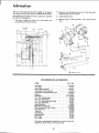
motor specifications
and electrical
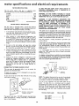
MOTOR SPECl FICATIONS
The
AC motor
used in this saw
non-reversible type, with the following
is a capacitor
specifications:
start,
IF YOU ARE NOT SURE THAT YOUR OUTLET IS
PROPERLY GROUNDED,
HAVE IT CHECKED BY A
QUALIFIED ELECTRICIAN.
120
10.0
60
WARNING:
DO NOT PERMIT FINGERS TO TOUCH
THE TERMINALS
OF PLUGS WHEN INSTALLING
OR
REMOVING THE PLUG TO OR FROM THE OUTLET.
Voltage
................................
Amperes
..............................
Hertz
...................................
Phase
................................
RPM
.................................
Rotation
(viewed from
sawblade end)
...............
MOTOR SAFETY
The saw motor
is equipped
overload
protector,
designed
when the motor temperature
1.
If the protector
move the
immediately
Single
3450
WARNING:
IF NOT PROPERLY
GROUNDED
THIS
POWER TOOL CAN INCUR THE POTENTIAL HAZARD
OF ELECTRICAL
SHOCK, PARTICULARLY
WHEN
USED IN DAMP LOCATIONS,
IN PROXIMITY
TO
PLUMBING, OR OUT OF DOORS. IF AN ELECTRICAL
SHOCK OCCURS THERE IS THE POTENTIAL
OF A
SECONDARY
HAZARD
SUCH AS YOUR
HANDS
CONTACTING THE SAWBLADE.
Counterclockwise
PROTECTION
with
a manual-reset
thermal
to open the power line circuit
exceeds a safe'value.
This power tool is equipped with a 3-conductor cord and
grounding type plug which has a grounding prong, approved
by Underwriters' Laboratories and the Canadian Standards
Association. The ground conductor has a green lug and is
attached to the tool housing at one end and to the ground
prong in the attachment plug at the other end.
opens the line and stops the saw motor,
saw switch
and allow
lever to
the motor
the "OFF"
to cool.
position
After
cooling
to a safe operating
temperature,
the
overload
protector
can be closed manually
be pushing
in the red RESET button on the front of saw. If the red
button
will not snap into place immediately,
the motor
is still too hot and must be allowed to cool for a while
longer.
3.
4.
This plug requires a mating 3-conductor grounded type
outlet as shown.
If the outlet you are planning to use for this power tool'is "
of the two prong type
DO NOT REMOVE
OR ALTER
THE GROUNDING
PRONG
IN ANY
MANNER.
Use an
As soon as the red button
will snap into
running
position,
the saw may be started and operated normally
by moving the saw switch lever to the "ON"
position.
adapter as shown
known ground.
Frequent
opening of fuses or circuit
breakers may result
if motor
is overloaded,
or if the motor circuit
is fused
with a fuse other than those recommended.
Do not use
a fuse of greater
company.
capacity
without
consulting
ADAPTER
\
3-PRONG\
/
I
LUG
MAKeSURE
Tn_S_S
I%- I...-L---CO.NECTED
TOA
PLuG "
J K.ow. oRou.0
--
If your unit is for use on less than 150 volts it has a plug
that looks like below.
NOTE:
PLUG
The adapter
_
illustrated
RECEPTACLE
is for use only
if you already
have a properly
grounded
2-prong
receptacle.
not allowed in Canada by the Canadian Electrical
Adapter
Code.
is
The use of any extension
cord will cause some loss of
power.
To
keep this
to a minimum
and to prevent
over-heating
and motor
burn-out,
use the table below to
determine
the minimum
wire size (A.W.G.)
extension cord.
GROUNDING
Use only
3 wire extension
cords
which
have 3 prong
grounding
type plugs and 3-pole receptacles
which accept
the tools plug.
PRONG
PROPERLY GROUNDED
3-PRONG
lug to
you have a qualified
electrician
outlet
with a properly grounded
GROUNDING
If power cord is worn or cut, or damaged in any way, have
it replaced immediately.
_
the grounding
An adapter as shown below is available for connecting plugs
to 2-prong receptacles. The green grounding lug extending
from the adapter must be connected to a permanent ground
such as to a properly grounded outlet box.
This saw must be grounded while in use to protect the
operator from electrical shock.
<
connect
the power
TO POWER SOURCE OUTLET
3-PRONG
and always
It is recommended
that
replace the TWO prong
THREE
prong outlet.
Although
the motor is designed
for operation
on the
voltage
and frequency
specified on motor
nameplate,
normal
loads will be handled
safely on voltages
not
more than 10% above or below the nameplate
voltage.
Heavy loads, however,
require
that voltage at motor
terminals
be not less than the voltage specified
on
nameplate.
CONNECTING
requirements
Extension Cord Length
OUTLET
Upto
100 Ft ...............
100-200
Ft ...............
200-400
Ft ...............
Plug power cord into a 110-120V properly grounded type
outlet protected by a 15-amp. time delay or Circuit-Saver
fuse or circuit breaker.
i0
Wire Size A.W.G.
12
10
8
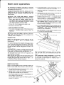
basic saw operation
We recommend
the following
instructions
for operating
your saw so that you get the best results and to minimize
the likelihood
of personal injury.
CROSSCUTTING,
MITER
CUTTING,
COMPOUND
MITER
CUTTING
and
the end of a narrow
MITER GAGE.
workpiece
are performed
using
the
Never
make
these cuts freehand
(without
using the
miter gage or other auxiliary
devices) because the blade
could bind in the cut and cause a KICKBACK
or cause
your fingers or hand to slip into the blade.
2.
Always
lock
the miter
3.
Remove
4.
Make sure blade guard is installed.
5.
Have blade extend approximately
workpiece.
Additional
blade
hazardous.
rip fence from
Do not stand directly in front of the blade in case of a
KICKBACK. Stand to either side of the blade.
7.
Keep your hands clear of the blade and out of the path
of the blade.
8.
If blade stalls or stops while cutting, TURN SWITCH
OFF before attempting to free the blade.
9.
Do not reach over or behind the blade to pull the
workpiece through the cut ...
to support long or
heavy workpieces ... to remove small cut-off pieces of
material or FOR ANY OTHER REASON.
BEVEL CUTTING,
RABBETING
across
WARNING:
FOR YOUR OWN SAFETY,
ALWAYS
OBSERVE THE FOLLOWING SAFETY PRECAUTIONS.
1.
6.
gage securely
when
10. Do not pick up small pieces of cut-off material from the
table. REMOVE them by pushing them OFF the table
with a long stick. Otherwise they could be thrown back
at you by the rear of the blade.
in use.
11. Do not remove
small pieces of cut-off material that may
become TRAPPED
inside the blade guard while the saw
is RUNNING•
THIS
COULD
ENDANGER
YOUR
HANDS
or cause a KICKBACK.
table.
1/8 inch above top of
exposure
could
be
Turn the saw OFF. After
lift the guard and remove
• NOTE: Glue a piece of sandpaper to the face of the miter
gauge head. This will help prevent the workpiece from
"creeping" while it is being cut.
the blade has stopped
the piece.
HOLD
DOWN
turning,
CLAMP
CROSSCUTTING
NOTE: The space between the miter gauge bar and the
groove in the table is held to a minimum during
manufacturing.
For maximum accuracy when using the miter gauge, always
"favor" one side of the groove in the table. In other words,
don't move the miter gaugefrom side to side while cutting,
but keep one side of the bar riding against one side of the
groove.
CROSSCUTTING
is known
as cutting
wood
across the
grain, at 90 °, or square with both the edge and the flat side
of the wood. This is done with the miter gage set at "'0".
The miter gage may be used in either
table. Make sure it is locked.
When using the
with
your
right
hand.
of the grooves in the
When using the miter gage in the LEFT hand groove, hold
the workpiece firmly against the miter gage head with your
left hand, and grip the lock handle with your right ... or
use Hold-Down Clamp (Optional Accessory).
RIGHT
hand groove, hold
hand and the Iockhandle
the workpiece
with your left
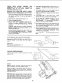
THE ADJUSTABLE TABLE EXTENSION is recommended
for supporting long workpieces while crosscutting ... or
you can make a simple support by clamping a piece of
plywood to a sawhorse.
STOP RODS
REPETITIVE
CUTTING
REPETITIVE
CUTTING is known as cutting a quantity of
pieces the same length without having to mark each piece.
PLYWOOD CLAMPED
TO SAWHORSE
Use the Stop Rods (optional
accessory) only for cutting
duplicate
pieces 6 inches long and longer.
2.
NEVER
guide or support
the workpiece
extending
the edge of the saw table with your free hand.
When making repetitive
sure to support
it from
You can make a simple
plywood
to a sawhorse.
cuts from
the floor.
support
a long workpiece,
by clamping
over
be
a piece of
11
lubrication
The saw motor
bearings have been packed at the factory
with proper lubricant
and require no additional lubrication.
2.
The following
parts should be oiled
No. 20 or No. 30 engine oil.
occasionallv
3.
Cradle
4.
1.
nut.
Bearing
fence.
Tilt
screw threads and pivot
Craftsman
gum & pitch remover.
(First
with
SAE
clean
with
Elevation
Craftsman
screw threads and pivot
gum & pitch remover.
bearing
points
nut.
NUT
_
TILT
in guard
assembly,
miter
SCREW
MOTOR
[LEVATION
': _
i-"
-
CRADLE
GUARD
sc.ew
-- -_
_lVOT
NUT ...... _
I
t_1 rillIP
J]];'J_II[
i_
I_
II!lilIIII
J ],.........t
IlL J J.LL
o _-
MITER
GAUGE
_JlII1!III IP-_/_
l
FENCE
"_
RECOMMENDED
BEARING
ACCESSORIES
ITEM
CAT. NO.
Steel Base .............................
Tool Bench
.............................
Solid Table Extension
....................
Adjustable Table Extension
.................
Combination Dado/Molding Insert
..........
Casters ................................
Sawblades
...........................
7-In. Dia. Molding Head ....................
6-In. Dia. Dado Head ......................
7-In. Dia. Adjustable Dado Head .............
7-In. Dia. Dedo Head ......................
Blade Stabilizers
.........................
Miter-Gauge Stop Rods ....................
Miter-Gauge Hold-Down Clamp ..............
Hold-Down Set
..........................
Taper Jig ...............................
Universal Jig
............................
Sanding Wheel ...........................
Work Light
.............................
Work Light
.............................
9-22214
9-1071
9-24277
9-2178
9-29934
9-22201
See Catalog
9-3217
9-3249
9-3267
9-3257
9-4952
9-29924
9-29928
9-3230
9-3233
9-3231
9-2274
9-2480
9-2481
The above recommended
accessories are current
available at the time this manual was printed.
21
Clean with
points.
TILT SCREW
PIVOT
(First
and were
POINTS
gauge and rip
RIPPING, BEVEL RIPPING, RESAWINGAND
RABBETING
(alongthe edgeof a workpiece)are
performedusing the RIP FENCE togetherwith
AUXILIARY
devices
whenrequired.
WARNING: FOR YOUROWNSAFETY,ALWAYS
OBSERVE
THEFOLLOWING
SAFETYPRECAUTIONS.
Nevermake these cuts FREEHAND (without using the
rip fence or auxiliary devices when required) because
the blade
could bind in the cut and cause a
KICKBACK.
2.
Always lock the rip fence securely when in use.
3.
Remove miter gage from table.
4.
Make sure blade guard is installed for all rip type cuts.
Replace
the guard
IMMEDIATELY
following
completion of resewing, rabbeting, dadoing, or molding
operations.
Have blade extend approximately
1/8 inch above top of
workpiece.
Additional
blade exposure could be
hazardous.
6.
Do not stand directly in front of the blade in case of a
KICKBACK. Stand to either side of the blade.
7.
Keep your hands clear of the blade and out of the path
of the blade.
8.
If the blade stalls or stops while cutting, TURN
SWITCH OFF before attempting to free the blade.
9.
Do not reach over or behind the blade to pull the
workpiece through the cut ...
to support long or
heavy workpieces .... to remove small cut-off pieces of
material or FOR ANY OTHER REASON.
10. Do not pick up small pieces of cut-off
material from the
table. REMOVE
them by pushing them OFF the table
with a long stick. Otherwise
they could be thrown
back
at you by the rear of the blade.
Frequently check the action of the ANTI-KICKBACK
PAWLS by passing the workpiece alongside of the
spreader while saw is OFF.
11. Do not remove small pieces of cut-off material that may
become TRAPPED inside the blade guard while the saw
is RUNNING.
THIS COULD
ENDANGER
YOUR
HANDS or cause a KICKBACK.
Pull the workpiece TOWARD you. If the PAWLS do
not DIG into the workpiece and HOLD it ... the pawls
must be SHARPENED. Refer to "Maintenance" section
further on in this manual.
Certain ripping cuts require the use of Auxiliary
5.
Turn the saw OFF
piece.
. .. lift the guard and remove the
Devices,
Learn to know WHEN and HOW to use these devices for
NARROW ripping. You can make them from scraps of
wood.
I-5/8
IN
_-S°
PUSH STICK
Make one using a small piece of 1 x 2.
318 ,,
AUXl LIARY
FENCE/PUSH
BLOCK
F--6 -__. !
Make one using a piece of 3/8 inch plywood and a small
piece of 2 x 4.
iI__,tA
I
3/8
_-
RIPPING
RIPPING is known as cutting a piece of wood with the
grain, or lengthwise. This isdone using the rip fence.
Position the fence to the desired WIDTH OF RIP by
measuring the distance from the "pencil mark" (which you
made when Installing the Blade Guard) to the end of the rip
fence head and lock it.
NOTE: When bevel ripping 6 inches or narrower use fence
on the right side of the sawblade ONLY. This will provide
more space between the fence and the sawblade for use of a
push stick. If the fence is mounted to the left, the sawblade
guard may interfere with the proper use of a push stick.
13
4"
NOTCH
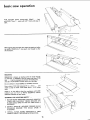
basic saw operation
WORK
ALwAvs,op ,
LONO
SUPPORT
Use a "saw
horse"
...
and a piece of plywood.
//
When "WIDTH
OF RIP" is 6 inches and WIDER
use your
RIGHT
hand to feed the workpiece
until it is clear of the
table.
Use LEFT hand ONLY to guide the workpiece
FEED the workpiece with the left hand.
...
do not
When "WIDTH of RIP" is 2 inches to 6 inches wide USE
THE PUSH STICK to feed the work.
When WIDTH of RIP is NARROWER than 2 inches, the
push stick CANNOT be used because the guard will
INTERFERE
...
USE the AUXILIARY
FENCE/PUSH
BLOCK.
14
WORKP[ECES
NARROW
Position
OF RIP
RIPPING - SHORT PIECES - UP TO 18"
the AUXILIARY
FENCE to
... lock RIP FENCE in place.
Hold workpiece
against AUXILIARY
with RIGHT
hand ... guide with LEFT
table.
NARROW
LONGER
RIPPING
-
LONG
the
desired
WIDTH
FENCE
,..
feed
hand until clear of
PIECES
/
-
18"
and
Position the AUXILIARY
FENCE with handle against the
table to the desired WIDTH of RIP .,. lock fence in place.
WORKPIECE
END
EVEN
OF
WITH
TABLE
Hold workpiece against auxiliary fence and feed with left
hand until workpiece is about EVEN with END of table
•., Stop Feeding.
/
Hold workpiece
over ...
FIRMLY
...
turn AUXILIARY
FENCE
HOLD
15
WORKPISCE
FIRMLY
basic saw operation
Hold workpiece
against AUXILIARY
with RIGHT Hand ... guide with LEFT
table,
FENCE
...
feed
hand until clear of
BAFFLE
When ripping thin strips
the baffle, CAREFULLY
the workpiece.
that may enter the guard and strike
raise guard only enough to clear
RESAWING
RESAWING
is known as ripping a piece of wood through,
its thickness. To RESAW a piece of wood wider than 2-1/8
inch ...
it will be necessary to remove
and use an AUXl LIARY
FENCE which
Do not attempt
to resaw BOWED
the blade guard
you can make,
or WARPED
...
material.
Use a piece of 3/8 inch plywood
9 in. x 20 in ....
attach
a strip of wood
1-5/8 inches thick
x 2-1/2
wide.
WIDER
and
inches
THAN
2-1/8"
\
Clamp it to the table so that the workpiece will SLIDE
EASILY
but not TILT or MOVE SIDEWAYS without
BINDING between the two fences.
9"
\<'"
AUX[L{ARY
WARNING:
FOR YOUR OWN SAFETY
...
1. NEVER RESAW FREEHAND (WITHOUT USING RIP
FENCE AND AUXILIARY
FENCE) BECAUSE THE
BLADE COULD BIND IN THE CUT AND CAUSE A
KICKBACK.
2.
DO NOT "BACK UP" (REVERSE FEEDING) WHILE
RESAWlNG
BECAUSE THIS COULD
CAUSE A
KICKBACK.
3.
INSTALL
BLADE GUARD
IMMEDIATELY
UPON
COMPLETION OF THE RESAWlNG OPERATION.
16
FENCE
m.
RABBETING
Rabbeting
is known
of a piece of material.
as cutting
out a section of the corner
To make a RABBET
requires two cuts which do not go all
the way through the material. Therefore
the blade guard
must be removed.
1.
Remove
2.
Adjust
3.
Make
first
procedure.
4.
Remove
RABBET
blade guard.
rip fence and blade to required
auxiliary
cut
through
edge.
dimensions.
Follow
fence and make second
5.
resawing
INSTALL
BLADE GUARD
IMMEDIATELY
COMPLETION OF RABBETING OPERATION.
UPON
Rabbet cuts can also be made using the dado head or
molding head.
cut.
adjustments
WARNING:
FOR
YOUR OWN SAFETY,
TURN
SWITCH "OFF" AND REMOVE PLUG FROM POWER
SOURCE
OUTLET
BEFORE
MAKING
ANY
ADJUSTMENTS.
MITER
GAUGE
NOTE: The graduations are manufactured
to very close
tolerances which provide suitable accuracy for average
woodworking. In some cases where extreme accuracy is
required, when making angle cuts, for example, make a trial
cut and then recheck it.
If necessary, the miter gauge head can then be swiveled
slightly to compensate and then locked.
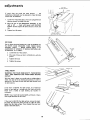
2.
The HEAD should be SQUARE
the pointer points to "0".
3.
(900 ) with the bar when
Position the head square with the bar ...
handle.
tighten the
Loosen the screw and adjust the pointer, so it points to
zero.
To check for squareness, place an accurate square on the
miter gauge. If the head is NOT SQUARE with the bar:
1.
The swiveling movement of the bead can be adjusted by
tightening or loosening the set screw located in side of the
head using the 1/8 inch setscrew wrench.
Loosen the lock handle.
HEELING
ADJUSTMENT
or PARALLELISM
SAWBLADE TO MITER GAUGE GROOVE.
OF
While cutting,
the material
must
PARALLEL
to the SAWBLADE
line
the
miter
gauge GROOVE
and
PARALLEL
to the SAWBLADE.
the
move in a straight
. . . therefore
both
RIP
FENCE
must
be
MARK
If the sawblade IS NOT parallel to the miter gauge groove,
the blade will bind at one end of the cut.
To check for parallelism:
WARNING - FOR YOUR OWN SAFETY, TURN SWITCH
"OFF AND REMOVE PLUG FROM POWER SOURCE
OUTLET.
1.
Raise blade all the way up
. ., raise blade guard.
2.
Mark an "X"
to the LEFT.
3.
Place the head of a combination square in the
GROOVE
... adjust blade of square so that it just
touches the tip of the MARKED tooth.
4.
Move square to REAR, rotate blade to see if MARKED
tooth again touches blade of square.
5.
If tooth touches square the same amount at FRONT
and REAR ... miter gage groove IS PARALLEL to
BLADE.
on one of the teeth
which
is SET
(bent)
17
"X"
ON
TOOTH
L
adjustments
3/16
SET
SCREW
iNCH
WRENCH
SCREWS
If
tooth
does
mechanism
PARALLEL
not
touch
the
underneath
must
to GROOVE.
same
be adjusted
amount
..
the
to make the blade
1.
Loosen four (4) screws (about 1/2 turn) using 3/16 inch
setscrewwrench furnished with saw,
2.
Move
the
end
of the
SPREADER
SUPPORT
to
the
right or left
...
check with square until
MARKED
TOOTH
touches square the same amount
at front
and
rear.
3.
Tighten four (4) screws,
SPREADER SUPPORT
(MOVE RIGHI OR LEFT)
RIP FENCE
The rip fence should be PARALLEL with the sawblade and
the MITER
GAGE GROOVES.
PUSH FENCE HEAD
AGAINST
TABLE
...
MOVE FENCE UNTIL IT IS
ALONGSIDE OF GROOVE. IT SHOULD BE PARALLEL
TO GROOVE. IF IT IS NOT,
a.
Loosen the two "hex screws".
b.
Move end of fence so that it is PARALLEL
groove.
c.
Tighten the knob.
RiP
FENCE
HEAD
with the
d. Tighten the screws.
LEVELING
TABLE INSERT
WARNING:
FOR YOUR OWN SAFETY, TURN SWITCH
"OFF"
AND REMOVE PLUG FROM POWER SOURCE
OUTLET.
STRAIGHT
With the insert in place, use a small scale or straight edge to
check near each of the six leveling tab positions, in order to
determine if the insert is even with saw table surface at all
six tab locations.
If the insert is ABOVE the table surface, lay a hardwood
block on saw table so it extends over the insert and strike
block with a mallet at each leveling tab location in
succession.
NOTE: Tap at each tab location lightly until level. A heavy
blow might bend the tab too much.
If the insert is BELOW the table surface, remove the insert
and bend the tabs (with pliers) enough to make the insert
higher than the table surface. Then re-install the insert and
adjust as described above.
18
EDGE
TAB
1
BLADE TILT, OR SQUARENESS OF BLADE TO TABLE
90 ° (SQUARE) and 45 ° (BEVEL) STOP COLLARS.
When the bevel pointer is pointing directly to the "0" mark
on the bevel scale, the sawblade should make a SQUARE
cut 90 ° to the table.
To check for SQUARENESS:
WARNING; FOR YOUR OWN SAFETY, TURN SWITCH
"OFF"
AND REMOVE PLUG FROM POWER SOURCE
OUTLET.
1.
Raise blade all the way UP ...
2.
TILT blade a few degrees to the LEFT ...
blade back to the RIGHT as far as it will go.
raise blade guard.
3.
Place an ACCURATE square against blade. Make sure
square is not touching the TIP of one of the saw
TEETH.
now tilt
J
SCR£W
If blade IS SQUARE to table;
(a) Check pointer
"\
If POINTER DOES NOT point to the "0" mark on the
bevel scale;
(b) Loosen screw and adjust pointer ... using medium
screwdriver.
If blade is NOT SQUARE
STOP must be ADJUSTED.
to table
...
/
POINTER
AT "O "
POSiTiON
ol
-_
the 90 ° LIMIT
CAUTION: Cover blade with piece of cardboard to protect
your hand,
1. Using a medium size screwdriver, reach UNDERNEATH
saw and loosen BOTH setscrews in 90 ° STOP
COLLAR.
NOTE: If you can't reach the setscrews, turn the TILT
CRANK slightly.
2.
ROTATE the STOP COLLAR
the end of TILT SCREW.
moving it all the way to
3. TILT blade RIGHT or LEFT ,.. checking with your
square until blade is square to table.
4,
ROTATE
STOP COLLAR
NUT
until
it TOUCHES
TIGHTEN
the setscrews,
5.
Check POINTER.
If it DOES NOT
mark on the bevel scale ...
loosen
pointer.
|
moving
it toward PIVOT
the PIVOT
NUT
...
r
point
to the "0"
screw and adjust
TiLtscrew
VI[W
19
_
FROM
-_
0ND[_Nt_ATI
SAW
adjustments
TILT
blade to LEFT as far as it will go. It will stop when
the PIVOT NUT is against the 45 ° STOP COLLAR
... and
the pointer
SHOULD
POINT
to the "45"
mark on the
bevel scale.
If POINTER
DOES
45 ° STOP COLLAR
NOT POINT to the "45"
must be ADJUSTED.
1.
TILT
2.
Remove
blade all the way
3.
Reach inside of saw from
in 45 ° STOP COLLAR.
4.
ROTATE
5.
TILT
6.
Reach
BLADE
collar
blade until
NOTE:
CRANK
TILT
moving
If you
slightly.
top
...
loosen both
it toward
TILT
points
saw
PIVOT
The cranks should turn
action can be adjusted
in the hearing retainer.
mark.
rotate
NUT
...
reach
the
COLLAR
TIGHTEN
setscrews,
the
turn
OF
SAW
TILT
ADJUST
CRANKS
THESE TWO
SCREWS
freely without
binding. The turning
by tighting
or loosening
the screws
NOTE:
When adjusting
the screws on
the nut inside using a 3/8 inch wrench.
The screws
CRANK.
to "45"
...
setscrews
BACK
can't
AND ELEVATION
for the ELEVATION
a screwdriver
through
no wrench is required.
the
and BLADE.
POINTER
against
...
COLLAR
to the RIGHT.
GUARD
UNDERNEATH
moving
it
setscrews.
mark
45 ° STOP
the
crank
the tilt
crank,
hold
can be reached
with
slot on the front
of the saw
...
ADJUST
maintenance
WARNING:
FOR YOUR OWN SAFETY, TURN SWITCH
"OFF"
AND REMOVE PLUG FROM POWER SOURCE
OUTLET BEFORE MAINTAINING
OR LUBRICATING
YOUR SAW.
\
Do not allow sawdust to accumulate inside the saw.
Frequently
blow out any dust that
the saw cabinet and the motor.
may
accumulate
inside
Frequently clean your cutting tools with Craftsman Gum
and Pitch remover.
A coat of automobile-type wax applied to the table will
help to keep the surface clean and allow workpieces to slide
more freely. Treat unplated and unpainted steel parts and
surfaces with Sears "Stop Rust."
If the power cord is worn or cut,
have it replaced immediately.
Make sure the teeth of
always sharp. To sharpen;
or damaged
in any way,
the ANTI-KICKBACK
pawls
are
teeth
are
1.
Remove blade guard.
2.
Rotate pawl toward rear of spreader
above top of spreader.
3.
Hold spreader with left hand and place pawl over corner
of workbench.
4.
Using
teeth.
a small
round
file
(Smooth
so that
Cut)
sharpen
/
the
2O
THESE
TWO
SCREWS
lubrication
The saw motor bearings have been packed at the factory
with proper lubricant and require no additional lubrication.
2.
Elevation screw threads and pivot nut. (First Clean with
Craftsman gum & pitch remover.
The following parts should be oiled occasionally with SAE
No. 20 or No. 30 engine oil.
3.
Cradle bearing points.
4.
Bearing
fence.
1. Tilt screw threads and pivot nut.
Craftsman gum & pitch remover.
TILT
PJVOT
(First clean with
points
in guard
assembly,
SCREW
NUT
ELEVATION "
SCREW
PIVOT NUT
FENCE
]1_
RECOMMENDED
ACCESSORIES
ITEM
CAT. NO.
Steel Base .............................
Tool Bench .............................
Solid Table Extension
....................
Adjustable Table Extension .................
Combination Dado/Molding Insert
..........
Casters ................................
Sawblades
...........................
7-In. Dia. Molding Head ....................
6-In. Dia. Dado Head ......................
7-In. Dia. Adjustable Dado Head .............
7-In. Dia. Dado Head ......................
Blade Stabilizers
.........................
Miter-Gauge Stop Rods ....................
Miter-Gauge Hold-Down Clamp ..............
Hold-Down Set
..........................
Taper Jig ...............................
Universal Jig
............................
Sanding Wheel ...........................
Work Light
.............................
Work Light
.............................
The
above
available
BEARING
recommended
at the time this
accessories
manual
21
9-22214
9-1071
9-24277
9-2178
9-29934
9-22201
See Catalog
9-3217
9-3249
9-3267
9-3257
9-4952
9-29924
9-29928
9-3230
9-3233
9-3231
9-2274
9-2480
9-2481
are current
was printed.
and were
POINTS
miter
gauge and rip
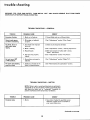
trouble
shooting
WARNING:
FOR
SOURCE OUTLET
YOUR OWN SAFETY,
TURN SWITCH
BEFORE TROUBLE SHOOTING.
"OFF"
TROUBLESHOOTING-
TROUBLE
AND
ALWAYS
REMOVE
PLUG FROM
GENERAL
PROBABLE CAUSE
REMEDY
Excessive vibration.
1. Blade out of balance.
1. Discard Blade and use a different blade.
Cannot make square
cut when crosscutting.
1. Miter gage not adjusted
1. See "Adjustments"
Cut binds, burns or
stalls motor when
1. Dull blade with improper
ripping.
2. Blade is Heeling.
2. See "Adjustments"
3. Warped board.
3. Make sure concave or hollow side is facing
"down," feed slowly.
4. Rip fence not properly
4. See "Adjustments"
section "Rip
1. See "Adjustments"
section "Blade Tilt".
properly.
POWER
section "Miter
Gauge".
"
1. Check set and sharpnessof blade.
tooth set.
section, "Heeling Adjustments
Fence".
aligned.
Cut not true at 90 °
or 45 ° positions.
Tilt crank and elevating
crank turn hard.
1. Stop collars not properly
adjusted.
1. Sawdust on threads of tilt
1. See "Maintenance
and Lubrication" section,
screw or elevating screw.
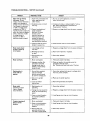
TROUBLE
SHOOTING
-- MOTOR
NOTE: Motors used on wood-working tools are particularly
susceptible to the accumulation of sawdust and wood chips
and should be blown out or "vacuumed"
frequently to
prevent interference with normal motor ventilation.
TROUBLE
Excessive noise.
PROBABLE CAUSE
REMEDY
1. Motor.
1. Have motor checked by qualified service
technician. Repair service is available at
your nearest Sears store.
Continued on next page.
22
TROUBLESHOOTING- MOTOR(continued)
TROUBLE
Motor fails to develop
full power. (Power
output of motor decreases
rapidly with decrease in
voltage at motor terminals.
For example, a reduction
of 10% in voltage causes
a reduction of 19% in
maximum power output of
which the motor is capable,
while a reduction of 20%
in voltage causesa
reduction of 36% in
maximum power output.)
Motor starts slowly
or fails to come up
to full speed.
PROBABLE CAUSE
REMEDY
1. Power line overloaded
lights, appliances
other motors.
2. Undersize
with
1. Do not use other appliances
when using the saw.
and
wires or circuit
2. Increase wire sizes, or reduce length of wiring.
See "Motor
Specifications
and Electrical
Requirements"
Section.
too long.
3. General overloading of
power company
facilities. (In some
sections of the
cOuntry, demand for
electrical power may
exceed the capacity
of existing generating
and distribution systems,)
3. Request
4. Incorrect fuses or circuit
breaker in power line.
4. Install
1. Low voltage will not
trip relay.
1. Request
2. Windings
2. Have motor
burned
or motors
out
a voltage check from
correct
fuses or circuit
a voltage check from
repaired
the power
company.
breakers.
the power
company.
or replaced.
or open.
Motor
overheats.
Starting relay in
motor will not
operate.
Motor stalls
(resulting in blown
fuses or tripped
circuit breakers),
3. Starting
relay not
operating.
3, Have relay replaced,
1. Motor
1. Feed work slower into blade.
overloaded.
2. Improper cooling. (Air
circulation restricted
through motor due to
sawdust, accumulating
inside of saw).
2. Clean
1. Burned
(due to
hold-in
by low
1. Have relay replaced and request
from the power company.
out sawdust to provide normal air
circulation
through motor.
See "Maintenance
and Lubrication"
Section.
relay contacts
extended
periods caused
line voltage,etc.)
a voltage check
2. Saw not in upright
position.
2. Place saw in upright
3. Loose or broken
connections.
3. Have wiring
1, Starting
relay not
operating.
!. Have relay replaced.
2. Voltage too low to permit
motor to reach operating
speed.
2. Request a voltage check from the power company.
3. Fuses or circuit breakers
do not have sufficient
3. Install
proper
position,
checked and repaired,
size fuses or circuit
breakers.
capacity.
Frequent opening of
fuses or circuit
breakers.
1. Motor overloaded.
1. Feed work slower into blade.
2, Fuses or circuit breakers
do not have sufficient
capacity.
2. Install proper size fuses or circuit breakers.
3. Starting relay not
operating (motor does
not reach normal speed).
3. Have relay replaced,
23
!
\
\
\
32
23
37
\
\
17
21
0
rrn
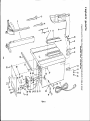
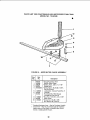
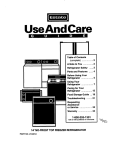
Figure
I
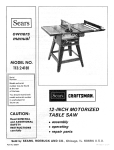
All parts illustrated
in Figures 1 through
5 and listed under part numbers may be ordered through any Sears retail mail order
store. Order parts by mail from the catalog order store which serves the territory
in which you live. In several instances, part
numbers are listed for COMPLETE
ASSEMBLIES.
All parts are shipped prepaid within
the limits of the continental
United
States.
WHEN ORDERING
ON THIS LIST:
REPAIR
PARTS,
ALWAYS
1, THE PART NUMBER
2. THE PART NAME
GIVE THE
FOLLOWING
INFORMATIONAS
3. THE MODEL NUMBER - 113.24140
4. THE NAME OF ITEM - 9-INCH MOTORIZED
SHOWN
TABLE
"10
SAW
-1
O_
r"
Always order by Part Number - not by Key Number
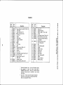
FIGURE
1
-N
"11
Key
No.
Part
No.
Key
No.
Description
O
Part
No.
Description
iiiii
1
62418
62070
1o
3
4
_
3540
63062
7
37911
30505
119264
_
10
11
12
13
14
2447
62417
37858
109093
62448
62449
60089
15
16
138167
115120
17
18
19
20
21
62441
37818
62333
60045
115998
Fence Assembly,
Rip
(See Figure 3)
Gage Assembly,
Miter
(See Figure 4)
Wrench, Arbor
Wrench, Shaft
Wrench, Hex "L" 3/16
Wrench, Hex "'L'" 1/8
Screw, Flat Hd. 10-32 x 5/8
Insert
Guard Assy. (See Figure 5)
Screw, Wing
*Carriage Bolt, I/4-20
x 1-3/4
Bracket
Clamp, Spreader
*Washer, Plain,
!7/64 x 7/16 x 1/32
*Lockwasher,
Internal
*Nut, Hex,
1/4-20 x 7/16 x 3/16
Cord with Plug
Relief, Strain
Crank Assembly,
Ring, Retaining
*Nut, Hex 8-32
Tooth
w/Set
Screw
1/4
22
23
24
138166
115545
448033
25
62430
26
27
28
29
30
63467
62267
62442
60256
448001
31
32
62443
9426307
33
34
35
36
37
-
448013
62452
436753
62444
115999
62455
62446
*Lockwasher,
Internal
Tooth
*Lockwasher,
Internal
Tooth
*Screw, Pan Hd.Type
23,
10-32 x 3/8
• Motor and Control
Box
(See Figure 2)
Cap - Flag Term
Clip, Capacitor
Switch, Locking
Key, Switch
*Screw, Type 23, Pan SI.
6-32 x 1/4
Panel, Front
*Screw, Pan Hd.o Type B,
No. 8 x 1/2
*Screw,
Pan Hd.,8-32 x 1/2
Clamp, Relay
*Screw,Pan
Hd.,10-32
x 3/4
Bar, Fence Guide
*Nut, Hex 10-32
Bag of Loose Parts
(not illustrated)
Owners Manual
(not illustrated)
Standard
Hardware
Item - May be Purchased
Locally.
Any
attempt
to
repair
this
motor
may
create
a
HAZARD
unless repair is done by a qualified
service
technician.
Repair service is available
at your
nearest
Sears Store.
No.8
No.10
m_:
r-_>
ZZ
o,_
_0
O-t
0
m
-t
r'm
"0
Q
me
•_
3>
ANY
ATTEMPT
TO
REPAIR THIS MOTOR
MAY CREATE A HAZARD
IS DONE BY QUALIFIED
19
UNLESS REPAIR
SERVICE TECHNICIAN,
REPAIR SERVICE IS AVAILABLE
NEAREST SEARS STORE.
6
\
30,
16
24
-.t
-rl
0
34.
31 32 3
23
AT YOUR
-.I
cn
r-
7
8
_J
o'n -I
CJcn
mE:
3
r"3>
ZZ
._.0
o.-i
0
13
14 15 14 18
17
7
16
N
m
-1
14 15 14
co
F
m
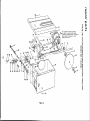
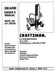
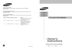
Figure 2
"0
Q
-l,
FIGURE
Key
No.
Part
No.
1
2
3
4
5
6
7
8
9
10
11
12
13
14
15
16
17
18
19
805297-1
62425
60302
62430
62434
60303
37900
62431
62445
60169
6362
62440
448035
62437
62306
60012
115545
115999
448011
20
21
62439
436753
2
Key
No.
Description
"o
Part
No.
Description
O_
*Screw,
Socket
Table,
Flat Hd.5/16-18x1-1/4
Saw
Ring, Retaining
7/16
• Motor and Control
Box
Nut,
Pivot
Spacer
Collar,
Stop
Support,
Collar
22
23
24
25
26
27
28
62438
62432
60031
62433
138167
443507
423350
29
102570
Spreader
t Blade
Nut, Arbor
Base
*Screw,Pan
Retainer,
Hd.10-32
x 1/2
Bearing
Bearing
Nut, Lock
*Lockwasher,
*Nut,
lnternal
Tooth
Hex 10-32
*Screw, Pan Hd.,Type
8-32 x 3/8
Indicator,
Bevel
*Screw, Pan Hd.,10-32
23
No. I 0
30
31
32
33
34
35
36
37
38
39
40
62436
60304
62427
62435
30613
62429
62426
60301
62426
62456
62458
r-
Screw, Tilt
Support,
Washer,
Bearing
.440 x 11/16
*Screw,
nternal
Mach.,Hex
x 3/8
Ring, Retaining
Hanger
Washer,
3/8
x 3/4
Hd./Ext.
Elevation
O.-n
-I
0o_
rn_
o,_
_z
Rod, Cradle
Washer, Spring
¢)
_('-)
Thrust
Ring, Retaining
Cradle
1/4
r;m
zz
Clamp, Cord
Rod, Motor
Screw,
Tooth
Hex Soc. Cup Pt.
Set, 1/4-20
Nut
"11
Hd.1/4-20
*Screw, Seres Ind.Hex
Lockwasher
*Screw,
x 1/32
O
Clamp
* Lockwasher,I
o--t
3/8
o
N
m
0
-t
rm
* Standard Hardware Item - May be Purchased Locally.
• Any
attempt to repair this motor may create a
HAZARD unless repair is done by a qualified service
technician. Repair service is available at your nearest
Sears Store,
t
Stock Item - May be secured through the hardware
departments of most Sears or Simpson-Sears Retail
Stores or Catalog Order Houses.
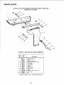
repair
parts
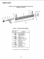
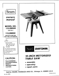
PARTS LIST FOR CRAFTSMAN
g-INCH MOTORIZED
MODEL NO. 113.24140
TABLE
SAW
10
3
1
4
2
13
14
FIGURE
Key
No.
--
3-
Part
No.
1
2
62418
62132
60067
3
4
5
6
7
62424
63011
62420
60050
131201
9
10
11
12
13
62419
62421
62131
62480
120399
14
62422
Standard
Description
Fence Assembly
60078
*
62418 RIP FENCE ASSEMBLY
Rip
Knob, Fence Adjusting
*Screw, Hex Soc.Cup
Pt. Set, I/4-20 x 1/4
Insert
Washer, Knob Clamp
Head, Fence
*Washer, .319 x 5/8 x 1/32
Lockwasher,
Internal Tooth
5/16
*Screw, Mach., Hex Hd.,
5/16-18
x 1/2
Channel, Fence
Bracket, Fence
Spring, Fence Adj.Shaft
Lock, Fence
*Nut, Square,
5/16-18 x 9/16 x 7/32
Hardware
Rod,
Fence
Item -
28
Lock
May be Purchased
Locally.
11 12
PARTS LIST FOR CRAFTSMAN
9-INCH MOTORIZED
MODEL NO. 113.24140
;TABLE SAW
@
2
3
4
5
6
7
FIGURE
Key
No.
4-
Part
No.
--
62070
1
62068
2
60024
3:62014
4 9404365
138166
62042
62252
t
62070 MITER
8
124824
1_
2225
139325
GAUGE ASSEMBLY
Description
tGauge Assembly,
Miter
Handle, Miter Gauge
*Washer, Plain, .320 x 1 x 1/16"
Gauge, Miter
*Screw, Mach., No. 8-32 x 5/16",
Pan Hd. Slotted
Lockwasher,
I ndicator
Internal
Tooth
No. 8
Rod Assembly,
Miter Gauge
Includes Key Nos. 8 & 9
*Nut, Hex-5/16-18
x 1/2 x 3/16"
Stud, Clamp
*Screw, Set, 1/4-20 x 3/8",
Hex Socket Hd., Cone Pt.
Standard
Hardware
Item - May be Purchased Locally.
Stock Item - May be secured through
the hardware
departments
of most Sears or Simpson-Sears
Retail
Stores or Catalog Order Houses.
29
repair
parts
PARTS LIST FOR CRAFTSMAN
9-INCH MOTORIZED
MODEL NO. 113.24140
TABLE
SAW
2
5
3
6
e
8
\
9
10
11
FIGURE
5 -
Key
No.
Part
No.
--
62417
62415
60004
60128
62416
62413
62414
62409
62411
62136
62412
9414920
60208
62410
1
2
3
4
5
6
7
8
9
10
11
12
13
Standard
62417 BLADE GUARD
ASSEMBLY
Description
Guard
Guard
Assembly
Ring, Retaining
1/4
*Washer,17/64
x 5/8 x 1/32
Pin, Guard
Link, Guard
Pin, Link
Spreader
Spring, Pawl
Spacer, Pawl
Pawl
*Washer,17/64
Nut, Push
Pin
Hardware
x 5/8 x 1/16
Item - May be Purchased
3O
Locally.
Sears
CRRFTSMRN
owners
manual
9-INCH
TABLE
MO TORIZED
SAW
The Model Number will be found on a plate attached to your
saw, at the left-hand side of the base. Always mention the
Model Number when requesting service or repair parts for your
Table Saw.
MODEL NO.
113.24140
All parts listed herein may be ordered from Sears, Roebuck and
Co. or from Simpsons-Sears Limited, c/o Repair Parts Dept. 98.
When ordering parts by mail, selling prices will be furnished on
request, or parts will be shipped at current selling prices and
you will be billed accordingly.
WHEN ORDERING
REPAIR
FOLLOWING
INFORMATION:
HOW TO ORDER
REPAIR PARTS
PARTS,
ALWAYS
GIVE
1. PART NUMBER
3. MODEL NUMBER
113.24140
2. PART DESCRIPTION
4. NAME OF ITEM9 INCH MOTORIZED
TABLE SAW
THE
Your Sears merchandise takes on added value when you
discover that Sears has over 2000 Service Units throughout the
country.
Each is staffed
by Sears-trained,
professional
technicians using Sears approved parts and methods.
SEARS, ROEBUCK AND
Part No. 62446
CO., Chicago,
IL 60684
Form
U.S.A. and SIMPSONS-SEARS
No. SP3979-4
LIMITED,
Toronto
Printed in U.S.A.
10/74