1
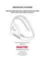
IMAGESAFE SCANNER
MICR READER AND DUAL-SIDED CHECK SCANNER
INSTALLATION AND OPERATION MANUAL
Manual Part Number: 99875472-3
MARCH 2010
REGISTERED TO ISO 9001:2008
1710 Apollo Court
Seal Beach, CA 90740
Phone: (562) 546-6400
Tech Support: (888) 624-8350
www.magtek.com
Copyright© 2007 - 2010
MagTek®, Inc.
Printed in the United States of America
Information in this document is subject to change without notice. No part of this document
may be reproduced or transmitted in any form or by any means, electronic or mechanical,
for any purpose, without the express written permission of MagTek, Inc.
MagTek is a registered trademark of MagTek, Inc.
ImageSafe™ is a trademark of MagTek, Inc.
MagnePrint® is a trademark of MagTek, Inc.
REVISIONS
ii
Rev Number
1.01
2.01
Date
22 February 2010
22 February 2010
3.01
10 March 2010
Notes
Initial Release
Product Name Change
Requirements p.5 updated; Image
added section 2
LIMITED WARRANTY
MagTek warrants that the products sold pursuant to this Agreement will perform in accordance with MagTek’s
published specifications. This warranty shall be provided only for a period of one year from the date of the
shipment of the product from MagTek (the “Warranty Period”). This warranty shall apply only to the “Buyer” (the
original purchaser, unless that entity resells the product as authorized by MagTek, in which event this warranty
shall apply only to the first repurchaser).
During the Warranty Period, should this product fail to conform to MagTek’s specifications, MagTek will, at its
option, repair or replace this product at no additional charge except as set forth below. Repair parts and
replacement products will be furnished on an exchange basis and will be either reconditioned or new. All replaced
parts and products become the property of MagTek. This limited warranty does not include service to repair
damage to the product resulting from accident, disaster, unreasonable use, misuse, abuse, negligence, or
modification of the product not authorized by MagTek. MagTek reserves the right to examine the alleged defective
goods to determine whether the warranty is applicable.
Without limiting the generality of the foregoing, MagTek specifically disclaims any liability or warranty for goods
resold in other than MagTek’s original packages, and for goods modified, altered, or treated without authorization
by MagTek.
Service may be obtained by delivering the product during the warranty period to MagTek (1710 Apollo Court, Seal
Beach, CA 90740). If this product is delivered by mail or by an equivalent shipping carrier, the customer agrees to
insure the product or assume the risk of loss or damage in transit, to prepay shipping charges to the warranty service
location, and to use the original shipping container or equivalent. MagTek will return the product, prepaid, via a
three (3) day shipping service. A Return Material Authorization (“RMA”) number must accompany all returns.
Buyers may obtain an RMA number by contacting Technical Support at (888) 624-8350.
EACH BUYER UNDERSTANDS THAT THIS MAGTEK PRODUCT IS OFFERED
AS IS. MAGTEK MAKES NO OTHER WARRANTY, EXPRESS OR IMPLIED,
AND MAGTEK DISCLAIMS ANY WARRANTY OF ANY OTHER KIND,
INCLUDING ANY WARRANTY OF MERCHANTABILITY OR FITNESS FOR A
PARTICULAR PURPOSE.
IF THIS PRODUCT DOES NOT CONFORM TO MAGTEK’S SPECIFICATIONS, THE SOLE REMEDY
SHALL BE REPAIR OR REPLACEMENT AS PROVIDED ABOVE. MAGTEK’S LIABILITY, IF ANY,
SHALL IN NO EVENT EXCEED THE TOTAL AMOUNT PAID TO MAGTEK UNDER THIS AGREEMENT.
IN NO EVENT WILL MAGTEK BE LIABLE TO THE BUYER FOR ANY DAMAGES, INCLUDING ANY
LOST PROFITS, LOST SAVINGS, OR OTHER INCIDENTAL OR CONSEQUENTIAL DAMAGES ARISING
OUT OF THE USE OF, OR INABILITY TO USE, SUCH PRODUCT, EVEN IF MAGTEK HAS BEEN
ADVISED OF THE POSSIBILITY OF SUCH DAMAGES, OR FOR ANY CLAIM BY ANY OTHER PARTY.
LIMITATION ON LIABILITY
EXCEPT AS PROVIDED IN THE SECTIONS RELATING TO MAGTEK’S LIMITED WARRANTY,
MAGTEK’S LIABILITY UNDER THIS AGREEMENT IS LIMITED TO THE CONTRACT PRICE OF THIS
PRODUCT.
MAGTEK MAKES NO OTHER WARRANTIES WITH RESPECT TO THE PRODUCT, EXPRESSED OR
IMPLIED, EXCEPT AS MAY BE STATED IN THIS AGREEMENT, AND MAGTEK DISCLAIMS ANY
IMPLIED WARRANTY, INCLUDING WITHOUT LIMITATION ANY IMPLIED WARRANTY OF
MERCHANTABILITY OR FITNESS FOR A PARTICULAR PURPOSE.
MAGTEK SHALL NOT BE LIABLE FOR CONTINGENT, INCIDENTAL, OR CONSEQUENTIAL
DAMAGES TO PERSONS OR PROPERTY. MAGTEK FURTHER LIMITS ITS LIABILITY OF ANY KIND
WITH RESPECT TO THE PRODUCT, INCLUDING ANY NEGLIGENCE ON ITS PART, TO THE
CONTRACT PRICE FOR THE GOODS.
MAGTEK’S SOLE LIABILITY AND BUYER’S EXCLUSIVE REMEDIES ARE STATED IN THIS SECTION
AND IN THE SECTION RELATING TO MAGTEK’S LIMITED WARRANTY.
iii
FCC WARNING STATEMENT
This equipment has been tested and was found to comply with the limits for a Class B digital device pursuant to
Part 15 of FCC Rules. These limits are designed to provide reasonable protection against harmful interference
when the equipment is operated in a residential environment. This equipment generates, uses, and can radiate radio
frequency energy and, if not installed and used in accordance with the instruction manual, may cause harmful
interference with radio communications. However, there is no guarantee that interference will not occur in a
particular installation.
FCC COMPLIANCE STATEMENT
This device complies with Part 15 of the FCC Rules. Operation of this device is subject to the following two
conditions: (1) this device may not cause harmful interference, and (2) this device must accept any interference
received, including interference that may cause undesired operation.
CANADIAN DOC STATEMENT
This digital apparatus does not exceed the Class B limits for radio noise from digital apparatus set out in the Radio
Interference Regulations of the Canadian Department of Communications.
Le présent appareil numérique n’émet pas de bruits radioélectriques dépassant les limites applicables aux appareils
numériques de la classe B prescrites dans le Réglement sur le brouillage radioélectrique édicté par le ministère des
Communications du Canada.
This Class B digital apparatus complies with Canadian ICES-003.
Cet appareil numériqué de la classe B est conformé à la norme NMB-003 du Canada.
CE STANDARDS
Testing for compliance with CE requirements was performed by an independent laboratory. The unit under test
was found compliant with standards established for Class B devices.
UL/CSA
This product is recognized per Underwriter Laboratories and Canadian Underwriter Laboratories 1950.
RoHS STATEMENT
When ordered as RoHS compliant, this product meets the Electrical and Electronic Equipment (EEE) Reduction of
Hazardous Substances (RoHS) European Directive 2002/95/EC. The marking is clearly recognizable, either as
written words like “Pb-free”, “lead-free”, or as another clear symbol ( ).
iv
SOFTWARE LICENSE AGREEMENT
IMPORTANT: YOU SHOULD CAREFULLY READ ALL THE TERMS, CONDITIONS AND RESTRICTIONS OF THIS
LICENSE AGREEMENT BEFORE INSTALLING THE SOFTWARE PACKAGE. YOUR INSTALLATION OF THE
SOFTWARE PACKAGE PRESUMES YOUR ACCEPTANCE OF THE TERMS, CONDITIONS, AND RESTRICTIONS
CONTAINED IN THIS AGREEMENT. IF YOU DO NOT AGREE WITH THESE TERMS, CONDITIONS, AND
RESTRICTIONS, PROMPTLY RETURN THE SOFTWARE PACKAGE AND ASSOCIATED DOCUMENTATION TO
THE ABOVE ADDRESS, ATTENTION: CUSTOMER SUPPORT.
TERMS, CONDITIONS, AND RESTRICTIONS
MagTek, Incorporated (the "Licensor") owns and has the right to distribute the described software and documentation,
collectively referred to as the "Software".
LICENSE: Licensor grants you (the "Licensee") the right to use the Software in conjunction with MagTek products.
LICENSEE MAY NOT COPY, MODIFY, OR TRANSFER THE SOFTWARE IN WHOLE OR IN PART EXCEPT AS
EXPRESSLY PROVIDED IN THIS AGREEMENT. Licensee may not decompile, disassemble, or in any other manner
attempt to reverse engineer the Software. Licensee shall not tamper with, bypass, or alter any security features of the software
or attempt to do so.
TRANSFER: Licensee may not transfer the Software or license to the Software to another party without the prior written
authorization of the Licensor. If Licensee transfers the Software without authorization, all rights granted under this Agreement
are automatically terminated.
COPYRIGHT: The Software is copyrighted. Licensee may not copy the Software except for archival purposes or to load for
execution purposes. All other copies of the Software are in violation of this Agreement.
TERM: This Agreement is in effect as long as Licensee continues the use of the Software. The Licensor also reserves the right
to terminate this Agreement if Licensee fails to comply with any of the terms, conditions, or restrictions contained herein.
Should Licensor terminate this Agreement due to Licensee's failure to comply, Licensee agrees to return the Software to
Licensor. Receipt of returned Software by the Licensor shall mark the termination.
LIMITED WARRANTY: Licensor warrants to the Licensee that the disk(s) or other media on which the Software is recorded
are free from defects in material or workmanship under normal use.
THE SOFTWARE IS PROVIDED AS IS. LICENSOR MAKES NO OTHER WARRANTY OF
ANY KIND, EITHER EXPRESS OR IMPLIED, INCLUDING, BUT NOT LIMITED TO, THE
IMPLIED WARRANTIES OF MERCHANTABILITY AND FITNESS FOR A PARTICULAR
PURPOSE.
Because of the diversity of conditions and PC hardware under which the Software may be used, Licensor does not warrant that
the Software will meet Licensee specifications or that the operation of the Software will be uninterrupted or free of errors.
IN NO EVENT WILL LICENSOR BE LIABLE FOR ANY DAMAGES, INCLUDING ANY LOST PROFITS, LOST
SAVINGS, OR OTHER INCIDENTAL OR CONSEQUENTIAL DAMAGES ARISING OUT OF THE USE, OR
INABILITY TO USE, THE SOFTWARE. Licensee's sole remedy in the event of a defect in material or workmanship is
expressly limited to replacement of the Software disk(s) if applicable.
GOVERNING LAW: If any provision of this Agreement is found to be unlawful, void, or unenforceable, that provision shall
be removed from consideration under this Agreement and will not affect the enforceability of any of the remaining provisions.
This Agreement shall be governed by the laws of the State of California and shall inure to the benefit of MagTek, Incorporated,
its successors or assigns.
ACKNOWLEDGMENT: LICENSEE ACKNOWLEDGES THAT HE HAS READ THIS AGREEMENT, UNDERSTANDS
ALL OF ITS TERMS, CONDITIONS, AND RESTRICTIONS, AND AGREES TO BE BOUND BY THEM. LICENSEE
ALSO AGREES THAT THIS AGREEMENT SUPERSEDES ANY AND ALL VERBAL AND WRITTEN
COMMUNICATIONS BETWEEN LICENSOR AND LICENSEE OR THEIR ASSIGNS RELATING TO THE SUBJECT
MATTER OF THIS AGREEMENT.
QUESTIONS REGARDING THIS AGREEMENT SHOULD BE ADDRESSED IN WRITING TO MAGTEK,
INCORPORATED, ATTENTION: CUSTOMER SUPPORT, AT THE ABOVE ADDRESS, OR E-MAILED TO
[email protected].
v
vi
TABLE OF CONTENTS
SECTION 1. OVERVIEW ............................................................................................... 1
FEATURES ............................................................................................................................................... 2
ACCESSORIES ........................................................................................................................................ 2
SPECIFICATIONS .................................................................................................................................... 3
SECTION 2. INSTALLATION ........................................................................................ 5
REQUIREMENTS ..................................................................................................................................... 5
CABLING PROCEDURE .......................................................................................................................... 6
SECTION 3. OPERATION ............................................................................................. 9
CHECK READING PROCEDURE ............................................................................................................ 9
CARD READING PROCEDURE ............................................................................................................ 10
LED INDICATORS.................................................................................................................................. 11
CLEANING ............................................................................................................................................. 11
Opening the Unit................................................................................................................................. 12
Cleaning Check Path and Scan Bars ................................................................................................. 13
Closing the Unit .................................................................................................................................. 17
SECTION 4. TROUBLESHOOTING GUIDE................................................................ 19
REQUIREMENTS ................................................................................................................................... 19
SET-UP ................................................................................................................................................... 19
TROUBLESHOOTING............................................................................................................................ 19
APPENDIX A. CHECK READING ............................................................................... 25
E13-B CHARACTER SET ...................................................................................................................... 25
CMC-7 CHARACTER SET ..................................................................................................................... 25
SI
SII
SIII SIV
S5 ........................................................................................................... 25
CHECK LAYOUTS ................................................................................................................................. 26
MICR FIELDS ......................................................................................................................................... 27
1-Transit Field..................................................................................................................................... 27
2-On-Us Field ..................................................................................................................................... 28
3-Amount Field ................................................................................................................................... 28
4-Auxiliary On-Us Field ...................................................................................................................... 28
APPENDIX B. DEMO SOFTWARE AND USB DRIVERS ........................................... 29
vii
FIGURES
Figure 1-1.
Figure 2-1.
Figure 2-2.
Figure 2-3.
Figure 2-4.
Figure 2-5.
Figure 3-1.
Figure 3-2.
Figure 3-3.
Figure 3-4.
Figure 3-5.
Figure 3-6.
Figure 3-7.
Figure 3-8.
Figure 4-1.
Figure A-1.
Figure A-2.
ImageSafe Scanner and Dual-sided Scanner with MagneSafe Secure Reader ....................... 1
ImageSafe Component Identification ........................................................................................ 5
ImageSafe Cabling (U.S. Version) ............................................................................................ 6
ImageSafe Cabling (International Version) ............................................................................... 7
ImageSafe Connections ............................................................................................................ 7
ImageSafe Cable Clip ................................................................................................................ 8
Check Orientation - Insertion ..................................................................................................... 9
MagneSafe Reader Swipe ....................................................................................................... 10
Opening the Unit ...................................................................................................................... 12
Cleaning Check Path and Scan Bars ...................................................................................... 13
Activating the Cleaning Swab .................................................................................................. 14
Cleaning the First Scan Bar ..................................................................................................... 15
Cleaning the Second Scan Bar ............................................................................................... 16
Closing the Unit ....................................................................................................................... 17
Sensor Location ....................................................................................................................... 21
Personal Checks ..................................................................................................................... 26
Business Checks ..................................................................................................................... 27
TABLES
Table 1-1 ImageSafe Accessories ............................................................................................................... 2
Table 1-2. Specifications ............................................................................................................................... 3
Table 3-1. LED indicators............................................................................................................................ 11
Table A-1. CMC-7 Nonnumeric Characters ................................................................................................ 26
viii
SECTION 1. OVERVIEW
™
The ImageSafe Scanner is a single-feed MICR (Magnetic Ink Character Recognition) reader
and a dual-sided check scanner. In a single pass, the ImageSafe Scanner reads the MICR
characters at the bottom of a check and produces a digitized image of the entire check (front and
back). The characters and the image are then transmitted to a host device which is typically a PC.
The ImageSafe Scanner also offers an integrated MagneSafe™ secure card reader to secure card
based payment transactions by encrypting the encoded card holder date on debit, credit and gift
cards. The MagneSafe reader can be used with a magstripe card for 2-factor authentication
during web based financial transactions. The MagneSafe reader will auto-discriminate between
different card formats such as: ISO (International Standards Organization) or AAMVA
(American Association of Motor Vehicle Administrators).
Figure 1-1. ImageSafe Scanner and Dual-sided Scanner with MagneSafe Secure Reader
1
ImageSafe
FEATURES
The ImageSafe Scanner is equipped with the following features:
• Single check feed
• MICR reader with support for E13B and CMC7 fonts
• Automatic parsing of MICR fields: transit, account, etc
• Extensive list of formats to transmit MICR data
• Dual-sided scanning which allows complete images of both sides of a check to be captured
• Image rendition: black/white and grayscale
• Image resolution: 200 dpi
• Image files: TIFF 6.0, JFIF with EXIF tags, BMP
• Image compression: CCITT G4 or JPEG
• Ability to capture up to four images per check
• SHA1 digital signature for image file authentication
• MagneSafe secure card reader
• LED indicator to provide device status
• Cover swings open for easy access to check path and scan bars with no tools required
ACCESSORIES
The following is a list of available accessories for the ImageSafe Scanner:
Part Number
22350300
Description
USB 2.0 A-B BLK 6'
64300090
PWR SUPPLY-DESKTOP, 12VDC 1.5A, 120V (U.S. VERSION)
64300080
PWR SUPPLY-DESKTOP, 12VDC 1.5A, 240V (INT. VERSION)
96530028
SAMPLE CHECKS. PACK OF 5
97200033
CLEANING SWABS
22359069
DEMO SOFTWARE CD
22415101
CLIP-USB/PWR SUP CORDS
Table 1-1. ImageSafe Accessories
2
Section 1. Overview
SPECIFICATIONS
Table 1-2 lists the specifications for the ImageSafe Scanner.
Table 1-2. Specifications
Reference Standards
Power Input
Current
(Operating Idle)
MTBF
Document Speed
Document Size
Image Resolution
MICR fonts supported
Interface Options
Dimensions
Weight:
Connector:
Temperature
Operating
Storage
Humidity
Operating
Storage
Altitude
Operating
Storage
OPERATING
ANSI X9.27
12VDC, 1.5 Amp
300 mA
1.5 A Max
Electronics:
125,000 hours
Check Read Head: 1,000,000 passes
MSR Read head: 1,000,000 passes
10 ips
4"x 9" Maximum
3"x 2.625" Minimum
200 dpi
E13-B
CMC-7
USB 2.0 or USB 1.1
MECHANICAL
Length 9.0”, Width 3.9”, Height 6.0”
2.2 lbs.
USB B
ENVIRONMENTAL
0oC to 50oC (32oF to 122oF)
-30oC to 70oC (-22oF to 158oF)
10% to 90% non-condensing
Up to 100% non-condensing
0 -10,000 ft (0 - 3,048m)
0 - 50,000 ft (0 - 15240m)
3
ImageSafe
4
SECTION 2. INSTALLATION
Installation of the ImageSafe Scanner is described below figure 2-1 shows a cad being swiped
through the MagneSafe card reader.
Note: Install the ImageSafe software before connecting the ImageSafe Scanner to a computer.
Failure to perform this step will prevent the ImageSafe application from installing
properly.
Figure 2-1. ImageSafe Component Identification
REQUIREMENTS
The following items should be present in ImageSafe Scanner box and will be required for
installation:
•
•
•
•
ImageSafe Scanner
Hi-Speed USB Cable
Power Adapter
Installation software CD (optional)
5
ImageSafe
CABLING PROCEDURE
To connect the ImageSafe Scanner to a local computer locate the power and USB cables
contained in the box. Once the cables have been located perform the following steps:
1.
Connect the USB plug to the ImageSafe Scanner as shown in Figures 2-2 and 2-4.
2.
On the AC power adapter, connect the power plug to the device
3.
On the AC power adapter, connect the plug to wall outlet
4.
The LED indicator on the ImageSafe Scanner should turn on to a steady green. The
LED indicator on the ImageSafe Scanner is located on the slot where the check is first
inserted for reading (see figure 2.1). If the LED does not turn green refer to the LED
indication section.
Caution
Do not place the ImageSafe Scanner within 6 inches of a
computer monitor or power supply. These devices may cause
undesirable interference with the check reading operation.
Figure 2-2. ImageSafe Cabling (U.S. Version)
6
Section 2. Installation
Figure 2-3. ImageSafe Cabling (International Version)
Figure 2-4. ImageSafe Connections
Note: An optional strain relief clip can be installed to securely attach the USB and power supply
cable to the ImageSafe chassis. To install the clip insert the cables into the retaining clip
and then plug the clip with cables into the ImageSafe. Figure 2-5, indicates the correct
location for each cable.
7
ImageSafe
Figure 2-5. ImageSafe Cable Clip
8
SECTION 3. OPERATION
This section contains check/ card reading procedures, the LED indicator states and cleaning
procedures.
CHECK READING PROCEDURE
1.
Orient the check so the MICR line is down and the printed side faces the center of the
ImageSafe Scanner as indicated in Figure 3-1. For more information about the MICR
line refer to Appendix A.
2.
Place the check so the leading edge is in the open slot. Slide the check forward.
3.
When the ImageSafe Scanner detects the presence of the check, the motor will turn
on. At this time press the check forward until the unit grabs the check. When this
happens, release the check. The check will then be transported around the check path
and will exit through the other side.
4.
After the check is read, the ImageSafe Scanner will transmit the data as specified by
its configuration parameters.
5.
Remove the check.
Figure 3-1. Check Orientation - Insertion
9
ImageSafe
CARD READING PROCEDURE
1.
Orient the card so that the magnetic stripe is down and facing away from the logo on
the unit and toward the wide color stripe on the MagneSafe reader, as indicated in
Figure 3-2.
2.
Slide the card in one motion from the top of the unit down through the slot as
indicated in the illustration.
3.
After the card is read, the ImageSafe will transmit the data as specified by its
parameters.
Figure 3-2. MagneSafe Reader Swipe
10
Section 3. Operation
LED INDICATORS
Table 3-1 describes the LED indicator conditions for check and card reading operations. The
LED indicator is located below the slot where the check is first inserted for reading.
Table 3-1. LED indicators
LED INDICATOR
OFF
SOLID GREEN
BLINKING GREEN
BLINKING AMBER
SOLID RED
BLINKING RED
DESCRIPTION
Power off
Ready to process check or card
Ready to process check scan or card swipe
Collected data is valid and correct
Check is being processed
Error collecting data or data is invalid
Paper Jam
*Refer to “Section 4. Troubleshooting Guide.”
CLEANING
Clean the outside of the ImageSafe Scanner with a soft, damp cloth and wipe with a dry cloth.
Caution
To avoid damaging the read head, do not touch the inside of the check or card
paths with a wet cloth.
Use the Cleaning Swab, P/N 97200078, to clean the Scan Bars as shown and described in the
next section.
11
ImageSafe
Opening the Unit
To open the check path and gain access to the Scan Bars, grip the ImageSafe Scanner hold the
unit as shown in Figure 3-3. Press the access latch button with your thumb and the access door
will pop open.
Figure 3-3. Opening the Unit
12
Section 3. Operation
Cleaning Check Path and Scan Bars
1.
When the check path access door is open, as shown in Figure 3-4, check the path for
debris. To clean, turn the unit over and tap gently on the bottom.
Figure 3-4. Cleaning Check Path and Scan Bars
2.
Check the scan bars to ensure there is no build-up of ink or paper debris.
13
ImageSafe
3.
To clean the scan bars, use the cleaning swab, shown in Figure 3-5. Activate the swab
by bending the plastic tube until you hear a snap.
4.
Wait until the liquid moves into the sponge tip. It should be damp when touched.
Figure 3-5. Activating the Cleaning Swab
14
Section 3. Operation
5.
When the tip of the swab is damp, clean the first scan bar by wiping the swab up and
down the scan bar surface as indicated in Figure 3-6.
Figure 3-6. Cleaning the First Scan Bar
15
ImageSafe
6.
After cleaning the first scan bar, clean the second scan bar by again wiping the swab
up and down the scan bar surface as indicated in Figure 3-7.
Figure 3-7. Cleaning the Second Scan Bar
16
Section 3. Operation
Closing the Unit
1.
Hold the unit as shown in Figure 3-8. Push the rear access door closed with the right
hand while holding on the opposite side with the left hand.
2.
The unit is properly closed when the two panels are flush and the latch has "clicked"
into position.
Figure 3-8. Closing the Unit
17
ImageSafe
18
SECTION 4. TROUBLESHOOTING GUIDE
REQUIREMENTS
• Personal Computer.
• USB Interface Cable, Part Number: 22350300
• AC adapter, Part Number: 64300090 (U.S) or 64300080 (International)
• Sample checks, Part Number: 96530005.
SET-UP
1.
2.
3.
4.
Plug USB cable into the ImageSafe Scanner.
Plug the other end of the USB cable into the PC.
Power on the ImageSafe Scanner.
Start trouble-shooting procedure at Step 00.
TROUBLESHOOTING
00
Check LED
Check the status of the LED indicator:
◊ Off, continue to step 01.
◊ Green, continue to step 02.
◊ Blinking red, continue to step 07.
◊ Red, continue to step 12.
01
Check the Power to the ImageSafe Scanner
Possible causes for this problem are:
• AC adapter connection to outlet - make sure the AC adapter is securely connected to outlet
on the wall or power strip.
• AC adapter connection to ImageSafe Scanner - make sure the AC adapter is securely
connected to the power jack on the Cable.
• Power strip - if using a power strip, make sure the strip is connected to outlet on the wall and
the switch on the strip is turned on.
• AC adapter is defective - replace the AC adapter.
Determine if any of the conditions described above are true:
◊ If yes, rectify and continue to step 00.
◊ If no, continue to step 12.
02
Read a check
Read a check through the ImageSafe Scanner:
◊ If the check is transported all the way around the check path, continue to step 03.
19
ImageSafe
◊
◊
If the check gets "stuck" in the check path, continue to step 06.
If the motor does not turn on, continue to step 12.
03
Did PC receive data?
After the check is read, did the PC receive any data?
◊ If yes, continue to step 04.
◊ If no, verify that USB cable is connected
04
Analyze data
Analyze the data received by the PC:
◊ If the data is good, continue to step 10.
◊ If the data contains one or more '?', continue to step 05.
05
Read error
Possible causes for this problem are:
• Interference - the ImageSafe may be too close to a monitor, AC adapter or magnetic device.
Move the ImageSafe away from the source of interference.
• Printing problem - the check being read may not meet the requirements of the ANSI
Standards. Use one the sample checks provided by MagTek.
• Feeding the check - do not hold on to the check as it goes around the path. Release the check
immediately after the ImageSafe "grabs" it. Also, make sure that the front end is not tilted up
while the check is being read.
Determine if any of the conditions described above are true:
◊ If yes, rectify and continue to step 02.
◊ If no, continue to step 06.
20
Section 4. Troubleshooting Guide
06
Path is obstructed
Foreign debris obstructing the check path:
• Loose debris - power off the ImageSafe Scanner and refer to Section 3, Check Path Cleaning.
• Wedged debris - the debris is wedged in and cannot be removed with the procedure described
above.
Is the foreign debris removable?
◊ If yes, remove and continue to step 02.
◊ If no, continue to step 12.
07
Blocked sensor or data error
One of the sensors may be blocked by dust build-up or foreign debris (see Figure 4-1 for sensor
location) or an error occurred when the MICR\card data was read. To resolve the issue try
reinserting the check or re-swiping the card if this does not work process to the sensor.
Use canned air to clean the sensor if this does not work proceed with the steps below.
Power off the ImageSafe Scanner and then power on again, observe the LED indicator:
◊ If the LED indicator blinks red, continue to step 12.
◊ Any other LED indicator status, continue to step 00.
◊ If the LED indicator blinks red/green, continue to step 12.
◊ Any other LED indicator status, continue to step 00.
Figure 4-1. Sensor Location
21
ImageSafe
08
No MICR data detected
Possible causes for this problem are:
• No MICR characters - the ink used to print the MICR characters does not have magnetic
properties. Try one of the sample checks provided by MagTek.
• Feeding the check - When feeding the check, make sure that the MICR line is at the bottom
and the printed side of the check is facing the MagTek logo on the ImageSafe Scanner.
Determine if any of the conditions described above are true:
◊ If yes, rectify and continue to step 02.
◊ If no, continue to step 09.
09
Cable problem
Possible causes for this problem are:
• Loose connection - the cable connector on the PC or the ImageSafe Scanner may be loose.
Make sure that both connectors are tightly connected.
• Damaged cable - the connectors, pins or wires in the cable may be damaged. Replace cable.
Determine if any of the conditions described above are true:
◊ If yes, rectify and continue to step 02.
◊ If no, continue to step 12.
10
No problem found
The ImageSafe Scanner is operating properly. If you have additional concerns or requirements
please contact your MagTek representative.
11
Read Insta-Change check
Read Insta-Change check with the appropriate settings. Return to step 00. If condition persists,
continue to step 12.
22
Section 4. Troubleshooting Guide
12
Return ImageSafe Scanner to MagTek
Possible causes for this problem are:
• USB cable is not connected
• The computer is turned off
• Sensor board is damaged
• Power connection failure
The ImageSafe Scanner has a problem that needs further analysis, testing, and possibly repair.
Please contact the MagTek Help Desk at (888) 624-8350, and make arrangements to send the
unit back to MagTek. Include a detailed description of the problem.
23
ImageSafe
24
APPENDIX A. CHECK READING
The characters printed on the bottom line of commercial and personal checks are special. They
are printed with magnetic ink to meet specific standards. These characters can be read by a
MICRImage Reader at higher speeds and with more accuracy than manual data entry. Two
MICR character sets are used worldwide; they are: E13-B and CMC-7. The E13-B set is used in
the US, Canada, Australia, United Kingdom, Japan, India, Mexico, Venezuela, Colombia, and
the Far East. The CMC-7 set is used in France, Spain, other Mediterranean countries, and most
South American countries.
E13-B CHARACTER SET
The MICR font character set E13-B includes digits 0 through 9 and four symbols. The numbers
found on U.S. checks are of the E13-B character set. The numbers and symbols of E13-B are as
follows:
Transit symbol
Dash Symbol
On-Us Symbol
Amount Symbol
CMC-7 CHARACTER SET
The numbers and symbols of the CMC-7 character set are as follows:
SI
SII
SIII
SIV
S5
25
ImageSafe
The nonnumeric CMC-7 characters are translated by the ImageSafe Scanner as shown in Table
A-1.
Table A-1. CMC-7 Nonnumeric Characters
CMC-7 Character
MICRImage Reader
Output
A
B
C
D
E
SI
SII
SIII
SIV
SV
CHECK LAYOUTS
Personal checks with MICR fields are shown in Figure A-1. Business checks are shown in
Figure A-2. The digits 1 through 4 in the illustrations are described below under MICR Fields.
6.00”
2.75”
1
2
Figure A-1. Personal Checks
26
3
Appendix A. Check Reading
8.75”
3.67”
4
1
2
3
Figure A-2. Business Checks
MICR FIELDS
The numbers 1 through 4 refer to the numbers below the checks on the illustration and represent
the 4 MICR fields.
1-Transit Field
The Transit field is a 9-digit field bracketed by two Transit symbols. The field is subdivided as
follows:
• Digits 1-4
• Digits 5-8
• Digit 9
Federal Reserve Routing Number
Bank ID Number (American Banking Association)
Check Digit
27
ImageSafe
2-On-Us Field
The On-Us field is variable, up to 19 characters (including symbols). Valid characters are digits,
spaces, dashes, and On-Us symbols. The On-Us field contains the account number and may also
contain a serial number (Check number) and/or a transaction code. Note that an On-Us symbol
must always appear to the right of the account number.
3-Amount Field
The Amount field is a 10-digit field bracketed by Amount symbols. The field is always zerofilled to the left.
4-Auxiliary On-Us Field
The Auxiliary On-Us field is variable, 4-10 digits, bracketed by two On-Us symbols. This field
is not present on personal checks. On business checks, this field contains the check serial
number.
28
APPENDIX B. DEMO SOFTWARE AND USB DRIVERS
To install the ImageSafe Scanner USB drivers and Demo software follow the steps below:
1. Insert the installation software CD into your computer’s CD-ROM (or download software
directly from the MagTek website: www.magtek.com); the installation application will
automatically begin and the screen below will appear. Press [Next] to continue the
installation process.
29
ImageSafe
2. At the “Select Options” screen shown below check the options you wish to install and
press [Next] to proceed with the installation.
3. The next step in to select the software installation location. Press [Browse] to select a
location or press [Next] to except the default location and proceed with the installation.
30
Appendix B. Demo Software and USB Drivers
4. The ImageSafe software is now installed press [Finish] to complete the installation
process.
31
ImageSafe
Once the demo software has been successful loaded the ImageSafe demo program can be used.
To use the demo program, click on the Microsoft Windows Start button. Then navigate to the
demo program by clicking on: All Prorgams→MagTek→Excella and Excella STX→Demo
Program. When the Demo program is selected the window below will be shown.
Select ‘Excella MDX.MDX001” from the [Select Device] drop down menu as shown below and
press connect; the demo software is now ready to use simply insert a check or swipe a card.
32
Notes:
33