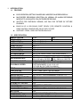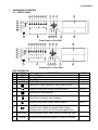
1
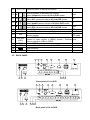
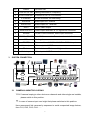
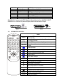
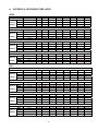
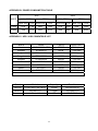
USER MANUAL
8/16 CHANNELS
DIGITAL VIDEO RECORDER
INSTRUCTION MANUAL
To obtain the best performance and ensure device function correctly, please read this
instruction manual carefully and completely.
INSTRUCTION MANUAL
To obtain the best performance and ensure device function correctly, please read this instruction manual
carefully and completely.
FCC Compliance
USER-INSTALLER CAUTION: YOUR AUTHORITY TO OPERATE THIS FCC VERIFIED EQUIPMENT
COULD BE VOIDED IF YOU MAKE CHANGES OR MODIFICATIONS NOT EXPRESSLY APPROVED BY
THE PARTY RESPONSIBLE FOR COMPLIANCE TO PART 15 OF THE FCC RULES.
NOTE: THIS EQUIPMENT HAS BEEN TESTED AND FOUND TO COMPLY WITH THE LIMITS FOR A
CLASS A DIGITAL DEVICE, PURSUANT TO PART 15 OF THE FCC RULES. THESE LIMITS ARE
DESIGNED TO PROVIDE REASONABLE PROTECTION AGAINST HARMFUL INTERFERENCE WHEN
THE EQUIPMENT IS OPERATED IN A COMMERCIAL ENVIRONMENT. THIS EQUIPMENT GENERATES,
USES, AND CAN RADIATE RADIO FREQUENCY ENERGY AND IF NOT INSTALLED AND USED IN
ACCORDANCE WITH THE INSTRUCTION MANUAL, MAY CAUSE HARMFUL INTERFERENCE TO
RADIO COMMUNICATIONS.
OPERATION OF THIS EQUIPMENT IN A RESIDENTIAL AREA IS LIKELY TO CAUSE HARMFUL
INTERFERENCE IN WHICH CASE THE USER WILL BE REQUIRED TO CORRECT THE INTERFERENCE
AT HIS OWN EXPENSE.
THIS CLASS A DIGITAL APPARATUS MEETS ALL REQUIREMENTS OF THE CANADIAN
INTERFERENCE-CAUSING EQUIPMENT REGULATIONS.
WARNINGS, CAUTIONS & COPYRIGHT
WARINGS
TO REDUCE THE RISK OF FIRE OR ELECTRIC SHOCK, DO NOT EXPOSE THIS PRODUCT TO RAIN OR
MISTURE.
DO NOT INSERT ANY METALLIC OBJECT THROUGH VENTILATION GRILLS.
CAUTION
CAUTION
RISK OF ELECTRIC SHOCK
DO NOT OPEN
CAUTION: TO REDUCE THE RISK OF ELECTRIC SHOCK.
DO NOT REMOVE COVER (OR BACK).
NO USER-SERVICEABLE PARTS INSIDE.
REFER SERVICING TO QUALIFIED SERVICE PERSONNEL.
Explanation of Graphical Symbols
The lightning flash with arrowhead symbol, within an equilateral triangle, is intended to alert
the user to the presence of insinuated "dangerous voltage" within the products enclosure
that may be of sufficient magnitude to constitute a risk of electric shock to persons.
The exclamation point within an equilateral rhombus is intended to alert the user to the
presence of important operating and maintenance (servicing) instruction in the literature
accompanying the product.
USERS OF THE SYSTEM ARE RESPONSIBLE FOR CHECKING AND COMPLYING WITH ALL FEDERAL,
STATE, AND LOCAL LAWS AND STATUTES COIPCERNING THE MONITORING AND RECORDING OF
VIDEO AND AUDIO SIGNALS. ULTRAK SHALL NOT BE HELD RESPONSIBLE FOR THE USE OF THIS
SYSTEM IN VIOLATION OF CURRENT LAWS AND STATUTES.
COPYRIGHT
THE TRADEMARKS MENTIONED IN THE MANUAL ARE LEGALLY REGISTERED TO THEIR
RESPECTIVE COMPANIES.
2
TABLE OF CONTENTS
WARNINGS, CAUTIONS & COPYRIGHT.........................................................................
TABLE OF CONTENTS.....................................................................................................
2
3
1
4
4
4
5
5
6
7
7
8
9
10
11
13
13
14
14
15
16
17
17
18
20
21
22
23
24
25
25
26
26
26
26
27
28
28
29
30
32
32
33
33
34
36
37
38
39
45
46
46
INTRODUCTION.........................................................................................................
1.1 FEATURE...........................................................................................................
1.2 SPECIFICATION................................................................................................
2 HARDWARE OVERVIEW...........................................................................................
2.1 FRONT PANEL...................................................................................................
2.2 BACK PANEL.....................................................................................................
3 SYSTEM CONNECTION............................................................................................
3.1 CAMERA & MONITOR LOOPING......................................................................
3.2 EXTERAL ALARM..............................................................................................
3.3 IR REMOTE CONTROL.....................................................................................
3.4 RS-232/485 CONTROLLER...............................................................................
3.5 PTZ (PAN, TILT AND ZOOM) CAMERA & JOYSTICK CONTROLLER.............
3.6 VGA OUTPUT.....................................................................................................
3.7 NETWORK.........................................................................................................
4 SYSTEM SETUP.........................................................................................................
4.1 SETUP MENU DIAGRAM..................................................................................
4.2 LIVE VIEWING...................................................................................................
4.3 SYSTEM SETUP................................................................................................
4.4 CAMERA SETUP................................................................................................
4.5 MOTION SETUP................................................................................................
4.6 RECORD SETUP...............................................................................................
4.7 ALARM SETUP..................................................................................................
4.8 EVENT LIST.......................................................................................................
4.9 HDD MANAGEMENT.........................................................................................
4.10 NETWORK SETUP............................................................................................
4.11 FIRMWARE UPDATE.........................................................................................
4.12 CDRW BACKUP................................................................................................
4.13 LOAD DEFAULT.................................................................................................
5 DVR PLAYBACK & USB BACKUP..............................................................................
5.1 PLAY TIME SEARCH.........................................................................................
5.2 EVENT LIST SEARCH.......................................................................................
5.3 LIVE VIDEO DURING PLAYBACK.....................................................................
5.4 USB BACKUP.....................................................................................................
6 BACKUP PLAYBACK..................................................................................................
6.1 MAIN SCREEN SETTING..................................................................................
6.2 CDRW / HDD BACKUP PLAYBACK..................................................................
6.3 USB & LOCAL BACKUP FILE PLAYBACK........................................................
6.4 BACKUP FILE TO AVI........................................................................................
6.5 LOCAL BACKUP................................................................................................
7
NETWORK VIEWING & PLAYBACK……………………………………………………..
7.1 SETUP IP ADDRESS ON PC SITE………………………………………………...
7.2 OPTIONAL MICROSOFT INTERNET EXPLORER SETTING………………….
7.3 LOGIN….............................................................................................................
7.4 LIVE VIEWING…...............................................................................................
7.5 PLAYBACK….....................................................................................................
7.6 CONFIGURE…..................................................................................................
APPENDIX A: RECORDING TIME LAPSE........................................................................
APPENDIX B: POWER COMSUMPTION TABLE..............................................................
APPENDIX C: HDD / USB COMPATIBLE LIST…..............................................................
V 2.40
3
19/MAY/2006
a11633RFMK09
1
INTRODUCTION
1.1 FEATURE
z
z
z
z
z
EASY OPERATION, SETTING CAN BE EASILY MODIFIED ON SCREEN DISPLAY.
MULTI-SPEED RECORDING SELECTION ON NORMAL OR ALARM RECORDING
MODE UP TO 120/100 (NTSC / PAL) PICTURES PRE SECOND.
SHUTTLE FOR FAST/SLOW VIEWING, JOG DIAL FOR PICTURE BY PICTURE
PLAYBACK.
BUILD-IN IR & RS-232/485 PORT READY FOR REMOTE CONTROL &
SUB-CONTROL PANELS ADD ON IN THE FUTURE.
SUPPORT CDRW, USB & NETWORK BACKUP.
1.2 SPECIFICATION
IMAGE SYSTEM
RESOLUTION-LIVE
VIDEO INPUT
VIDEO LOOPING
VIDEO OUTPUT
SPOT OUTPUT
AUDIO INPUT
AUDIO OUTPUT
STORAGE MEDIA
IMAGE FORMAT
RECORDING RATE
RECORDING MODE
PLAYBACK SPEED
TITLE
OSD & SETUP
ALARM INPUT
RELAY OUTPUT
RS-232 & RS-485 PORT
PTZ CONTROL
ETHERNET
IR REMOTE CONTROL
BACKUP
VGA OUTPUT
PASSWORD CONTROL
KEY LOCK
POWER INPUT
DIMENSIONS MM
RACK MOUNTABLE
NTSC
PAL
720×480
720×576
BNC × 8 / BNC x16
BNC × 8 / BNC x16
BNC × 1
BNC × 1
RCA × 1
RCA × 1
MAX 2 IDE HARD DISKS ( ONE REMOVABLE )
M-JPEG
720 x 240 up to 60 PPS
720 x 288 up to 50 PPS
320 x 240 up to 120 PPS 320 x 288 up to 100 PPS
MANUAL / ALARM / SCHEDULE
FAST FORWARD ×2 ×4 ×6 ×8 ×16 x32
FAST BACKWARD ×2 ×4 ×6 ×8 ×16
PICTURE BY PICTURE PLAYBACK
6 CHARACTERS FOR EACH CAMERA
TITLE / TIME / DATE / SETUP MENU
×9 / x16 N.O. OR N.C. PROGRAMMABLE
N.O. OR N.C. PROGRAMMABLE CONTACT ×1
YES
YES
YES
YES
USB, CDRW & NETWORK
OPTION
ONE FOR SYSTEM, ONE FOR HDD FORMAT
YES
AC 100-240V INPUT ( 47-63 HZ )
430(W) × 91(H) × 380(D)
EIA 19” 2U STANDARD MOUNTING RACK
4
a11633RFMK09
2
HARDWARE OVERVIEW
2.1 FRONT PANEL
5
6
7
8
9 10 11 12
REC
REW
STOP
PAUSE
PLAY
F.Fwd
Search
Water
Mark
ZOOM
1
2
3
4
5
6
7
8
15
16
23
17
1
2
POWER
3
H.D.D
REC
PLAY
4
MENU
25
AUTO
SEL
ENTER
COPY
24
14 19 20 21
13
18
22
Front Panel of 8-ch DVR
5
6
7
8
9 10 11 12
REC
REW
STOP
PAUSE
PLAY
F.Fwd
Search
Water
Mark
ZOOM
1
2
3
4
5
6
7
8
9
10
11
12
13
14
15
16
15
16
23
17
1
2
POWER
3
H.D.D
REC
PLAY
4
25
MENU
AUTO
SEL
ENTER
COPY
24
13
14 19 20 21
18
22
Front Panel of 16-ch DVR
DVR OPERATION
NO.
LABEL
1
POWER Power LED
2
Recording LED
REC
3
Play LED
PLAY
4
H.D.D LED
H.D.D
OPERATION
5
Press REC to start recording. Press again to stop.
6
Press the Rew button to play video backward.
7
Press Stop to stop playback
8
Press Pause to pause video playback
9
Press the Play button to play video forward.
10
Press F. Fwd to play video forward at high speed.
Press the button again the speed will be change
circulative from ×2,×4,×6,x8,x16 to the highest ×32.
11 Water Mark During playback press Water Mark to enable this mark.
12
ZOOM
During live viewing mode support 2x zoom in function.
5
PTZ
Zoom out
Zoom in
13
1-9 / 1-16 Press the button to display full screen.
Move downward or decrease the number.
Down
Select full/quad formats at 8/16-ch DVR model.
Move leftward or decrease the number
Left
Select 8/13 camera formats at 8/16-ch DVR model.
Move upward or increase the number.
Up
Select quad/9 camera formats at 8/16-ch DVR model.
Move rightward or increase the number
Right
Select 9/16 camera formats at 8/16-ch DVR model.
Press MENU to go into or exit main menu
PTZ setup
Press AUTO to switch channel by channel automatically. Auto Scan
Press this button to select the different assembled of Enter or exit
camera formats.
PTZ mode
Press ENTER button to make choose or move cursor
forward or make confirm in MENU system. / Backup Home
video or picture to USB or CDRW.
Slot for CDRW.
Location of installation for removable HDD.
USB connector
IR Sensor for remote control
14 ▼
15 ◄
16 ▲
17 ►
18
19
MENU
AUTO
20
SEL
21
ENTER/
COPY
22
23
24
25
CDRW
HDD
O
2.2 BACK PANEL
4
1
2
5
6
7
8
9
3
10
11
14 13 12
Back panel of 8-ch DVR
4
1
2
3
5
6
7
8
12 13 14
Back panel of 16-ch DVR
6
9
10
11
3
NO.
LABEL
OPERATION
1
VGA SETUP DIP
Setting Resolution & Frequency
2
VGA D-SUB OUT
Connect to CRT or LCD monitor.
3
ETHERNET
RJ-45 connector for networking.
4
AUDIO IN
5
AUDIO OUT
6
SPOT
7
MONITOR OUT
8
ALARM
9
RS-232 / RS-485
10
FAN
11
POWER
12
Video output
13
75 ohm
14
Video input
Audio input for 1 channel
Audio output for 1 channel
SPOT Video output
Video output with BNC & Y/C signal Din connector.
25 pin D-Sub connector. Alarm input connector.
9 pin D-Sub connector. For external control of unit.
Cooling fan.
Power switcher: AC100V~AC240V / 47-63Hz input.
Video output with BNC connector.
Switch between 75 ohm and high resistance.
Video input with BNC connector.
SYSTEM CONNECTION
3.1 CAMERA & MONITOR LOOPING
75 Ω: If camera looping to other devices or channels and video single are instable,
please switch to this position.
∞: In case of camera input over bright that please switches to this position.
Here recommend link cameras by sequence to avoid unexpected image broken,
from CH1, CH2, CH3, CH4…….
7
3.2 EXTERAL ALARM
There are three types of alarms that the system can be configured to handle. They
are Motion detection Alarm, External Alarm and Video Loss Alarm.
Motion detection Alarm and External Alarm:
When motion detection or External Alarm was triggered, there are 5 possible
actions will be taken.
a. Changes recording speed as alarm recording speed.
b. Monitor will display corresponding full screen alarm channel, it will switch
automatic mode to manual mode if buttons pressing activity occurred in 5 seconds.
c. Relays can be activated by motion detection or external alarm when turning
on.
d. External alarm will be recorded in the event list. Motion detection can be set
to yes or no.
e. The camera title will be transformed into color of yellow when motion is
happening, “ALARM” text will show up when external alarm is triggered.
Video Loss Alarm:
The default setting of Video Loss alarm is enabled and cannot be changed.
Although buzzer action can be disabled, an ALM record will still be added to the
Event List that indicates the precise time of video loss.
25 PIN D-Sub connector is used for external alarm input. It will accept TTL/CMOS
type trigger signals where the 8ch & 16ch DVR alarm inputs will be set by signal
polarity. It also accepts contact type devices. For example, N.O. relay input, the
Alarm Polarity should set to LOW in the ALARM SETUP menu. For N.C. relay
input, the Alarm Polarity should set to HIGH in the ALARM SETUP menu.
Connector pins 1-16 are for TTL/CMOS compatible alarm signals or for connect
one side of the contact type devices. Connector pins 20-21 are for input signal
grounding or the remaining side of the contact type devices.
The alarm hold input accept TTL/COMS alarm signal as well as contract device.
The connector pin 22 connected to Alarm Reset. The Alarm Reset signal return
connects to ground pin (pin 20-21).
Alarm output is Relay Type, Pin 23 is Normal Close and Pin 25 is Normal Open.
These outputs can be used to control external devices.
8
D-SUB25
PIN
1-9, (1-16)
10-19, (17-19)
20, 21
22
23
24
25
DEFINE
Alarm 1-Alarm 9 (16) Camera alarm input
N/A
GND (connecting to ground)
Alarm Reset
Alarm output, N.C.
Relay COM
Alarm output, N.O.
EXAMPLE 1: Connect with PIR (Passive Infrared) device from ALARM1 INPUT.
EXAMPLE 2: A Normal off (Normal Open) alarm siren at Alarm Output.
EX1
EX2
3.3 IR REMOTE CONTROL
ITEM
AUTO
SEL
.REC
1-8/1-16
Press AUTO to switch channel by channel
automatically.
Press this button to select the different assembled
of camera formats.
Press REC to start recording & again to stop.
Press the button to select the channel for full
screen.
Fast backward
Picture by picture backward play
Picture by picture forward play
Fast forward
Play video forward
MODE
Change screen format
▲
Move upward or increase.
►
Move right or increase.
▼
Move downward or decrease.
◄
Move left or decrease.
To enter item or make choose.
MENU
To into or exit main menu
STOP
Stop the playback
9
3.4 RS-232/485 CONTROLLER
RS-232
RS-485
PIN
2
3
5
6
7
8
9
RXD TXD
DEFINE
RXD
TXD
GND
RXDA
RXDB
TXDZ
TXDY
Dome Cam 1
CH 1
ID 1
R+
RT+
T-
Dome Cam 2
CH 2
ID 2
D0+ D0- D1+ D1-
Dome Cam 3
CH 3
ID 3
A B A B
0 1 0 1
Data format
Data: 1 Byte / Parity: None / Start bit: 1 / Baud: 9600
Totally 3 bytes in data frame:
1. Byte=0x10
:Broadcasting DVR
Byte=0x80+ID Number
:Remote Control DVR (ID number range: 5~21)
2. Byte=Refer to below table
:Command for each key string
3. Byte=First byte plus Second byte :Command for confirm checksum
8-ch DVR
F.Rew
Picture
Rew
Picture
Fwd
F.Fwd
ENTER
SEL
1
3
5
7
9
16-ch DVR Command
F.Rew
0x38
Picture
0x3b
Rew
Picture
0x3d
Fwd
F.Fwd
0x3e
ENTER
SEL
1
3
5
7
9
11
13
15
8-ch DVR 16-ch DVR
Rew
Rew
Command
0x3a
STOP
STOP
0x3c
PLAY
PLAY
0x39
0x32
0x31
0x33
0x34
0x35
0x36
0x11
0x13
0x15
0x17
0x19
0x1b
0x1d
0x1f
10
AUTO
AUTO
0x37
2
4
6
8
2
4
6
8
10
12
14
16
0x12
0x14
0x16
0x18
0x1a
0x1c
0x1e
0x30
3.5 PTZ (PAN, TILT AND ZOOM) CAMERA & JOYSTICK CONTROLLER
Following diagram for DVR connect between PTZ camera & joystick controller, for
DVR to control PTZ camera please make sure the CAMERA ID, BANDRATE
(default at 9600 bps) and RS-485 cable, if link with joystick controller please
confirm your DVR ID number. Every DVR ID & the PTZ camera ID behind DVR
must be unique.
Up to 16CH
Up to 16CH
R+ R- T+ T-
R+ R- T+ T-
Dome Cam 4
CH 4
ID 4
Dome Cam 3
CH 3
ID 3
Dome Cam 2
CH 2
ID 2
Dome Cam 4
CH 4
ID 4
A B A B
0 1 0 1
R+ R- T+ T-
Dome Cam 3
ID 3
Up to 128 ID
D0+ D0- D1+ D1-
Dome Cam 3
CH 3
ID 3
Dome Cam 2
CH 2
ID 2
D0+ D0- D1+ D1-
Dome Cam 1
CH 1
ID 1
Up to 128 ID
Dome Cam 1
CH 1
ID 1
A B A B
D+ D- D+ D-
Dome Cam 2
ID 2
D+ D- D+ D-
A B A B
DVR 1
ID 1
DVR 2
ID 2
Dome Cam 1
ID 1
Up to 32 ID
DATA+
DATA11
PTZ SETUP & FRONT PLANE CONTROL
EXAMPLE :
A PTZ camera at channel 3 with PELCO-D, 9600bps.
1. Press the channel button 3 into full screen mode.
2. Press SEL and “PTZ” mark appear at left upper corner.
REC 2005/10/10 MON 12:00:00 50% 120P
PTZ
3. Press the MENU button into setup mode.
By ▲ or ▼ to switch item & by ◄ or ► to change SPEED/ PROTOCOL &
BAUD RATE.
REC 2005/10/10 MON 12:00:00 50% 120P
PTZ
PTZ SETUP
O
UP-DOWN SPEED: OOOOO
O
LEFT-RIGHT SPEED: OOOOO
O
AUTO SCAN SPEED: OOOOO
O
PROTOCOL TYPE: PELCO-D
O
BAUD RATE:
9600
4. Press the MENU button again back to PTZ control mode.
5. With following label to control PTZ camera.
NO. LABEL
14
▼
15
◄
16
▲
PTZ
Down
Left
Up
NO.
5
21
19
LABEL
PLAY
ENTER
AUTO
PTZ
Zoom in
Home
Auto Scan
Zoom out
Enter or exit
PTZ mode
17
►
Right
6
REW
9
MENU
PTZ setup
20
SEL
6. Press the SEL button quite to PTZ control mode.
12
3.6 VGA OUTPUT
VGA output is optional, please ensure that you have proper DVR model for VGA
out put installation. By D-SUB connecter to CRT or LCD monitor, DIP switch
definition & suggestion table as below:
Resolution
DIP1
DIP2
Frequency
DIP3
DIP4
640× 4 80
0
0
56Hz
0
0
800×600
0
1
60Hz
0
1
1024×768
1
0
70Hz
1
0
SXGA 1280×1024
1
1
75Hz
1
1
VG A
SVGA
XGA
DIP1
DIP2
DIP3
DIP4
Resolution
0
0
0
0
0
0
0
1
0
0
1
0
0
0
1
1
75
0
1
0
0
56
0
1
0
1
0
1
1
0
0
1
1
1
1
0
0
0
1
0
0
1
1
0
1
0
1
0
1
1
1
1
0
0
1
1
0
1
1
1
1
0
1
1
1
1
VGA
640×480
SVGA
800×600
Frequency
60
72
60
72
Monitor
15 inch or
below
15 inch or
below
75
XGA
1024×768
60
70
15~17 inch
75
SXGA
1280×1024
60
17 inch or
above
3.7 NETWORK
Before starting the network application software, please confirm the RJ-45 cable
has been connected, and then turn the power on.
DVR would check network connection status while DVR power on, thus without
network connection the network function will be disabled.
Please make sure your network environment enabled and RJ-45 cable been
connected, before DVR power up!
13
4
SYSTEM SETUP
4.1 SETUP MENU DIAGRAM
SETUP MODE
․SYSTEM SET
․CAMERA SET
․MOTION SET
․RECORD SET
․ALARM SET
․EVENT LIST
․HDD MANAGEMENT
․NETWORK SET
․FIRMWARE UPDATE
․CDRW BACKUP
․LOAD DEFAULT
․EXIT
EVENT LIST
NO YY/MM/DD
01 05/10/10
02 05/10/10
03 05/10/10
04 05/10/10
05 05/10/10
06 05/10/10
07 05/10/10
08 05/10/10
09 05/10/10
10 05/10/10
SYSTEM SETUP
․DATE FORMAT
․DATE
․TIME H:M:S
․AUTO SWITCH DWELL
․SPOT SETUP
․DATE AND TIME OSD
․SYSTEM TYPE
․KEYBARD LOCK
․ID NUMBER
․LANGUAGE SELECT
․PASSWORD MODE
․EXIT
[<]
[<]
[<]
[<]
[<]
[<]
[<]
[<]
[<]
[<]
MASTER PAGE : 001
HH:MM:SS CH TYPE
00:01:00 -- POWER
00:02:00 -- RECORD
00:03:00 01 V.LOSE
00:04:00 02 ALARM
00:05:00 03 MOTION
00:06:00 -- POWER
00:07:00 -- RECORD
00:08:00 01 V.LOSE
00:09:00 02 ALARM
00:10:00 03 MOTION
HDD MANAGEMENT
․OVERWRITE MODE
ON
․CAPACITY WARNING 20%
․HDD FORMAT SETUP [<]
․EXIT
DISK
CAPACITY
MASTER
80GB
SLAVE
NONE
LEFT RATIO
41%
NONE
CAMERA SETUP
․CAMERA
․DISPLAY
․RECORD
․BRIGHTNESS
․CONTRAST
․HUE
․COLOR
․CAMERA TITLE
․EXIT
CAM 01
ON
ON
50
50
50
50
01
MOTION SETUP
․CAMERA
․MOTION DETECT
․BUZZER
․SENSITIVITY
․AREA SETUP
․EXIT
CAM 01
ON
OFF
080
[<]
RECORD SETUP
․SCHEDULE RECORD
․NORMAL RECORD PPS
․ALARM RECORD PPS
․ALARM RECORD DWELL
․RECORD QUALITY
․AUDIO RECORD
․EXIT
NETWORK SETUP
․IP ADDR: 192.168.001.221
․GATEWAY: 192.168.001.254
․SUB NET: 255.255.255.000
․IP MODE: STATIC IP
․NETWORK ENV: LAN
․NETWORK CHANNEL ENABLE
[<]
․HTTP PORT: 80
․STRAME PORT: 5000
ALARM SETUP
BUZZER
․BUZZER/ALARM DWELL
․VIDEO LOSS ALARM
․AUDIBLE ALARM
․EXT.ALARM MODE
․ALARM DISPLAY MODE
․MOTION EVENT
RELAY
․EXT.ALARM RELAY
․VIDEO LOSS RELAY
․MOTION RELAY
․EXIT
FIRMWARE UPDATE
FIRMWARE UPDATE START
Y-M-D
2005/10/10
00:00:00
02 SEC
[<]
ENABLE
NTSC
OFF
01
ENGLISH
DISABLE
[<]
CDRW BACKUP
․START TIME SETUP [<]
START: 2005/10/04 00:00:00
END : 2005/10/04 02:00:00
․BACKUP CD SIZE: 000MB
․CLOSE CD/RW: YES
․ERASE CD/RW: NO
․BACKUP CDRW START [<]
14
OFF
30P/SEC
30P/SEC
10 SEC
HIGH
ON
05 SEC
ON
ON
N.C
DISABLE
OFF
ON
ON
ON
4.2 LIVE VIEWING
A. Status indicator:
To press ENTER key to switch live display indicator in the live viewing mode.
1
2
3
4
REC
O
O
TIME & DATE
O
O
O
O
CHANNEL ID
O
HDD STATUS & PPS
O
O
O
B. Quick playback search
During live viewing mode and press
search mode.
key into quick time search or event list
C. PTZ control:
A. Press the channel key in full screen mode.
B. Press SEL key into PTZ mode, and a yellow PTZ mark at right upper corner.
C. Press MENU key to setup PROTOCOL & BAUDRATE between DVR & PTZ.
D. Press direction key to control the PTZ camera.
E. Press SEL key to exit PTZ mode.
D. Channel AUTO switch
Press AUTO key system would into full screen auto switch mode, and press
AUTO key again back to normal screen.
E. Channel selection
During split channel mode the windows will be limited, thus using the SEL key to
switch others channel on the screen.
F. Zoom
Press ZOOM button to enable zoom in function by direction & enter key to
decide zoom in area, and press enter key again back to normal mode.
15
4.3 SYSTEM SETUP
SYSTEM SETUP
․DATE FORMAT
․DATE
․TIME H:M:S
․AUTO SWITCH DWELL
․SPOT SETUP
․DATE AND TIME OSD
․SYSTEM TYPE
․KEYBARD LOCK
․ID NUMBER
․LANGUAGE SELECT
․PASSWORD MODE
․EXIT
Y-M-D
2005/10/10
00:00:00
02 SEC
[<]
ENABLE
NTSC
OFF
01
ENGLISH
DISABLE
▲ or ▼ to change item
◄ or ► to change value
A. DATA FORMAT
By ◄ or ► to switch Y-M-D, M-D-Y or D-M-Y mode.
B. DATE
By ▲ or ▼ to switch item & by ◄ or ► to change value.
C. TIME
By ▲ or ▼ to switch item & by ◄ or ► to change value.
D. AUTO SWITCH DWELL
By ◄ or ► to change volume.
E. SPOT SETUP
Press ENETR into SOPT STEUP mode or MENU to exit,
By ▲ or ▼ to switch item & by ◄ or ► to change value.
F. DATE AND TIME OSD
By ▲ or ▼ to switch item & by ◄ or ► to change value.
G. SYSTEM TYPE
By ◄ or ► to change value between NTSC / PAL / EIA / CCIR.
The DVR would switch system type automatically, after press MENU key.
H. KEYBOARD LCOK
By ◄ or ► to change value between OFF / TYPE1 / TYPE 2.
TYPE 1: Block all function but channel switch.
TYPE 2: Block all function.
After KEYBOARD LCOK mode setup, please setup the PASSWORD !
If without password, the un-authorized user would access into SYSTEM
SETUP and remove keyboard lock function easily!
I. ID NUMBER
By ◄ or ► to change value.
This ID number identifies the DVR location between DVR & remote controller or
joystick controller.
J. LANGUAGE SELECT
By ◄ or ► to change OSD language.
K. PASSWORD MODE
By ▲ or ▼ to switch item & by ◄ or ► to change value.
Default password number is "1111".
16
4.4 CAMERA SETUP
CAMERA SETUP
․CAMERA
․DISPLAY
․RECORD
․BRIGHTNESS
․CONTRAST
․HUE
․COLOR
․CAMERA TITLE
․EXIT
CAM 01
ON
ON
50
50
50
50
01
▲ or ▼ to change item
◄ or ► to change value
A. CAMERA
By ◄ or ► to change camera channel.
B. DISPLAY
By ◄ or ► to change value for this camera would display on screen or not.
C. RECORD
By ◄ or ► to change value for this camera would include with the recording or
not.
D. BRIGHTNESS
By ◄ or ► to change brightness level.
E. CONTRAST
By ◄ or ► to change contrast level.
F. HUE
By ◄ or ► to change HUE level.
G. COLOR
By ◄ or ► to change color level.
H. CAMERA TITLE
By ▲ or ▼ to switch item & by ◄ or ► to change wording.
4.5 MOTION SETUP
MOTION SETUP
․CAMERA
․MOTION DETECT
․BUZZER
․SENSITIVITY
․AREA SETUP
․EXIT
CAM 01
ON
OFF
080
[<]
▲ or ▼ to change item
◄ or ► to change value
A. CAMERA
By ◄ or ► to change value for camera motion setup.
B. MOTION DETECT
By ◄ or ► to change value for motion detect function.
C. BUZZER
By ◄ or ► to change value for buzzer or not while motion detected.
D.SENSITIVITY
By ◄ or ► to change sensitivity value from 001 (min) to 100 (max).
E. AREA SETUP
Press ENTER key to enter motion area setting.
1. Press direction key to select which block need to change.
2. Press AUTO to add a line to motion detection.
3. Press SEL to remove a line to motion detection.
4. Press MENU key to quit motion detection area setup.
17
4.6 RECORD SETUP
RECORD SETUP
․SCHEDULE RECORD
․NORMAL RECORD PPS
․ALARM RECORD PPS
․ALARM RECORD DWELL
․RECORD QUALITY
․AUDIO RECORD
․EXIT
OFF
30P/SEC
30P/SEC
10 SEC
HIGH
ON
▲ or ▼ to change item
◄ or ► to change value
A. SCHEDULE RECORD
By ◄ or ► to change value for schedule recording function.
A1.SCHEDULE RECORD SETUP
While SCHEDULE RECORD at ON, press ENTER key into SCHEDULE
RECORD diagram.
RECORD SETUP
WEEKDAY: MON-FRI
START-STOP TYPE
01-00
[X]
00-01
[0]
WEEKEND: SAT-SUN
START-STOP TYPE
ALL-TIME [X]
PPS
30P
ALM PPS
60P
30P
60P
PPS
30P
ALM PPS
60P
▲ or ▼ to change item
◄ or ► to change value
EXIT
A1.1
WEEKDAY & WEEKEND
The week days separated into 2 area weekday & weekend.
EXAMPLE 1:
If weekday are from Monday to Friday, thus the weekend must be Saturday to
Sunday.
EXAMPLE 2:
If weekday are from Wednesday to Friday, thus the weekend must be Saturday
to Tuesday.
EXAMPLE 3:
If weekday are from Monday to Wednesday, thus the weekend must be
Wednesday to Sunday.
MON
EX1
EX2
EX3
TUE
WEB
THU
FRI
SAT
SUN
WEEKDAY
WEEKEND
WEEKEND
WEEKDAY
WEEKEND
WEEKDAY
WEEKEND
18
A1.2
START-STOP
The 24 hours can be ALL TIME & separated hour's mode.
ALL TIME
Using the same recording type & PPS in whole day.
Separated hour's
As like weekday & weekend setting, every 24 hours can be separated 2 areas.
EXAMPLE 1:
Business hours form 8am-16pm, and 16pm-8am off.
EXAMPLE 2:
Business hours form 10am-20pm, and 20pm-10am off.
2
EX1
EX2
4
8
OFF
OFF
6
10
12
14
16
18
BUSINESS HOURS
BUSINESS HOURS
20
22
24
OFF
OFF
A1.3
TYPE
By ◄ or ► to change recording type mode.
A
O
X
Alarm recording only.
Full time recording.
No recording.
A1.4
PPS
By ◄ or ► to change normal recording picture pre second.
A1.5
ALM PPS
By ◄ or ► to change alarm recording picture pre second.
NTSC 120 / 60 / 30 / 15 / 10 / 5 / 3 / 2 / 1 PPS.
PAL 100 / 50 / 25 / 12 / 10 / 5 / 3 / 2 / 1 PPS.
Even the camera RECORD been turn off from CAMERA SETUP, during
120/100 PPS mode system would sharing PPS to each channel automatically.
B. NORMAL RECORD PPS
By ◄ or ► to change how many picture pre second in normal recording.
C. ALARM RECORD PPS
By ◄ or ► to change how many picture pre second in alarm recording.
D. ALARM RECORD DWELL
By ◄ or ► to change how many second recording while alarm occurs.
E. RECORD QUALITY
By ◄ or ► to change recording quality for LOW / MEDIUM / HIGH / BEST.
F. AUDIO RECORD
By ◄ or ► to decide included with audio recording or not.
19
4.7 ALARM SETUP
ALARM SETUP
BUZZER
․BUZZER/ALARM DWELL
․VIDEO LOSS ALARM
․AUDIBLE ALARM
․EXT.ALARM MODE
․ALARM DISPLAY MODE
․MOTION EVENT
RELAY
․EXT.ALARM RELAY
․VIDEO LOSS RELAY
․MOTION RELAY
․EXIT
05 SEC
ON
ON
N.C
DISABLE
OFF
▲ or ▼ to change item
◄ or ► to change value
ON
ON
ON
BUZZER
A. BUZZER/ALARM DWELL
By ◄ or ► to change how many second buzzer while alarm occurs.
B. VIDEO LOSS ALARM
By ◄ or ► to change value for video loss alarm.
C. AUDIBLE ALARM
By ◄ or ► to change value for audible alarm.
D. EX. ALARM MODE
By ◄ or ► to change value for external alarm device.
N.C: For Normal Close device as like infrared detecter.
N.O: For Normal Open device as like alarm siren or etc.
E. ALARM DISPLAY MODE
By ◄ or ► to change value for alarm display mode.
F. MOTION EVENT
By ◄ or ► to change value for adds the detected motion into event list or not.
RELAY
G. EXT. ALRAM RELAY
By ◄ or ► to change value for triggered the relay from external alarm device.
H. VIDEO LOSS REPLAY
By ◄ or ► to change value for triggered the relay while video loss occurs.
I. MOTION RELAY
By ◄ or ► to change value for triggered the relay if motion been detected.
20
4.8 EVENT LIST
EVENT LIST
NO YY/MM/DD
01 05/10/10
02 05/10/10
03 05/10/10
04 05/10/10
05 05/10/10
06 05/10/10
07 05/10/10
08 05/10/10
09 05/10/10
10 05/10/10
MASTER PAGE : 001
HH:MM:SS CH TYPE
00:01:00 -- POWER
00:02:00 -- RECORD
00:03:00 01 V.LOSE
00:04:00 02 ALARM
00:05:00 03 MOTION
00:06:00 -- POWER
00:07:00 -- RECORD
00:08:00 01 V.LOSE
00:09:00 02 ALARM
00:10:00 03 MOTION
▲ or ▼ to change item
◄ or ► to change page
A. NO
By ▲ or ▼ to switch event item & by ◄ or ► to pages.
In the event list each hard disk would stored 2000 pieces event, with 2 hard
disks would be up to 4000 pieces, and header information bar would show the
event belong to which hard disk.
B. DD/MM/YY
The Year/Month/Day, Month/Day/ Year or Day/Month/Year depend on date
format from SYSTEM SETUP.
C. HH:MM:SS
The Hour/Minute/Second for event starts time of this event.
D. CH
Channel number, depend on what event type with specific channel.
E. TYPE
Following issues would list on event list.
POWER
RECORD
V.LOSE
ALARM
MOTION
If DVR been turn off, power up time would add on the list.
If the record bottom been pressed.
If a camera signal lose and channel number would on the list.
If alarms been triggered this event would on the list.
If motion been detected this event & channel would on the list.
21
4.9 HDD MANAGEMENT
HDD MANAGEMENT
․OVERWRITE MODE
ON
․CAPACITY WARNING 20%
․HDD FORMAT SETUP [<]
․EXIT
DISK
CAPACITY
MASTER
80GB
SLAVE
NONE
▲ or ▼ to change item
◄ or ► to change page
LEFT RATIO
41%
NONE
A. OVERWRITE MODE
By ◄ or ► to change value for overwrite or non-overwrite mode.
B. CAPACITY WARNING
By ◄ or ► to change the 20 / 15 / 10 / 5% for non-overwrite alarm.
C. HDD FORMAT SETUP
HDD FORMAT SETUP
․HDD PASSWAORD PROTECT ENABLE
․HDD PASSWORD
1111
․FORMAT
[<]
․EXIT
C-1. HDD PASSWORD PROTECT
By ◄ or ► to change value for hard disk format password protection
C-2. HDD PASSWORD
By ▲ or ▼ to change item & by ◄ or ► to change value.
Preset password: 1111
C-3. FORMAT
Press ENTER key into hard disk format diagram.
[ATTENTION]
WILL BE LOST ALL HDD-DATA
ARE YOU SURE?
․YES
․NO
By ◄ or ► to decide YES or NO, and press ENTER key to execute.
22
4.10 NETWORK SETUP
NETWORK SETUP
․IP ADDR: 192.168.001.221
․GATEWAY: 192.168.001.254
․SUB NET: 255.255.255.000
․IP MODE: STATIC IP
․NETWORK ENV: LAN
․NETWORK CHANNEL ENABLE
[<]
․HTTP PORT: 80
․STRAME PORT: 5000
▲ or ▼ to change item
◄ or ► to change page
A. IP ADDR
By ▲ or ▼ to switch item & by ◄ or ► to assign an IP address number.
B. GATEWAY
By ▲ or ▼ to switch item & by ◄ or ► to assign the gateway number.
C. SUB NET
By ▲ or ▼ to switch item & by ◄ or ► to assign the submask.
D. IP MODE
By ◄ or ► to change STATIC IP or DHCP.
E. NETWORK ENV
By ◄ or ► to change network environment.
CROSSOVER By crossover cable link to PC directly.
LAN
Link to Local Area Network environment.
WAN
Link to Wide Area Network / INTERNET environment.
F. NETWORK CHANNEL ENABLED
Press ENTER key into enabled the specific channel for network.
NETWORK CHANNEL SETUP
․ CH01
․ CH02
․ CH03
․ CH04
․ CH05
․ CH06
․ CH07
․ CH08
․ CH09
:
:
:
:
:
:
:
:
:
ON
ON
ON
ON
ON
ON
ON
ON
ON
▲ or ▼ to change item
◄ or ► to change page
G. HTTP PORT
By ▲ or ▼ to switch item & by ◄ or ► to change port number.
Preset at 80
H. STRAME PORT
By ▲ or ▼ to switch item & by ◄ or ► to change port number.
Preset at 5000.
23
4.11 FIRMWARE UPDATE
FIRMWARE UPDATE
FIRMWARE UPDATE START
[<]
Press ENTER to start firmware update, but please confirm following steps.
!!CAUTION!!
Please make sure your firmware mode & version!
Wrong version firmware would make system damaged!
Update steps:
1. Confirm the firmware must in the fold named "firmware",
and the fold within following file from the picture as below:
2. Plug the USB flash disk into USB connector.
3. Get into "FIRMWARE UPDATE" item & press ENTER to start update.
4. System would show “FIRMWARE UPDATING” while updating.
5. After updated the screen would show "PLEASE SYSTEM REBOOT",
and than please restart DVR.
24
4.12 CDRW BACKUP
CDRW BACKUP
▲ or ▼ to change item
◄ or ► to change page
․START TIME SETUP [<]
START: 2005/10/05 00:01:00
END : 2005/10/05 00:05:00
․BACKUP CD SIZE: 000MB
․CLOSE CD/RW: YES
․ERASE CD/RW: NO
․BACKUP CDRW START [<]
A. START TIME SETUP
Press ENTER key into START TIME SETUP diagram,
and by ▲ or ▼ to change number & by ◄ or ► to switch item,
press ENTER key again confirm the start time,
system would check the start time automatically and back to CDRW BAKCUP.
B. BACKUP CD SIZE
By ◄ or ► to decide backup size and the END time will changed automatically,
and every 1 minute would copy 2MB data into CD disk.
C. CLOSE CD/RW
By ◄ or ► to decide close the CD disk or not.
YES: Close CD R/W disk and can't write in any more.
System would block the inner ring on the disk, and no more data can't be write,
otherwise using CDRW disk & Erase Disk function.
NO: Keep CD R/W in writable status until disk full.
D. ERASE CD/RW
By ◄ or ► to decide close the CD disk or not.
YES: Erase all data on the CD R/W before START BACKUP.
System would remove all data on the CDRW disk, CD-R can't be.
NO: Keep all data on the disk and add new file on the CD R/W.
E. BACKUP CDRW START
Press ENTER to start CDRW backup.
If without CD disk in the CDRW recorder, please put the CD disk in and repress
the ENTER to start CDRW backup.
After backup finish CDRW recorder would eject automatically.
F. BACKUP FILE NAME
Each backup file will named as the time when backup, as like:
10061817.05 will be Oct 6th 18:17 channel 5.
4.13 LOAD DEFAULT
Press ENTER to load the system default setting, and "LOAD DEFAULT !" would
shown on the screen until restore finish.
25
5
DVR PLAYBACK
QUICK TIME SEARCH
During live viewing modes and press
PLAY or PB key into quick time search
mode, by ▲ or ▼ to enter search mode.
․ PLAY TIME SEARCH
․ EVENT LIST SEARCH
5.1 PLAY TIME SEARCH
PLAY TIME SEARCH
YYYY/MM/DD HH:MM:SS
2005/10/10 00:01:00
[MASTER HDD]
START TIME:
2005/10/01
END
TIME:
2005/10/10
[MASTER HDD]
START TIME:
2005/10/10
END
TIME:
2005/10/20
By ▲ or ▼ to switch item & by ◄ or ► to
change port number, and than press
ENTER key to start playback, press
LIVE back to live viewing.
00:00:00
00:00:00
00:00:00
00:00:00
5.2 EVENT LIST SEARCH
EVENT LIST
NO YY/MM/DD
01 05/10/10
02 05/10/10
03 05/10/10
04 05/10/10
05 05/10/10
06 05/10/10
07 05/10/10
08 05/10/10
09 05/10/10
10 05/10/10
MASTER PAGE : 001
HH:MM:SS CH TYPE
00:01:00 -- POWER
00:02:00 -- RECORD
00:03:00 01 V.LOSE
00:04:00 02 ALARM
00:05:00 03 MOTION
00:06:00 -- POWER
00:07:00 -- RECORD
00:08:00 01 V.LOSE
00:09:00 02 ALARM
00:10:00 03 MOTION
By ▲ or ▼ to switch item and press
ENTER key to start playback, press
LIVE back to live viewing.
5.3 LIVE VIDEO DURING PLAYBACK
During playback in
8CH or
13CH screen mode, the main channel would
show the live video and others in playback mode.
Switch live video channel: Press channel number.
Select others playback channel: Press SEL key.
26
5.4 USB BACKUP
Every USB flash disk powered with difference USB driver IC, here
compatible with most USB flash disk, please refer to APPENDIX C for USB
DISK support list, if meet incompatible issue.
BEFORE BACKUP
A. Press the USB disk volume into USB port in the live viewing mode
B. Get into playback mode by time search or event list search, and playing the
video.
VIDEO BACKUP
During multiplexer or single full channel mode press the COPY bottom at the time
point to start the backup, and press the COPY bottom again to stop backup, and
than system would saving video into USB disk.
PICTURE BACKUP
During single full channel mode pause the screen and press the COPY bottom,
and than system would saving the picture into USB disk.
BACKUPED FILE NAME
Each backup file will named as the time when backup, as like:
10061817.05 will be Oct 6th 18:17 channel 5.
AFTER BACKUP
After USB backup system would saving, the playback software “player.exe” to
playback.
27
6
BACKUP PLAYBACK
SYSTEM REQUIREMENT
CPU: Intel Pentium III 1G or above.
MEMORY: 512 MB or above.
VGA: 32MB/64MB or above.
OS: Microsoft Windows XP SP2 or above.
VGA RESOLUTION: 1024*768 or above.
6.1 MAIN SCREEN SETTING
A. MAIN SCREEN
USB & local backup playback
CDRW / HDD backup playback
Saving as AVI file
Video/Path/AVI Codec setting
Click on SETTING bottom into Network viewer setting & confirm following
item:
Video
Check the item for video size,
system & frame pre second.
AVI Codec
Pick a codec for the video
transform into AVI, each codec
with differ advantage, here
recommend for Microsoft or
Windows for must popular
usage.
.
28
6.2 CDRW / HDD BACKUP PLAYBACK
A. Insert the CD disk into CDROM, the software will auto pop out, and select
"ScanDisk" and pick the physical disk which CD disk inside.
B. Press the play icon to play the video.
29
6.3 USB & LOCAL BACKUP FILE PLAYBACK
A. Plug the USB disk into PC or check the local backup folder.
If using USB mode, please double click the player.exe from the pop-up diagram.
(As below)
B. The play backup program would appear on the screen, select "FilePlay" and
"Open".
30
C. Open the USB disk located driver letter. (Example F:) or the local backup folder,
and pick the file to playback.
The backup file will named as the time when backup, as like:
10061940.05 will be Oct 6th 19:40 channel 5.
D. Press the play icon to play the video or still picture.
31
6.4 BACKUP FILE TO AVI
A. During video playback mode and press AVI bottom following "AVI Save" dialog
will appear on the screen.
B. Make up a filename and path than press OK bottom to start AVI backup, and
the AVI transform indication would in green.
(Recommend check all camera channel box, system would neglect these
channels to backup if without video signal.)
6.5 LOCAL BACKUP
A. Before backup please click on SETTING bottom into Local record path.
Make up the location to save local backup file.
B. During video playback mode and press LOCAL bottom and the LOCAL
indication light would be in green.
32
7
NETWORK VIEWING & PLAYBACK
CPU: Intel Pentium III 1G or above.
MEMORY: 512 MB or above.
VGA: 32MB/64MB or above.
OS: Microsoft Windows XP SP2 or above.
VGA RESOLUTION: 1024*768 or above.
7.1 SETUP IP ADDRESS ON PC SITE
Install the machine inside the LAN internal network or utilize cross-over interlaced
network cable directly (in the accessories pack) and one computer to conduct
direct connection. This step is to set the IP position of the IP Cam by IPInsatller.
If Windows XP SP2 or above the security alert occur, please click on Unblock.
The IPInstallerEng.exe diagram will appear:
Attention: Please input correct network parameters. No space is allowed between
characters.
The Device lists on the left will list out all IP Cam on
LAN by Search Device button. When the equipment
is pointed by the mouse, the right side will show the
parameters of various networks. Various parameters
can be revised on it and by pressing the "Submit"
on the lower part; the revision will complete and
following diagram appear.
33
7.2 OPTIONAL MICROSOFT INTERNET EXPLORER SETTING:
OPTION 1: DISABLE ACTIVEX WARNING
A. IE Æ ToolsÆ Internet OptionsÆ SecurityÆ Custom LevelÆ Security SettingsÆ
Download unsigned ActiveX controls ÆEnabled or Prompt (recommend).
B. IE Æ ToolsÆ Internet OptionsÆ SecurityÆ Custom LevelÆ Security SettingsÆ
Initialize and script ActiveX controls not marked as safe ÆEnabled or Prompt
(recommend).
1
2
3
4
5
Above three options are all based on select as the prompt.
As indicated in the diagram. Please select "YES"
34
OPTION 2: ADD TO TRUSTED SITES
IE Æ ToolsÆ Internet OptionsÆ SecurityÆ Trusted sitesÆ Sites
35
7.3 LOGIN
A. INSTALL ACTIVEX
B. START INSTALL ACTIVEX
C. ACCOUNT & PASSWORD LOGIN
After setting up the IP based on the above step, connect to the intended network or
LAN. Execute IE directly on PC. Directly input IP to conduct on-line and following
User Management diagram occur and default administrator as below:
User name: admin
Password: admin
36
7.4 LIVE VIEWING
7.5 LIVE VIEWING
PTZ CONTROL PANEL
DVR CONFIGURATION
SAVE IMAGE
DIRECTLY TO AVI
SAVE FILM
REMOVE OSD EVENT
VIEWING STATUS
SYSTEM TIME
PLAYBACK
SCREEN FORMAT
z
PTZ CONTROL PANEL
After set the PTZ setting on DVR site, just click on the channel which went to
control, and using PTZ CONTROL PANEL to control PTZ camera.
z
DVR CONFIGURATION
Get into DVR network menu.
z
VIEWING STATUS
Blue for live viewing mode, Red for playback mode.
z
SYSTEM TIME
Live viewing mode: The current live viewing time.
Playback mode: The position of the playback.
z
SCREEN FORMAT
Screen split mode, and continuously click for difference channel set.
z
PLAYBACK
Get into playback mode.
z
RIGHT CLICK
- SAVE IMAGE
Saving current image as JPG picture.
- TO AVI DIRECTLY
Saving video to AVI compress from BMP file.
- CODEC TO AVI
Saving video from selected codec to AVI file.
- CLEAR EVENT
Remove OSD notification event.
37
7.6 PLAYBACK
Click on the
PLAYBACK icon get into playback menu.
ADJUST DATE POSITION
ADJUST TIME POSITION
START TIME SERACH PLAYBACK
LIST THE EVENT ITEMS
FROM DISK
DOUBLE CLICK ON THE
ITEM TO START EVENT
PLAYBACK
Using “PLAYBACK FUNCTION KEY” to change location, and with
back to living mode.
ONLIEW STATUS
PLAYBACK STATUS
38
STOP key
PLAYBACK FUNCTION KEY
7.7 CONFIGURE
A. SYSTEM / SYSTEM INFOMATION
z
SYSTEM INFORMATION
SERVER NAME: This name will show on the IP Installer.
LANGUAGE SETTING: There are English, Traditional Chinese, and Simple
Chinese to select. When change, it will show the following dialogue box for the
confirmation of changing language.
z
NTP SETTING
SET NTP SERVER: Synchronize with Network Time Protocol server from Port
123, after press Apply key.
B. SYSTEM / USER MANAGEMENT
39
User Management provides 3 layers: Administrator (highest), User & Anonymous
login.
Default administrator account:
Username: admin
Password: admin
z
ANONYMOUS USER LOGIN:
YES Accept anonymous user login without password as guest login.
NO Anonymous login unacceptable.
z
USER MANAGEMENT:
Add user: Key in HTTP Username, Password and than Add/Set key to save.
Modify user: Check the account want to modify from User list, modify on User
Management form directly and than Add/Set key to save.
Delete user: User name will list out names of all users. Very bottom side "admin"
is the highest level user and cannot be deleted. Others are general users. After it
is being pointed, press Delete key to delete.
C. SYSTEM / DOWNLOAD
z
After click on DOWNLOAD form left tool bar, system would pop out a dialogue
window for user to download NETVIEWER and named player.exe.
40
D. NETWORKING / IP SETTING
z
IP ASSIGNMENT
DHCP: Under Dynamic Host Configuration Protocol mode, your DHCP server
would update related setting automatically.
STATIC: Please key in IP Address, Subnet Mask & Gateway which depend on
network each environment differ.
Basically under same network environment only IP address different, but Subnet
Mask & Gateway must be same.
z
PORT ASSIGNMENT
Under NAT or related environment following port need to mapping for virtual server
setting need.
HTTP PORT: Defaulted as 80.
VIDEO PORT: Defaulted as 5000.
41
E. NETWORKING / FTP & MAIL
CHECK THE MAIL OR FTP BOX TO ENABLE NOTIFICATION FORM DVR ALARM
SIGNAL.
z
MAIL
MAIL SERVER: Email server address.
USERNAME: Account for email server.
PASSWORD: Password for email server.
SENDER MAIL: Sender Email address.
RECEIVER MAIL: Receiver Email address.
BCC MAIL: Blind Carbon Copy Email address.
EVENT SUBJECT: Email subject.
User able semicolon to separate receivers in the same field, just easily add up as
many receivers as you wish. For an example, below figure indicates 3 receivers
are in the receiving list.
EX: [email protected]; [email protected]; [email protected]
z
FTP
FTP SERVER: FTP server address.
USERNAME: Username for FTP upload account.
PASSWORD: Password for FTP uploads account.
PORT: FTP service port number defaulted as 21.
UPLOAD PATH: Default value is the root of FTP server if leave empty. Please
make sure you have write privilege.
42
F. NETWORKING / PPPoE
z
PPPoE SETTING
CHECK THE ENABLED BOX TO ENABLE ADSL DIAL UP FUNCTION.
USERNAME: Username for ADSL account.
PASSWORD: Password for ADSL account.
NEW IP ADDRESS WILL SHOW UP AT THE BUTTON LINE, WHILE DAIL UP
SUCCESSFULLY.
z
SEND MAIL AFTER DIALED
CHECK THE ENABLED BOX TO ENABLE EMAIL NOTIFICATION FUNCTION.
SUBJECT: Email title for ADSL dial up notification.
G. NETWORKING / DDNS
CHECK THE ENABLED BOX TO ENABLE DDNS FUNCTION.
DYNDNS.ORG
43
z
DDNS SETTING - DYNDNS.ORG
PROVIDER: Pick dyndns.org
HOSTNAME: The registered hostname form DYNDNS.ORG.
USERNAME: The registered username form DYNDNS.ORG
PASSWORD: The registered password for username form DYNDNS.ORG
SCHEDULE UPDATES: The period between synchronize new IP address and
DDNS server.
DDNS.CAMNNDS.COM
z
z
DDNS SETTING – DDNS.CAMDDNS.COM
USERNAME: Name an account to DDNS.CAMDDNS.COM.
SCHEDULE UPDATES: The period between synchronize new IP address and
DDNS server.
STATE
1. Updating: Information update
2. Idle: Stop service
3. DDNS registration successful, can now log by
http://<username>.ddns.camddns.com: Register successfully.
4. Update Failed, the name is already registered: The user name has already
been used. Please change it.
5. Update Failed, please check your internet connection: Network connection
failed.
6. Update Failed, please check the account information you provide: The server,
user name, and password may be wrong.
44
A. APPENDIX A: RECORDING TIME LAPSE
NTSC
PPS (PicturePerSec.)
Best
Record High
Quality Middle
Low
120@320*240
8 hr
10 hr
14 hr
16 hr
60
9 hr
12
16
21
PPS (PicturePerSec.)
Best
Record High
Quality Middl
Low
120@320*240
16 hr
20 hr
28 hr
32 hr
60
18
24
32
42
PPS (PicturePerSec.)
Best
Record High
Quality Middl
Low
120@320*240
24 hr
30 hr
42 hr
48 hr
60
27
36
48
63
PPS (PicturePerSec.)
Best
Record High
Quality Middl
Low
120@320*240
40 hr
50 hr
70 hr
80 hr
60
45
60
80
105
PPS (PicturePerSec.)
Best
Record High
Quality Middl
Low
100@320*288
11 hr
12 hr
19 hr
25 hr
50
12 hr
15 hr
23 hr
28 hr
PPS (PicturePerSec.)
Best
Record High
Quality Middl
Low
100@320*288
22 hr
24 hr
38 hr
50 hr
50
24
30
46
56
PPS (PicturePerSec.)
Best
Record High
Quality Middl
Low
100@320*288
33 hr
36 hr
57 hr
75 hr
50
36hr
45 hr
69 hr
84 hr
PPS (PicturePerSec.)
Best
Record High
Quality Middl
Low
100@320*288
55 hr
60 hr
95 hr
125 hr
50
60 hr
75 hr
115
140
80GB Hard Disk
30
15
10
18 hr
36 hr
54 hr
24 hr
48 hr
72 hr
32 hr
64 hr
96 hr
42 hr
84 hr
123 hr
160GB Hard Disk
30
15
10
36 hr
72 hr
108 hr
48 hr
96 hr
144 hr
64 hr
128 hr 192 hr
48 hr
168 hr 246 hr
240GB Hard Disk
30
15
10
54 hr
108 hr 162 hr
72 hr
144 hr 216 hr
96 hr
192 hr 288 hr
126 hr 252 hr 369 hr
400GB Hard Disk
30
15
10
90 hr
180 hr 270 hr
120 hr 240 hr 360 hr
160 hr 320 hr 480 hr
210 hr 420 hr 615 hr
5
108 hr
144 hr
192 hr
246 hr
3
180 hr
240 hr
320 hr
420 hr
2
270hr
350hr
480 hr
615 hr
1
540 hr
720 hr
960 hr
1260 hr
5
216 hr
288 hr
384 hr
492 hr
3
360 hr
480 hr
640 hr
840 hr
2
540 hr
700 hr
960 hr
1230 hr
1
1080 hr
1440 hr
1920 hr
2520 hr
5
324 hr
432 hr
576 hr
738 hr
3
2
1
540 hr 810 hr 1620 hr
720 hr 1050 hr 2160 hr
960 hr 1440 hr 2880 hr
1260 hr 1845 hr 3780 hr
5
3
2
540 hr 900 hr 1350 hr
720 hr 1200 hr 1750 hr
960 hr 1600 hr 2400 hr
1230 hr 2100 hr 3075 hr
1
2700 hr
3600 hr
4800 hr
6300 hr
PAL
80GB Hard Disk
25
12
24 hr
48 hr
30 hr
60 hr
46 hr
72 hr
56 hr
112 hr
160GB Hard Disk
25
12
48 hr
96 hr
60 hr
120 hr
92 hr
144 hr
112 hr 806 hr
240GB Hard Disk
25
12
72 hr
144 hr
90 hr
180 hr
128 hr 216 hr
168 hr 336 hr
400GB Hard Disk
25
12
120 hr 240 hr
150 hr 300 hr
230 hr 360 hr
280 hr 560 hr
45
10
60 hr
75 hr
103 hr
140 hr
5
120 hr
150 hr
230 hr
280 hr
3
192 hr
240 hr
288 hr
448 hr
2
300hr
375 hr
515 hr
700 hr
1
600 hr
750 hr
1030 hr
1400 hr
10
120 hr
150 hr
206 hr
280 hr
5
240 hr
300 hr
460 hr
560 hr
3
384 hr
480 hr
576 hr
896 hr
2
600 hr
750 hr
1030 hr
1400 hr
1
1200 hr
1500 hr
2060 hr
2800 hr
10
180 hr
225 hr
309 hr
420 hr
5
360 hr
450 hr
690 hr
840 hr
3
2
1
576 hr 900 hr 1800 hr
720 hr 1125 hr 2250 hr
864 hr 1545 hr 3090 hr
1344 hr 2100 hr 4200 hr
10
300 hr
375 hr
515 hr
700 hr
5
3
2
600 hr 960 hr 1500 hr
750 hr 1200 hr 1875 hr
1150 hr 1440 hr 2575 hr
1400 hr 2240 hr 3500 hr
1
3000 hr
3750 hr
5750 hr
7000 hr
APPENDIX B: POWER COMSUMPTION TABLE
110V
MODE
NON-CDRW
NON-VGA
220V
CDRW
NON-CDRW
VGA NON-VGA
VGA
CDRW
NON-VGA VGA NON-VGA
VGA
1 HDD
27W
31W
29W
33W
27W
32W
29W
33W
2 HDD
33W
37W
35W
41W
34W
38W
36W
42W
APPENDIX C: HDD / USB COMPATIBLE LIST
Brand
Model
Capacity
Speed (rpm)
Hitachi
HDS725050KLAT80
500GB
7200 rpm
Seagate
ST380011A
80GB
7200 rpm
Seagate
ST3120023A
120GB
7200 rpm
Seagate
ST3160023A
160GB
7200 rpm
Seagate
ST3400832A
400GB
7200 rpm
Maxtor
6Y120L0
120GB
7200 rpm
Maxtor
6Y080L0
80GB
7200 rpm
Maxtor
6Y160P0
160GB
7200 rpm
Maxtor
7Y250P0-A
250GB
7200 rpm
Brand
Model
Capacity
Part No.
SanDisk
Cruzer Micro with Skins
256MB
SDCZ4256A10
Transcend
JetFlash 110
512MB
TS512MJF110
Transcend
JetFlash 110
1GB
TS1GJF110
46
47
48
a11633RFMK09