1
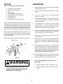
R
Fine Finish
T.M.
T.M.
STATI-KIT 2000
ELECTROSTATIC
SPRAYING SYSTEM
Model No. 0292003
R
HV
I
O
T0.2A
0
20
VM
HV
I
O
T0.2A
VM200
OWNER'S MANUAL
APPROVED
FOR ELECTROSTATIC FINISHING APPLICATION
POWER PACK , VM 200
P/N 0179637
POWER PACK , EPP 200
P/N 0179633
POWER PACK, EPP 2000
SPRAY GUN ,
SPRAY GUN ,
GM 2000 EAC
AIR HOSE
FLUID HOSE
GM 2000 EA
AIR HOSE
FLUID HOSE
P/N 0179673
P/N 0128510
P/N 9984482
P/N 0179221
P/N 0179248
P/N 0179966
1
CAUTION
Read Rules for
Safe Operation
and Instructions
Carefully
Form No.0292522-4/91A
CONTENTS
SAFETY PRECAUTIONS .................................................................... 3-6
SPECIFICATIONS................................................................................ 7
INTRODUCTIONS ............................................................................... 7
GENERAL DESCRIPTION .................................................................. 8
MOUNTING ARRANGEMENT ............................................................. 9
SET UP ................................................................................................ 9
OPERATION ........................................................................................ 10
CLEAN UP ........................................................................................... 11
TIP CHANGE ....................................................................................... 12
FILTER REPLACEMENT ..................................................................... 13
FRONT & REAR PACKING REPLACEMENT ..................................... 13
TROUBLE SHOOTING ........................................................................ 14-15
PARTS LIST ......................................................................................... 16-17
SPARE TIPS ........................................................................................ 18
WARRANTY ......................................................................................... 20
21
SAFETY PRECAUTIONS
This manual contains information which must be read and understood before using the equipment. When you come to an
area which has one of the following symbols, pay particular attention and make certain to heed the safeguard.
WARNING
Important safety information indicates a hazard which may cause serious injury or loss of life.
CAUTION
Important information that tells how to prevent damage to equipment or how to avoid causes of minor injuries.
Notes: Gives important information which should be given special attention.
31
WARNING
PREVENTION
HAZARD
Electrostatic arcing may cause an explosion or fire.
Solvent and paint fumes can explode or ignite causing
property damage and/or severe injury.
• Operator must be grounded. Grounding straps must be
used when wearing rubber soled shoes.
• Operator must be in contact with the spray gun handle;
cut out palm section of any work gloves to be used.
• Operator must remove all metal objects from his or her
person which are not grounded.
• The object being sprayed must be grounded.
• All metal objects within the spray area must be grounded
(including spray booth, part hangers, fire extinguishers,
etc.)
• Grounded conductive floor must be provided in spray
area.
• Turn off the Power Pack and unplug from outlet before
flushing out the gun, cleaning or replacing parts on the
gun such as changing tips.
• Exhaust and fresh air introduction must be provided to
keep the air within the spray area free of accumulation of
flammable vapors.
Explosion or fire. Solvent and paint fumes can explode or ignite causing property damage and/or severe injury.
• Smoking must not be allowed in spray area.
• Fire extinguishing equipment must be present and in
working order.
• Electrostatic arcing must be prevented. (See Electrostatic arcing)
• When flushing the system use only solvents recommended by the coatings manufacturer. Be sure Power
Pack is turned off and unplugged.
• Use only grounded high pressure fluid hose.
• Avoid all ignition sources such as static electrcity
sparks,open flames such as pilot lights, hot objects such
as cigarettes and sparks from connecting and disconnecting power cords and working light switches.
14
WARNING
PREVENTION
HAZARD
Toxic Substances: Some materials may be harmful if inhaled or come in contact with the skin.
• Follow the requirements of the Material Safety Data
Sheet supplied by the coatings manufacturer.
• Exhaust and fresh air introduction must be provided
within the spray area to keep the air free of accumulations of toxic materials.
• Wear a mask or respirator. Read all instructions for the
mask to insure that it will provide the necessary protection against the inhalation of harmful vapors.
Explosion hazard incompatible materials. May cause
property damage or severe injury.
• Some spray pumps prohibit the use of halogenated
hydrocarbon solvents.
• Halogenated hydrocarbon solvents such as methylene
chloride and 1,1,1 - Trichlorethane are not compatible
with aluminum and may cause an explosion. If you are
not sure of a material’s compatibility with aluminum,
contact your coatings supplier. Halogenated hydrocarbon solvents are compatible with the GM2000 spray gun
and may be used if the solvents are compatible with the
pump and other accessories.
Injection. A high pressure stream of paint can pierce the
skin and underling tissues, leading to serious injury and
possible amputation.
• Maximum operating range of the gun - 3625 PSI fluid
pressure.
• NEVER aim the gun at any part of the body under any
circumstances.
• NEVER let any part of the body come in contact with the
fluid stream. DO NOT come in contact with a fluid stream
created by a leak in the fluid hose.
• Paint hose can develop leaks from wear, kinking, abuse
etc. A leak is capable of injecting material into the skin.
Paint hose should be inspected before each use. Replace a damaged hose.
• NEVER put hand in front of the gun. Gloves will not
provide protection against an injection injury.
• ALWAYS lock the gun trigger when cleaning, changing
tips or leaving unattended.
• ALWAYS shut fluid pump off and release all pressure
before servicing, cleaning, or changing tips.
15
WARNING
PREVENTION
HAZARD
Injection (Con't)
• All accessories must be rated at or above the maximum
pressure rating of spray pump (includes spray tips, guns,
extensions and fluid hose.
• If you are injected, see a physician immediately.
DO NOT TREAT AS A SIMPLE CUT! It can lead
to amputation. See a physician immediately.
NOTE TO PHYSICIAN: Injection into the skin
is a traumatic injury. It is important to treat
the injury surgically as soon as possible. DO
NOT delay treatment to research toxicity.
Toxicity is a concern with some coatings
injected directly into the blood stream. Consultation with a plastic surgeon or reconstructive hand surgeon may be advisable.
• Read all instructions and safety precautions before operating.
General
• Comply with all appropriate local, state and national
codes governing ventilation, fire prevention, and operation of Electrostatic equipment usage.
• The United States Government Safety Standards have
been adopted under the Occupational Safety and Health
Act. These standards, particularly the General Standards, Part 1910 and the Construction Standard, Part
1926, should be consulted.
• NFPA Standard No. 33 is to be followed when setting up
your spray area. Contact the National Fire Protection
Association, Batterymarch Park, Quincy, Massachusetts,
02269 for more information.
• Check with insurance company for additional requirements.
• DO NOT substitute any other spray gun or power pack
with this system. Use only identical replacement parts.
61
SPECIFICATIONS
INTRODUCTION
GM2000 EAC SPRAYGUN (P/N 0179673)
Air Pressure, max.
Material Pressure, max.
Air Volume
Material Volume
Air Connector
Material Connector
Length
Height
Weight
Input voltage
Input Current, max.
Frequency
High Voltage
Output Current, max.
Polarity
Cable, Connecting
INTRODUCTION TO ELECTRO-STATIC
SPRAYING
145 psi
3625 psi
10 CFM@ 45 PSI
Varies due to Tip size
1/4 inch
NPS 1/4
11.8 inches
10 inches
21 oz.
22 VAC
0.8 A
26 kHz
80 kV DC
100 A AC
Negative
36 ft.
The spraying medium is atomized using a pneumatic or
diaphragm pump and a booster air feed supply. A high DC
voltage (up to 80 kV), applied across the grounded component and the electrode fitted to the gun body generates an
electric field and applies a negative charge to the paint
particles. These repel each other as they move from gun to
workpiece and so distribute evenly through the fine spray
cloud and then uniformly deposit on the positively grounded
surface. Particles shooting past the component remain
trapped in the electric field and deposit on the backside of
the work object. Effective material yield up to 90%, time
savings up to 80%, markedly improved quality of finish, less
cleaning and a healthier environment are the principal
properties of the process.
FEATURES:
VM200 ELECTROSTATIC POWER PACK
(P/N 0179637)
Length
Width
Height
Weight
Input - VAC
Power consumption max.
Output Voltage
Output Current max
Output Frequency
Power Cord
Minimum overspray
Coating by electrostatic wrap-around action
Good atomization of charged particles
7.5 inches
4.75 inches
3.5 inches
3.9 lbs.
110 - 60 Hz
15 W
80 KV
0.7 A
17 kHz
9 ft.
ADVANTAGES:
Effective material utilization up to 90%
Enormous time and labor savings
NOTE
Use only coating materials with a specific resistance of 50 - 3.500 K Ohms . If you are not
sure of the specific resistance check with the
coatings supplier before using.
7
1
GENERAL DESCRIPTION
VM 200 ELECTROSTATIC POWER PACK
GM2000 EAC SPRAY GUN
The heavy metal case is water tight. All external components and operating controls, as well as the case finish are
largely solvent-resistant.
The GM2000 EAC Electrostatic Air Coat Spraygun is
very light and easy to service. It can be used up to a
maximum operating pressure of 3625 PSI.
With the power switch on, the green pilot lamp lights up.
Internal components now convert the supplied voltage into
a pulsating DC voltage of 12 V and 17 kHz frequency. This
low output voltage supplies the GM 2000 EAC gun via the
connecting cable.
Trigger Lock: Turn knob clockwise to lock the trigger.
Electrostatic On/Off Switch: This switch can be used to turn
off the electrostatics. Sometimes the Faraday Cage effect
prevents proper coverage on inside corners. If you run into
this problem turn this switch off (up), spray the inside
corner(s), then turn the switch back on (down), and resume
electrostatic spraying.
When the gun trigger is pulled, a solenoid-operated Reed
contact initiates the switching on of the high voltage, signalled by lighting up of the red high voltage lamp. Via the
connecting cable to the gun, the 12 V/17 kHz, mediumfrequency, low voltage is now fed to the high-voltage
generating section inside the guard of the gun. Here, a
transformer within the cascade converts the low voltage into
a high voltage of 80 kV and applies this with negative
polarity to the electrodes.
Fluid Inlet: Securely fasten airless hose to this threaded
port. Be sure to use only hose with adequate pressure
rating.
Air Inlet: Securely fasten air hose to this threaded port.
RED HIGH VOLTAGE
LAMP
GREEN ON - OFF LAMP
Air Adjustment: This knob can be used to regulate the
amount of air that is used in spraying. Turn knob clockwise
until it closes, slowly turn knob counterclockwise until adequate air flow results.
HIGH VOLTAGE CABLE
SOCKET
HIGH VOLTAGE
ON - OFF SWITCH
AIR CONTROL KNOB
GM 2000
SPRAY GUN BODY
HV
I
TRIGGER LOCK
ELECTROSTATIC
TIP
O
ON/OFF SWITCH
HANDLE WITH HIGH VOLTAGE GENERATOR
PAINT FILTER
VM200
T0.2A
TRIGGER
GROUND CONNECTION
FUSE
Figure 2
Figure 1
18
TYPICAL MOUNTING
ARRANGEMENT
WAGNER AIRLESS SPRAYER
MOUNTING INSTRUCTIONS
1.
Use the allen wrench provided, attach the mounting
bracket (1) to the power pack (2) with the 2.4mm
lockwashers (3) and socket head screws (4).
2.
Place the power pack/mounting bracket assembly on
any 1" diameter tube, preferably as illustrated below.
3.
Align support clamps (5) with mounting bracket (1),
using the other allen wrench provided, attach the 2
pieces with the 4-1/4" lockwashers (6) and socket
head screws (7), tightening down equally on both
sides.
2
1
3
4
5
6
7
Figure 3
9
1
SET-UP
OPERATION
SET-UP VM 200 POWER PACK:
1.
2.
3.
4.
5.
6.
7.
8.
9.
GM 2000 EAC Socket Outlet
Ground Connection Knob
Fuse
On/Off Switch
On/Off Indicator Lamp (Green)
High Voltage Indicator Lamp (Red)
Grounding Cable
Ground Washer
GM 2000 EAC Connecting Cable
Step 1: Attach the grounding cable (7). Remove the ground
connection knob (2) and the ground washer (8). Put the ring
terminal end of the grounding cable on the grounding stud
and replace the ground washer (8) and the ground connection knob (2) securely. The end of the grounding cable with
the spring clip is to be attached to the object being sprayed.
Step 2: Attach the GM2000 EAC Connecting Cable (9) to
the Socket Outlet (1) on the Power Pack. Secure the cable
in place by screwing the nut onto the threads of the power
pack cable receptor.
Step 3: Plug power cord into a grounded 110 volt outlet.
1.
Set the VM 200 Power Pack Switch to the “I” position
(the green light turns on)
2.
Adjust the fluid pressure to achieve maximum atomization.
3.
If air assist is used, adjust air pressure regulator
between 10 & 30 psi.
4.
Be sure all items within the spray area are well grounded
— Refer back to Warnings — Electrostatic arcing may
cause fire/explosion.
5.
Test spray pattern and finish on a sample surface.
Keep the spray 8 - 12 inches away from the work
surface. Readjust fluid and/or air pressure to achieve
the optimum atomization and spray pattern.
6.
Use the Air Adjustment Knob (located at rear of the
spray gun) to control the volume of air. For additional
fine tuning rotate tip nut. (Round tip only).
7.
For best results, move the entire arm while spraying,
not just the wrist.
8.
When Power Pack is turned on and the trigger on the
spray gun is pulled, both the green light and the red
light will be lit. The red light indicates the high voltage
is on.
9.
The electrostatic On/Off Switch is to be turned off
when spraying into corners. With this switch in the “Off”
position, the red light on the Power Pack will not be lit.
(If the red light is lit with the electrostatic switch in the
“Off” position, DO NOT USE - TAKE TO AN AUTHORIZED SERVICE CENTER FOR REPAIR.)
POWER PACK
6
1
9
2
4
5
10. Lock the trigger on the spray gun after each use by
turning the trigger lock knob (located at the rear of the
spray gun) all the way to the right until it stops.
3
Figure 4
NOTE: The GM2000 EAC spray gun has a twostage trigger:
WARNING
1. Pulling the trigger part way - Only the air is on.
Power cord ground must remain intact. Do
not clip off ground pole on plug to fit a nongrounded socket. Static build up will result
which may cause an explosion.
2. Pulling the trigger all the way - Both air and fluid
are on.
10
1
CLEAN UP
CAUTION
WARNING
WHEN CLEANING THE ELECTROSTATIC
SYSTEM, THESE SAFETY PROCEDURES
MUST BE FOLLOWED. FAILURE TO FOLLOW THESE PROCEDURES MAY RESULT
IN AN EXPLOSION/FIRE.
• Clean equipment immediately after use.
• NEVER IMMERSE SPRAY GUN IN ANY FLUID
AT ANY TIME.
• Flush out fluid passages with a cleaning solvent compatible with the coating material being sprayed after each use.
• Turn power pack to the “OFF” position and unplug from
power source before starting to clean.
1.
Be sure the VM200 Power Pack is turned off and
unplugged from the power source.
2.
Check the coating manufacturer’s recommendation for a compatible cleaning solvent.
• Be certain that gun, cable, and power pack are free of all
paint spots and cleaning agent residue.
• Exhaust and fresh air introduction must be maintained
during the clean up operation.
NOTE
• Keep cleaning solvents in approved safety containers
and only in minimum quantities.
• The fluid passages of the spray gun should be
cleaned while cleaning the fluid hose and fluid
pump, following instructions, provided with
the fluid pump.
• All personnel and cleaning equipment, including container used in cleaning operation, must be grounded.
• Clean the spray tip and air cap by removing
from spray gun, rinsing in solvent, drying and
replacing on spray gun.
• DO NOT turn on the VM200 power pack until the
cleaning operation has been completed, all cleaning
materials have been removed from spray area, and
spray area is free of any vapors produced by the cleaning
operation.
• If defects in the equipment are found , DO NOT use until
repairs are completed.
1
11
ASSEMBLY OF FLAT SPRAY TIP
TIP CHANGE
If the round nozzle body is attached: Fig. 7.
CHANGING THE ROUND SPRAY TIP
(OPTIONAL):
1.
Screw out spray tip (B) with tip wrench (A). (See Fig.5)
2.
Attach desired spray tip and tighten with tip wrench.
• Remove tip body (D) from the spray gun body (F). Using
the procedure described in changing the round nozzle
body.
F
B
D
F
A
Figure 5
Figure 7
CHANGING THE ROUND NOZZLE BODY
H
• To remove the tip body (D) place the tip body removal
tool on the tip security lever (E) fig. 6A. Squeeze and
hold as shown in fig. 6B while unscrewing the tip body.
J
• Screw out spray tip (B) using the tip spanner and
remove diffuser ( C ) fig 6C.
G
Figure 8
• Carefully handle the carbide spray tip; avoid cleaning
with sharp-edged metal objects.
• Mount tip (G) on paint channel of spray gun body (F).
See Fig.8.
• Place air cap ( H ) on tip ( G ) fitting lugs of air cap into
grooves of tip insert.
• Mount air cap ( H) onto spray gun body until past the tip
security lever.
• Adjust desired air jet level by means of air cap horns
( J) and tighten air cap.
Tip removal tool
Figure 6B
E
Figure 6A
D
ALL PARTS NEEDED FOR THE FLAT TIP MUST BE
PURCHASED SEPARATELY. SEE PAGE 18 FOR PART
NUMBERS AND ORDERING INFORMATION.
C
Tip nut
B
Figure 6C
.
CLEANING OF THE FLAT SPRAY TIP
• Assemble in reverse order.
•
• Mount tip body ( D ) and tighten by hand. ( Do not use
tip removal tool ).
• Remove flat spray tip (G) and clean it.
Remove air cap (H). (See Fig. 8)
• Carefully handle the carbide flat spray tip (G); avoid
cleaning with sharp-edged metal objects.
• When adjusting tip nut leave a gap for atomizing air
between the air cap and tip body.
12
1
MAINTENANCE
VALVE SEAL REPLACEMENT
WARNING
To replace valve seals you must remove the entire valve
rod.
Turn off Power Pack and unplug from power source.
Relieve pressure to the Spray Gun, Lockout trigger and
turn off supply pump and air supply before cleaning or
replacing filters, tips, or any other parts failure to follw these
procedures may result in fire, explosion or injection injury.
FILTER REPLACEMENT AND CLEANING.
1.
Disconnect material hose at fitting (1) Fig 11. Hold
material connecting tube with the universal spanner
wrench at surface (A ).
2.
Disconnect union nut (4). Do not allow locking nut
(5) to rotate while disconnecting union nut.
3.
Unscrew red filter screw. Fig. 9
4.
Slip filter cylinder(6) from filter screw.
5.
Rinse or replace filter cylinder, (7).
6.
Assemble in reverse order.
7
1.
Actuate trigger (3) and unscrew trigger lock knob (2),
remove the compression spring. Fig. 11
2.
Remove screws holding trigger asembly in place and
remove trigger (3). Fig. 11
3.
Unscrew seal screw (11/C) from gun body. Fig. 12
4.
Carefully remove complete valve rod by pulling end of
rod (12). Fig. 12
5.
Hold the rod valve using the universal spanner at
surface (F) and using a pliers turn the valve seal
(8/B) and remove. Fig. 12
6.
Remove compression ring (9) and front seal
(10). Fig.12
7.
To remove push rod cap (14) hold universal spanner
at surface (E) and unscrew at surface (D). Fig.12
8.
Replace compression ring with O-Ring (9), front seal
(12), rear seal (11) and if necessary push rod seal
(15) and O-Ring (16) of the air valve . Fig. 12
9.
Assemble in reverse order.
6
Figure 9
A
2
FRONT PACKING ADJUSTMENT
1.
If there is evidence of material leakage past the front
seal (10) lightly tighten the packing nut (11)with the
universal wrench. Fig. 10
3
5
4
1
11
Figure 10
10
Figure 11
12
9
8
B
10
13
11
C
D
14
16
15
Figure 12
13
1
E
F
G
TROUBLESHOOTING
Problem
Cause
Solution
• Dead outlet.
• Live outlet.
• Fuse blown.
• Replace fuse.
• Not plugged in.
• Plug in.
• Faulty circuit board.
• Take to Authorized Service Center.
• Gun on-off switch performing
opposite.
• Defective switch.
• Take to Authorized Service Center.
• No red light on Power Pack.
• Cable from gun to Power Pack
loose or not connected.
• Tighten power cable.
• Cable from gun to Power Pack
defective.
• Replace power cable.
• Blown fuse.
• Check fuse; replace if necessary.
• If the trigger on the gun is pressed
and the above causes have been
checked and remedied and there is
still no high voltage, then the high
voltage generator or Power Pack
need service.
• Take to Authorized Service Center
• Plugged spray tip.
• Clean tip.
• Worn or faulty tip.
• Replace tip.
• Paint too thick.
• Thin paint.
• Uneven air distribution at tip nut.
• Clean all air passages.
• Object not grounded.
• Check ground.
• Cable not fitted properly.
• Check connection.
• Cable faulty.
• Replace cable.
• High voltage generator
• Replace.
• Power Pack is turned off.
• Turn on.
• Gun on/off switch is off.
• Turn on.
• Fluid pressure too high.
• Reduce fluid pressure.
• Air pressure too high.
• Reduce air pressure.
• Electrode dirty or damaged.
• Clean or replace.
• No green light on Power Pack
• Spray pattern not even;
unsymmetrical or poor atomization.
• Spray pattern is correct, but there is
no wraparound.
14
1
TROUBLESHOOTING
Problem
Cause
Solution
• Air leaking at tip without pulling
trigger.
• Air valve is faulty.
• Replace air valve.
• Air leaks between gun body and
gun barrel.
• Gun Barrel Nut.
• Tighten nut.
• No air at tip when trigger is pulled.
• Air hose not connected.
• Connect air hose
• No air supply
• Check air supply
• Wrong tip body fitted
• Fit correct EAC tip body
• Round tip nut screwed down too
hard.
• Unscrew nut slightly
• Air channels in tip body or cascade
blocked
• Unblock air channels as necessary
or take to authorized service center
• Material leaks at front or rear packings.
• Packings not tight enough.
.•
• Packing faulty.
• Replace packings as necessary.
• Material leaks at tip without pulling
trigger.
• Valve stem and valve seat dirty or
faulty.
• Clean or replace as necessary
• No material at tip when trigger is
pulled.
• Material leaks at joint between gun
body and gun barrel when trigger is
pulled.
Lightly tighten packing nuts.
• No material supply
• Check supply pressure
• Gun filter blocked or fitted upsidedown.
• Replace filter, or mount it correctly.
• Tip plugged.
• Unplug tip.
• Gun barrel nut loose
• Tighten nut. DO NOT overtighten.
• Material channel faulty
• Take to Authorized Service Center.
15
1
Figure 9
1
16
GM 2000 EAC
Item
1
2
3
4
5
6
7
8
9
10
11
12
13
14
15
16
17
18
19
20
21
22
23
24
25
26
27
28
30
31
32
33
34
35
36
37
38
39
40
41
44
45
46
47
48
49
50
51
52
53
54
55
Description
Part Number
Spray gun barrel
Bushing
Screw countersunk
Type plate
Screw flathead
O-ring
Knob, Air Adjustment
Trigger sleeve
Valve rod complete
Valve sealing element
O-ring
Compression ring
Seal
Sealing screw
Push-rod cap
Seal
Push-rod seal
O-ring
Valve push-rod
Valve rod
Valve rod spring guide
Compression spring
Adjusting element
Compression spring
Compressing element EAC
Locking nut
Double socket
Air hose
Connection adapter BSP 1/4
Connecting cable
Connecting adapter M16x1.5
Hose cover
Flat-head screw*
Trigger*
Cylindrical filter*
Filter screw
Material connector
High pressure hose
Protecting cap EAC
Nozzle EAC, flat
Compression spring
Tip insert EAC, flat
Nozzle EACR 2000
Tip insert EACR 15, standard
Air cap EACR
Tip body, EACR
Locking screw
Diffuser with sealing nipple
Wrench Universal
Glove
Tip Wrench
Tip body removal tool
0179500
0128336
0179354
9900962
9900810
9971003
0179416
0179396
0179254
0179236
9971182
0179343
0179341
0179342
0179340
0179395
0179339
9971372
0179337
0179335
0179394
9994247
0179253
9994248
0179488
0179356
9994627
0128510
9983226
Call Factory
0097201
0179248
9900808
0179219
9995611
0179383
0179241
9984482
0179482
0179678
9994269
See Nozzle List
0179679
0132724
0179536
0179664
0132351
0132516
0179901
9994682
0179902
0179963
171
Flat Tip
Part
Number
Tip
Orifice Size
Marking
(Inch)
0128550
0128216
0128552
0128217
0128201
0128554
0128218
0128212
0128556
0128219
0128213
0128215
0128565
0128559
0128561
0128562
0128563
9/15
9/20
11/15
11/20
11/50
13/15
13/20
13/50
15/15
15/20
15/50
18/50
21/20
21/50
26/50
31/50
36/50
.009
.009
.011
.011
.011
.013
.013
.013
.015
.015
.015
.018
.021
.021
.026
.031
.036
Round Tip
Fan
Width
Orifice
15°
20°
15°
20°
50°
15°
20°
50°
15°
20°
50°
50°
20°
50°
50°
50°
50°
Part
Number
0132720
0132721
0132722
0132723
0132724
0132725
0132726
0132727
0132728
0132729
0132730
0132731
Accessories
0088154
Fluid Pressure Gauge
1
18
Tip
Marking
Size
.001
(Inch)
Volume
oz./Min
R11/2
R12/2
R13/2
R14/2
R15/2
R16/2
R17/2
R18/2
R19/2
R20/2
R21/2
R22/2
.0066
.0080
.0092
.0104
.0110
.0115
.0121
.0126
.0132
.0139
.0145
.0151
2.28
3.07
3.74
4.77
5.29
6.02
6.72
7.30
8.32
9.22
9.92
10.75
@ 250 PSI
G.P.M.
.0178
.0240
.0292
.0373
.0413
.0470
.0525
.0570
.0650
.0720
.0775
.0840
19
LIMITED WARRANTY
ELECTROSTATIC PAINT SPRAY EQUIPMENT
To validate this warranty, the completed registration card must be mailed within one week of the date of purchase to Wagner Spray
Tech Corporation.
Wagner Spray Tech Corporation extends to the original purchaser of its electrostatic paint spray equipment a one year warranty
against defects in material or workmanship provided that the equipment is installed and operated in accordance with the
recommendations and instructions of Wagner Spray Tech Corporation. Wagner Spray Tech will repair or replace, at its option,
defective parts without charge if such parts are returned with transportation charges prepaid to the nearest authorized service
agency or to Wagner Spray Tech Corporation, 1770 Fernbrook Lane, Minneapolis, Minnesota.
This warranty does not cover:
1.
Equipment and accessories supplied to Wagner Spray Tech Corporation by other manufacturers including hose are covered
by the express warranties of the original manufacturers. Wagner Spray Tech Corporation will provide the purchaser with
reasonable information and assistance in making claims to the original manufacturers under their warranty.
2.
Normal wear and/or defects caused by or related to abrasion, corrosion, abuse, negligence, accident faulty installation or
tampering in a manner which impairs normal operation.
3.
Transportation costs and other incidental, direct, special or consequential damages or loss.
Any implied warranty of merchantability or fitness for a particular purpose on Wagner Spray Tech Corporation’s spray equipment
is limited in duration to the duration of this warranty.
Some states do not allow the exclusion of incidental or consequential damages, or allow limitations on how long an implied warranty
lasts, so the above limitations or exclusion may not apply to you. This warranty gives you specific legal rights, and you may also
have other rights which vary from state to state.
Copyright 1989 by Wagner Spray Tech Corporation
ALL RIGHTS RESERVED
U.S. PATENT 3,843,052
R
Wagner Spray Tech Corporation
1770 Fernbrook Lane
Minneapolis, Minnesota 55447
Telephone (612) 553-7000
PRINTED IN U.S.A.
20