1
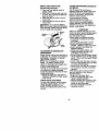
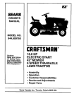
Owner's Manual
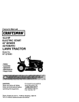
16.5 HP
ELECTRIC START
42" MOWER
6 SPEED TRANSAXLE
LAWN TRACTOR
EZ 3
Model No.
917.271133
•
•
•
•
Safety
Assembly
Operation
Maintenance
• Repair Parts
This product has a low emission engine which operates
differently from previously built engines. Before you start the englne, read end understand this Owner's Manual.
CAUTION:
Read and follow all Safety
Rules and Instructionsbefore
For answers to your questions
about this product, Call:
operating this equipment.
Sears Craftsman Help Line
5 am - 5 pm, Mort - Sat
1-800-659-5917
Sears, Roebuck and Co., Hoffman Estates, II 60179
Visit our Craftsmanwebsite:www.sears.com/craftsman
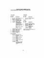
Warranty ...............................................
2
Safety Rules .........................................
3
Product Specifications .......................... 5
Assembly ..............................................
7
Operation ............................................
10
Maintenance Schedule ...................... 16
Service and Adjustments....................20
Storage ...............................................26
Troubleshooting.................................27
Repair Parts........................................32
Pads Ordedng ..................... Back Cover
LIMITED TWO YEAR WARRANTYON CRAFTSMAN RIDING EQUIPMENT PARTS
Fortwo (2) years from the date of purchase,if this CraftsmanRidingEquipmentis
maintained,lubricatedand tuned up accordingto the instructionsin the owner's
manual, Sears will repairor replace, free of charge, any parts found to be defectivein
matedal or workmanship.Warranty serviceis available free of chargeby takingyour
Craftsmanridingequipmentto yournearest Sears Service Center. In-homewarranty
service is available but a tripcharge will apply.This warrantyappliesonlywhile this
productis in the UnitedStates.
This Warranty does not cover:.
• Expendable items which become wom during normal use, such as blades, spark
plugs, air cleaners, belts and oil filters.
• Tire replacement or repair caused by punctures from outside objects, such as nails,
thorns, stumps, or glass.
• Rapairs necessary because of operator abuse, including but not limited to, damage
caused by towing objects beyond the capability of the dding equipment, impacting
objects that bend the frame or crankshaft, or over speeding the engine.
• Rapairs necessary because of operator negligence, including but not limited to,
electdcal and mechanical damage caused by improper storage, failure to use the
proper grade and amount of engine oil, failure to keep the deck clear of flammable
debds, or the failure to maintain the equipment according to the instructions contained in the owner's manual.
• Engine (fuel system) cleaning or repairs caused by fuel determined to be contami-"
hated or oxidized (stale). In general, fuel should be used within thirty (30) days of its
purchase date.
• Riding equipment used for commemial or rental purposes.
LIMITED 90 DAY WARRANTY ON BATTERY
For ninety(90) days from date of purchase,if any batteryincludedwith this riding
equipment provesdefective in materialor workmanshipand our testingdeterminesthe
batterywill not hold a charge, Sears willreplacethe batteryat no charge. Warranty
service is available free of charge by takingyourCraftsmanddingequipmentto your
nearest Sears Service Center. In-homewarrantyservice is availablebut a tdp charge
willapply.This warrantyapplies onlywhilethis productis in the United States.
TO LOCATE THE NEAREST SEARS SERVICE CENTER OR TO SCHEDULE
WARRANTY SERVICE, SIMPLY CONTACT SEARS AT 1-800-4-MY-HOME
IN-HOME
This Warranty gives you specific legal rights, and you may also have other dghts which
may vary from state to state.
Sears, Roebuckand Co., D/817 WA, HoffmanEstates, IL 60179
IMPORTANT: This cutting machine is capable of amputating hands and feet and
throwing objects. Failure to observe the following safety instructions could result in
serious injury or death.
I. GENERAL OPERATION
II. SLOPE OPERATION
• Read, understand, and follow all
Slopes are a major factor related to loss-ofinstructions in the manual and on the
control and tipover accidents, which can
machine before starting.
result in severe injury or death. All slopes
• Only allow responsible adults, who are
require extra caution. If you cannot back up
familiar with the instructions, to operate
the slope or if you feel uneasy on it, do not
the machine.
mow it.
• Clear the area of objects such as
DO:
rocks, toys, wire, etc., which could be
• Mow up and down slopes, not across.
picked up and thrown by the blade.
• Remove obstacles such as rocks, tree
• Be sure the area is clear of other
limbs, etc.
people before mowing. Stop machine
• Watch for holes, ruts, or bumps.
if anyone enters the area.
Uneven terrain could overturn the
• Never carry passengers.
machine. Tall grass can hide obstacles.
• Do not mow in reverse unless abso• Use slow speed. Choose a low gear
lutely necessary. Always look down
so that you will not have to stop or shift
and behind before and while backing.
while on the slope.
• Be aware of the mower discharge
• Follow the manufacturer's recommendirection and do not point it at anyone.
dations for wheel weights or counterDo not operate the mower without
weights to improve stability.
either the entire grass catcher or the
• Use extra care with grass catchers or
guard in place.
other attachments. These can change
• Slow down before turning.
the stability of the machine.
• Never leave a running machine
• Keep all movement on the slopes slow
unattended. Always turn off blades, set
and gradual. Do not make sudden
parking brake, stop engine, and
changes in speed or direction.
remove keys before dismounting.
• Avoid starting or stopping on a slope. If
• Turn off blades when not mowing.
tires lose traction, disengage the
• Stop engine before removing grass
blades and proceed slowly straight
catcher or unclogging chute.
down the slope.
• Mow only in daylight or good artificial
DO NOT:
light.
• Do not turn on slopes unless neces• Do not operate the machine while
sary, and then, turn slowly and graduunder the influence of alcohol or drugs.
ally downhill, if possible.
• Watch for traffic when operating near or
• Do not mow near drop-offs, ditches, or
crossing roadways.
embankments. The mower could
• Use extra care when loading or
suddenly turn over if a wheel is over
unloading the machine into a trailer or
the edge of a cliff or ditch, or if an edge
truck.
caves in.
• Data indicates that operators, age 60
• Do not mow on wet grass. Reduced
years and above, are involved in a
traction could cause sliding.
large percentage of riding mower•
Do not try to stabilize the machine by
related injuries. These operators
putting your foot on the ground.
should evaluate their ability to operate
• Do not use grass catcher on steep
the riding mower safely enough to
slopes.
protect themselves and others from
serious injury.
3
III.
CHILDREN
Tragicaccidentscan occur if the operator
is not alert to the presenceof children.
Childrenare often attractedto the
machine and the mowing activity. Never
assume that childrenwill remainwhere
you lastsaw them.
• Keep childrenout of the mowingarea
and under the watchfulcare of another
responsibleadult.
• 8e alert and turn machineoff if children
enter the area.
• Before and when backing,look behind
and downfor small children.
• Never carry children. They may fall off
and be sadously injured or interfere
with safe machine operation,
• Never allowchildrento operate the
machine.
• Use extra care when approachingblind
comers,shrubs,trees, or otherobjects
that may obscurevision.
IV. SERVICE
• Use extra care in handlinggasoline
and otherfuels. They are flammable
and vapors are explosive.
-Use only an approvedcontainer.
- Never remove gas cap or add fuel
with the engine running. Allow
engine to cool before refueling.Do
notsmoke.
* Never refuelthe machine indoors.
oNever store the machineor fuel
containerinside where there is an
open flame, such as a water heater.
• Be sure the area is clear of other
people before mowing.Stop machineif
anyoneenters the area.
• Never camJpassengemor children
even withthe blades off.
• Do not mow in reverse unleSSabsolutelynecessary.Always look down
and behindbefore and while backing.
• Never carry children.They may fall off
and be seriouslyinjuredor interfere
with safe machine operation.
• Keep childrenout of the mowing area
and under the watchful care of another
responsible adult.
• Never run a machine inside a closed
area.
• Keep nuts and bolts, especially blade
attachment bolts, tight and keep
equipment in good condition.
• Never tamper with safety devices.
Check their proper operation regularly.
• Keep machine free of grass, leaves, or
other debris build-up. Clean oil or fuel
spillage. Allow machine to cool before
storing.
• Stop and inspect the equipment if you
strike an object, Repair, if necessary,
before restarting.
• Never make adjustments or repairs
with the engine running.
• Grass catcher components are subject
to wear, damage, and deterioration,
which coutd expose moving parts or
allow objects to be thrown. Frequently
check components and replace with
manufacturer's recommended pads,
when necessary.
• Mower blades are sharp and can cut.
Wrap the blade(s) or wear gloves, and
use extra caution when servicing them.
• Check brake operation frequently.
Adjust and service as required.
• Be alert and turn machine off if childre
enter the area.
• Before and when backing, look behin(
and down for small children.
• Mow up and down slopes (15 ° Max),
not across.
• Remove obstacles such as rocks, tree
limbs, etc.
• Watch for holes, ruts, or humps.
Uneven terrain could overturn the
machine. Tall grass can hide obstacle.'
• Use slow speed. Choose a low gear so
that you willnot have to stop or shift
white on the slope.
• Avoid startingor stoppingon a slope. If
tires lose traction,disengagethe
blades and proceed slowlystraight
downthe slope.
• If machinestopswhile going uphill,
disengageblades, shift into reverse
and back down slowly.
• Do not turnon slopes unlessnecessary, and then, turn slowlyand gradually downhill,if possible.
_bLook for this symbolto pointout
importantsafety precautions.It means
CAUTION!!! BECOMEALERT!!! YOUR
SAFETY IS INVOLVED.
_,L CAUTION: Tow only the attachments
that are recommended by and comply
with specifications of the manufacturer of
your tractor. Use common sense when
towing. Operate only at the lowest
possible speed when on a slope. Too
heavy of a load, while on a slope, is
dangerous. Tires can lose traction with
the ground and cause you to lose control
of your tractor.
,_WARNING:
Engine exhaust, some of
its constituents, and certain vehicle
components contain or emit chemicals
known to the State of California to cause
cancer and birth defects or other reproductive harm.
,_WARNING:
Battery posts, terminals
and related accessories contain lead and
lead compounds, chemicals known to the
State of California to cause cancer and
birth defects or other reproductive harm.
Wash hands after handling,
,_& CAUTION: In order to prevent
accidentalstartingwhen setting up,
transporting,adjustingor making repairs,
always disconnectspark plug wire and
place wire where it cannotcontact spark
plug.
_, CAUTION: Do not coastdown a hill
in neutral, you may lose controlof the
tractor.
5
PRODUCT SPECIRCATIONS
GASOLINE
CAPACITY
_NDTYPE:
1.25 GALLONS
UNLEADED
REGULAR
OILTYPE
SAE 10W30 (ABOVE
32°F)
SAE 5W-30
(BELOW 32°F)
W/FILTER: 4.0 PINTS
W/OFILTER: 3.5 PINTS
API-SF-SJ):
)IL CAPACITY:
Shouldyou experienceany problem you
cannoteasily remedy,please contacta
Sears or otherqualifiedservice center.
We have competent,well-trainedtechnicians and the propertoolsto serviceor
repairthis tractor.
Please read and retainthis manual. The
instructionswill enable you to assemble
and maintainyourtractorproperly.
Always observethe "SAFETY RULES".
;PARK PLUG:
CHAMPION RC12YC
GAP: .030")
3ROUND SPEED FORWARD:
REPAIR AGREEMENT
A Repair Agreement is available on this
product. Cc_qtact
yournearest Seats
store for details.
MPH):
CUSTOMER RESPONSIBILITIES
tIRE PRESSURE:
3HARGING
3YSTEM:
1sT
2 N°
3 _°
4TM
5TM
6 TM
1.2
1.5
2.4
3.5
4.8
5.3
• Read and observe the safety rules.
• Follow a regular schedule in maintaining, caring for and using your tractor.
• Follow the instructions under "Maintenance" and =Storege" sections of this
owner's manual.
REVERSE: 1.5
FRONT: 14 PSI
REAR: 10 PSI
WARNING: This tractor is equipped
with an intemal combustion engine and
should not be used on or near any
unimproved forest-covered, brush.
covered or grass-covered land unless th
engine's exhaust system is equipped wil
15AMPS @ 3600 RPM
3ATTE RY:
AMP/HR:
30
MIN. CCA: 240
CASE SJZE: Uf R
3LADE BOLT
rORQUE:
27-35 FT. LBS.
a spark arrester meeting applicable Ioc_
or state laws (if any). If a spark arrester i,
used, it should be maintained in effectiw
working order by the operator,
In the state of California the above is
required by law (Section 4442 of the
California Public Resources Code).
Other states may have similar laws.
Federal laws apply on federal lands, A
spark arrester for the muffler is available
through your nearest Sears service
center (See REPAIR PARTS section of
this manual).
CONGRATULATIONS on yourpurchase
of a new tractor. It has been designed,
engineered and manufactured to give
you the best possibledependabilityand
performance.
6
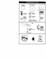
Steering Wheel
Steering
Wheel Insert
(1) Large FlatWasher
(1) Hex Bolt
washer
(1) Lock 3/8
3/8-16 x 1
(1) Locknut
5/16-18
Steering
Boot _/"
_
(1) Hex Bolt
5/16-18 x 1-1/4
Steedng
Extension
Shaft
Steering
Wheel
Adapter
Seat
(_Washer
17/32 x 1-3/16 x 12
Gauge
_(1)
(_) Shoulder
olt 5/16-18
Knob
Keys
Slope Sheet
(2) Keys
Video Cassette
Yournewtractor
hasbeen assembledat the factory with exceptionof those parts left
unassembledfor shippingpurposes. To ensure safe and properoperationof your
tractorall parts and hardwareyou assemble mustbe tightenedsecurelY. Use the
correcttools as necessaryto insurepropertightness.
TOOLS
REQUIRED
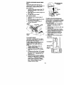
6. Assemblelarge flat washer,3/8 lock
washer, 3/8 hex boltand tighten
securely.
7. Snap steeringwheel insertintocenter
of steering wheel.
8. Remove protectivematerialsfrom
tractor hood and grill
IMPORTANT: Check for and removeany
staples in skid that may puncturetires
where tractoris to rolloff skid.
FOR ASSEMBLY
A socket wrench set will make assembly
easier. Standard wrench sizes are listed.
(1) 9/16"wrench
(1) Pliers
(21 1/2" wrench
(1) Utility knife
(1) 3/4" socket with
(1) Tire pressure
drive ratchet
gauge
When right or left hand is mentioned in
this manual, it means when you are in
the operating position (seated behind
the steedng wheel).
TO REMOVETRACTOR
FROM
CARTON
UNPACK CARTON
1. Remove all accessible loose parts
and pads cartons from carton.
2. Cut, from top to bottom, along lines
on all four comers of carton, and lay
panels flat.
3. Remove mower and packing matedals.
4. Check for any additional loose parts
or cartons and remove.
_81
n:::Bol t
/_
LLaC_We
a;h_ r
- Wsshe
SteedngWheel
Tabs
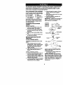
BEFORE REMOVINGTRACTOR
FROM SKID
ATTACH STEERING WHEEL
Extension
Shaft
Adapter_
ASSEMBLE EXTENSION SHAFT AND
SOOT
1. Slide extensionshaft onto lower
steedngshaft. Alignmountingholes
in extensionand lowershafts and
install5/16 he)( bolt and Iocknut.
Tighten securely.
2. Place tabs of steering bootover tab
slots in dash and pushdown to
secure.
INSTALLSTEERING WHEEL
3. Positionfrontwheels of the tractorso
they are pointingstraightforward.
4. Remove steering wheel adapterfrom
steering wheel and slide adapter onto
steedngshaft extension.
5. Positionsteeringwheel so cross bars
are horizontal(left to dght)and slide
insideboot and ontoadapter.
5/16 Hex Bolt
-i
Lower
Steering
Shaft
'
,.
_ "-.
""
",
"
_
- ,. _
Tab
Slots
HOWTO SET UPYOURTRACTOR
CHECK BATTERY
1. Lift seat pan to raised position and
open battery box door.
NOTE: If this battery is put into service
after month and year indicated on label
(label located between terminals) charge
battery for minimum of one hour at 6-10
amps. (See "BATTERY" in Maintenance
section of this manual for charging
instructions).
8
Label
Battery
Door
INSTALL SEAT
Adjustseat beforetighteningadjustment
knob.
1. Remove adjustmentknob and flat
washer securingseat to cardboard
packingand set aside for assemblyof
seat to tractor.
2. Pivot seat upward and removefrom
the cardboardpacking.Remove the
cardboard packing and discard.
3. Place seat on seat pan and assemble
shoulder bolt. Tightenshoulder bolt
securely,
4. Assembleadjustmentknob and flat
washer loosely. Do not tighten.
5. Lower seat into operatingpositionand
sit on seat.
6. Slide seat until a comfortableposition
is reached whichallowsyou to press
clutch/brakepedal all the way down.
7. Get offseat withoutmovingits
adjusted position.
8. Raise seat and tighten adjustment
knob securely.
Seat
Shoulder Seat Pan
Bolt
Fiat Washer
Adjustment
Knob
TO ROLLTRACTOR
OFF SKID (See
OperaUon section for location and
function of controls)
1. Press lift lever plunger and raise
attachment lift lever to its highest
position.
2. Release parking brake by depressing
clutch/brake pedal.
3. Place gearshift lever in neutral (N)
position.
4. Roll tractor forward off skid,
5. Remove banding holding discharge
guard up against tractor.
TO DRIVETRACTOR
OFF SKID (See
Operation section for location and
function
of controls)
_I=WARNING: Before starting, read,
understand and fo_ow all insfructio_nsin
the Operation section of this manual. Be
sure tractor is in a well-ventilated area. Be
sure the area in front of tractor is clear of
other people and objects.
1. Be sure all the above assembly steps
have been completed.
2. Check engine oil level and fill fuel
tank with gasoline.
3. Sit on seat in operating position,
depress clutch/brake pedal and set
the parking brake.
4. Place gear shift lever in neutral (N)
position.
5. Press lift lever plunger and raise
attachment lift lever to its highest
position.
6. Start the engine. After engine has
started, move throttle control to idle
position.
7. Depress clutch/brake pedal into full
"BRAKE" position and hold. Move
gearshift lever to 1st gear.
8. Slowly release clutch/brake pedal and
slowly drive tractor off skid.
9. Apply brake to stop tractor, set parking
brake and place gearshift lever in
neutral position.
10.Tum ignition key to "OFF" position.
Continue with the instructions that follow.
NOTE: You maynow roll or drive your
tractoroff the skid.Followthe appropriate
instructionbelow to remove the tractor
from the skid,
J
9
INSTALL MULCHER PLATE
(If previously removed)
1. Raise and hold deflectorshield in
uprightposition.
2. Place frontof mulcher plate over front
of mower deck openingand slide into
place, as shown.
3. Hookfrontlatch intohole on frontof
mower deck.
4. Hook rear latch into holeon back of
mower deck.
_I_CAUTION: Do not removedeflector
shieldfrom mower.Raise and hold shield
when attachingmulcher plate and allow it
to rest on plate while in operation.
CHECK FOR PROPER POSITION OF
ALL BELTS
See the figuresthat are shownfor
replacingmotion and mower blade drive
belts in the Service and Adjustments
sectionof this manual. Verifythat the
belts are routed correctly.
CHECK BRAKE SYSTEM
After you learn howto operateyour
tractor,checkto see that the brake is
propedyadjusted. See "TO ADJUST
BRAKE"in the Serviceand Adjustments
sectionof this manual.
,/'CHECKLIST
Before
you
operate
and enjoy your new
Mulcher
tractor, we wish to assure that you receive
Plate
the best performance and satisfaction
Shield
from this Quality Product.
Please review the following checklist:
v'AII assembly instructions have been
completed.
,/No remaining loose parts in carton.
v"Battery is properly prepared and
Latch
charged. (Minimum 1 hour at 6 amps).
Hooks
v" Seat is adjusted comfortably and
tightened securely.
,/'All tires are properly inflated. (For
TO CONVERTTO BAGGING OR
shipping purposes, the tires were
DISCHARGING
ovednflated at the factory).
Simplyremove mulcherplate and store in ./Be sure mower deck is propedy leveled
a safe place.Yourmower is now ready for
side-to-side/front-to-rear for best cutting
dischargingor installationof optional
results. (Tires must be propedy inflated
grass catcheraccessory.
for leveling).
NOTE: It is not necessaryto change
v'Check mower and drive belts. Be sure
blades. The mulcherbladesare dethey are routed properly around pulleys.
and inside all belt keepers.
signed for dischargingand baggingalso,
,/'Check wiring. See that all connections
CHECKTIRE PRESSURE
are still secure and wires are properly
The tires on your tractorwere ovednflated
clamped.
at the factory for shippingpurposes.
While learning how to use your tractor,
Correct tire pressureis importantfor best
pay extra attention to the following
cuttingperformance.
important items:
• Reducetire pressureto PSI shownin
V"
Engine oil is at proper level.
=PRODUCTSPECIFICATIONS"section
v" Fuel tank is filled with fresh, clean.
of this manual.
regular unleaded gasoline.
CHECK DECK LEVELNESS
v"Become familiar with all controls - their
location and function. Operate them
For bestcuttingresults,mower housing
before you start the engine.
shouldbe propedyleveled. See "TO
,/Be sure brake system is in safe
LEVEL MOWER HOUSING"in the
operating condition.
Service and Adjustmentssectionof this
manual.
10
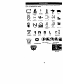
These symbolsmay appear on your tractoror in literaturesuppliedwith the product.
Learn and understandtheir meaning.
BATTERY
CAUTION OR
WARNING
REVERSE
FORWARD
FAST
SLOW
ENGINE ON
ENGINE OFF
OIL PRESSURE
LIGHTS ON
OVER TEMP
LIGHT
FUEL
CHOKE
MOWER HEtGHT
PARKING BRAKE
LOCKED
UNLOCKED
L
MOWER LIFT
r_'_ R N H L
ATTACHMENT
CLUTCH ENGAGED
REVERSE
NEUTRAL
HIGH
LOW
KEEP AREA CLEAR
IGNITION
ATTACHMENT
CLUTCH DISENGAGED
PARKING BRAKE
SLOPE HAZARDS
(SEE SAFETY RULES SECTION)
FREE WHEEL
(AutOmatic Models only)
DANGER, KEEP HANDS AND FEET AWAY
11
KNOWYOURTRACTOR
READ THIS OWNER'S MANUAL AND SAFETY RULES BEFORE OPERATING
YOUR TRACTOR
Compare the illustrations with your tractor to familiarize yourself with the locations of
various controls and adjustments. Save this manual for future reference.
Attachment
Clutch Lever
Ignition Switch
Light Switch
Lift
Amme_r
Plunger
Throttle/Choke
Control
':
Attachment
U_ Lever
Clutch/
Brake
Pedal
Parking Brake
Lever
Heigt
Adjustment
Knob
Gearshift Lever
Our tractors conform to the safety standards of the American
National Standards Institute.
AMMETER - Indicatescharging(+) or
discharging(-) of battery.
ATTACHMENT CLUTCH LEVER - Used
to engage the mower blades, or other
attachmentsmountedto yourtractor.
ATTACHMENT LIFT LEVER - Used to
raise, lower,and adjustthe mower deck
or otherattachmentsmountedto your
tractor.
CLUTCH/BRAKE PEDAL - Used for
doclutchingand brakingthe tractorand
startingthe engine.
GEARSHIFT LEVER - Selectsthe speed
and directionof tractor.
IGNITION SWITCH - Used for starting and
stopping the engine,
LIFT LEVER PLUNGER - Used to release
attachment lift lever when changing its
position,
LIGHT SWITCH - Turns the headlights on
and off,
PARKING BRAKE LEVER - Locks clutch/
brake pedal into the brake position.
THROTTLE/CHOKE
CONTROL - Used
for starting and controlling engine speed.
HEIGHT ADJUSTMENT KNOB - Used to
adjust the mower cutting height.
12
The operation of any tractor can result in foreign objects thrown into the
eyes, which can result in severe eye damage. Always wear safety
glasses or eye shields while operating your tractor or performing any
adjustments or repairs. We recommend a wide vision safety mask over
spectacles or standard safety glasses.
HOWTO USEYOURTRACTOR
TO SET PARKING BRAKE
Your tractor is equipped with an operator
presence sensing switch. When engine
is running, any attempt by the operator to
leave the seat without first setting the
parking brake will shut off the engine,
1. Depress clutch/brake pedal into full
"BRAKE" position and hold.
2. Place parking brake lever in "ENGAGED" position and release
pressure from clutch/brake pedal,
Pedal should remain in "BRAKE"
position. Make sure parking brake will
hold tractor secure.
IMPORTANT: Leaving the ignition switch
in any position other than "OFF = will
cause the battery to be discharged,
(dead).
NOTE: Under certain conditions when
tractor is standing idle with the engine
running, hot engine exhaust gases may
cause "browning" of grass. To eliminate
this possibility, always stop engine when
stopping tractor on grass areas.
p_eCAUTION: Always stop tractor comtely, as described above, before
leaving the operator's position; to empty
grass catcher, etc.
TO USE THROTTLE CONTROL
Always operate engine at full throttle.
• Operating engine at less than full
throttle reduces the battery charging
rate.
• Full throttle offers the best bagging and
mower performance.
TO MOVE FORWARD AND
BACKWARD
A_achmentClutch
Lever "Engaged"
;_/gnition
Position
/ :o,oongo0ed
Thro_
Control
Clutch/_',_
Brake,,
\ ,-"_"_"
.\'\ \V\
Key
P,_a.rking
Broke
_Engaged"
r-_',
"Disengaged' Height
Position
AdjustmentKnob
The direction and speed of movement is
controlled by the gearshift lever.
1. Start tractor with clutch/brake pedal
depressed and gearshift lever in
neutral (N) position.
2. Move gearshift lever to desired
position.
3. Slowly release clutch/brake pedal to
start movement.
IMPORTANT: Bring tractor to a complete
stop before shifting or changing gears.
Failure to do so will shorten the useful life
of your transaxle.
TO ADJUST MOWER CUI"I'ING HEIGHT
Gearshift
Lever
STOPPING
MOWER BLADES • To stop mower blades,move attachment clutch lever to =DISENGAGED"
position,
GROUND DRIVE • To stop ground drive, depress clutch/
brake pedal into full "BRAKE" position.
• Move gearshift lever to neutral (N)
position.
ENGINE• Move throttle control to slow position.
NOTE: Failure to move throttle control to
slow position end allowing engine to idle
before stopping may cause engine to
backfire".
• Turn ignition key to "OFP' position and
remove key. Always remove key when
leaving tractor to prevent unauthorized
use.
• Never use choke to stop engine.
The cutting height is controlled by tuming
the height adjustment knob in desired
direction.
•Tum knob clockwise ( F_ ) to raise
cutting height.
•Tum
knob counterclockwise (1_'_) to
lower cutting height.
The cutting height range is approximately
1-1/2" to 4". The heights are measured
from the ground to the blade tip with the
engine not running. These heights are
approximate and may vary depending
upon soil conditions, height of grass and
types of grass being mowed.
13
• The average lawn should be cut to
approximately 2-1/2 inches during the
cool season and to over 3 inches
during hot months. For healthier and
better looking lawns, mow often and
after moderate growth.
• For best cutting performance, grass
over 6 inches in height should be
mowed twice. Make the first cut
relatively high; the second to desired
height.
TO ADJUST GAUGE WHEELS
Gauge wheels are properly adjusted
when they are slightly off the ground
when mower is at the desired cutting
height in operating position. Gauge
wheels then keep the deck in proper
position to help prevent scalping in most
terrain conditions.
NOTE: Adjust gauge wheels with tractor
on a fiat level surface.
1. Adjust mower to desired cutting height
(See "TO ADJUST MOWER CUTTING
HEIGHT" in the Operation section of
this manual).
2. With mower in desired height of cut
position, gauge wheels should be
assembled so they are slightly off the
ground. Install gauge wheel in
appropdate hole with shoulder bolt, 3/
8 washer, and 3/8-16 Iocknut and
tighten securely,
3. Repeat for opposite side installing
gauge wheel in same adjustment
hole.
Gauge
Wheel
-_
/2_1,,.._-_"
_
Mounting ¢
Brscket "_
L_l_ut
3/8-16 .._.._...__
.
3/8 Washer _,
Gauge Wheel f
_-
_
,_.ShoulderBolt
-- _
TO OPERATE MOWER
Your tractor is equipped with an operator
presence sensing switch. Any attempt by
the operator to leave the seat with the
engine running and the attachment clutch
engaged will shut off the engine.
1. Select desired height of cut.
2. Lower mower with attachment lift
control.
3. Start mower blades by engaging
attachment clutch control.
TO STOP MOWER BLADES disengage attachment clutch control.
CAUTION: Do not operate the mower
without either the entire grass catcher, on
mowers so equipped, or the discharge
guard in place.
Attachment
Clutch Lever ._
Attachemnt
,Engaged__/)
,1/Lift
Lever High
Position
_i,_
_¢_
_-_:". j_
"Disengaged" _
Position
_
Position
_'/_b_//_
TO OPERATE ON HILLS
CAUTION: Do not driveup or down hills
with slopesgreaterthan 15° and do not
drive acrossany slope.
• Choose the slowestspeed before
startingup or down hills.
• Avoidstoppingor changingspeed on
hills.
• If slowingis necessary,move throttle
controlleverto slowerposition.
• If stoppingis absolutelynecessary,
push clutch/brakepedal quicklyto
brake position and engage parking
brake.
• Move gearshift lever to 1st gear. Be
sure you have allowed roomfor tractor
to rollslightlyas you restartmovement.
• To restartmovement,slowlyrelease
parkingbrake and clutch/brakepedal.
• Make all turnsslowly.
TO TRANSPORT
• Raise attachment lift to highest position
with attachment lift control.
• When pushing or towing your tractor,
be sure gearshift lever is in neutral (N)
position.
• Do not push or tow tractor at more than
five (5) MPH.
NOTE: To protect hood from damage
when transporting your tractor on a truck
or a trailer, be sure hood is closed and
secured to tractor. Use an appropriate
means of tying hood to tractor (rope, cord,
etc.).
14
TOWING CARTS AND OTHER
ATTACHMENTS
Tow only the attachments that are
recommended by and comply with
specifications of the manufacturer of your
tractor. Use common sense when towing.
Too heavy of a load, while on a slope, is
dangerous. Tires can lose traction with the
ground end cause you to lose control of
your tractor.
BEFORE STARTINGTHE
ENGINE
CHECK ENGINE OIL LEVEL
The engine in your tractor has been
shipped, from the factory, already filled
with summer weight oil.
1. Check engine oil with tractor on level
ground.
2. Unthread and remove oil fill cap/
dipstick; wipe oil off. Reinsert the
dipstick into the tube and rest oil fill
cap on the tube. Do not thread the
cap onto the tube. Remove and read
oil level. If necessary, add oil until
=FULL" mark on dipstick is reached.
Do not overfiU.
• For cold weather operation you should
change oil for easier starting (See "OIL
VISCOSITY CHART" in the Maintenance section of this manual).
• To change engine oil, see the Maintenance section in this manual.
ADD GASOLINE
• Fill fuel tank. Use fresh, clean, regular
unleaded gasoline with a minimum of
87 octane. (Use of leaded gasoline
will increase carbon and lead oxide
deposits and reduce valve life). Do not
mix oil with gasoline. Purchase fuel in
quantities that can be used within 30
days to assure fuel freshness.
IMPORTANT: When operating in
temperatures below32°F(0°C), use fresh,
clean winter grade gasoline to help
insure good cold weather starting.
_)&WARNING: Experience indicates that
alcohol blended fuels (called gasohol or
using ethanol or methanol) can attract
moisture which leads to separation and
formation of acids during storage. Acidic
gas can damage the fuel system of an
engine while in storage. To avoid engine
problems, the fuel system should be
emptied before storage of 30 days or
longer. Drain the gas tank, start the
engine and let it run until the fuel lines
and carburetor are empty.
Use fresh fuel next season. See Storage
Instructions for additional information.
Never use engine or carburetor cleaner
products in the fuel tank or permanent
damage may occur.
_I=CAUTION: Fill to bottom of gas tank
filler neck. Do not overfill. Wipe off any
spilled oil or fuel. Do not store, spill or
use gasoline near an open flame.
TO START ENGINE
When starling the engine for the firsttime or if
the engine has mn out of fuel, itwUltake extta
crankingtime to move fuel from the tank to
the engine.
1. Sit on seat in operating position,
depress clutch/brake pedal and set
parking brake.
2. Place gear shift lever in neutral (N)
position.
3. Move attachment clutch to "DISENGAGED" position.
4. Move throttle control to choke position.
NOTE: Before starting,read the warm and
cold starting procedures below.
5. Insert key into ignition and tum key
clockwise to =START" position and
release key as soon as engine starts.
Do not run starter continuously for
more than fifteen seconds per minute.
If the engine does not start after
several attempts, move throttle control
to fast position, wait a few minutes and
try again. If engine still does not start,
move the throttle control back to the
choke position and retry.
WARM WEATHER STARTING (50° F and
above)
6. When engine starts, move the throttle
control to the fast position.
• The attachments and ground drive can
now be used. If the engine does not
accept the load, restart the engine and
allow it to warm up for one minute
using the choke as described above.
COLD WEATHER STARTING ( 50° F and
below)
6. When engine starts, allow engine to
run with the throttle control in the
choke position until the engine runs
roughly, then move throttle control to
fast position. This may require an
engine warm-up period from several
seconds to several minutes, depending on the temperature.
15
• The attachments can also be used
during the engine warm-up period.
NOTE: tfat a highaltitude(above 3000 feet)
or in cold temperatures (below32 F) the
carburetorfuel mixture may need to be
adjusted for best sngine performance. See
"TO ADJUST CARBURETOR" in the SeMce
and Adjustmentssection of this manual.
MOWING TIPS
• Tire chains cannot be used when the
mower housing is attached to tractor.
• Mower should be properly leveled for
best mowing performance. See "TO
LEVEL MOWER HOUSING" in the
Service and Adjustments section of this
manual.
• The left hand side of mower should be
used for trimming.
• Drive so that clippings are discharged
onto the area that has been cut. Have
the cut area to the right of the tractor.
This will result in a more even distribution of clippings and more uniform
cutting.
• When mowing large areas, start by
tuming to the right so that clippings will
discharge away from shrubs, fences,
driveways, etc. After one or two
rounds, mow in the opposite direction
making left hand turns until finished.
• If grass is extremely tall, it should be
mowed twice to reduce load and
possible fire hazard from dried clippings. Make first cut relatively high; the
second to the desired height.
• Do not mow grass when it is wet. Wet
grass will plug mower and leave
undesirable clumps. Allow grass to dry
before mowing.
• Always operate engine at full throttle
when mowing to assure better mowing
performance and proper discharge of
material. Regulate ground speed by
selecting a low enough gear to give the
mower cutting performance as well as
the quality of cut desired.
• When operating attachments, select a
ground speed that will suit the terrain
and give best performance of the
attachment being used.
f
MULCHING MOWING TIPS
IMPORTANT: For best performance,
keep mower housing free of built-up
grass and trash. Clean after each use.
• The special mulching blade will recut
the grass clippings many times and
reduce them in size so that as they fall
onto the lawn they will disperse into the
grass and not be noticed. Also, the
mulched grass will biodegrade quickly
to provide nutrients for the lawn.
Always mulch with your highest engine
(blade) speed as this will provide the
best recutting action of the blades.
• Avoid cutting your lawn when it is wet.
Wet grass tends to form clumps and
interferes with the mulching action.
The best time to mow your lawn is the
early afternoon. At this time the grass
has dried and the newly cut area will
not be exposed to the direct sun.
• For best results, adjust the mower
cutting height so that the mower cuts off
only the top one-third of the grass
blades. For extremely heavy mulching,
reduce your width of cut on each pass
and mow slowly.
• Certain types of grass and grass
conditions may require that an area be
mulched a second time to completely
hide the clippings. When doing a
second cut, mow across or perpendicular to the first cut path.
• Change your cutting pattem from week
to week. Mow north to south one week
then change to east to west the next
week. This will help prevent matting
and graining of the lawn.
16
MA,NTE.A.CESC.EOULE
FILL IN DATES
_
_
_
AS YOU COMPLETE
Check
SakeOpera,on
C_ckTirePr_s,_re
IV!
I/
I_
Check Operato_ Pre_ence and
i
Inte_ioCk SyslelX'_
j ku_
R
C_
V'
Clea_ Battery atxI Terminals
if
I
CheckTransax_eCooling
II/
I
I_
Adjust BkJde Belt(s) Tension
114/s
Adjust Me,on DriVe Belt(s) Tension
Ci_c_Engbno
OilLevm
C_ange
e,,_r_Oil
I E
_
_
I_
II_t2_
Clean Air F_ter
I,/
_
]r_pectMuffler_perkArrester
ReplaceOil Filter (ff equ_
I_
(1_2
Ckmn
En_ne
Coollng
Fins
Replace
AirR_ter
Peper
C_e
II/_
GENERAL RECOMMENDATIONS
The warrantyon thistractordoes not cover
itemsthat have been subjectedto operator
abuseor negligence.To receiveful!value
fromthe warranty,operatormustmaintain
tractoras instructedin thismanual.
Some adjustmentswillneed to be made
periodicallyto properlymaintain your
tractor.
All adjustmentsin the Serviceand
Adjustmentssectionof this manualshould
be checkedat least onceeach season.
• Once a year you shouldreplacethe
sparkplug,clean or replaceair filter,and
checkbladesand beltsfor wear. A new
spark plugand clean air filterassure
properair-fuelmixtureand helpyour
engine runbetter and last longer,
BEFORE EACH USE
1. Check engine oil level.
2. Check brake operation.
3. Check tire pressure.
4. Check operatorpresenceand
interlocksystemsfor properoperation.
5. Check for loosefasteners.
LUBRICATION CHART
- _) Spindle
Zerk
Zerk
_Front Wheel
Beadng
Zerk
Beadng Zerk
I
I
I
',
....
.
shift
Pivots
_SAE 30 or 10w30 MOTOR OIL
_)GENERAL PURPOSE GREASE
(_REFER TO Maintenance "ENGINE" SECTIOI'
IMPORTANT: Do not oil or grease the pivo_
points which have special nylon bearings.
Viscous lubricants will attract dust and dirt
that will shorten the life of the serf-lubricating bearings. If you feel they must be
lubricated, use only a dry, powdered
graphite type lubricant sparingly.
17
TRACTOR
Always observe safety rules when
performing any maintenance.
BRAKE OPERATION
If tractor requires more than six (6) feet
stopping distance at high speed in
highest gear, then brake must be adjusted. (See TO ADJUST BRAKE" in the
Service and Adjustments section of this
manual).
TIRES
• Maintain proper air pressure in all tires
(See "PRODUCT SPECIFICATIONS"
section of this manual).
• Keep tires free of gasoline, oil, or insect
control chemicals which can harm
rubber.
• Avoid stumps, stones, deep ruts, sharp
i:i_i
objects and other hazards that may
cause tire damage.
NOTE: To seal tire punctures and prevent
flat tires due to slow leaks, tire sealant
may be pumhased from your local parts
dealer. Tire sealant also prevents tire dry
rot and corrosion.
OPERATOR PRESENCE SYSTEM
Be sure operator presence and interlock
systems are working properly. If your
tractor does not function as descdbed,
repair the prebiem immediatety.
• The engine should not start unless the
clutch/brake pedal is fully depressed
and attachment clutch control is in the
disengaged position.
• When the engine is running, any
attempt by the operator to leave the
seat without first setting the parking
brake shoutd shut off the engine.
• When the engine is running and the
attachment clutch is engaged, any
attempt by the operator to leave the
seat should shut off the engine.
• The attachment clutch should never
operate unless the operator is in the
seat.
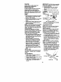
BLADE CARE
For best results mower blades must be
kept sharp. Replace bent or damaged
blades.
IMPORTANT: To ensure proper assembly,
center hole in blade must align with star
on mandrel assembly.
4. Reassemble hex bolt, lock washer
and fiat washer in exact order as
shown.
5. Tighten bolt securely (27-35 Ft. Lbs.
torque).
IMPORTANT:
Blade bolt is grade 8 heat
treated.
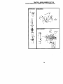
Mandrel Assembly
Trailin Edge Up
Blade Center
Hole
Flat Washer,
Lock Washe
_--- Hex Bolt
*A Grade 8 heat treatedboltcan be identified
by six lineson the bolt head.
TO SHARPEN BLADE
NOTE: We do not recommend sharpening blade - but if you do, be sure the
blade is balanced.
Care should be taken to keep the blade
balanced. An unbalanced blade will
cause excessive vibration and eventual
damage to mower and engine.
• The blade can be sharpened with a file
or on a grinding wheel. Do not attempt
to sharpen while on the mower.
• To check blade balance, you will need
a 5/8" diameter steel bolt, pin, or a cone
balancer. (When using a cone balancer, follow the instructions supplied
with balancer.)
NOTE: Do not use a nail for balancing
blade. The lobes of the center hole may
appear to be centered, but are not.
• Slide blade on to an unthreaded
portion of the steel bolt or pin and hold
the bolt or pin parallel with the ground.
If blade is balanced, it should remain in
a horizontal position. If either end of
the blade moves downward, sharpen
the heavy end until the blade is
balanced.
BLADE REMOVAL
I. Raise mower to highest positionto
allow access to blades.
2. Remove hex bolt, lookwasher and flat
washer securingblade.
3. Install new or resharpenedblade with
trailingedge up towards deck as
shown.
5/8" B_d
e
Center Hole
18
BATTERY
Your tractor has a battery charging system
which is sufficient for normal use. However, periodic charging of the battery with
an automotive charger will extend its life.
• Keep battery and terminals clean.
• Keep battery bolts tight.
• Keep small vent holes open.
• Recharge at 6-10 amperes for 1 hour.
NOTE: The original equipment battery on
your tractor is maintenance free. Do not
attempt to open or remove caps or covers.
Adding or checking level of electrolyte is
not necessary.
TO CLEAN BATTERY AND TERMINALS
Corrosion and dirt on the battery and
terminals can cause the battery to "leak"
power.
1. Open battery box door.
2. Disconnect BLACK battery cable first
then RED battery cable and remove
battery from tractor.
•3. Rinse the battery with plain water and
dry.
4. Clean terminals and battery cable
ends with wire brush until bright.
5. Coat terminals with grease or petroleum jolly.
6. Reinstall battery (See "REPLACING
BATTERY" in the SERVICE AND
ADJUSTMENTS section of this
manual).
V-BELTS
Check V-belts for deterioration and wear
after 100 hours of operation and replace
if necessary. The belts are not adjustable.
Replace belts if they begin to slip from
Change the oil after every 50 hours of
operation or at least once a year If the
tractor is not used for 60 hours in one
year.
Check the crankcase oil level before
starting the engine and after each eight
(8) hours of operation. Tighten oil fill cap/
dipstick securely each time you check the
oil level.
TO CHANGE ENGINE OIL
Determine temperature range expected
before oil change. All oil must meet API
service classification SF-SJ.
• Be sure tractor is on level surface.
• Oil will drain more freely when warm.
• Catch oil in a suitable container.
1. Remove oil fill cap/dipstick. Be careful
not to allow dirt to enter the engine
when changing oil.
2. Remove drain plug.
3. After oil has drained completely,
replace oil drain plug and tighten
securely.
4. Refill engine with oil through oil fill
dipstick tube. Pour slowly. Do not
overfill. For approximate capacity see
=PRODUCT SPECIFICATIONS"
section of this manual.
5. Use gauge on oil fill cap/dipstick for
checking level. Insert dipstick into the
tube and rest the oil fill cap on the
tube. Do not thread the cap onto the
tube when taking reading.
Keep oil
at =FULL" line on dipstick. Tighten cap
onto the tube securely when finished.
I, Cover Knob
Air Cleaner
Cover _
wear.
_
'_,
_
/
TRANSAXLE COOLING
Keep transaxle free from build-upof dirt
and chaffwhichcan restdctcooling.
Foam _-_
PreCleaner _--
Only use high quality detergent oil rated
with API service classification SF-SJ.
Select the oil's SAE viscosity grade
according to your expected operating
temperature.
8AE VISCOSITY GRADE8
/-Grommet
_)(/Air
Cleaner
J Paper Cartridge
_ _
X_Air Cleaner
Air _
_'_'Base
Screen
___
/\
_/Oil Fil Cap/
_
Dipstick
(_ % Oil Drain
Plug
ENGINE
LUBRICATION
•
_
_
_.
Win Nut
_
g
----._L Rubber
_
CLEAN AIR SCREEN
Air screen must be kept free of dirt and
chaff to prevent engine damage from
overheating. Clean with a wire brush or
compressed air to remove dirt and
stubborn dried gum fibers.
19
CLEAN AIR INTAKE/COOLING AREAS
To insure propercooling,make sure the
grass screen,coolingfins, and other
externalsurfacesof the engine are kept
clean at all times.
Every 100 hours of operation(more often
under extremelydusty,dirtyconditions),
removethe blower housingand other
coolingshrouds.Clean the coolingfins
and externalsurfacesas necessary.Make
sure the coolingshroudsare reinstalled.
NOTE: Operatingthe engine with a
blockedgrass screen, dirtyor plugged
coolingfins, and/or coolingshrouds
removedwill cause engine damage due
to overheating.
AIR FILTER
Yourengine will not run properlyusinga
_ilii dirtyair filter. Clean the foam pre-cleaner
after every25 hoursof operationor every
season. Service paper cartddgeevery
100 hoursof operationor every season,
whicheveroccursfirst.
Service air cleaner more often under
dusty conditions.
1. Remove knob and cover.
2. Remove wing nut and air cleaner from
base.
TO SERVICE PRE-CLEANER
3. Slide foam pre-cleaner off cartridge.
4. Wash it in liquid detergent and water.
5. Squeeze it dry in a clean cloth. Allow
it to dry.
6. Saturate it in engine oil. Wrap it in
clean, absorbent cloth and squeeze to
remove excess oil.
TO SERVICE CARTRIDGE
• Replace a dirty, bent, or damaged
cartridge.
NOTE: Do not wash the paper cartridge
or use pressurized air, as this will damage
the cartridge.
7. Reinstall the pre-cleaner (cleaned and
oiled) over the paper cartddge.
8. Reassemble air cleaner, wing nut,
cover and tighten knob securely.
ENGINE OIL RLTER
Replace the engine oil filter every season
or every other oil change ff the tractor is
used more than 100 hours in one year.
1. Drain oil from engine crankcase (See
=TO CHANGE ENGINE OIL" in this
section of this manual, through step
remove drain plug).
2. Remove oil filter and wipe off filter
adapter,
3. Apply e thincoatingof new engine oil
to the rubbergasket on replacement
oil filter.
4. Installreplacementoilfilteron filter
adapter.Tum oil filter clockwiseuntil
rubber gasket contactsthe filter
adapter, then tightenfilter an additional 112rum.
5. Fill crankcasewith new oil (See =TO
CHANGE ENGINE OIL"in this section
of this manual). For approximate
capacitysee "PRODUCT SPECIFICATIONS" sectionof this manual.
6. Start the engine and checkfor oil
leaks. Correct any leaks before
placingengine into full operation.
_Oil
Filter
MUFFLER
Inspectand replacecorrodedmufflerand
spark arrester(if equipped)as it could
create a fire hazard and/ordamage.
SPARK PLUGS
Replace spark plugsat the beginningof
each mowingseason or after every 100
hoursof operation,whicheveroccursfirst.
Spark plug type and gap settingare
shownin =PRODUCT SPECIFICATIONS"
sectionof this manual.
IN-LINE FUEL FILTER
The fuel filtershouldbe replacedonce
each season. If fuel filterbecomes
clogged,obstructingfuel flow to carburetor, replacementis required.
1. With engine cool, remove filter and
plugfuel line sections.
2. Place new fuel filter in positionin fuel
line with arrow pointingtowards
carburetor.
3. Be sure there are no fuel line leaks
and clamps are properlypositioned.
4. Immediatelywipe up any spilled
gasoline.
Clamp
Fuet Filter --_
2O
amp
CLEANING
• Cleanengine,
battery,
seat,finish,etc.
ofallforeign matter.
• Keep finishedsurfacesand wheels free
of all gasoline,oil, etc.
• Protectpaintedsurfaces with automotivetype wax.
We do not recommend using a garden
hose to clean your tractor unless the
electrical system, muffler, air filter and
carburetor are covered to keep water out.
Water in engine can result in a shortened
engine life.
CAUTION: BEFORE PERFORMING ANY SERVICE OR ADJUSTMENTS:
1. Depressclutch/brakepedal fully and set parkingbrake.
2. Place gearshiftlever in neutral(N) position.
3. Place attachmentclutch in =DISENGAGED"position.
4. Turnignitionkey "OFF" and removekey.
5. Make sure the blades and all movingparts have completelystopped.
6. Disconnectspark plugwire from spark plug and place wire where it cannot
come in contact with plut).
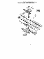
9. Raise lift leverto raise suspension
TRACTOR
arms. Slide mowerout from under
TO REMOVE MOWER
tractor.
Mower willbe easier to remove from the
rightsideof tractor.
IMPORTANT: If an attachmentotherthan
1. Placeattachmentclutchin =DISENthe mowerdeck is to be mountedon the
GAGED"position.
tractor,removethe front linksand hook
2. Move attachmentlift lever forward to
the clutchspringIntO square hole in
lower mowerto its lowest position.
frame.
3, Roll belt off engine pulley.
4. Remove small retainer spdng,and lift
TO INSTALL MOWER
clutchspringoff pulleybolt.
1. Raise attachment lift lever to its
5. Remove large retainer spring, slide
highest position.
collaroff and push housingguide out
2. Slide mower under tractor with
of bracket.
discharge guard to right side of tractor.
6. Disconnectanti-swaybarfrom chassis
3. Lower lift lever to its lowest position.
bracket by removingretainerspring.
4. Install mower in reverse order of
7. Disconnectsuspensionarms from
removal instructions.
rear deck bracketsby removing
retainer springs.
8. Disconnectfront linksfrom deck by
removingretainer springs.
Clutch
Retainer S
Anti-Swa
Retainer Springs
(Both Sides)
Collar
Housing
Large
Spring
Bracket
21
TOLEVEL
MOWER
HOUSING
Adjustthemowerwhiletractor
is parked
onlevelground
ordriveway.
Makesure
tiresarepropedy
inflated
(See"PRODUCTSPECIFICATIONS"
section
ofthis
manual).Iftiresareoveror
underinflated,
youwillnotpropedy
adjust
yourmower.
SIDE-TO-SIDE
ADJUSTMENT
• Raise mower to its highest position.
• At the midpoint of both sides of mower,
measure height from bottom edge of
mower to ground. Distance =A" on
both sides of mower should be the
same or within 1/4" of each other.
• If adjustment is necessary, make
adjustment on one side of mower only.
• To raise one side of mower, tighten lift
link adjustment nut on that side.
• To lower one side of mower, loosen lift
link adjustment nut on that side.
NOTE: Each full turn of adjustment nut
will change mower height about 1/8".
• Recheck measurements after adjusting.
Bottomedge of
Bottomedge of
mower to
mowerto
ground _
• If linksare not equal in length,adjust
one linkto same length as otherlink.
• To lowerfront of mower loosennut =E"
on bothfront linksan equal numberof
turns.
• When distance"D" is 1/8"to 1/2" lower
at front than rear, tightennuts =F"
againsttrunnionon bothfrontlinks.
• To raisefront of mower, loosennut "F"
from trunnionon bothfront links.
Tightennut "E"on bothfront linksan
equal number of turns.
• When distance"D" is 1/8"to 1/2" lower
at frontthan rear, tightennut "F" against
trunnionon bothfront links.
• Recheck side-to-sideadjustment.
ndrel
Both FrontLinksShouldbe Equal in Length
ground
SuspensionArm
Nut ,,_Nut
AdjustmentNut_
-LiftLink
'_
FRONT-TO-BACK ADJUSTMENT
IMPORTANT: Deck must be level side-toside.If the following front-to-back adjustment is necessary, be sure to adjust both
front links equally so mower will stay
level side-to-side.
To obtain the best cutting results, the
mower housing should be adjusted so
that the front is approximately 1/8" to 1/2"
lower than the rear when the mower is in
its highest position.
Check adjustment on right side of tractor,
Measure distance =P" directly in front and
behind the mandrel at bottom edge of
mower housing as shown.
• Before making any necessary adjustments, check that both front links are
equal in length. Both links should be
approximately 10-3/8".
"E"
Trunnio_=__
Front Links
22
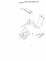
TO REPLACE MOWER BLADE DRIVE
BELT
With Parking Brake
"Engaged"
The mower blade drive belt may be
replaced without tools. Park the tractor on
level surface. Engage parking brake.
BELT REMOVAL 1. Remove mower from tractor (See "TO
REMOVE MOWER" in this section of
this manual).
2. Work belt off both mandrel pulleys and
idler pulleys.
3. Pull belt away from mower.
BELT INSTALLATION 4. Install new belt in reverse order of
removal.
5. Make sure belt is in all pulley grooves
and inside all belt guides.
6. Install mower in reverse order of
removal instructions.
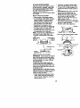
Nut =A"
_ng
TO REPLACE MOTION DRIVE BELT
Park the tractoron level surface. Engage
parkingbrake. Forassistance,there is a
belt installationguide decal on bottom
side of leftfootrest.
I. Remove mower(See "TO REMOVE
MOWER" in thissectionof this
manual.)
2. Remove belt from stationaryidler and
clutchingidler.
3. Pullbelt slacktowardrear of tractor.
Remove belt upwardsfrom transaxle
pulley by deflectingbelt keepers.
4. Pullbelt towardfrontof tractorand
remove downwardsfrom around
engine pulley.
5. Installnew belt by reversingabove
procedure.
Mandrel
Pulley
TO ADJUST BRAKE
Your tractor is equipped with an adjustable brake system which is mounted on
the right side of the transaxle.
If tractor requires more than six (6) feet
stopping distance at high speed in
highest gear, then brake must be adjusted.
1. Depress clutch/brake pedal and
engage parking brake.
2. Measure distance between brake
operating arm and nut "A" on brake
rod.
3. If distance is other than 1-1/2", loosen
jam nut and tum nut "A" until distance
becomes 1-1/2". Retighten jam nut
against nut "A".
4. Road test tractor for proper stopping
distance as stated above. Readjust if
necessary. If stopping distance is still
greater than six (6) feet in highest
gear, further maintenance is necessary. Contact a Sears or other
qualified service center.
Transaxle
23
TRANSAXLE GEAR SHIFT LEVER
NEUTRAL ADJUSTMENT
The transaxle should be in neutral when
the gear shift lever is in neutral (N) (lock
gate) position. The adjustment is preset at
the factory; however, if adjustment is
needed, proceed as follows:
1. Make sure transaxle is in neutral (N).
NOTE: When the tractor rear wheels
move freely, the transaxle is in neutral.
2. Loosen adjustment bolt in front of the
right rear wheel.
3. Position the gear shift lever in the
neutral (N) position.
4. Tighten adjustment bolt securely.
NOTE: If additional clearance is needed
to get to adjustment bolt, move mower
deck height to the lowest position.
Gearshift Lever
Neutral Lock Gate
AdjustmentBolt
TO ADJUST STEERING WHEEL ALIGNMENT
If steedng wheel crossbars are not
horizontal (left to right) when wheels are
positioned straight forward, remove
steering wheel and reassemble per
instructions in the Assembly section of
this manual.
FRONT WHEEL TOE-IN/CAMBER
The front wheel toe-in and camber are
not adjystal_e on your tractor. If damage
has occurred to affect the front wheel toein or camber, contact a Sears or other
qualified service center.
TO REMOVE WHEEL FOR REPAIRS
1. Blockup axle securely.
2. Remove axle cover, retainingring and
washersto allow wheel removal (rear
wheel containsa square key - Do not
lose).
3. Repair tire and reassemble.
NOTE: On rear whsels only: align
grooves in rear wheel hub and axle.
Insertsquare key.
4. Replace washers and snap retaining
dng securelyin axle groove.
5. Replace axle cover.
NOTE: To seal tire puncturesand prevent
flat tires due to slow leaks, tire sealant
may be purchasedfrom yourlocal parts
dealer.Tire sealant also preventstire dry
rot and corrosion,
Washer ,_
Retaining _
_,__.
Ax,o
R,n I\ Irf \l
Cover
Square Key
(Rear Wheel Only)
TO START ENGINE WITH A WEAK
BATTERY
& 9.qJ'nON:Le.ad-ac_dbe.ttedes generate
e_oK)s_,egases. _sep sparks, name ana
smoking materialsaway from batteries.
Always wear eye protectionwhen around
batteries.
Ifyour battery is too weak tostartthe engine, it
shouldbe recharged. (See "BATTERY"in the
MAINTENANCE section of Ihis manual).
If "jumper cables"are used for emergency
starting,follow this procedure:
IMPORTANT: Yourtractoris equippedwith a
12 volt negativeg ounded system.The other
vehicel must alse be a 12 volt negative
grounded system. Do not use your tractor
batteryto startother vehicels.
TO A'I-rACH JUMPER CABLES 1. Connect each end of the RED cable to
the POSITIVE (+) terminal of each
battery, taking care not to short
against chassis.
2. Connect one end of the BLACK cable
to the NEGATIVE (-) terminal of fully
charged battery.
3. Connect the other end of the BLACK
cable to good CHASSIS GROUND,
away from fuel tank and battery.
TO REMOVE CABLES, REVERSE ORDER 1. BLACK cable first from chassis and
then from the fully charged battery.
2. RED cable last from both batteries.
24
PositiveTerminal
NegativeTerminal
Hex
Bolt
Positive (Red) Cable
Positive Terminal
REPLACING
Negative Terminal
BATTERY
_]kCAUTION: Do not short battery
terminals by allowing a wrench or any
other object to contact beth terminals at
the same time. Before connecting battery,
remove metal bracelets, wristwatch
bands, rings, etc.
Fositive terminal must be connected first
to prevent sparking from accidental
grounding.
I. Lift seat pan to raised position and
open battery box door.
2. Disconnect BLACK battery cable first
then RED battery cable and carefully
remove battery from tractor.
3. Install new battery with terminals in
same position as old battery.
4, First connect RED battery cable to
positive (+) terminal with hsx bolt and
keps nut as shown, Tighten securely.
5. Connect BLACK grounding cable to
negative (-) terminal with remaining
hex bolt and keps nut. Tighten
securely.
6. Close battery box door.
Negative (Black)
Cable
TO REPLACE HEADLIGHT BULB
1. Raise hood.
2. Pull bulb holder out of the hole in the
backside of the grill
3. Replace bulb in holder and push bulb
holder securely back into the hole in
the backside of the grill.
4. Close hood.
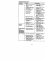
INTERLOCKS AND RELAYS
Loose or damaged wiring may cause your
tractor to mn poorly, stop running, or
prevent it from starting.
• Check wiring. See electrical wiring
diagram in the Repair Parts section.
TO REPLACE FUSE
Replace with 20 amp automotive-type
plug-in fuse. The fuse holder is located
behind the dash.
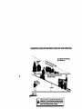
TO REMOVE HOOD AND GRILL
ASSEMBLY
1. Raise hood.
2. Unsnap headlightwire connector.
3. Stand in frontof tractor. Grasp hood at
sides,tilttowardengine and lift off of
tractor.
4. To replace, reverse above procedure.
Hood
Headlight Wire
Connector
Batter
Door Box
25
ENGINE
Maintenance,
repair,or replacement
of the
emissioncontroldevicesandsystems,which
are beingdoneat thecuatomemexpense,
may be pe_nued byany non-madengine
repairestablishment
or individual.
Wananty
repairsmustbe performedbyan authorized
engine rnanufecfurefs
serviceoutlet.
TO ADJUST THROTTLE CONTROL
CABLE
Thethrottlecontrolhasbeenpresetat the
factoryandadjustmentshouldnotbe
necessary.
Checkadjustment
as described
belowbelomloosening
cable.
Ifadjustment
is
necessary,
proceed
as follows:
I. Withenginenotrunning,
move throttle
controlleverfrom slowto chokel:x:_lon.
Slowlymoveleverfrom choketo fast
position.
2. Checkto see if holeinthrotUeleverand
holein speedcontrolbracketare aligned.
3. If holesare notaligned,loosenceble
clampscrewand alignthe holesby
insertinga pencilor a 114"drillbitthrough
beth holes.
4. Pullthrottlecableup to removeslackand
tightencabledamp screw. Remove
alignmentpencilor drillbit.
TO ADJUST CARBURETOR
The carburetor
hasbeen presetat the factory
and adjusbnent
shouldnetbe necessary.
However,minoradjustmentmaybe required
tocompensate
for differences
in fuel,
temperature,
altitudeor load.Ifthecarburetor
doesneedadjustment,
proceedas follows:
In general,turningthe adjustingneedlesIn
(clockwise)
decreasesthesupplyoffuelto
the enginegivinga leanerfueVairmixture.
Turningthe adjustingneedlesout (counterclockwise)
increasesthesupplyof fuelto the
enginegivinga _cherfuel/airmixture.
IMPORTANT:Damageto the needlesand
seatsin carburetor
may resultif turnedintoo
tight.
NOTE: The carburetor
on this engineislow
emis_on,It is squippedwithan idlefuel
adjustingneadlewitha limitercap,which
allowssomeadjusbnent
withinthe limits
allowedbythecap.Do net attemptto rernove
the limitercap.The limitercap canootbe
removedwithoutbreakingthe adjusting
needle.
1. Be sureyouhavea cleanairfilter andthe
throttlecontrolcable is adjustedproperly
(see above).
2. Startengine and allow to warm for itve
minutes. Make adjustments with engine
runningand shifl/moitoncontrol lever in
neutral (N) pos'#_on,
3. Idle soeed setting_- Wifh threltle control
lever in slow position,engine shouldidle
at 1750 RPM. If engine idlestoo slowor
last, tum idle speed adjustingscrew in or
out untilcorrect idle is attained.
4. Idle fuel needle setting- With throttle
controllever in slow p_sitlon,turn idle fuel
adjustmentneedle in (cleakwise) until
engine begins to die and then turn out
(countemloakwise)until
engine runs
rough. Turn needle to a point midway
between those two positions.
5. Recheck idle speed. Readjust if necessan/.
ACCELERATION TEST 6. Move throttle control leverfrom slow to
fast pos_on. If engine hesitatesor dies,
turn idle fuel adjustingneedle out
(counterclockwise) 1/8 rum. Repeat test
and continue to adjust, if necessary,until
engine accelerates smoothly.
High speed stop is factory adjusted. Do
not adjust - damage may result.
IMPORTANT: Never tamper with the
engine governor, which is factory set for
proper engine speed. Overspeeding the
engine above the factory high speed
setting can be dangerous. If you think the
engine-governed high speed needs
adjusting, contact a Sears or other qualified
service center, which has proper equipment and experience to make any
necessary adjustments.
26
Cable _"-----_
Clamp
screw
I
Speed C_ontrol_']_,_J
J
_ver
IdleSpeed
------.-._
Adjusting--------_r-------_
Screw
I_'_A_I
Idle Fuel
I_'--_
Adjusting -----"_ [_
Needle
I
II !_%'_,
_
I--_'_I
___
Immediatelyprepareyour tractorfor
storageat the end of the season or if the
tractorwill not be used for 30 days or
more.
CAUTION: Never storethe tractorwith
gasoline in the tank inside a building
where fumes may reach an open flame or
spark. Allowthe engine to cool before
storingin any enclosure.
TRACTOR
Remove mower from tractorfor winter
storage. When moweris to be storedfor
a periodof time, clean it thoroughly,
remove all dirt, grease, leaves,etc. Store
in a clean, dry area.
1. Clean entiretractor (See "CLEANING"
in the Maintenancesectionof this
manual).
2. Inspectand replacebelts, if necessary
(See belt replacementinstructionsin
the Service and Adjustmentssection
of this manual).
3. Lubricateas shownin the Maintenance sectionof this manual.
4. Be sure that ell nuts,boltsand screws
are securelyfastened. Inspectmoving
partsfor damage, breakage and wear.
Replace if necessary.
5. Touch up all rustedor chippedpaint
surfaces;sand lightlybefore painting.
BATrERY
• Fullychargethe batteryfor storage.
After a periodof time in storage,battery
may requirerecharging.
• To help prevent corrosionand power
leakage dudng long periodsof storage,
batterycables shouldbe disconnected
and battery cleaned thoroughly(see
"TO CLEAN BATTERY AND TERMINALS" in the Maintenancesectionof
this manual).
• After cleaning, leave cables disconnected and place cables where they
cannotcome in contactwith battery
terminals.
• If batteryis removedfromtractorfor
storage, do not store batterydirectlyon
concreteor damp surfaces.
ENGINE
FUEL SYSTEM
IMPORTANT: It is importantto prevent
gum depositesfrom forming in essential
fuel systemparts such as carburetor,fuel
hose, or tank duringstorage.
Also, expedance indicates that alcoh
blended fuels (called gasohol or usir
ethanol or methanol) can attract mois
which leads to separation and formal
of acids during storage. Acidic gas c_
damage the fuel system of and engin
while in storage.
1. Drain the fuel tank.
2. Start the engine and let it run until
fuel lines and carburetor are empt
• Never use engine or carburetor cl(
products in the fuel tank or perman
damage may occur.
• Use fresh fuel next season.
NOTE: Fuel stabilizer is an acceptat
alternative in minimizing the formatio
fuel gum deposits during storage, Ac
stabilizer to gasoline in fuel tank or
storage container. Always follow the f
ratio found on stabilizer container. RL
engine at least 10 minutes after addir
stabilizer to allow the stabilizer to reaq
the carburetor. Do not drain the gas t=
and carburetor if using fuel stabilizer.
ENGINEOIL
Drain oil (with engine warm) and repl
with clean engine oil. (See =ENGINE'
the Maintenance section of this manu
CYUNDER(S)
1. Remove spark plug(s).
2. Pour one ounce of oil through spa
plug hole(s) into cylinder(s).
3. Turn ignition key to "START" posit
for a few seconds to distribute oil.
4. Replace with new spark plug(s).
OTHER
• Do not store gasoline from one se_
to another,
• Replace your gasoline can if your i
starts to rust. Rust and/or dirt in yol
gasoline will cause problems.
• If possible, store your tractor indool
and cover it to give protection from
and dirt.
• Cover your tractor with a suitable
protective cover that does not rata
moisture. Do not use plastic. P_as_
cannot breathe which allows cond,
sation to form and will cause your
tractor to rust.
IMPORTANT:
Never cover tractor wl
engine and exhaust areas are still wz
27
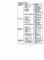
TROUBLESHOOTING
CHART
PROBLEM
Will not start
CAUSE
CORRECTION
1. Fill fuel tank.
2. See"TO START ENGINE"
in Operationsection.
3. Wait several minutes
beforeattemptingto start.
4. Bad spark plug.
4. Replace spark plug.
5. Dirty air filter.
5. Clean/repleceair filter,
6. Dirty fuel filter.
6. Replace fuel filter.
7 Water in fuel.
7. Drain fuel tank and
carburetor,refilltank with
fresh gasolineand replace
fuel filter.
8. Loose or damaged wiring.
8. Check all wiring.
9. Carburetor out of adjustment, 9. See "To AdjustCarburetor"
in Service Adjustments
section.
10.Contact a Sears or other
10. Engine valves out of
1, Out of fuel.
2. Engine not "CHOKED"
properly.
3. Engine flooded.
adjustment.
Hard to start
Enginewill not
turn over
1. Dirty air filter.
2. Bad spark plug.
3. Weak or dead battery.
qualifiedservice center.
Cleanirapleceair filter.
Replace spark plug.
Recharge or replace
battery.
Replace fuel filter.
Drain fuel tank and refill
with fresh gasoline.
Check all wiring.
See "To Adjust Carburetor"
in Service Adjustments
section.
Contacta Sears or other
qualifiedservice center.
4. Dirty fuel filter.
5. Stale or dirty fuel.
4.
5.
6. Loose or damaged widng.
7. Carburetor out of adjustment
6.
7.
8. Engine valves out of
adjustment.
8.
1. Clutch/brake pedal not
depressed.
2, Attachment clutch is
engaged.
3. Weak or dead battery.
9. Faulty operator presence
switch(es).
1. Depress clutch/brake
pedal.
2. Disengage attachment
clutch.
3. Recharge or replace
battery.
4. Replace fuse.
5. Clean battery terminals.
6. Check all wiring.
7. Check/replase ignition
switch.
8. Check/raplace solenoid or
starter.
9. Contact a Sears or other
qualified service center.
1.
2.
3.
4.
t.
2.
3.
4.
4.
5.
6.
7.
Blown fuse.
Corroded battery terminals.
Loose or damaged wiring.
Faulty ignition switch.
8. Faulty solenoid or starter.
Engine clicks but
will not start
I
1.
2.
3.
Weak or dead battery.
Corroded battery terminals.
Loose or damaged wiring.
Faulty solenoid or starter.
28
Recharge or replace battery
Clean battery terminals.
Check all wiring,
Check/replace solenoid or
starter.
TROUBLESHOOTING
PROBLEM
Loss of power
CHART
CAUSE
CORRECTION
1. Cutting too much grass/too
fast.
2. Throttle in "CHOKE"
position.
3. Build-up of grass, leaves
and trash under mower.
4. Dirty air filter.
5. Low oil level/dirty oil.
6. Faulty spark plug.
7. Dirty fuel filter.
8. Stale or dirty fuel.
9. Water in fuel.
10.Spark plug wire loose.
1.Dirty engine air screen/fins.
i 12. Dirty/clogged muffler.
113.Loose or damaged wiring.
14.Carburetor out of
adjustment.
15.Engine valves out of
adjustment.
Excessive
vibration
1. Worn, bent or loose blade.
2. Bent blade mandrel.
3. Loose/damaged part(s).
1. Set in "HigherCut"position/
reduce speed.
2. Adjustthrottlecontrol.
3. Clean underside of mower
housing.
4. Clean/replace air filter.
5. Check oil level/change oil.
6. Clean and regap or change
spark plug.
7. Replace fuel filter.
8. Drain fuel tank and refill with
fresh gasoline.
9. Drain fuel ta_k and carbura
tor, refill tank with fresh
gasoline and replace fuel
filter.
10.Connect and tighten spark
plug wire.
11.Clean engine air screen/fins.
12. Clean/replace muffler.
13.Check all wiring.
14. See =To Adjust Carburetor"
in Service Adjustments
section.
15.Contact a Sears or other
qualified service center.
1. Replace blade.
Tighten blade bolt.
2. Replace blade mandrel,
3. Tightenloosepart(s).
Replace damaged parts.
Enginecontinuas
to run
when operator
leaves seat with
with attachment
clutch engaged
1. Faulty operator-safety
presencecontrolsystem.
1. Check wiring, switches and
connections. If not
contact a Sears or other
qualified service center.
Poorcut-uneven
1. Worn, bent or looseblade.
1. Replace blade. Tighten
blade bolt.
2. Level mower deck.
3. Clean undersideof mower
housing.
4. Replace blade mandrel.
5. Clean aroundmandrelsto
open vent holes.
2. Mower deck not level.
3. Buildup of grass, leaves,
and trash under mower.
4. Bent blade mandrel.
5. Clogged mower deck vent
holes from buildup of
grass, leaves, and trash
around mandrels.
29
TROUBLESHOOTING
PROBLEM
Mowerbladeawill
not rotate
Poor grass
discharge
CHART
CAUSE
CORRECTION
!1, Obstruction inclutch
mechanism.
2. Worn/damaged mower
ddve belt,
3. Frozen idler pulley.
4. Frozen blade mandrel.
1, Engine speed too slow.
2. Travel speed too fast.
3. Wet grass.
4. Mower deck not level.
5. Low/uneventire air
pressure.
6. Wom, bent or looseblade.
7. Buildup of grass, leaves
and trash under mower.
8. Mower drive belt worn.
9. Blades improperly installed.
10.Improper blades used.
11.Clogged mower deck vent
holes from buildup of grass,
leaves, and trash around
mandrels.
Pleadlight(a) not
_vorking
[if so equipped)
1,
2.
3.
4.
Switch is"OFF".
Bulb(s) burned out.
Faulty light switch.
Loose or damaged wiring.
5. Blown fuse.
Battery will not
¢harge
1. Bad battery cell(s).
2. Poor cable connections.
3. Faulty regulator
(if so equipped).
4. Faulty alternator.
Engine "backfires'
when turning
engine "OFF"
1. Remove obstruction,
2. Replace mower drive belt,
3. Replace idler pulley.
4. Replace blade mandrel,
1. Place throttle control in
"FAST" position.
2. Shift to slower speed.
3. Allow grass to dry before
mowing.
4. Level mower deck.
5. Check tires for proper air
pressure.
6. Replace/sharpen blade.
Tighten blade bolt.
7. Clean underside of mower
housing.
8. Replace mower ddve belt.
9. Reinstall blades sharp edge
down.
10. Replace with blades listed
in this manual.
11.Clean around mandrels to
open vent holes.
1.
2.
3.
4.
Turn switch "ON".
Replace bulb(s).
Check/replace light switch.
Check wiring and connec
tions.
5. Replace fuse.
t. Replace battery.
2. Check/clean all connec
tions.
3. Replace regulator.
4. Replace alternator.
1. Enginethrottlecontrolnot
set at =SLOW" position
for 30 secondsbefore
stopping engine.
30
1. Move throttle control to
=SLOW" position and allow
to idle for 30 seconds befor_
stopping engine.
SCHEMATIC
TRACTOR
-- MODELNUMBER
917.271133
IGNITION SWITCH
POSITION
CIRCUIT
OFF
M+G+A1
RUN4.1GHT B+A1
START
RUN
B+B+AI
S + A1
"MAKE"
In
-_"
NONE
A2+L
NONE
RELAY
NON-REMOVABLE
CONNECTIONS
_1
REMOVABLE
CONNECTIONS
WIRING INSULATED CUPS
NOTE: IF WIRING INSULATED CLIPS WERE REMOVED FOR
SERVICING OF UNIT, THEY SHOULD BE REPLACED TO
PROPERLY SECURE YOUR WIRING,
31
TRACTOR - - MODEL NUMBER 917.271133
ELECTRICAL
t _
TRACTOR - - MODEL NUMBER 917.271133
ELECTRICAL
KEY PART
NO. NO.
DESCRIPTION
1
2
8
16
21
22
24
25
26
27
28
29
30
33
40
41
42
43
45
52
81
BatteP/
Bolt, Hex 114-20 x 3/4
Case Battery
Switch Intedock
Hamess, Ught Sod(at (w/4152J)
IJght Bulb
Cable, Battery
Cable, Battery
Fuse
Nut Keps Hex 1/4-20 Unc
Cable,Ground
Switch, Seat
Switch, I_ition
Key, Molded
Harness, Ignition
Bblt B_kFin Hex 1/4-20 UNG x 1/2
Cover, Temtinal
Solenoid
Ammeter
Protec5on Wire Loop (Hour Meter)
RelayAsm
163465
74760412
156417
161343
166182
4152J
4799J
146147
175158
73510400
4207J
160784
175566
140403
170219
71110408
131563
175141
122822)(
141940
109748X
NOTE: Allcomponentdimensionsgiven in U,S. inches
1 inch= 25.4 rnm
33
TRACTOR -- MODEL NUMBER 917.271133
CHASSIS AND ENCLOSURES
34
TRACTOR -- MODEL NUMBER 917.271133
CHASSIS AND ENCLOSURES
KEY
NO.
PART
NO.
DESCRIPTION
1
2
3
5
9
10
11
!2
13
17
18
25
26
28
29
30
31
37
38
51
52
53
54
55
57
58
60
64
74
t14
t13
142
143
144
145
206
207
208
211
212
-.
16g630
169061
17060612
155272
168337X013
STD533710
155927
145660
172108
t 44983X558
126938X
19131312
ST[To41437
156725X558
155217X599
164918X558
139976
174_508
169834
73800400
19091416
145201
161464
1_
STD552507
150127
72140606
154798
STD541437
158112
17060620
165867
154966
t 54207
156524
170165
1767G508
17676608
145212
165919
5479J
Chassis
Dmwber
Screw 3/8-16 x 3/4
Bumper Hoo_Dash
Dash
Bolt, Carriage 3/8-16xl
Panel, Dash, LH
Cltp 13nnerman Gillie P/L
Panel, Dash, RH
Hood Assembly
Bumber Hood
Washer 13/32 x 13/t6 x 12 Gauge
Locknut, Hex, with Insert 3_-16 UNC
G riile
Lens, Gdlle
Fender/Footrest
Bracket, Fender/Suppod
Screw, Thdr_. 5/16-18 x 1/2 TYT
Pivot Bracket Assem_y, LH, Mower, Rear
Nut Lock W/Insert 1/4 - 20 UNC
Washer 9/32 X 7/8 X 16 Ga.
Bracket Grille Pickoff LH
Screw, Hex Wshd #8-18 x 7/8
Bracket Gd{le PIckoff RH
Bolt FinHex 1/4 -20 UNC X.75
Air Duct
Bolt Rdhd Sqnk 3/8-16 UNC x 3/4
Dash Lower STLT
Nut Crownlock 3/6-16 UNC
Keeper Belt
Screw 3/8-16 x 1-1/4
Plate Rektforcement STLT
Bracket Swaybar Chassis
Bracket Footrest STLT
Rod Pivot Chassis/Hood
Bolt Shoulder 5/16-18TT
Screw Thdrol 5/16-18 x t/2
Screw Thdro_ 3/8-16 x 1/2
Nut Flange Hex
Insert Lens
Plug Button
NOTE: Allcomponentdimensionsg_venIn U.S. inches
1 Inch = 25.4 mm
35
TRACTOR - - MODEL NUMBER 917.271133
GROUND DRIVE
57
32
26
36
27
TRACTOR - oMODEL NUMBER 917.271133
GROUND DRIVE
::Z
KEY
NO.
PART
NO,
1
........
2
3
4
5
6
8
10
11
13
14
16
18
19
21
22
24
25
26
27
28
29
30
32
34
35
36
37
38
39
40
41
42
47
48
49
50
51
52
53
55
56
57
59
61
146682
123666X
12000028
121520X
17060512
165866
STD561210
165701X
74550412
10040400
BTD541431
STD523710
STD541437
106933X
130804
STC541237
106888X
ST[7o510_7
S_1210
145204
71673
169592
STD523107
155071
120183X
STD551662
STD571810
131494
BTD533727
4470J
165838
19131312
127783
154407
I_X
STD523715
STD541437
STD541431
1G5710X
105709X
STC523712
130601
16_691
17060612
DESCRIPTION
Transaxle (See Breakdown )
Peedess 206-545C
Spdng, Return, Brake
Pulley, Transaxle
Ring, Retainer
Strap, Torque
Screw 5/16-18 x 3/4
RodShlfter Feoder STLT
Pin, Cotter
Washer, Shltt Rate
Bolt 1/4-28 UNF W/Patch Gr. 8
Washer Lock Hvy Helical
Nut Lock Hx W/Ins 5/16-16 x Gr.5
Bolt Fin Hex 3/8-16UNC x 1 Gr. 5
Nut
Knob
Rod, Brake
Nut
Spring, Brake Rod
Washer
Rn
Rod, Pattdng Brake
Cap, Parking Brake
Bracket, Transaxle
Bolt
Shaft AseembJy, Foot Pedal
Bearlng, Nylon
Washer
ROll Rn
Pulley, idler, Flat
Bolt
Spacer, Split 395 x .59
Keeper, Belt, idler
Washer 13/32 x 13/16 x12 Ge.
Pulley, Idler, V-Groove, Plastic
Beticrenk Clutch Gmd Dry Stl
Retainer, Belt
Bult
Nut Crown Lock 3/8-16 UNC
Nut Crown Lock 5/16-18 UNC
Link, Clutch
Spdng, Clutch Retum
Bolt Fin Hex 3/8-16 x 1-1/4
V-Bett, Ground Drive
Keeper, Belt, Center Span
Screw 3/8-16 x 3/4
KEY
NO.
PART
NO.
DESCRIPTION
62
63
64
65
66
70
72
74
75
76
77
78
79
80
81
82
83
84
85
89
90
96
112
113
116
145
150
161
156
158
159
161
162
163
164
165
166
168
169
170
197
198
2(_
8883R
140186
71170764
S'10551143
154778
134683
1913_012
137057
121746X
STD581075
123583)(
121748X
S_
145090
165592
165711
19171216
166231
150_60
158391X428
124346X
STD624003
19091210
127285X
72110610
7449(To40
165850
19133210
166002
165589
165494
72140406
73680400
74780416
19091010
165_3
166880
165492
165580
173898
169613
169593
72110612
Cover, Pedal
Pulley, Engine
Bolt, Hex 7/16.20 x 4 Grade 5
Washer
Keeper, Bett, Engine, FOOlProof
Guide, Mower Ddve Belt, R.H.
Washer 13/32 x 1-1/4 x 12 Ga.
Specer, Axle
Washer 25/32 x 1-1/4 x 16 Ge.
E-Ring
Key, Square 2.0 x ,1845/1865
Washer 25/32 x 1-5/3 x 16 Ga
Key Woodruff
Ann, Shift
Shaft Asm Cross Tapered 660 2tt
Spdng, Torsion
Washer 17/32 x 3/4 x 16 Ga.
IJnk Traneexle
Nut, Nylock
Console, Shitt, STLT
Nut, Selt-Thdlng, Wsh Hd 1/4
Retainer Spring 1"
Washer 9/32 x 3/4 x 10 Ga.
Strap Torque 90 Degrees
B_t Rdhd Sqneck 3/8-16 x 1.25
Bolt, Hex Flghd 5/16-18 Gr. 5
Bushing BellcrankGrd. Drive
Washer 13_2x2x
10Ga.
Washer Srrtad 5/161D x 1.125
Bracket Shift Mount
Hub Tapered Range Shift Lt
Bolt Rdhd Sqnk 1/4-20 x 3/4 Gr.5
Nut Crownlock 1/4-20 Uric
Bolt Hex Fin 1/4_20Unc x 1 Gr 5
Washer 5/8 x .261 x 10 Ga
Bracket Pivot Lever
Screw 5/16-18 x 5/8
Bolt Shoulder 5/16-16 x .561
Plata Fastening Lt
Keeper E_dt Tmnsaxle Pmst/Oana
Nyliner Snap-In
Washer Nytiner
Bolt Carr. SH 3/3-16 x 1-1/2 Gr. 5
NOTE: All component
1 Illch = 25.4 turn
37
dimensions given In U.S. inches
STEERING
TRACTOR
ASSEMBLY
39
- - MODEL
NUMBI::H 917.211133
TRACTOR -- MODEL NUMBER 917.271133
STEERING ASSEMBLY
KEY
NO,
PART
NO.
DESCRIPTION
1
2
3
4
5
6
7
8
9
10
11
13
15
17
18
19
22
23
25
26
27
28
29
30
32
36
37
38
39
40
41
42
43
44
46
47
51
54
62
63
65
66
67
68
79
80
82
85
139768
154427
169840
169839
_66H
121748X
19272016
1200(_(_9
3366R
16_32
STC551137
136518
145212
156546
57079
160_95
1_857
165851
154406
126847X
136874
19131416
17060612
STD561210
130465
155099
152927
139769
19133812
S'rD541537
100711L
145054X428
121749X
153720
121232X
6855M
_
74780520
167902
74780616
160367
154404
72140618
169827
19132012
74950612
169835
133835
SteedngWheel
Front Axle Assembly
Spindle h.ssembly, L,H.
Spindle Assembly, R.H.
Bearing, Race, Thrust, Hardened
Washer 25/32 x 1-5/8 x 16 Gauge
Washer 27/32 x 1-1/4 x 16 Gauge
Ring, Kiip
Beadng, Steedng Column
Unk, Drag
Washer, Loci(
Spacer, Beadng, Front Axle
NuL Hexllange Lock
Shaft Assembly, Steedng
Washer, Thrust .615 x .750 x .033
Support, Shaft
Screw hex Wshhd TOFX
Pftttnan Shaft Assembly
Bracket, Steedng
Bushing, Link, Drag
Gear, Sector
WaSher 13132 x 7/8 x 16 Gauge
Screw 3/6-16 x 3/4
Pin
Rod,Tie
Bushing, Steedng
Screw TT #10-32 x 5 x 3/8 Rathe
Insert, Steedng Wheel
Washer 13/32. x 2-3/8 x 12 Gauge
Lock Nut Center 3/8-24 UNF
Adaptor, Steedng Wheel
Bcot, Steedng Dash p/L MU BIk
Washer 25/32 x 1-1/4 x 16 Gauge
Extension Steedng Non-Adjust
Cap, Splodle
Fitting, Grease
Nut Lock Hx Wrins 5/16-18 UNC
Bolt Fin Hex 5/16-1 ft UNC x 1-1/4
Kit, Steering Assembly, Service
Bolt Fin Hex 3/8-16 un(L x 1 Gr. 5
Spacer Brace Axle
Bearing Arm Plltman
Bolt Rdhd Sq 3/8.16 Unc x 2-1/4
Brace Axte
Washer 13/32 x 1-1/4 x 12 Ga
Bolt Hex Nylon 3/6-16 x 3/4
Bracket Susp Chassis Front
Fastener Christmas Tree
NOTE: All component dimensions given in U,S. inches
1 inch = 25.4 mm
39
TRACTOR - - MODEL NUMBER 917.271133
ENGINE
_101
29
OPTIONAL
EQUIPMENT
Spark Arrester
40
1
TRACTOR -- MODEL NUMBER 917.271133
ENGINE
KEY PART
NO. NO.
DESCRIP'nON
1
2
3
4
13
14
15
15
23
29
31
32
33
37
38
40
44
45
46
62
77
80
81
101
Conb'ol "_rot/oiloke
Screw Hex Thd Cut 1/4-20x5/8 T
Engine (See Breskdown) Kohler Model No. CV461-26504
Muffler
Gasket
Nipple, Pipe 3/8 NPT x 3-1/2
Elbow, Std 90 Degree 3/8-18 Npt
Washer
Shield, BRN/DBR Guard
Arrestor, Sperk
Tank, Fuel
Cap Assembly, Fuel Tank, Vented
Clamp Hose BIk
UneFuel
Plug Oil Drain (See Engine Breakdovm)
Bushing, Snap, Fuel Une
Screw, Hex Washer Head. Thd. Roll 1/4-20 x 3/4
Screw Hexwsh Thdr 3/8-16 x 3/4
Washer, 2/32 x 7/8 x 16 Guage
Washer Lock Hvy Hlcl Spr 5/16
Washer 5/16 x 3/4 x 16 Guage
Bolt, Hex Hd 5/16-18 Unc x 1/2
Nut, Keps Hex 1/4-20 Uric
NutFiangeMB-1.25
170548
17720410
.......
174667
12-041-03
13280328
13200300
STD551231
169837
137180
10920P_X
158990
123487X
137040
.......
124G28X
17670412
17CO0612
1g091416
STD551131
19101216
7476(To08
73510400
M_
NOTE: All component dimensions given in U.S. inches
1 inch = 25.4 mm
41
SEAT ASSEMBLY
TRACTOi_
-. MODEL
KEY PART
NO. NO.
DESCRIPTION
1
2
3
4
5
6
7
8
9
10
11
12
Seat 3450 81k/blk Craftsman
Bracket Pnt Pivot Seat (blk)
Bolt Fir= Hex 3/8-16ullc X 1
Washer 13/32 X 3/4 X 10 Ga
Clip Push In Hinged
Nut Hex Lock w/Ins 3J8-16 Uric
Spring Seat Cprsn 2 250 SIk Zi
Screw 3/8-16 x 1.5 SMGML
Washer 13/32 X 1 X 14 Ga
Pan Prd Seal _b_k}
Knob Seat
BranketPntMounfingSv_tct_
140123
141To51
71110616
19131610
145006
s'rlTo41437
124181X
17000616
19131614
155925
166369
121246X
NUMBER
917.271133
KEY PART
NO. NO.
13
14
15
16
17
21
121248X
72C60412
134300
121250X
123976X
171852
22
24
25
ST0541431
19171912
127018X
DESCRIPTION
Buehl
Snap BIk Ny150 Id
BOll tRnOghd
Sht Nk t/4-20xi- t/;
Spacer Split 28 X 96 Zinc
Sp_ng Cpr_l 1 27 S;k Pnt
Nut Lock 1/4 Lge Fig Gr 5 ZIn_
Bolt Shoulpar 5_16-18 Unc.2A
Nut Hex Lo_k w/Ins 5116-18
Washer 17/32 X 1-3/16 X 12
Bott Shoulder 5/16-18 X 62
NOTE: All component dimensions
1 inch = 25.4 mm
42
given in U,S. in(
TRACTOR
- - MODELNUMBER
917.271133
DECALS
1
11
2
19
/22
20
14
14
KEY PART
NO. NO.
1
2
156439
163_07
4
5
6
7
9
11
171699
168920
133644
171764
1632o4
156368
13
146046
13
DESCRIPTION
Decal
Decel
Decal
Decel
Decal
Decal
Decal
Dscal
Decal
F../S
Decal
Fender Danger Sears
Fend Auto Sears Gold
Hood Rh Craftsman
Hood Lh Crsftsman
Engine
Malnt Customer Sears Dora
Replacement Srs
Fender Craftsman Gold
Fender STLTH Oper Inst
KEY PART
NO. NO.
DESCRIPTION
14
15
19
20
22
- -*
.---
Decal Dash Panel
Decel Mower Ddve Schema_
Decal, Battery Diehard Sears
Decel Dec_ Mower EZ3
Dscal Battery
Decal Uff Handle
Pad Foobast Lh STLT
Pad Footrest Rh STLT
Manual, Owner's {English)
Manuel, Owner's (Spanish)
163263
160396
138047
166887
149516
138311
165800X428
165799X4,?.8
176499
176501
V-belt Dr Sch Tractor E
KEY PART
NO. NO.
WHEELS &TIRES
4,10
11
1
2
3
4
5919_
65139
106_22X
59904
5
6
7
8
9
10
106732X427
278H
g040H
106108X427
122082X
7152J
11
- -
104757X425
144334
DESCRIPTION
Valve Cap,'Rre
Stem, Valve
Tire, Front
Tube, Front "rile
(Not Provided, Service item Only)
Rim,Front
R_ng, Grease (Front Wheel Only)
Beadng, Flange (Front Wheel Only)
Rim,Rear
"rim, Rear
Tube, Rear Tlrs
(Not Provided, Service Item Only)
Cap, Axle
Sealant, "Rle (10 oz. Tube)
NOTE: Allcomponentdmensions givenin U.S. inches
1 InGh= 25.4 mm
43
TRACTOR -o MODEL NUMBER 917.271133
LIFT ASSEMBLY
5
3O
20
20
13
15
15
44
TRACTOR - - MODEL NUMBER 917,271133
LIFT ASSEMBLY
KEY
NO.
PART
NO.
DESCRIPTION
1
2
3
4
5
6
7
8
11
12
13
15
16
17
18
19
20
23
24
25
26
27
28
29
30
31
32
49
50
159460
159471
1G5767X
120000(_
19211621
120183X
125631X
122365X
139865
139866
STD6_4068
173288
73350800
130171
73800600
139868
163552
110607X
19131016
2876H
169484
126971X
73350600
138G67
150_33
169865
73540600
145212
110452X
Lift Lever Inner Wire Asm.
Shaft Asm. Lift
Pin Groove
EPJng
Washer 21/32 x 1 x 21 Ga.
Beadng Nylon
GdpHandle Rutod
Button Plunger Red
Link Uft L.H.
Link Uft R.H.
Retainer Spdng
Link Front
Nut Jam Hex 1/2-13 Unc
Tnmnion
Locknut, Hex, with Washer Insert 1/2-13 unc
Arm Suspension Rear
Retainer Spdng
Nut, Special
Washer 13/32 x 5/8 x 16 Ge.
Spshg
Retalnsr Cllp
Rod, Adjust Lift
Nut, Hex Jam 3/8-16 UNC
Knob, thfinlte Height Adjustment
Trunnion, Inf. He_ht
Beadng, Pvt. Lift.
Nut Crownkx_ 318-24
Nut, Hex Range Lock
Nut, Push Phns. &-Oql
NOTE: All component dimensions given In U.S. inches
1 inch = 25.4 mm
45
TRACTOR - - MODEL NUMBER 917,271133
MOWER DECK
94
93
92
95
21
22
23 24
I,
46
(
TRACTOR -- MODEL NUMBER 917.271133
MOWER DECK
KEY PART
NO. NO.
1
2
3
165892
s'rD533107
138017
4
5
6
8
9
10
11
13
165460
s'ro_4008
13083_
850857
S'10551137
140296
134149
137645
14
15
16
18
19
20
21
22
23
24
25
26
27
28
29
30
31
3_
33
34
35
36
37
40
44
45
46
48
49
50
51
52
53
54
55
56
59
67
68
128774
110485X
140329
72140505
132827
159770
s'rD541431
134753
131267
105304X
123713X
110452X
130968X428
19111016
131491
157722
129963
153535
137266
STD533717
133835
131494
19131316
STD541437
140088
S_400_
137729
133944
174284
131340
STD541410
139888
131845
133943
155046
165723
141043
149846
144959
DESCRIPTION
Mower Housing
Bolt
Bracket Assembly,Sway
Bar, Front
Bracket Sway Bar 38/42"
Retainer Spring
Arm, Suspension, Rear
Bolt, Hex 3/8-24 x 1.25 Gr. 8
Washer, Lock
Washer, HaKlensd
Blade, Mulching
Shaft Assembly, Mandrel,
Vented (Incl. Key Number 6)
Housing, Mandfld, Vented
Beadng, BalI, Mandre_
SVipper, VentedMowerDeck
SClt, Carriage 5/16-18 x 5/8
Bolt, Shoulder
Baffle, Vortex
Nut, Crownlock5/16-18UNC
SUftener Bracket
Bracket, Deflector
Cap, Sleeve
Spring, Torsion, Deflector
Nut, Push
Shield, Deflector
Washer 11/82 x 5/8 x 16 Ga.
Rod,Hinge
Screw Thdrol RolUng Wsh Hd
Washer, Specer
Pulley, Mandrel
NuL Toplock, Flanged
Bolt
Faslner, ChdslmasTree
Pulley, Idler, Rat
Washer 13/32 x 13/16 x 16 GS.
Nut, Crownlock3/8-16UNC
Guard, Mandrel, L.H.
Retainer
Screw, Tod. Roll 1/4-20 x 518
Washer, Hardened
Rolter Assembly, Cam Follower
Bolt, Shoulder#10024Grade5
Locknut
Bolt, Shoulder 5/16-18 UNC
Arm Assembly, Pad, Brake
Washer, Hardensd
Arm. Idler
Spacer, Retainer
Guarcl, Tuv Idler
Knob Custom Oval
V.Be4t
KEY PART
NO. NO,
90
91
92
93
94
85
101
1(12
103
104
105
106
111
112
113
114
115
116
117
118
119
121
129
130
131
142
143
144
145
146
147
148
149
150
151
152
153
154
155
156
157
158
159
---
74760616
132274
S't_541437
19171416
13_64
132273
136420
71081010
19061216
STD651110
160793
_
155197
155198
1706(_14
7351C600
72110504
4898H
165746
73930600
19121414
143723
19131312
ST[To23710
s'r[To33710
165890
157109
158634
165888
171977
131335
16_2
165898
19091216
169670
169676
169674
169675
168671
169672
169669
17720410
S_17
130794
169583
DESCRIPTION
Bolt Rn Hex 3/8-I 6 Uric x I
Bracket Asm Nnseroller LH
Lockout, Hex W/Wsh 3/6-16 UNC
Washer 17/32 x 7/8 x 16 Ga.
Roller Nose
Bracket Arm Noseraller RH
CoverMulchin 4g42"Bleck
Screw Pan Hd Philtlp 10°24 x5/8
Washer#10
WasherLock
Latch Asm Bagger
NutWeld
Bracket Gauge, Wheel LH
Bracket, Gauge, Wheel RH
Screw 5/16-18
Nut, HexKeps 5/16-18UNC
Bolt, Carriage 5/16 UNC x 1/2
Bolt, Shoulder
Wheel,Gauge
Nut, Crownlock 3/8.16
Washer 13/32 x 7/8 x 14 Ge.
Bracket
Washer 13i32x13/16x12Ga.
Bolt, RnHex
3/8-16uncxlG_',5
BoltRdhdSqnk3/8.16UNCx1
ArmSpdngBrakeMower
Brecket Arm Idler 42"
Keeper Belt 42" Clutch Cable
Pufley Idler Flat
Bolt Camdge Idler
Spdng Extenslon
Sprlng Return Idler
RetelnerSpdngYellow2]nc
Washer 9/82x3/4x16Ga.
Bracket Clutch
Cable Clutch 42"
Washer flat 3/8"TypeB
Spdng Retelnsr
SpdngRetentlonLever
Spacer
Rod Clutch
Screw Hex "lhd Cut 1/4-20 x 5/8
BoltRdhdSqo3/8-16Uncxl-3/4
Mandrel Assembly (Inclodes Key
Numbem 8-10,12-15, 31 and 32)
Mower Deck, Complete (Std deck
order separately mulcher plate
components key nos. 101-106)
NOTE: All component dimensions given In U,S.Incbes
I inch = 25.4 mm
47
TRACTOR - - MODEL NUMBER 917.271133
PEERLESS TRANSAXLE - - MODEL NUMBER 206-545C
29
48
TRACTOR
- - MODELNUMBER
917.271133
PEERLESS
TRANSAXLE
- - MODEL
NUMBER
206-545C
REF
NO,
PART
NO.
1
2
3
4
5
6
6A
7
8
8A
9
10
11
12
13
,772147
780086A
770128
776395
776409
778364
778369
778330
792180
792047
784352
784378
778334
778309
778368
14
15
17
18
20
21
22
25
25A
26
27
28
29
29A
29B
29(3
30
31
778368
778370
786188
786102
792077A
792078
792079
792073A
792177
792125
7S2035
788040
780072
780160
780051
780199
780108
780001
31A
32
34
35
35A
36
37
38
39
40
REF PART
NO. NO.
DESCRIPTION
780195
788083
780194
780193
780197
790075
790007
Transaxle Cover
Needle Beadng 5/8"
TransaxleCase
Countershaft
Output Shaft
Spur Gear (38 teeth)
Spur Gear (15 teeth)
Spur Gear (tl teeth)
Shift Key
Woodruff Key #9
Shift C_lar
Shift Rod & Fork
Bevel Gear (30 teeth)
Input Bevel Pinion (13 teeth)
Bevel Gear (t 3 teeth) (include.
14)
Bevel Pinion (13 teeth) (Include.13)
Ring Gear (43 teeth)
Ddve Pin
Spacer 1.130 X ,695
Bali 5/16" dla
Set Screw 3/8 - 16 x 3/8"
Spring .310 OD x .625 L
Screw 1/4 - 20 x 1-1/4"
Screw 1/4-20 x 1-3/8"
Retaining Ring (pkg of 2)
Reteining Ring
Retaining Ring
Thrust Washer/827 ID x .031W
Thrust Washer .762 IO x .031W
Thrust Washer .762 ID x .031W
AnS-Rotetion Washer .632
Cup Washer 1.127 ID x .032W
Flat Washer .750 ID x .056W (Use
As Needed)
Flat Washer .750 ID x .062W
Oil Seal 5/8"
Bushing .563
Flanged Bushing 5 / 8" ID
Flanged Bushing ,751
Brake Disk
Brake Pad Plate
41A
42
42A
43
44
45
46
47
48
49
50
51
52
53
54
56
57
58
59
60
61
65
66
67
69
70
71
71B
76
77
79
82
83
85
87
150
157
180
900
799021
786026
792076A
Brake Pad (pkg of 2)
DowelRn
Flat Washer .912 ID x ,059W
NOTE:
7g0079
792073A
792085A
792075
790025
786066
786086
7746_0
774691
778356
779338
778354
778352
778350
778346
778355
778337
778353
779351
778349
778345
780189
776422
776396
792170
786187
788069
788092
_
788078A
792144
778333
778338
792154
788089A
788093A
788088A
_A
794712
Brake Lever
Screw 1/4 - 20 x 1-1/4"
Screw 1/4 - 20 x 2 1/4"
Locknut 5 / 16 • 24
Brake Pad Holder
Spacer ,2625 x 1.0
Brake Lever Bracket
Axle (11-15 / 16" Long)
Axle (16 - 1 /2" long)
Spur Gear (29 teeth)
Spur Gear (27 teeth)
Spur Gear (23 teeth)
Spur Gear (19 teeth)
Spur Gear (16 teeth)
Spur Gear (15 t_eth)
Spur Gear (11 teeth)
Spur Gear (13 teeth)
Spur Gear (17 teeth)
Spur Gear (21 teeth)
Spur Gear (24 teeth)
Spur Gear (25 teeth)
Rat Washer .563 ID x .062W
Input Shaft
Shifter & Brake Shaft
RetalningRlng
Spacer .890
Square Cut Ring
_O" Ring
Flat Washer 1.128 ID x .058W
Inveded Retaining Ring
Spdng .430 DO x .5000 L
Bevel & Spur Gear (30 & 13 teeth)
Spur Gear (27 teeth)
Oil RII Plug
Oil Seal 9 / 16"
Uqald Gasket RTV Silicone
Oil Baal 3/4"
Gearoil80W90
Replacement MST - 206-545C
Transaxle
All component dimensions given In U.S. inches
1 inch = 25.4 mm
49
DESCRIPTION
TRACTOR
-- MODEL NUMBER 917.271133
KOHLER ENGINE-MODEL NUMBER CV461, TYPE NUMBER 26504
CYLINDER HEAD, VALVE AND BREATHER I
1
\
t0
2O
IS
18
50
TRACTOR - - MODEL NUMBER 917.271133
KOHLER ENGINE-MODEL NUMBER CV461, TYPE NUMBER 26504
CYLINDER HEAD/VALVF.JBREATHER
CRANKCASE
KEY
NO.
PART
NO.
KEY
NO.
PART
NO.
1
2
25-351-01-S
12-755-94-S
1
2
12-032-03-S
3
4
5
6
7
8
9
10
11
12
13
14
15
16
17
18
19
20
21
22
23
24
DESCRIPTION
Lifter, valve (2)
Kit, cylinder head (Includes
3-17, Gaskets 12 041 01-S
(Qty. 2), 12 041 02-S, & 12
041 03-S)
12-411-03-S
Rod, push (2)
12-041-08-S Gasket, cylinder head
12-017-01-S Valve, intake (Std.)
12-017-02-S
Valve, intake (.25)
12-016-O1-S Valve, exhaust (Std.)
12-016-02-S
Valve, exhaust (.25)
X-75-23-S
Plug, allen hd. pipe 1/8"
12-318-36-S
Cylinder Head
25-186-01-S Arm, rocker (2)
12-599-03-S
Pivot, rocker arm (2)
M-640034-S
Screw, hex. flange
M6xL0x34 (2)
12-089-01-S Spring, valve (2)
12-f73-01-S
Cap, valve spring (2)
12-755-03-S Kit, retainer (2)
12-488-05-S Washer, plain 13/32"
12-112-13-S Spacer, head bolt exhaust
port
12-086-15-S Screw, hex. flange
Mt0xl.5xSf (5)
25 237 14-S Clamp, hose (2)
12-326-03-S Hose, breather
M-645020-S Screw, hex. flange
M6xl.0x20 (5)
12-096-07-S Cover, valve w/nipple
M-545010-S
Screw, hax. flange
M5x0.8xl0
12-018-01-S Retainer, breather reed
12-402-02-S Reed, breather
3
4
5
6
7
8
9
10
11
12
13
14
15
16
17
18
19
20
21
22
23
DESCRIPTION
Seal, crankshaft
Block, cylinder
(Use Short Block 12 522 50)
12-445-02-S
Strap, lifting
M-839025-S
Screw, hex. flange
M8x1.25x25
12-380-17-S
Dowel, locating (4)
12-755-49-S Kit, camshaft (includes 7,8)
12-089-31-S Spring, actuating
12-422-08-S Shim, camshaft (A.R.) blue
12.422-09-S Shim, camshaft (A.R.) red
12.422-10.S
Shim, camshaft (A.R.) yellow
12-422-11-S Shim, camshaft (A.R.) green
12-422-12-S Shim, camshaft (A.R.) gray
12-422-13-S Shim, camshaft (A.R.) black
12-422-07-S Shim, camshaft (A.R.) white
12-144-28-S Shaft, balance
12-874-01-S Piston w/Ring Set (Std.)
(Includes 11,12)
t2-874-02-S
Piston w/Ring Set (.25)
12-874-O3-S Piston w/Ring Set (.50)
12 018 02-S Retainer, piston pin (2)
12-108-01-S
Ring Set (Std,)
f2-108-02-S
Ring Set (.25)
12-108-03-S
Ring Set (.50)
12-067-11-S Connecting Rod (Std.)
12-067-12-S Connecting Rod (.25)
12-380-01-S
Pin, governor regulating
12-043-05-S Gear, governor
M-631005-S
Washer, plain 6 mm
12-144-02-S
Shaft, governor gear
52-139-09-S
Plug, cup
12-755-84-S
Kit, gov. cross shaft w/clip
(Includes 23)
X-25-102-S
Washer, plain 1/4"
12-032-01-S Seal, governor cross shaft
M-631015-S
Washer, plain 6 mm
12-t54-05-S
Clip, hitch pin
NOTE: All component dimensions given in U,S.
inches 1 inch = 25.4 mm
51
TRACTOR
- - MODELNUMBER
917.271133
KOHLER
ENGINE-MODEL
NUMBER
CV461,
TYPENUMBER
26504
IGNmONIELECTRICAL
I
BLOWER
ROUSING
1Q
I
!
I0
AIR INTAKE
I
52
AND
BAFFLES
I
TRACTOR
- - MODELNUMBER
917.271133
KOHLER
ENGINE-MODEL
NUMBER
CV461,
TYPENUMBER
26504
IGNITION/ELECTRICAL
BLOWER HOUSING & BAFFLES
KEY
NO.
PART
NO.
KEY
NO.
1
12-086-14-S
2
3
4
12-468-03-S
24-162-03-S
25-086-47-S
5
6
7
8
9
12-157-03-S
X-42-15-S
12-025-15-S
12-155-09-S
M-548025-S
10
11
12-085-09-S
M-545020-S
12
13
14
15
12-154-06-S
41-403-09-S
X-22-11-S
M-639016-S
16
17
18
19
236602-S
12-132-02-S
X-72ff-1-S
M-545010-S
20
12-584-04-S
DESCRIPTION
Screw, hex. flange
MlOx1.5x46
Washer, plain 3/8"
Screen, grass
Bolt, shoulder M6xl.0x16
M-545010-S
2
3
4
24-468-10-S
t2-146-07*S
M-550010-S
5
6
7
8
9
24-096-05-S
12-027-7ff-S
12-063-18-S
25-154-02-S
12-086-37-S
10
11
12-Off3-f7-S
M-645016-S
12
12-063-09-S
(4)
Fan
Key
Flywheel
Connector
Screw, hex. cap M5xO.8x25
PART
NO,
(2)
NOT ILLUSTRATED
12-176-44-S
24-518-12-S
12-518-35-S
Stator
Screw, hex. flange
M5x0.8x20 (2)
Clip, cable (2)
Regulator, rectifierWasher, lOCk 1/4"
Screw, hex. flange
M6x1.0x16 (2)
Connector
Spark Plug
Clip, cable (2)
Screw, hex. flange
MSxO.8xl0 (2)
Module, ignition
DESCRIPTION
Screw, hex. flange
M5xO.8xlO (6)
Washer, plain 1/4"
Plate, blower housing
Screw, hex. flange
M5xO.8xlO
Cover, pinion
Housing, blower
Baffle, intake side
Clip, mounting (3)
Screw, captive washer
M5xO.Sx20 (3)
Baffle, cylinder head
Screw, hax. flange
M6xl.0x16 (2)
Baffle, cylinder
15 amp
Harness, wiring
Lead, black (6" - 12 gaugeinsulated grip barrel
eyelet terminals)
Lead, white (36" - 18 gauge
- fully insulated push on
tab and uninsulated socket
terminals)
NOT ILLUSTRATED
M-541050-S
Nut, hax. flange M5x0.8
AIR INTAKFJFILTRATION
KEY
NO.
PART
NO.
1
2
3
4
5
6
12-281-01-S
25-341-03-S
12-096-24-S
12-083-12-S
12-100-0ff-S
12-083-10-S
12-743-12-S
12-032-11-S
12-094-07-S
lO
12-072-04-S
11
12-086-01-S
12
12-041-02-S
DESCRIPTION
Duct, air
Knob, air cleaner cover
Cover, air cleaner
Precleaner, element
Wing Nut
Kit, air cleaner element
(Includes 5, 7, 8)
Filter, element (Includes 5,
8)
Seal 1-7/16"
Base, air cleaner (Includes
10, 11)
Stud, mounting plate
M6x1,0x75
Screw, #10 Hi-Lo thread
forming (2)
Gasket, air cleaner
NOT ILLUSTRATED
12-113-53-S Decal, air cleaner
NOTE: All component dimensions given in U.S.
inches 1 inch = 25.4 mm
53
TRACTOR
- - MODELNUMBER
917.271133
KOHLER
ENGINE-MODEL
NUMBER
CV461,TYPE
NUMBER
26504
STARTING
SYSTEM I
ENGINE CONTROLS
i
I
m
/2
i
4'
h3
$
_,*'_" '4--.,
11
_)IL PAN I LUBRICATION
S
.-I
•
I
I--
/
11
e--,,_l
/16
q,,,
54
3
TRACTOR - - MODEL NUMBER 917.271133
KOHLER ENGINE-MODEL NUMBER CV461, TYPE NUMBER 26504
ENGINE CONTROLS
STARTING SYSTEM
KEY
NO.
PART
NO,
1
M-839070-S
2
25-098-07-S
3
4
5
6
7
8
12-756-54-S
12-227-18-S
12-170-05-S
12-221-01-S
12-227-13-S
12-211-01-S
DESCRIPTION
Screw, hex. flange
M8x1.25x70 (2)
Starter assembly (Includes
3-8)
Kit, drive end
Cap, drive end
Armature
Kit, brush & spring
Cap, commutator end
BoLt,hex. flange 1/4-20x4-5/
8 (2)
OIL PAN/LUBRICATION
KEY
NO.
PART
NO.
1
12-038-01-S
2
3
4
5
6
25-755-13-S
12-153-03-S
12-153-02-S
12-123-04-S
M-645025-S
7
8
9
10
12-153-OI-S
25-162-07-S
12.096-03-S
M-545016-S
11
12
13
14
15
16
17
25-462-09-S
52-050-02-S
X-75-10-S
12-393-01-S
12-153-O6-S
12-096-34-S
M-545016-S
18
19
12-032-03-S
24-086-16-S
20
24-086-17-S
21
12-199-56-S
DESCRIPTION
Dipstick assembly (Includes
2-3)
Kit, oil fill cap (Includes 3)
O-Ring, oil tiffcap
O-Ring, upper oil fill tube
Tube, oil fill
Screw, hex. flange
M6x1.0x25
O-Ring, lower oil fill tube
Screen, o_1pickup
Cover, oil pickup screen
Screw, hex, flange
M5x0.8x16
Valve, oil pressure relief
Filter, oil
Ping, sq. hd, solid 3/8"
Pump, oil
O-Ring, oil pump cover
Cover, oil pump
Screw, hex. flange
M5x0.8x16 (3)
Seal, oil (F_T.O.end)
Screw, hex. flange
M8xl.25x45 (11)
Screw, hex. flange
M8x1.25x45
Assembly,Pan, oil (IncL
11,14-17)
KEY
NO.
PART
NO.
1
2
3
4
12-079-11-S
12-237-O1-S
24-086-43-S
M-664020-S
5
12-536-10-S
6
7
8
9
10
11
M-443025-S
M-443020-S
12-089-11-S
12-089-23-S
12-089-24-S
12-755-83-S
12
t3
14
15
16
17
12-100-07-S
52-211-04-S
12-090-28-S
25-158-08-S
12-079-10-S
25-158-11-S
DESCRIPTION
Linkage, choke
Clamp, cable
Screw, hex. flange
Screw, lobed socket
M6xl.0x20 (2)
Control, speed assembly
(Includes 6-9)
Screw, pan head M4x0.7x25
Screw, pan head M4xO.7x2O
Spdng, choke (2)
Spring, choke retum
Spring, governor
Kit, governor _ever (Includes
12-14)
Nut, hex flange 1/4-20
Bolt, 1/4-20x1"
Lever, governor
Bushing, throttle linkage
Linkage, throttle
Bushing, throttle linkage
NOTE: All component dimensions given in U.S.
inches 1 inch = 25.4 mm
55
::
TRACTOR - - MODEL NUMBER 917.271133
KOHLER ENGINE-MODEL NUMBER CV461,TYPE NUMBER 26504
EXHAUST]
CRANKSHAFT I
FUEL SYSTEM I
/
'-@ _.,J'
56
TRACTOR - - MODEL NUMBER 917.271133
KOHLER ENGINE-MODEL NUMBER CV461, TYPE NUMBER 26504
FUEL SYSTEM
KEY
NO,
PART
NO.
1
2
3
4
M-641060-S
X-22-11-S
M-629116_S
12-853-68-S
5
6
12-041-02-S
12-O53-68
7
8
9
10
11
12
CRANKSHAFT
DESCRiPTiON
Nut, hex flange M6xl.0 (2)
Washer, look 1/4"
Stud M6x1,0x116 (2)
Kit, carburetor w/gasket
(includes 5,6,7 qty 1)
Gasket, air cleaner
Carburetor assembly
(For information only not
available separately)
(Service with: Kit, carburetor
overhaul 12 757 27-S,
Kit, solenoid repair 12-75728-S,
Kit, choke repair 12-757-30S, and
Kit, gasket replacement
12-757-31-S)
12-041-01-S
Gasket, carburetor (2)
12.265-06-S
Deflector, heat
25 237 14-S Clamp, hose (2)
25-353-10-S
Line, fuel 9"
25-050-03-S
Filter, fuel in-line
47-154-01-S
Clip cable
KEY
NO.
PART
NO.
DESCRIPTION
1
2
12-014-57-S
25-139-27-S
Crankshaft (Includes 2)
Plug, cup
EXHAUST
KEY
NO.
PART
NO.
1
2
3
4
5
25-072-04-B
12-041-03-S
12-126-11-S
12-445-06-S
M-645025-S
12 522 50
12-755-93-S
12-757_27-S
12-757-28-S
12-757-30-S
12-757-31-S
12-454-03-S
12-518-36-S
Stud, M8x1.25x33 (2)
Gasket, exhaust manifold
Bracket muffler
Strap, lifting
Screw, hex flange
M6xl.0x25 (2)
Short Blook
Gasket Set
NOTE: All component dimensions given in U.S.
inches 1 inch = 25.4 mm
NOT ILLUSTRATED
M-561010-S
DESCRIPTION
Screw, thread forming
M5x0.8xl0
Kit, carburetor overhaul with
gaskets
Kit, solenoid repair with
gaskets
Kit, choke repair with
gaskets
Kit, gasket replacement with
gaskets
Tie cable
Lead, red, (37" - 20 gauge uninsulated push on tab
and uninsulated socket
terminals)
57
58
SUGGESTED
GUIDE
FOR SIGHTING
I
SIGHTING
1_
"_
SLOPES
FOR SAFE OPERATION
ONLY RIDE UP AND DOWN HILL,
NOT ACROSS HILL
greater than 15°), never across the face. Make turns gradually to prevent tipping or loss of control. Exercise extreme
caution
perate when
your Tractor
changingupdirection
and downonthe
slopes.
face of slopes (not
Get it fixed, at your home or ours!
For repair of major brand appliances in your own home...
no matter who made it, no matter who sold it!
1-800-4-MY-HOME
s. Anyt_r_,
_ or night
(1-800-469-4663)
www.sears.com
To bring in products such as vacuums,
lawn equipment and electronics for repair, call for
the location of your nearest Sears Parts & Repair Center.
1-800-488-1222
Anytime,day or night
WWW,Sears.cofft
For the replacement parts, accessories and owner's manuals
that you need to do-it-yourself, call Sears PartsDirectSM!
1-800-366-PART
s .m- _1pmCST.
(1-800-366-7278)
7 days a week
www,sears.comlpartsdirect
To purchase or inquire about a Sears Service Agreement:
1-800-827-6655
7 a.m.- 5 p.m.CST,Mon.- Sat.
Pare pedlr serviclode reparaclSna dornlcltio,
y pare 0rdenar plezas con entmga 8 domicillo:
1-888-SU-HOGAR
TM
(1.888.784-6427)
® Reglstemd
O Seam,
176499
Roebuck Itnd CO.
11.28.00
AuCanada pourservice en frar_ais:
1-8"r'/-LE-FOYER
=_
(1-877-533-6937)
Trademark / T. Trademark of Seam, Roebuck and CO,
I TM Marc_ de Fibrk:e de Sears, Roebuck and CO.
® Mama Raglstmda
RD
Printed in U.S.A.