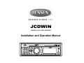
1
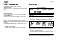
JCDWIN
MOBILE CD PLAYER / RECEIVER
Installation and Operation Manual
JCDWIN
SAFETY INFORMATION
DISC NOTES
When Driving
Compatible Disc Types
Keep the volume level Iow enough to be aware of your surroundings.
Table 1: General Disc Information
When Washing your Vehicle
Do not expose the product directly to water, as this can cause electrical shorts, fire or other
damage.
Disc Type
Diameter/
Playable Sides
Logo
When Parked
Audio CD
Exposure to direct sunlight for an extended period of time can produce very high temperatures
inside the mobile unit. Give the interior a chance to cool down before starting playback.
12 cm single side
RECORDABLE
Do not mount radio in close proximity of the engine compartment.
Playback Time
74 minutes
REWRITABLE
Use the Proper Power Supply
This product is designed to operate with a 12 volt DC negative ground battery system.
Protect the Disc Mechanism
NOTE: CD-R and CD-RW discs will not play unless the recording session is closed and
the CD is finalized.
Avoid inserting any foreign objects into the disc slot. Misuse may cause malfunction or
permanent damage due to the precise mechanism of this unit.
Disc Maintenance
CAUTION:
•
THIS MOBILE CD PLAYER IS A CLASS I LASER PRODUCT. THIS UNIT USES A VISIBLE/
INVISIBLE LASER BEAM WHICH COULD CAUSE HAZARDOUS RADIATION IF EXPOSED
DIRECTLY. BE SURE TO OPERATE THE MOBILE CD PLAYER AS INSTRUCTED.
A dirty or defective disc may cause sound dropouts while playing. Before playing, wipe
the disc using a clean cloth, working from the center hole towards the outside edge.
Never use benzene, thinners, cleaning fluids, anti-static liquids or any other solvent.
USE OF CONTROLS OR ADJUSTMENTS OR PERFORMANCE OR PROCEDURES OTHER
THAN THOSE SPECIFIED HEREIN MAY RESULT IN HAZARDOUS RADIATION
EXPOSURE.
DO NOT OPEN COVERS AND DO NOT REPAIR BY YOURSELF. PLEASE REFER
SERVICING TO A QUALIFIED TECHNICIAN.
Insert label
side up.
WARNING:
•
•
TO REDUCE THE RISK OF FIRE OR ELECTRIC SHOCK, DO NOT EXPOSE THIS
EQUIPMENT TO RAIN OR MOISTURE.
TO REDUCE THE RISK OF FIRE OR ELECTRIC SHOCK AND ANNOYING
INTERFERENCE, USE ONLY THE RECOMMENDED ACCESSORIES.
•
•
•
Do not bend.
Never touch
the under side
of the disc.
Wipe clean from
the center to the
edge.
Be sure to use only round CDs for this unit and do not use any special shape CDs. Use of
special shape CDs may cause the unit to malfunction.
Do not stick paper or tape on the disc. Do not use CDs with labels or stickers attached or
that have sticky residue from removed stickers.
Do not expose discs to direct sunlight or heat sources such as hot air-ducts, or leave them
in a vehicle parked in direct sunlight where there can be a considerable rise in
temperature inside the vehicle.
NOTE: A disc may become scratched (although not enough to make it unusable)
depending on how you handle it and other conditions in the usage environment. These
scratches are not an indication of a problem with the player.
2
JCDWIN
INSTALLATION
Before You Begin
1.
2.
7.
Disconnect Battery
Before you begin, always disconnect the battery negative terminal.
Remove Transport Screws
8.
Important Notes
•
•
•
•
•
•
•
•
Before final installation, test the wiring connections to make sure the unit is connected
properly and the system works.
Use only the parts included with the unit to ensure proper installation. The use of
unauthorized parts can cause malfunctions.
Consult with your nearest dealer if installation requires the drilling of holes or other
modifications to your vehicle.
Install the unit where it does not interfere with driving and cannot injure passengers if
there is a sudden or emergency stop.
If the installation angle exceeds 30º from horizontal, the unit might not give optimum
performance.
This unit is not waterproof and is intended for interior mounting applications only.
Exterior mounting of the unit requires use of an ASA approved marine housing.
Avoid installing the unit where it will be subject to high temperatures from direct sunlight,
hot air, or from a heater, or where it would be subject to excessive dust, dirt or vibration.
Be sure to remove the control panel before installing the unit.
9.
Removing the Unit
Mounting the Unit
To remove the radio after installation, insert the
removal keys straight back until they click, and
then pull the radio out. If removal keys are
inserted at an angle, they will not lock properly
to release the unit.
This unit can be property installed with a conventional DIN front mount.
1.
2.
3.
4.
5.
6.
problem is corrected. Once proper operation is achieved, turn the ignition switch off and
proceed with final mounting of the chassis.
Carefully slide the radio into the mounting sleeve making sure it is right-side-up until it is
fully seated and the spring clips lock it into place.
Attach one end of the
perforated support strap
Dashboard
(supplied) to the screw stud on
Support Strap
the rear of the chassis using
the hex nut and spring washer
Plain Washer
provided. Fasten the other end
Screw (5 x 25mm)
of the perforated strap to a
secure part of the dashboard
Screw Stud
Hex Nut (5mm)
either above or below the radio
using the screw and plain
Spring Washer
washer provided. Bend the
strap, as necessary, to position
it. CAUTION: The rear of the
radio must be supported with
the strap to prevent damage to
the dashboard from the weight
of the radio or improper operation due to vibration.
Test radio operation by referring to the operating instructions for the unit.
Slide the mounting sleeve off of the chasDashboard
sis if it has not already been removed. If it
Bend Tabs
is locked into position, use the removal
182
keys (supplied) to disengage it. The
removal keys are depicted in “Removing
53
the Unit” on page 3.
Screw Stud
Check the dashboard opening size by
sliding the mounting sleeve into it. If the
opening is not large enough, carefully cut
or file as necessary until the sleeve easily
slides into the opening. Do not force the
sleeve into the opening or cause it to bend
or bow. Check that there will be sufficient space behind the dashboard for the radio
chassis.
Locate the series of bend tabs along the top, bottom and sides of the mounting sleeve.
With the sleeve fully inserted into the dashboard opening, bend as many of the tabs
outward as necessary to firmly secure the sleeve to the dashboard.
Place the radio in front of the dashboard opening so the wiring can be brought through the
mounting sleeve.
Follow the wiring diagram carefully and make certain all connections are secure and
insulated with crimp connectors or electrical tape to ensure proper operation.
After completing the wiring connections, turn the unit on to confirm operation (vehicle
ignition switch must be on). If the unit does not operate, recheck all wiring until the
Reconnect the Battery
When wiring is complete, reconnect the battery
negative terminal.
3
Removal Key
JCDWIN
WIRING
15A FUSE
A-A
Wire Connector
ACCESSORY/IGNITION (+)
Connect to existing radio accessory fuse or
+12 VDC switched power source.
POWER ANTENNA
Connect to power antenna or amplifier. If not
used, tape bare end of wire.
MEMORY/BATTERY (+)
Connect to battery or 12 volt power source
that is always live. The radio will not work if
this wire is not connected.
GROUND
Connect to ground terminal or clean,
unpainted metal part of chassis.
4
A- A
SHOWN FROM PIN VIEW
JCDWIN
3.
BASIC OPERATION
Press MODE again to cancel Aux In mode and return to previous mode.
Reset
1
12
7
6
21
5
4
19
3
After releasing the control panel, use a pencil or any non-metallic object to press and hold the
RESET button (17) for five seconds to reset the main unit. The unit will return to the factory
default settings. The reset button should be activated for the following reasons:
2
•
•
•
9
17
initial installation of the unit when all wiring is completed
function buttons do not operate
error symbol on the display
Audio Menu
10
Press the AUDIO button (4) on the control panel (or the S button on the remote control) to
access the Audio Menu. You can navigate through the Audio Menu items by pressing the
AUDIO (or S) button repeatedly. Once the desired menu item appears on the display, adjust
that option by turning the AUDIO control (or pressing the VOL /\ or VOL \/ buttons (24) on the
remote control) the within 5 seconds. The unit will automatically exit the Audio Menu after five
seconds of inactivity. The following menu items can be adjusted.
13
11
14 15 22 16
8
18
20
Volume Level
Use the button to adjust the Volume level from “00” (lowest) to “100” (highest).
Power On/Off ( )
Press the
button (1) to turn the unit ON or OFF.
Volume Control
To increase the volume, turn the AUDIO control (4)
clockwise. To decrease the volume, turn the AUDIO
control counter-clockwise. If using the remote control,
press the VOL /\ or VOL \/ button (24) to adjust the
volume.
When the volume is adjusted, the volume level is
shown on the display panel as a number ranging from
00 (lowest) to 100 (highest).
Mute
Press the MUTE button (8) on the control panel (or the
MUT button on the remote control) to mute the audio
output. “Mute” will appear on the display. Press MUTE
again to restore the audio output to the previous level.
Bass Level
1
S
Use the button to adjust the Bass level range from “-10” to “+10”.
4
Treble Level
Use the button to adjust the Treble level range from “-10” to “+10”.
VOL
24
Balance
VOL
Use the button to adjust the Balance between the right and left speakers from “10L” (full left) to
“10R” (full right). “BAL L=R” represents an equal balance between the right and left speakers.
19
18
U
D
TR. DN
21
TR. UP
LOUD
BND
SCN
MOD
LOC
AMS
PEQ
15
9
12
13
Fader
5
Use the button to adjust the Fader between the rear and front speakers from “10R” (full rear) to
“10F” (full front). “FAD R=F” represents an equal balance between the front and rear speakers.
23
16
8
7
22
MUT
DISP
SCN
RPT
1
2
3
4
5
6
MO
PAU
SHUF
Loudness Control (LOUD)
6
11
When listening to music at low volume levels, this feature will boost the bass and treble ranges
to compensate for the characteristics of human hearing. Press and hold the BAND/LOUD
button (21) to activate this feature. “LOUD ON” appears on the display panel. Press the BAND/
LOUD button (21) again to turn the LOUD function off.
10
14
Audible Beep
Mode
To turn on/off the audible beep heard when a function is selected, press and hold the AUDIO
control button (4) on the control panel (or the S button on the remote control) to access the
Beep option. Within five seconds, turn the AUDIO control (4) to choose between the following
modes: “BEEP ALL”, “BEEP OFF”, or “BEEP 2ND”. Choose “BEEP 2ND” to hear a beep only
when secondary functions are activated (for example, functions accessed when you press and
hold a button).
Press the MODE button (5) on the control panel (or
the MOD button on the remote control) to select a
different mode of operation, as indicated on the display panel. Available modes include Radio,
CD, and AUX In (optional Auxiliary Input).
Auxiliary Input
1. Connect the external signal to the “Aux In” jack (20) located on the front of the control
panel. If you have a device connected to the rear auiliary input, the front auxiliary device
will override the rear one.
2. Press the MODE button to select Aux In mode.
5
JCDWIN
Display Selector (DISP)
TUNER OPERATION
This unit can display either the clock time or radio frequency/CD player functions. Press the
DISP button (6) on the control panel or remote control to display the time for approximately 5
seconds. The correct time of day can be set by pressing and holding the DISP button.
1
12
7
6
21
5
4
19
3
2
Setting the Clock
To set the clock, perform the following steps:
1.
2.
3.
4.
5.
Press the DISP button (6) to display the clock.
Press and hold the DISP button (6) until the time display flashes.
Within 5 seconds, press the TUNE down button (18) to adjust the minutes to the desired
setting.
Press the TUNE up button (19) to adjust the hour.
Press the DISP button again to return to radio frequency or disc play or wait five seconds
and normal operation will resume automatically.
9
17
10
13
11
Preset Equalizer (PEQ)
The preset equalizer applies preset sound effects to the unit’s audio output signal. To adjust
the preset equalizer, press the PEQ button (23) on the remote control. Press repeatedly to
choose between the following modes: “FLAT”, “CLASSICS”, “POP M”, “ROCK M” or “DSP
OFF”.
14 15 22 16
8
18
20
Select a Band
Press the BAND button (21) on the control panel (or BND on the remote control) to change
between three FM bands and one AM band. Each band stores up to six preset stations.
Tuning
Auto Seek Tuning
Press the TUNE up (19) or TUNE down button (18) on the control panel (or U and D on the
remote control) for less than three seconds to move to the next station automatically.
Manual Tuning
Press the TUNE up (19) or TUNE down button (18) for more than three seconds to enter
manual tuning mode. Press the TUNE up or TUNE down button to change the radio frequency
number up or down one step.
Scan
Press the SCAN button (22) on the control panel (or SCN on the remote control) to
automatically search for stations. Each available station will flash on the display for a few
seconds before the next is searched. To select a “flashing” station, press the SCAN button
again.
Preset Stations
Six numbered preset buttons store and recall stations for each band.
Store a Station
Select a band (if needed), then select a station. Hold a preset button (9-14) for three seconds.
The preset number will appear in the display.
Recall a Station
Select a band (if needed). Press a preset button (9-14) to select the corresponding stored
station.
6
JCDWIN
Automatically Store / Preset Scan (AS/PS, AMS)
CD OPERATION
Automatically Store
Select a band (if needed). Press the AS/PS button (16) on the control panel (or the AMS button
on the remote control) for more than three seconds to automatically select six strong stations
and store them in the current band. The new stations replace any stations already stored in
that band.
1
Preset Scan
12
7
6
21
5
4
19
3
2
9
Select a band (if needed). Press the AS/PS button (16) on the control panel (or the AMS button
on the remote control) to scan stations stored in the current band. The unit will pause for ten
seconds at each preset station. Press AS/PS again to stop scanning when the desired station
is reached.
10
FM Mono Select (MONO)
11
17
13
During FM radio operation, the MONO button (7) is used to select monaural or stereo reception
of the broadcast signal. Under normal reception conditions, the unit should be left in the stereo
mode (indicated by the “ST” icon when tuned to an FM stereo signal). If the signal is too noisy
for comfortable listening, press the MONO button on the control panel (or the MO button on the
remote control). To return to stereo reception mode, press the MONO button again.
14 15 22 16
8
18
20
Insert and Eject Disc
Insert a disc, label-side up, with the unit turned on. “CDP PLAY” will display on the LCD for
about 5 seconds and the unit will play the first track on the disc. Press the eject button (2) to
stop disc play and eject the disc. The unit does not have to be turned on to eject the disc.
Controlling Disc Playback
Track Select
Press the TUNE up button (19) or TUNE down button (18) on the control panel for less than
one second to advance to the next track on the CD. The selected track number will appear on
the display. Press and hold the TUNE up button (19) or TUNE down button (18) for >1 second
to fast forward or fast reverse through the disc. CD play starts when the button is released.
Play/Pause Disc Playback (1/>||)
Press the 1/>|| button (9) to suspend disc play. Press the 1/>|| button again to resume disc
Play.
Intro Scan (2/INT)
Press the 2/INT button (10) on the control panel to play the first 10 seconds of each track
sequentially. Press 2/INT again to stop Intro Scan and resume normal play at the current track.
Repeat Play (3/RPT)
Press the 3/RPT button (11) during disc play to repeat play the current track. Press 3/RPT
again to stop repeat play.
Random Play (4/SHF)
Press the 4/SHF button (12) on the control panel during disc play to play all tracks on a CD in
random, shuffled order. Press 4/SHF again to stop random play.
7
JCDWIN
SPECIFICATIONS
TROUBLESHOOTING
CD
S/N Ratio. . . . . . . . . . . . . . . . . . . . . . . . . . . . . . . . . . . . . . . . . . . . . . . . . . . . . . . . . . . > 70dB
Sampling Frequency . . . . . . . . . . . . . . . . . . . . . . . . . . . . . . . . . . . . . . . . . . . . . . . . . 44.1Khz
Quantization Bits . . . . . . . . . . . . . . . . . . . . . . . . . . . . . . . . . . . . . . . . . . . . . . . . . . . . . . . .1 bit
Frequency Response . . . . . . . . . . . . . . . . . . . . . . . . . . . . . . . . . . . . . . . . . . . . . 5-20,000Hz
Symptom
No power
Cause
Solution
The vehicle’s power is not
on
If the power supply is properly
connected to the vehicle accessory terminal, switch the ignition
key to “ACC”.
The fuse is blown
Replace the fuse.
Presence of CD disc inside
the player
Remove the disc in the player and
insert the new one.
AM/MW
Frequency Range . . . . . . . . . . . . . . . . . . . . . . . . . . . . . . . . . . . . . . . . . . . . . . . 530-1710KHz
Usable Sensitivity . . . . . . . . . . . . . . . . . . . . . . . . . . . . . . . . . . . . . . . . . . . . . . . . . . . . > 45dB
S/N Ratio. . . . . . . . . . . . . . . . . . . . . . . . . . . . . . . . . . . . . . . . . . . . . . . . . . . . . . . . . . . . . 40dB
Inserting the disc upside
down
Insert the compact disc with the
label facing upward.
Compact disc is extremely
dirty or disc is defective
Clean the disc or try to play a new
one.
General
Operating Voltage . . . . . . . . . . . . . . . . . . . . . . . . . . . . . . . . . . . . . . . . . . . . . . . DC 11 -14.4V
Grounding System . . . . . . . . . . . . . . . . . . . . . . . . . . . . . . . . . . . . . . . . . . . Negative Ground
Speaker Impedance . . . . . . . . . . . . . . . . . . . . . . . . . . . . . . . . . . . . . . . . . . . . . . . . . . 4 ohms
Power Output . . . . . . . . . . . . . . . . . . . . . . . . . . . . . . . . . . . . . . . . . . . . . . . . . . . . . . 40W x 4
Temperature inside the
vehicle is too high
Wait until the ambient temperature returns to normal.
Condensation
Leave the player off for an hour or
so, then try again.
Volume too low or Mute is
on
Adjust volume to audible level.
Fader is set incorrectly
Press AUDIO button to access
menu and adjust FADER setting/
Wiring is not properly connected
Check wiring connections.
Unit is unresponsive
The built-in microcomputer
is not operating properly
Press the RESET button.
Sound skips
The installation angle is
more than 30 degrees
Adjust the installation angle to
less than 30 degrees.
The disc is dirty or defective
Clean the disc and try to play
again or use new disc.
Cannot tune to radio station, auto-seek does not
work
The antenna cable is not
connected
Insert the antenna cable firmly.
The signals are too weak
Select a station manually.
ERROR 1
Mechanism Error
Press the eject button to correct
the problem.
If the error code does not disappear, consult your nearest service dealer.
ERROR 2
Servo Error
Press the eject button to correct
the problem.
If the error code does not disappear, consult your nearest service dealer.
FM Radio
Frequency Range . . . . . . . . . . . . . . . . . . . . . . . . . . . . . . . . . . . . . . . . . . . . . . 87.5-107.9MHz
Usable Sensitivity . . . . . . . . . . . . . . . . . . . . . . . . . . . . . . . . . . . . . . . . . . > 15dB at S/N 30dB
Stereo Separation . . . . . . . . . . . . . . . . . . . . . . . . . . . . . . . . . . . . . . . . . . . . . . . 25dB at 1KHz
S/N Ratio. . . . . . . . . . . . . . . . . . . . . . . . . . . . . . . . . . . . . . . . . . . . . . . . . . . . . . . . . . . . . 50dB
Disc cannot be loaded or
ejected
No sound
8
JCDWIN
9
ASA Electronics Corporation
www.asaelectronics.com
www.jensenrvdirect.com
© 2009 ASA Electronics Corporation
v. 012909