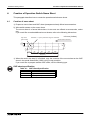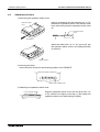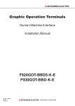
1
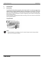
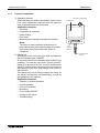
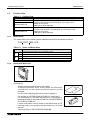
MITSUBISHI ELECTRIC
GOT series
Human-Machine-Interface
Hardware Manual
Handy Graphic Operation Terminal
F940GOT
Art.No.: 132728
2001 05 07
JY992D86901-B
MITSUBISHI ELECTRIC INDUSTRIAL AUTOMATION
Foreword
• This manual contains text, diagrams and explanations which will guide the reader in the
correct installation and operation of the F940GOT Handy Series. It should be read and
understood before attempting to install or use the unit.
• Further information can be found in the GOT-F900 Series Operation Manual, GOT-900
Series Hardware Manual and manual of the associated PLC.
• If in doubt at any stage of the installation of F940GOT Handy Series always consult a
professional electrical engineer who is qualified and trained to the local and national
standards which apply to the installation site.
• If in doubt about the operation or use of F940GOT Handy Series please consult the nearest
Mitsubishi Electric distributor.
• This manual is subject to change without notice.
F940GOT Handy Series
F940GOT Handy Series
(F94*GOT-*BD-H-E)
Hardware Manual
Manual number : JY992D86901
Manual revision : B
Date
: March 2001
i
F940GOT Handy Series
ii
F940GOT Handy Series
FAX BACK
Mitsubishi has a world wide reputation for its efforts in continually developing and pushing back
the frontiers of industrial automation. What is sometimes overlooked by the user is the care
and attention to detail that is taken with the documentation. However,to continue this process
of improvement, the comments of the Mitsubishi users are always welcomed. This page has
been designed for you,the reader,to fill in your comments and fax them back to us. We look
forward to hearing from you.
Fax numbers:
Your name ....................................................
Mitsubishi Electric....
.....................................................................
America
(01) 847-478-2283
Your company ..............................................
Australia
(02) 638 -7072
.....................................................................
Germany
(0 21 02) 4 86-1 12
Your location:................................................
South Africa
(0 27) 11 444-0223
.....................................................................
United Kingdom
(01707) 278-695
Please tick the box of your choice
¨Minor damage
¨Unusable
Will you be using a folder to store the manual?
¨Yes
¨No
What do you think to the manual presentation?
¨Tidy
¨Unfriendly
¨Not too bad
¨Unusable
What condition did the manual arrive in?
Are the explanations understandable?
¨Good
¨Yes
Which explanation was most difficult to understand: ..................................................................
....................................................................................................................................................
¨Yes
Are there any diagrams which are not clear?
¨No
If so,which: ..................................................................................................................................
What do you think to the manual layout?
¨Good
¨Not too bad
¨Unhelpful
If there one thing you would like to see improved,what is it? ......................................................
....................................................................................................................................................
....................................................................................................................................................
Could you find the information you required easily using the index and/or the contents,if possible please identify your experience:............................................................................................
....................................................................................................................................................
....................................................................................................................................................
....................................................................................................................................................
....................................................................................................................................................
Do you have any comments in general about the Mitsubishi manuals? .....................................
....................................................................................................................................................
....................................................................................................................................................
....................................................................................................................................................
....................................................................................................................................................
Thank you for taking the time to fill out this questionnaire. We hope you found both the product
and this manual easy to use.
iii
F940GOT Handy Series
iv
F940GOT Handy Series
Guidelines for the Safety of the User and Protection of the F940GOT Handy
Series (F94*GOT-*BD-H-E)
This manual provides information for the use of the F940GOT Handy Series. The manual has
been written to be used by trained and competent personnel. The definition of such a person
or persons is as follows;
a) Any engineer who is responsible for the planning, design and construction of automatic
equipment using the product associated with this manual should be of a competent
nature, trained and qualified to the local and national standards required to fulfill that
role. These engineers should be fully aware of all aspects of safety with regards to
automated equipment.
b) Any commissioning or service engineer must be of a competent nature, trained and
qualified to the local and national standards required to fulfill that job. These engineers
should also be trained in the use and maintenance of the completed product. This
includes being completely familiar with all associated documentation for the said product.
All maintenance should be carried out in accordance with established safety practices.
c) All operators of the completed equipment should be trained to use that product in a safe
and co-ordinated manner in compliance to established safety practices. The operators
should also be familiar with documentation which is related to the actual operation of the
completed equipment.
Note : Note: the term ‘completed equipment’ refers to a third party constructed device which
contains or uses the product associated with this manual.
Notes on the Symbols Used in this Manual
At various times through out this manual certain symbols will be used to highlight points of
information which are intended to ensure the users personal safety and protect the integrity of
equipment. Whenever any of the following symbols are encountered its associated note must
be read and understood. Each of the symbols used will now be listed with a brief description of
its meaning.
Hardware Warnings
1) Indicates that the identified danger WILL cause physical and property damage.
2) Indicates that the identified danger could POSSIBLY cause physical and property
damage.
3) Indicates a point of further interest or further explanation.
Software Warnings
4) Indicates special care must be taken when using this element of software.
5) Indicates a special point which the user of the associate software element should
be aware of.
6) Indicates a point of interest or further explanation.
v
F940GOT Handy Series
• Under no circumstances will Mitsubishi Electric be liable or responsible for any
consequential damage that may arise as a result of the installation or use of this equipment.
• All examples and diagrams shown in this manual are intended only as an aid to
understanding the text, not to guarantee operation. Mitsubishi Electric will accept no
responsibility for actual use of the product based on these illustrative examples.
• Owing to the very great variety in possible applications of this equipment, you must satisfy
yourself as to its suitability for your specific application.
vi
F940GOT Handy Series
Table of Contents
Guideline for Safty................................................................................v
Associated Manual Lists.......................................................................... ix
1. Introduction............................................................................................1-1
1.1 Introduction .......................................................................................................... 1-1
1.1.1 Product Components................................................................................................. 1-2
1.2 Product Lists ........................................................................................................ 1-3
1.2.1 Model Name .............................................................................................................. 1-3
1.2.2 Handy GOT Main Unit ............................................................................................... 1-3
1.3 Options ................................................................................................................ 1-4
1.3.1 External Cable ........................................................................................................... 1-4
1.3.2 Other Options ............................................................................................................ 1-4
1.3.3 Spare Parts ............................................................................................................... 1-6
1.4 Dimensions and Each Part Name ....................................................................... 1-7
1.4.1 Each Part Name of Front Panel and Dimensions...................................................... 1-7
1.4.2 Rear face ................................................................................................................... 1-8
2. Specifications ........................................................................................2-1
2.1
2.2
2.3
2.4
General Specifications......................................................................................... 2-2
Power Supply Specifications ............................................................................... 2-2
Screen Hardware Specifications ......................................................................... 2-3
Emergency and Operation Switch Specifications ................................................ 2-3
3. Installation and Wiring ...........................................................................3-1
3.1 Installation Method .............................................................................................. 3-1
3.1.1 Holding ...................................................................................................................... 3-1
3.1.2 Wall Mounting............................................................................................................ 3-2
3.1.3 Flat Surface Mounting ............................................................................................... 3-2
3.2 Connection Configuration .................................................................................... 3-3
3.2.1 Connection to PLC by F940GOT-*BD-H-E (RS-422) ................................................ 3-3
3.2.2 Connection to PLC by F943GOT-*BD-H-E (RS-232C) ............................................. 3-4
3.2.3 Signal Allocation of Connector and Untied Wires...................................................... 3-5
3.3 Installation of External Cable ............................................................................... 3-6
3.4 Processing Panel of Control Box or Cabinet ....................................................... 3-8
3.4.1
3.4.2
3.4.3
3.4.4
Using F940GOT Handy ............................................................................................. 3-8
Using F943GOT Handy ........................................................................................... 3-10
Appearance of Relay Cable .................................................................................... 3-11
Mounting Connector of Relay Cable ....................................................................... 3-12
3.5 Wiring of Power Supply ..................................................................................... 3-13
4. Creation of Operation Switch Name Sheet ...........................................4-1
4.1 Creation of name sheet ....................................................................................... 4-1
4.2 Attachment of sheet............................................................................................. 4-2
5. Maintenance ..........................................................................................5-1
5.1 Replacement of battery ....................................................................................... 5-1
vii
F940GOT Handy Series
6. Diagnostics ............................................................................................6-1
6.1 Primly Check ....................................................................................................... 6-1
6.2 Check Error Messages ........................................................................................ 6-1
viii
F940GOT Handy Series
Associated Manual Lists
Associated Manual Lists
Further information can be found in the following manuals.
Manual Title
Manual Number
Description
¤
GOT-F900 Series
Operation Manual
JY992D94701
This manual contains explanations for the
operation and use of the GOT-F900 series
graphic operation terminals.
¤
GOT-F900 Series
Hardware Manual
JY992D94801
This manual contains explanations for the wiring
and installation, etc. of the GOT-F900 series
graphic operation terminals.
¡
FX-PCS-DU/WIN-E
Operation Manual
JY992D68301
This manual contains explanations for the
operation of FX-PCS-DU/WIN-E screen design
software.
¡
SW*D5C-GOTR-PACKE
Operating Manual
o
F9GT-HCNB
Hardware Manual
JY992D88901
This manual contains explanations for the
operation of GT-Designer (SW*D5C-GOTRPACKE) screen design software.
This manual contains explanations for installation
an wiring of F9GT-HCNB Hardware Manual.
¤: Indispensable manual
¡: Either manual is necessary.
o: Refer if necessary, please.
ix
F940GOT Handy Series
Associated Manual Lists
MEMO
x
F940GOT Handy Series
1
Introduction
2
Specifications
3
Installation and Wiring
4
Creation of Operation Switch Name Sheet
5
Maintenance
6
Diagnostics
Introduction 1
F940GOT Handy Series
Introduction 1
F940GOT Handy Series
1.
Introduction
1.1
Introduction
Introduction 1
The F940GOT Handy Series (hereafter called “Handy GOT”) is an all-in-one type handy
graphic operation terminal equipped with a touch key display unit (F94*GOT-*WD-E) and
mechanical keys (operation switches) available for command input to the machine. The Handy
GOT can connect to MELSEC FX, A, QnA and Q PLCs as well as a host of third party manufactured units. Further information of system configuration can be found in the GOT-F900
Series Hardware Manual.
Further information regarding optional cables connecting a PLC can be found in the GOT-F900
Series Hardware Manual.
Using Example
Note;
Screens displayed on the display unit can be created using the screen design software
which runs on a personal computer.
1-1
F940GOT Handy Series
1.1.1
Introduction 1
Product Components
1) Operation switches
These switches give direct commands to inputs on the
PLC, when immediate response from the machine
such as operation and stop is required.
Application examples:
• Start/stop
• Preparation for operation
• Setup change
• Error reset
• Mode selection between automatic and manual
E m e r g e n c y s to p s w itc h
D is p la y u n it
P O W E R
G R IP S W
Note;
The name of these operation switches can be
personalized using a transparent sheet and a name
base sheet offered as accessories. (Refer to
Chapter 4)
2) Display unit
The display unit is touch-key type LCD equivalent to
that of a standard type F940GOT.
All functions offered in the standard type F940GOT are
available. The operator can easily monitor ON/OFF
status of bit devices in the PLC, set such bit devices to
ON/OFF, monitor the set value and the current value of
word devices of the PLC, and change such values of
word devices.
This display unit can be used to change the setup, or
set values, and perform troubleshooting, as well as
give guidance to the operator.
Application examples:
• Selection of manual operation
• manual operation
• One-cycle operation
• Monitoring
• Force turning ON/OFF
• Change of set values
• Troubleshooting
O p e r a tio n
s w itc h e s
E x te r n a l c a b le
( o p tio n )
1-2
F940GOT Handy Series
1.2
Introduction 1
Product Lists
Table 1.1: Product Lists
Production Name
F940GOT-SBD-H-E
Handy GOT main unit
This type uses RS-422 communication for connecting to PLC.
- SBD type is 8 Colors
- LBD type is White and black
F940GOT-LBD-H-E
F943GOT-SBD-H-E
Handy GOT main unit
This type uses RS-232C communication for connecting to PLC.
- SBD type is 8 Colors
- LBD type is White and black
F943GOT-LBD-H-E
1.2.1
Description
Model Name
The model name of the handy graphic operation terminal is expressed as follows.
F 9 4* G OT-* B D -H -E
A
B
Table 1.2: Notes on Model Name
Description
A
B
1.2.2
0
RS-422 communication for connecting to PLC
3
RS-232C communication for connecting to PLC
S
STN type 8 colors liquid crystal
L
STN type black and white liquid crystal
Handy GOT Main Unit
PO
WE
R
GR
IP
SW
Accessories:
- Sheets to change switch names (All model)
A transparent sheet and a mount sheet are offered as
accessories so that operation switch names can be
changed.
For the name changing procedure, refer to chapter 4.
- Ferrite filter for CE EMC (F943GOT-*BD-H-E model only)
For compliance to CE EMC regulations it is necessary to
add a ferrite filter on the external cable for F943GOT-SBD-HE or F943GOT-LBD-H-E.
Further information can be found in the Notification of CE
marking sheet in the product box and section 3.2.2 of this
manual.
This ferrite filter is TDK ZCAT2035-0930A-BK.
1-3
F940GOT Handy Series
1.3
Options
1.3.1
External Cable
Introduction 1
These external cable containing independent wires for communications, DC power supply,
operation switches and the emergency switch. One of those wired below is always necessary.
Table 1.3: External Cable
Model Name
F9GT-HCAB-3M
F9GT-HCAB-10M
F9GT-HCAB1-3M
F9GT-HCAB1-10M
Description
25-pin D-sub connector on one side,
- 3M: Cable length is 3m (9' 10")
- 10M: Cable length is 10m (32' 9")
United wires on one side,
- 3M: Cable length is 3m (9' 10")
- 10M: Cable length is 10m (32' 9")
F o r 2 5 p in
D -s u b
F o r u n ite d w ir e s
Note;
When using F9GT-HCAB-*M external cable, one of the following relay cables or an F9GTHCNB conversion box is necessary.
1.3.2
Other Options
Order the following options upon necessity.
1) Relay cable for PLC
• F9GT-HCAB2-150
This cable connects an FX 0 /FX 0S /FX 0N /FX 1S /FX 1N /FX 2N /
FX2NC (with 8-pin MINI-DIN connector), and is equipped with
an external cable (with 25-pin D-sub connector) for power
supply, operation switch and emergency switch.
Cable length is 1.5 m (4' 11").
To PLC
For power supply or
operation switch
Note;
This cable cannot be used for the F943GOT-*BD-H-E (RS-232C communication type
Handy GOT).
• F9GT-HCAB3-150
This cable connects an FX/FX 2C /A/QnA Series PLC or
motion controller (with 25-pin D-sub connector), and is
equipped with an exter nal cable (with 25-pin D-sub
c o nn e c to r ) fo r p owe r s u p p ly, o p era tio n sw it ch a n d
emergency switch
Cable length is 1.5 m (4' 11").
To PLC
For power supply or
operation switch
Note;
This cable cannot be used for the F943GOT-*BD-H-E (RS-232C communication type
Handy GOT).
1-4
F940GOT Handy Series
• F9GT-HCAB5-150
This cable connects a Q Series PLC or motion controller
(with 6-pin MINI-DIN connector), and is equipped with an
external cable (with 25-pin D-sub connector) for power
supply, operation switch and emergency switch
Cable length is 1.5 m (4' 11").
Introduction 1
To PLC
For power supply or
operation switch
Note;
This cable cannot be used for the F940GOT-*BD-H-E (RS-422 communication type
Handy GOT).
2) F9GT-HCNB conversion box
This box converts a 25-pin D-sub connector of an external cable
into a port for PLC connection and separate terminals for power
supply, operation switch and emergency switch.
Note;
This conversion box cannot be used for the F943GOT-*BD-H-E (RS-232C
communication type Handy GOT).
3) Communication cables
• FX-40DU-CAB
This cable connects the F9GT-HCNB and CPU por t
(programming port) on an FX/FX2C/A Series PLC by CPU
port connection setting.
Cable length is 3.0 m (9' 10")
This cable is not available when a Handy GOT is connected
by way of a communication port (communication unit).
Further information can be found in the GOT-F900 Series
Hardware Manual.
• FX-50DU-CAB0 /-1M
Either of these cables connects the F9GT-HCNB and an FX0/
FX0S/FX0N/FX1S/FX1N/FX2N/FX2NC Series PLC by CPU port
connection setting.
Cable length;
- Normal type: 3m (9' 10")
- -1M type: 1m (3' 3")
4) Protective sheets F9GT-40PSC (5 sheets in 1 set)
Adhere one disposable sheet to the display screen for protection
against dirt and abrasion.
1-5
F940GOT Handy Series
Introduction 1
5) Screen design software
Table 1.4: Screen Design Software
Model Name
Description
FX-PCS-DU/WIN-E
SW0PC-FXDU/WIN-E Version V2.10 or more
(3.5 FD)
GT-Designer
SW1D5C-GOTR-PACKE Version 40E or more
(CD-ROM)
6) FX-2PIF two-port interface
This interface offered as an option allows use of a Handy GOT
and a peripheral unit for creating programs at the same time.
This interface is not available when the Handy GOT is
connected to a general-purpose personal computer or when the
Handy GOT is connected by way of a computer link unit.
Note;
This unit cannot be used for the F943GOT-*BD-H-E (RS-232C communication type
Handy GOT).
1.3.3
Spare Parts
1) FX2NC-32BL Battery
This battery is used to back up the alarm history, sampling and
the current time data.
For replacement, refer to chapter 5.
1-6
F940GOT Handy Series
Introduction 1
1.4
Dimensions and Each Part Name
1.4.1
Each Part Name of Front Panel and Dimensions
Dimensions: mm (inches)
MASS: 0.79 kg (1.74 lbs)
1 5 6 (6 .1 4 ")
a )
b )
5 0 .5
(1 .9 9 ")
1 3 (0 .5 1 ")
W h e n th e o p e r a tio n s w itc h c o v e r is r e m o v e d
1 7 2
1 9 1
f )
g )
P O W E R
P O W E R
G R IP S W
G R IP S W
O p e r a tio n s w itc h c o v e r
e )
d )
c )
a) Touch key LCD unit
This display unit offers the functions equivalent to those offered by the display unit of the
standard type F940GOT series. Further information of standard type F940GOT series
can be found in the GOT-F900 Series Operation Manual.
b) Emergency stop switch
Independent contact, 24V DC specification.
c) Grip switch LED
Lit while the grip switch provided on the side is being pressed.
d) Operation switches
Direct connection to inputs in the PLC.
The name of these operation switches can be personalized using a transparent sheet
and a name base sheet offered as accessories. (Refer to Chapter 4)
Each of these switches is equipped with a green LED which indicates its status. The
green LED lighting command is transferred between the PLC through serial
communication.
These LEDs can be controlled by user program in PLC. Further information can be found
in the GOT-F900 Series Hardware Manual.
e) POWER LED
Lit while 24V DC power is supplied to the Handy GOT.
f) Grip switch
A grip switch is provided on the side of the Handy GOT. While the grip switch is being
pressed, manipulation of the touch keys on the screen is effective. Further information
can be found in the GOT-F900 Series Hardware Manual.
g) Operation switch name sheet insertion slot
Can be seen when the operation switch cover is removed from the lower portion of the
Handy GOT.
1-7
F940GOT Handy Series
1.4.2
Introduction 1
Rear face
W h e n th e r e a r c o v e r is r e m o v e d
( e n la r g e d v ie w )
c )
a )
c )
d )
e )
b )
N o t u s e d
f )
a) Metal hook for wall mounting
Offered to mount the Handy GOT on a wall.
b) Hand strap
Adjustable length strap allowing comfortable holding of the Handy GOT.
c) Port for communications signal, the DC power supply, the operation switches and the
emergency switch
d) FX2NC-32BL Battery
Built in to back up data.
For replacement, refer to chapter 5.
e) Port for personal computer (9-pin D-sub, male) (for RS-232C communication)
Offered to transfer screen data created using the screen design software or use the
two-port interface function.
f) External cable
Offered to connect a PLC, power supply or operation switch to ports outlined in “c)”.
1-8
F940GOT Handy Series
1
Introduction
2
Specifications
3
Installation and Wiring
4
Creation of Operation Switch Name Sheet
5
Maintenance
6
Diagnostics
Specifications 2
F940GOT Handy Series
Specifications 2
F940GOT Handy Series
2.
Specifications 2
Specifications
Caution
During abnormal communication (including cable break) when monitor is executed within
the Handy GOT, communication between the Handy GOT and programmable controller
CPU is interrupted and it is impossible to operate switches or devices in the PLC through
the Handy GOT.
Communication and operation resumes when the Handy GOT system is correctly
configured.
DO NOT configure emergency stop or safety features to operate through the Handy GOT,
and be sure that there is no adverse consequences in the event of a Handy GOT - PLC
communications malfunction.
Note;
• Do not lay signal cables near high voltage power cables or allow them to share the same
trunking duct.
Otherwise effects of noise or surge induction are likely to take please. Keep a safe
distance of more than 100 mm from these wires.
• Operate touch switches on the display screen by hand.
DO NOT use excessive force, or attempt operate them with hard or pointed objects.
The tip of a screw driver, pen or similar object for example may break the screen.
2-1
F940GOT Handy Series
2.1
Specifications 2
General Specifications
Table 2.1:
General Specifications
Item
2.2
Specifications
Operating Temperature
0 ~ 40 °C (32 ~ 104 °F)
Storage Temperature
-20 ~ 60 °C (-4 ~ 140 °F)
Humidity
35 ~ 85% Relative Humidity, No condensation
Vibration Resistance
- intermittent vibration
Conforms to IEC 1131-2; 10 ~ 57 Hz: 0.075 mm Half Amplitude
57 ~ 150 Hz: 9.8 m/s2 Acceleration
Sweep Count for X, Y, Z: 10 times (80 min. in each direction)
Vibration Resistance
- Continuous vibration
Conforms to IEC 1131-2; 10 ~ 57 Hz: 0.035 mm Half Amplitude
57 ~ 150 Hz: 4.9 m/s2 Acceleration
Sweep Count for X, Y, Z: 10 times (80 min. in each direction)
Shock Resistance
Conforms to IEC 1131-2: 147m/s2 Acceleration,
3 times in each direction X, Y, and Z
Noise Immunity
1000 Vp-p, 1micro second, 30 ~ 100 Hz, tested by noise simulator
Dielectric Withstand
Voltage
500 V AC > 1 min., tested between power terminals and ground
Insulation Resistance
5 MΩ > at 500 V DC, tested between power terminals and ground
Ground
Grounding register 100 Ω or less (Class D)
Protection
IP 54
Power Supply Specifications
Table 2.2:
Power Supply Specifications
Items
Specifications
Power Supply Voltage
24V DC, +10% -15%
Power Supply Ripple
200 mV or less
Current Consumption
Ratings: 300 mA at 24V DC
(200 mA at 24V DC when backlight is turned OFF)
Fuse
Fuse 1.0 A built-in Handy GOT (impossible to change)
Max. Allowable
Momentary Power
Supply Failure period
5 ms; If less than 5 ms, the Handy GOT will continue operation. If 5 ms or
more, the Handy GOT will shut down.
Battery
Built-in, FX2NC-32BL type lithium battery. (Approximately 3 years life)
Guaranteed term is 1 year.
2-2
F940GOT Handy Series
2.3
Specifications 2
Screen Hardware Specifications
Table 2.3:
Screen Hardware Specifications
Items
F94*GOT-LWD-E
Display Device
STN color liquid crystal
Resolution
320 × 240 (dot), 40 characters × 15 lines
Dot Pitch
0.36 mm (0.014") Horizontal × 0.36 mm (0.014") Vertical.
Effective Display Size
115 mm (4.53") × 86 mm (3.39"); 6 (5.7 inch) type
Number of Colors
8 colors
Life of liquid crystal
Approximately 50,000 hours (Operating temperature: 25 ×°C / 77×°F)
Guaranteed term is 1 year.
Backlight
Cold cathode tube
Life of Backlight
40,000 hours or more (Operating temperature: 25 ×°C / 77×°F)
Guaranteed term is 1 year.
Touch Keys
Maximum 50 touch keys / screen, 20 × 12 matrix
Interface
2.4
F94*GOT-SWD-E
With PLC
F940GOT-*DB-H-E: RS-422
F943GOT-*DB-H-E: RS-232C
With
personal
computer
Conforming to RS-232C
White and Black
Number of Screens
User screen: 500 screens or less
System screen: Allocated screens No. 1001-1030.
User Memory
Flash memory 512 KB (built-in)
Emergency and Operation Switch Specifications
Table 2.4:
Emergency and Operation Switch Specifications
Item
Description
Operation switch
a-contact × 4 points, 10 mA/24V DC
(Operation life time: appraxinately1,000,000 times)
Emergency stop switch
b-contact × 1 point, 1 A/24V DC, independent wiring
(AH165-VR01 manufactured by Fuji Electric)
2-3
F940GOT Handy Series
Specifications 2
MEMO
2-4
Handy GOT Handy Series
Installation and Wiring 3
1
Introduction
2
Specifications
3
Installation and Wiring
4
Creation of Operation Switch Name Sheet
5
Maintenance
6
Diagnostics
Handy GOT Handy Series
Installation and Wiring 3
Handy GOT Handy Series
3.
Installation and Wiring 3
Installation and Wiring
This section describes installation of the Handy GOT and wiring of the power supply and the
operation switches.
Thoroughly understand the specifications before performing installation and wiring.
3.1
Installation Method
Note;
• Do not mount the GOT in an environment that contains dust, soot corrosive or conducive
dust, corrosive or flammable gas, or expose the unit to high temperatures, dew
condensation, rain and wind or impact and vibration.
If the GOT is used in such a place, electrical shock, fire, malfunction, damage or
deterioration may be caused.
• Make sure that the power is turned off, before securely connecting any cables. Poor
connection may cause malfunction.
3.1.1
Holding
When holding the Handy GOT for operation, place your hand through the hand strap provided
on its rear face. You can adjust the length of the hand strap.
Hand strap
3-1
Handy GOT Handy Series
3.1.2
Installation and Wiring 3
Wall Mounting
When mounting the Handy GOT on a wall, use the metal hook provided on its rear face.
M e ta l h o o k fo r m o u n tin g o n w a ll
W a ll fa c e
φ5 m m
(0 .2 0 ")
φ1 0 m m ( 0 . 3 9 " )
F la t h e a d s c r e w
M 3 x 6 m m
On the wall face, the weight of the main unit (approximately 0.79 kg/1.74 lbs) and a load of
approximately 1 ~ 3 kg (2.20 ~ 6.61 lbs) which varies depending on the communication cable
length are applied. While taking this into consideration, attach a suitable metal fixture on the
wall.
3.1.3
Flat Surface Mounting
When using the Handy GOT on a flat surface, such as a desk or shelf, keep the Handy GOT
parallel to the surface so that it does not drop and, fix the communication cable to the desk.
P O
W E
R
G R
IP
S W
It is r e c o m m e n d e d to fix
th e e x te r n a l c a b le .
3-2
Handy GOT Handy Series
Installation and Wiring 3
3.2
Connection Configuration
3.2.1
Connection to PLC by F940GOT-*BD-H-E (RS-422)
Connection of Handy GOT (F940GOT-*BD-H-E) to PLC is shown below. Further information
regarding applicable PLCs can be found in GOT-F900 Series Hardware Manual.
Further information can be found
in subsection 3.2.3.
F940GOT Handy
a)
c)
To the FXseries PLC
(8-pin MINI-DIN connector)
For power supply and
operation switches
PO
WER
a)
GR
IP
d)
SW
To the FX
(25-pin D-sub connector),
A and QnA series PLC
For power supply and
operation switches
Further information can be found
in subsection 3.2.3.
Connect the cable to
the port on the rear
face.
e)
a)
f)
To the FXseries PLC
(8-pin MINI-DIN connector)
For power supply and
operation switches
g)
To the FX
(25-pin D-sub connector),
A and QnA series PLC
b)
Further information can be
found in subsection 3.2.3.
To the communication unit of
the A, QnA and Q series, or
host of third party
manafactured units. And power
supply and operation swiches.
a) External cable (with 25-pin D-sub connector on one side)
F9GT-HCAB-3M (3m/9' 10"), F9GT-HCAB-10M (10m/32' 9")
b) External cable (with untied 20-core wires on one side)
F9GT-HCAB1-3M (3m/9' 10"), F9GT-HCAB1-10M (10m/32' 9")
c) Relay cable for PLC connection (with 8-pin MINI-DIN connector on PLC side)
F9GT-HCAB2-150 (1.5m/4' 11")
d) Relay cable for PLC connection (with 25-pin D-sub connector on PLC side)
F9GT-HCAB3-150 (1.5m/4' 11")
e) Conversion box F9GT-HCNB
Further information can be found in F9GT-HCNB Hardware Manual
f) PLC connection cable (with 8-pin MINI-DIN connector on PLC side)
FX-50DU-CAB0 (3m/9' 10"), FX-50DU-CAB0-1M (1m/3' 3")
g) PLC connection cable (with 25-pin D-sub connector on PLC side)
FX-40DU-CAB (3m/9' 10")
3-3
Handy GOT Handy Series
3.2.2
Installation and Wiring 3
Connection to PLC by F943GOT-*BD-H-E (RS-232C)
Connection of the Handy GOT (F943GOT-*BD-H-E) to a PLC is shown below.
Further information regarding applicable PLCs can be found in GOT-F900 Series Hardware
Manual.
Further information can be
found in subsection 3.2.3.
a)
c)
To Q series PLC
(6-pin MINI-DIN connector)
For power supply and operation
switches
Further information can be
found in subsection 3.2.3.
PO
WER
GR
IP
SW
a)
d)
Connect the cable
to the port on the
rear face.
To the communication unit of
the A, QnA and Q series or host
of third party manufactured
units. And operetion swiches
and power supply
b)
Further information can be
found in subsection 3.2.3.
To the communication unit of
the A, QnA and Q series or host
of third party manufactured
units. And operetion swiches
and power supply
a) External cable (with 25-pin D-sub on one side)
F9GT-HCAB-3M (3m/9' 10")
b) External cable (with untied 20-core wires on one side)
F9GT-HCAB1-3M (3m/9' 10")
c) Relay cable (with 6-pin MINI-DIN on one side)
F9GT-HCAB5-150 (1.5m/4' 11")
d) Cable prepared by user
Note:
The connection distance between the handy graphic operation terminal and the PLC (“a) +
c)” or “a) + b)”) should be within 6 m (19' 8").
Caution for CE EMC:
For compliance to CE EMC regulations it is necessary to add
a ferrite filter on the external cable for F943GOT-SBD-H-E or
F943GOT-LBD-H-E.
The filter should be attached as shown right with the filter
surrounding the external cable.
The recommended ferrite filter is the TDK ZCAT2035-0930ABK or equivalent.
P O W E R
G R IP S W
1 0 0 m m
( 3 .9 3 " o r le s s )
F e r r ite filte r
3-4
Handy GOT Handy Series
3.2.3
Installation and Wiring 3
Signal Allocation of Connector and Untied Wires
The signal allocation within connector and untied wires of an external cable are shown below.
United wires (20-core)
25-pin D-sub, male connector
••• •••
1
13
Distingushed
by color
14
25
Table 3.1: Name of communication, power supply and operation switches
External Cable
Pin No.
(F9GTHCAB-*M)
Signal Name
Color of
United wires F940GOT Handy F943GOT Handy
(F9GT(RS-422)
(RS-232C)
HCAB1-*M)
FG (shield)
Description
1
Drain wire
Frame ground
2
Black
TXD+ (SDA)
SD (TXD)
3
White
TXD- (SDB)
ER (DTR)
4
Red
RTS+ (RSA)
RD (RXD)
5
Green
RTS- (RSB)
DR (DSR)
6
Yellow
RXD+ (RDA)
RS (RTS)
7
Brown
RXD- (RDB)
CS (CTS)
8
Blue
CTS+ (CSA)
NC
9
Gray
CTS- (SCB)
NC
10
Orange
SG
Signal ground
11
-
NC
Not used
12
Purple
13
Pink
14
Note 1
DC 24V G
24V DC power supply “-”
Light green
SW-COM
COM for Operation switches
15
Sky blue
SW1
16
Black/white
SW2
17
Red/white
SW3
18
Green/white
SW4
19
-
20
-
21
Brown/white
ES1
22
Yellow/white
ES1
23
-
NC
24
Blue/white
25
Gray/white
NC
DC 24V +
Operation switches
Not used
Emergency stop switch
Not used
24V DC power supply “+”
Note 1;
These are signals for communication with the PLC. When connecting to a port other than
the programming port of the FX, A, QnA or Q series PLC, refer to the manual of the
connected module. Also use a relay cable. For relay cable details, refer to subsection 1.3.2.
3-5
Handy GOT Handy Series
3.3
Installation and Wiring 3
Installation of External Cable
Connect an optional external cable to the Handy GOT main unit.
Table 3.2: External Cable
Model Name
Length
F9GT-HCAB-3M
F9GT-HCAB-10M
Description
3m (9' 10")
*1
10m (32' 9")
F9GT-HCAB1-3M
3m (32' 9")
F9GT-HCAB1-10M*1
10m (9' 10")
25-pin D-sub connector on one side
Untied 20-core wires on one side
*1 The cable cannot be used for the F943GOT Handy type (RS-232C communication type
Handy GOT).
1) Remove rear cover
Remove the mounting screws “a)”, and open the rear cover.
b )
c )
e )
d )
N o te
a )
a) Rear cover mounting screws, (M3 × 8mm, 4 screws)
b) Packing seal
c) Mounting slot
d) Connector for communication or power switch (20-pin type)
e) Power connector (8-pin type)
Note;
• Never remove any screw (among seven screws located around the rear face of the
Handy GOT) other than the mounting screws “a)”.
If such a screw is removed, the waterproof ability may deteriorate or failure may occur.
• When installing rear cover, securely tighten mounting screws with a torque of 0.49 ~ 0.68
N m if tightened more than this, the cover may crack, and the water and dustproof
properlies may be lost.
• Before closing the rear cover, make sure that the packing “b)” has not come off.
3-6
Handy GOT Handy Series
Installation and Wiring 3
2) Put the external cable through the hole “c)” in the Handy GOT main unit, and connect it to
“e)” and “d)”.
W h e n p u s h in g th e c a b le th r o u g h ,
m a k e e a c h c o n n e c to r fa c e d o w n w a rd .
3) Tighten the hexagon nut.
P a c k in g
H e x a g o n n u t fo r
c a b le m o u n tin g
H e x a g o n n u t
fo r c a b le s e c o r in g
2 2 m m
Make sure to tighten the hexagon nut for cable
mounting with a sufficient force to avoid
looseness.
As guideline, tighten it until the packing is
crushed by 0.5 mm (0.02") or more.
(0 .8 7 ")
4) Pull lightly on the cable until it naturally stops.
P u llin g d ir e c tio n
5) Securely tighten the hexagon nut for cable sewring so that the cable will not come out or the
waterproof ability will not be deteriorated.
N o te
Note;
As guideline, make sure that clearance is 3.5 mm (0.14") or less.
3-7
Handy GOT Handy Series
Installation and Wiring 3
3.4
Processing Panel of Control Box or Cabinet
3.4.1
Using F940GOT Handy
1) Installing a connector on the panel of control box or cabinet.
Connect an FX/A/QnA Series PLC using a relay cable for connection to PLC as shown
below. Further information re applicable PLCs can be found in GOT-F900 Series Hardware
Manual.
C o n tro l p a n e l o r
o p e r a tio n p a n e l
F 9 4 0 G O T H a n d y
P O W E R
G R IP S W
P L C
b )
a )
a) External cable (with 25-pin D-sub male connector)
Table 3.3: External Cable
Model Name
Length
F9GT-HCAB-3M
3m (9' 10")
F9GT-HCAB-10M
10m (32' 9")
b) Relay cable for connection to PLC
Table 3.4: Relay Cable
Model Name
F9GT-HCAB2-150
F9GT-HCAB3-150
Length
1.5m (4' 11")
Applicable
FX Series (FX0, FX0S, FX0N, FX1S, FX1N, FX2N, FX2NC)
FX (FX, FX2C), A, QnA Series
Note;
When connecting to a port or unit other than the programming port of an FX, A or QnA
series PLC, make a cable corresponding to the cofiguration of the communications port in
question. Or use F9GT-HCAB1-**M external cable. For allocation of Handy GOT
communication signals, refer to subsection 3.2.3.
3-8
Handy GOT Handy Series
Installation and Wiring 3
2) Using F9GT-HCNB
Connect an FX/A/QnA Series PLC using a F9GT-HCNB as shown below. Fur ther
information about the installing F9GT-HCNB can be found in F9GT-HCNB Hardware
Manual.
F 9 4 0 G O T H a n d y
P a n e l fa c e o f c o n tro l
b o x o r c a b in e t
P o w e r s u p p ly a n d
o p e r a tio n s w itc h e s
P O W E R
G R IP S W
P L C
b )
a )
c )
a) External cable (with 25-pin D-sub male connector)
Table 3.5: External Cable
Model Name
Length
F9GT-HCAB-3M
3m (9' 10")
F9GT-HCAB-10M
10m (32' 9")
b) F9GT-HCNB conversion box
c) Communication cable for connection to PLC
Table 3.6: Communication Cable
Model Name
Length
Applicable
FX-50DU-CAB0
3m (9' 10")
FX-50DU-CAB0-1M
1m (3' 3")
FX Series (FX0, FX0S, FX0N, FX1S, FX1N, FX2N,
FX2NC)
FX-40DU-CAB
3m (9' 10")
FX (FX, FX2C), A, QnA Series
3-9
Handy GOT Handy Series
3.4.2
Installation and Wiring 3
Using F943GOT Handy
Installing a connector on the panel of control box or cabinet
Connect a Q Series PLC using a relay cable for connection to PLC as shown below. Connect
an FX/A/QnA Series PLC using a F9GT-HCAB1-**M external cable for connection to these
PLC. Further information about applicable PLC can be found in GOT-F900 Series Hardware
Manual.
F 9 4 3 G O T H a n d y
P O W E R
G R IP S W
C o n to r o l b o x o r c a b in e t
b )
P L C
a )
a) External cable (with 25-pin D-sub male connector)
F9GT-HCAB-3M (3m /9' 10")
b) Relay cable for connection to Q series PLC
F9GT-HCAB5-150 (1.5m /4' 11") for Q series PLC
Note;
When connecting to a port or unit other than the programming port of an FX, A or QnA
series PLC, make a cable corresponding to the cofiguration of the communications port in
question. Or use F9GT-HCAB1-**M external cable. For allocation of Handy GOT
communication signals, refer to subsection 3.2.3.
3-10
Handy GOT Handy Series
3.4.3
Installation and Wiring 3
Appearance of Relay Cable
Table 3.7:
Model Name
F9GT-HCAB2-150
F9GT-HCAB3-150
Length
Applicable
FX Series (FX0, FX0S, FX0N, FX1S, FX1N, FX2N, FX2NC)
1.5m (4' 11")
FX (FX, FX2C), A, QnA Series
1) F9GT-HCAB2-150 relay cable for FX Series (FX0, FX0S, FX0N, FX1S, FX1N, FX2N, FX2NC)
PLC
1 .5 m
(4 ' 1 1 ")
T o p o w e r s u p p ly a n d o p e r a tio n s w itc h e s .
A n a m e la b e l is a tta c h e d to th e tip o f e a c h
u n tie d w ir e .
C o n n e c te d
e x te rn a l
c a b le
T o F X s e r ie s P L C ( 8 - p in M IN I- D IN c o n n e c to r )
2 5
c o
(p
m
p in
n n e
a n e
o u n
D - s u b fe m a le
c to r
l fa c e
tin g ty p e )
0 .5 m
(1 ' 7 ")
F o r g ro u n d
( g r o u n d in g r e s is ta n c e 1 0 0 Ωo r le s s , c la s s D )
2) F9GT-HCAB3-150 relay cable for FX (FX, FX2C), A, QnA series PLC
1 .5 m
(4 ' 1 1 ")
T o p o w e r s u p p ly a n d o p e r a tio n s w itc h e s .
A n a m e la b e l is a tta c h e d to th e tip o f e a c h
u n tie d w ir e .
C o n n e c te d
e x te rn a l
c a b le
2 5
c o
(p
m
p in
n n e
a n e
o u n
D - s u b fe m a le
c to r
l fa c e
tin g ty p e )
T o F X ( 2 5 p in D - s u b c o n n e c to r ) , A a n d Q n A
s e r ie s P L C
0 .5 m
(1 ' 7 ")
F o r g ro u n d
( g r o u n d in g r e s is ta n c e 1 0 0 Ωo r le s s , c la s s D )
3) F9GT-HCAB5-150 relay cable for Q series PLC
1 .5 m
(4 ' 1 1 ")
T o p o w e r s u p p ly a n d o p e r a tio n s w itc h e s .
A n a m e la b e l is a tta c h e d to th e tip o f e a c h
u n tie d w ir e .
C o n n e c te d
e x te rn a l
c a b le
T o Q
2 5
c o
(p
m
p in
n n e
a n e
o u n
D - s u b fe m a le
c to r
l fa c e
tin g ty p e )
0 .5 m
s e r ie s P L C ( 6 - p in M IN I- D IN c o n n e c to r )
(1 ' 7 ")
F o r g ro u n d
( g r o u n d in g r e s is ta n c e 1 0 0 Ωo r le s s , c la s s D )
3-11
Handy GOT Handy Series
3.4.4
Installation and Wiring 3
Mounting Connector of Relay Cable
When mounting the relay cable connector on the panel of a control box or cabinet, prepare
panel of control box or cabinet as follows.
Panel cut size
47.04 (1.85")
2-φ3.2±0.1
(0.13"±0.004")
42.5 (1.67") or more
indicates the cut area.
11.4 (0.45") or more
Unit: mm (inches)
4-R3.4 (0.13")
10°
(Panel thickness: 0.8 ~ 1.3mm / 0.03" ~ 0.05")
Insert a jack socket into a hole shown above, and tighten it with a nut (M3).
M 2 .6
Jack socket
4 .8
(0 .1 9 ")
M 3
Connected to
external
connection cable
Panel face on
which cable
is mounted
J a c k s o c k e t
Nut (M3)
Cable side
3-12
Handy GOT Handy Series
3.5
Installation and Wiring 3
Wiring of Power Supply
Further information about operation switches and emergency switch can be found in GOTF900 Series Hardware Manual.
Caution:
Cut OFF all phases of power source externally, before installation or wiring work in order to
avoid electric shock or damage to the product.
Note:
• Insure correct termination of DC power source, incorrect connection may result in unit
failure or the GOT being burnt.
• Attach a fuse of 2 A to the 24V DC power supply.
• Perform Class D grounding to the Handy GOT (grounding register 100Ω or less).
Never perform common grounding of the GOT and a strong power system.
Note
• Feed power to the GOT by an external power supply.
(The service power supply of the programmable controller cannot be used.)
• Even if instantaneous power interruption of less than 5 ms occurs, the GOT continues its
operation. When power interruption for considerable period of time or voltage drop
occurs, the GOT stops its operation. However, when the power supply is recovered, the
GOT automatically restarts its operation. (The screen displayed just after recovery is
determined by the working environment originally set.)
3-13
Handy GOT Handy Series
Installation and Wiring 3
Handy GOT power is supplied from the PLC or an external power supply unit.
The current consumption of the Handy GOT is 300 mA at 24V DC. (Refer to section 2.2.)
Grounding resistance
100Ω or less (class D)
Grounding resistance 24V DC external
100Ω or less (class D) power supply
Fuse (2A)
FG 24VG 24V+
Handy GOT
PLC
Communication cable
Note;
When the input power for the PLC main unit is equivalent to the input power for the external
power supply, grounding may be performed by connecting the frame ground of the Handy
GOT to the ground terminal of the PLC.
When the input power is different (PLC: 100V AC, external power supply: 200V AC), perform
dedicated grounding to each of the PLC and Handy GOT.
External
power
supply unit
PLC
Handy GOT
Grounding resistance
100Ω or less (class D)
200V AC
100V AC
PLC
External
power
supply unit
Grounding resistance
100Ω or less (class D)
Handy GOT
Grounding resistance
100Ω or less (class D)
Table 3.8: Allocation of Signal 24V+ / 24VG /FG
External Cable
F9GT-HCAB-*M
(Pin No.)
F9GT-HCAB1-*M
(Pin No.)
F9GT-HCNB
Conversion Box
(Terminal Name)
24V+
24, 25
Blue/white, Gray/white
DC24V +
24VG
12, 13
Purple, Pink
DC24V -
1
Drain wire
FG
Signal Name
in Diagram
FG
3-14
F940GOT Handy Series
Creation of Operation Switch Name Sheet 4
1
Introduction
2
Specifications
3
Installation and Wiring
4
Creation of Operation Switch Name Sheet
5
Maintenance
6
Diagnostics
F940GOT Handy Series
Creation of Operation Switch Name Sheet 4
F940GOT Handy Series
4.
Creation of Operation Switch Name Sheet 4
Creation of Operation Switch Name Sheet
This paragraph describes how to create the operation switch name sheet.
Creation of name sheet
1) Prepare a mount sheet and OHP sheet (transparent sheet) offered as accessories.
2) Write switch names on the mount sheet.
The mount sheet is of actual dimensions. As two sets are offered as accessories, select
one.
If you would like to make additional mount sheets, refer to the following dimensions.
unit: mm (inches)
-0 .0 4 "
0 .7 9
+ 0
2 0
C
+ 0
D ia m e te r = 1 7 ( 0 .6 7 " ) : E ffe c tiv e r a n g e fo r c h a r a c te r s
S h e e t in s e r tio n d ir e c tio n
-1
K e y c e n te r
( p r in t c e n te r )
1 0
(0 .3 9 ")
4.1
2
1 2
(0 .4 7 )
2 2
(0 .8 7 ")
2 2
(0 .8 7 ")
9 6 (3 .7 8 ")
2 2
(0 .8 7 ")
(1 8 )
(0 .7 1 ")
1) When the work in the step 2) is finished, copy the contents of the mount sheet on the OHP
sheet in the actual dimensions (100%) using a copy machine.
If you would like to prepare another OHP sheet, use the following type.
OHP sheet specification
Table 4.1: OHP Sheet Specification
Item
Specifications
Material
Polyester film
Thickness
0.1 mm (0.004")
4-1
F940GOT Handy Series
4.2
Creation of Operation Switch Name Sheet 4
Attachment of sheet
1) Removing the operation switch cover
O p e r a tio n s w itc h
c o v e r
Insert a screwdriver into the clearance “a)” or “b)”
between the operation switch cover and the main
body, and slowly push the operation switch cover
up.
b )
a )
O p e r a tio n s w itc h
c o v e r
c )
S c r e w d r iv e r
When the either side “a)” or “b)” comes off, pull
the operation switch cover in the sliding direction
to remove it.
b )
a )
c )
S lid in g d ir e c tio n
2) Inserting the sheet
Insert the name sheet into the following position of the F940GOT.
Name sheet insertion slot
3) Attaching the operation switch cover
L e t it b e s lig h tly w a r p e d .
a )
b )
Align the operation switch cover with the protrusion “a)”
or “b)” shown in the figure in the step 1), then attach the
operation switch cover while flexing it slightly.
4-2
F940GOT Handy Series
1
Introduction
2
Specifications
3
Installation and Wiring
4
Creation of Operation Switch Name Sheet
5
Maintenance
6
Diagnostics
Maintenance 5
F940GOT Handy Series
Maintenance 5
F940GOT Handy Series
5.
Maintenance 5
Maintenance
Cautions:
• Correctly install the battery for memory backup. Never charge, disassemble, heat, burn
or short-circuit the battery. If the battery is handled in such a way, bursting or fire may be
caused.
• Always power OFF and remove the Handy GOT from any mounting location before
starting replacement of the backlight and battery. If this is not the case, the backlight may
be dropped and cause injury, or electrical shock may be sustained.
• Never disassemble or modify the Handy GOT. Disassembly or modification may cause
failure, malfunction or fire. For repair, please, contact a service representative.
Note:
Make sure to turn OFF the power, before connecting/disconnecting cables.
If you connect/disconnect cables while the power is turned on, failure or malfunction may be
caused.
5.1
Replacement of battery
When the battery voltage drops, a control device (system information) set by the screen design
software turns ON. The control device interlocks with an auxiliary relay in the PLC. It is recommended to provide a lamp while utilizing the output of the PLC so that voltage drop can be
monitored outside the handy GOT.
For details of control devices, refer to the GOT-F900 Series Operation Manual.
Note:
For approximately one month after the control device for battery voltage drop turns ON, the
battery backs up the alarm history, sampling and the current time. When the control device
(system information) turns ON, replace the battery (FX2NC-32BL) soon.
The screen data is stored in the flash memory. Even if the battery is totally worn out, the
screen data remains stored
F X
2 N C
-3 2 B L
1) Turn off the power of the Handy GOT.
2) Open the small window of the rear panel.
3) Remove the existing battery from the holder, and disconnect it.
4) Within 30 seconds, connect a new battery.
5) Insert the new battery into the holder, and close the
small window.
5-1
F940GOT Handy Series
Maintenance 5
MEMO
5-2
F940GOT Handy Series
1
Introduction
2
Specifications
3
Installation and Wiring
4
Creation of Operation Switch Name Sheet
5
Maintenance
6
Diagnostics
Diagnostics 6
F940GOT Handy Series
Diagnostics 6
F940GOT Handy Series
6.
Diagnostics
6.1
Primly Check
Diagnostics 6
1) Check “POWER LED”
If the POWER LED is OFF, check cable(s), and check 24V DC power souce capacity is sufficient.
2) Check display
If the display screen is dark, adjust “LCD CONTRAST” in “SET-UP MODE”.
If the display screen remains dark even after adjustment, it is recommended to replace the
backlight. In this case, please contact a service representative.
3) Check setting “PLC TYPE” in “SET-UP MODE”
If this setting is incorrect, Handy GOT cannot communicate with the PLC correctly.
6.2
Check Error Messages
The table below shows the list of error messages displayed during manipulation or operation.
Check the contents, and take proper action.
Table 6.1: Check Error Massages
Error message
Description
Action
CAN NOT WRITE
PLC MEMORY.
The PLC is running in EPROM mode.
Or the write-protect switch of the
EEPROM is set to ON.
Run the PLC in RAM mode. Or set
OFF the write-protect switch of the
EEPROM.
PLC IS RUNNING.
A program is trying to be written from a
personal computer using “DATA
Stop the PLC. Or enter the correct
TRANSFER” in “OTHER MODE” while
entry code.
the PLC is running. Or an entry code
has been registered.
DATA IS NOT
FOUND.
There are no screen data or data files.
Create the data using the screen creation software.
DISPLAY SCREEN
IS NOT AVAILABLE.
Screen No. 0 (in the case of FX-PCSDU/WIN-E) or screen No. 1 (in the
case of DT-Designer) is not created
yet.
When a screen is to be changed over,
there is no destination screen.
Create screen No. 0 or 1.
Or change the changeover destination
screen, or create the corresponding
screen.
6-1
F940GOT Handy Series
Diagnostics 6
MEMO
6-2
F940GOT Handy Series
Diagnostics 6
MEMO
6-3
F940GOT Handy Series
Diagnostics 6
MEMO
6-4
MITSUBISHI ELECTRIC
Headquarters
European Representatives
EUROPE
MITSUBISHI ELECTRIC EUROPE B.V.
Gothaer Str. 8
D-40880 Ratingen
GERMANY
Phone: +49 (0) 2102/486-0
Fax:
+49 (0) 2102/486-112
ITALY
MITSUBISHI ELECTRIC EUROPE B.V.
C.D. Colleoni - P. Perseo Ing. 2, Via Paracelso 12
I-20041 Agrate Brianza (MI)
ITALY
Phone: +39 (0)39 60 53 1
Fax:
+39 (0) 39 60 53 312
SPAIN
MITSUBISHI ELECTRIC EUROPE B.V.
Carretera de Rubi 76-80
E-08190 Sant Cugat del Vallés (Barcelona)
SPAIN
Phone: +34 9 3/565 31 31
Fax:
+34 9 3/589 29 48
UK
MITSUBISHI ELECTRIC EUROPE B.V.
Travellers Lane
GB-Hatfield Herts. AL10 8 XB
UK
Phone: +44 (0) 1707/27 61 00
Fax:
+44 (0) 1707/27 86 95
JAPAN
MITSUBISHI ELECTRIC CORPORATION
Mitsubishi Denki Bldg., 2-2-3 Marunouchi
Tokyo 100-8310
JAPAN
Phone: +81 (0) 3/32 18 31 76
Fax:
+81 (0) 3/32 18 24 22
USA
MITSUBISHI ELECTRIC AUTOMATION INC.
500, Corporate Woods Parkway
Vernon Hills, Illinois 60061
USA
Phone: +1 (0) 847/478 21 00
Fax:
+1 (0) 847 / 478 22 83
GEVA
Wiener Straße 89
A-2500 Baden
Phone: +43 (0) 2252 / 85 55 20
Fax:
+43 (0) 2252 / 488 60
AUSTRIA
Beijer Electronics AS
Teglverksveien 1
N-3002 Drammen
Phone: +47 32 / 24 30 00
Fax:
+47 32 / 84 85 77
N.V. GETRONICS Belgium S.A.
Pontbeeklaan 43
B-1731 Asse-Zellik
Phone: +32 (0) 2 / 467 17 51
Fax:
+32 (0) 2 / 467 17 45
BELGIUM
MPL Technology Sp. z o.o.
ul. Wroclawska 53
PL-30-011 Kraków
Phone: +48 (0) 12 / 632 28 85
Fax:
+48 (0) 12 / 632 47 82
TELECON CO.
4, A. Ljapchev Blvd.
BG-1756 Sofia
Phone: +359 2 97 44 05 8
Fax:
+359 2 97 44 06 1
BULGARIA
NORWAY
POLAND
ROMANIA
Sirius Trading & Services srl
Bd. Ghica nr. 112, Bl. 41, Sc.2, ap. 98
RO-72235 Bucuresti 2
Phone: +40 (0) 1 / 210 55 11
Fax:
+40 (0) 1 / 210 55 11
INEA CR d.o.o.
Drvinje 63
HR-10000 Zagreb
Phone: +385 (0) 1 / 366 71 40
Fax:
+385 (0) 1 / 366 71 40
CROATIA
Mitsubishi Electric Europe B.V.
12/1 Goncharnaya St, suite 3C
RUS-109240 Moscow
Phone: +7 (0) 95 / 915-8624/02
Fax:
+7 (0) 95 / 915-8603
RUSSIA
AutoCont Control Systems s.r.o.
Nemocnicni 12
CZ-702 00 Ostrava 2
Phone: +420 (0) 69 / 615 21 11
Fax:
+420 (0) 69 / 615 21 12
CZECHIA
NPP Uralelektra
Sverdlova 11A
RU-620027 Ekaterinburg
Phone: +7 (34 32) 53 27 45
Fax:
+7 (34 32) 53 24 61
RUSSIA
louis poulsen
Geminivej 32
DK-2670 Greve
Phone: +45 (0) 43 / 95 95 95
Fax:
+45 (0) 43 / 95 95 91
DENMARK
ACP AUTOCOMP a.s.
Chalupkova 7
SK-81109 Bratislava
Phone: +421 (0) 7 592 2248
Fax:
+421 (0) 7 592 2254
SLOVAKIA
UTU ELEKTROTEHNIKA AS
Pärnu mnt.160i
EE-11317 Tallinn
Phone: +372 6 / 51 72 80
Fax:
+372 6 / 51 72 88
ESTONIA
INEA d.o.o.
Ljubljanska 80
SI-1230 Domzale
Phone: +386 (0) 17 21 80 00
Fax:
+386 (0) 17 24 16 72
SLOVENIA
Beijer Electronics OY
Elannontie 5
FIN-01510 Vantaa
Phone: +358 (0) 9 / 615 20 11
Fax:
+358 (0) 9 / 615 20 500
FINLAND
Beijer Electronics AB
Box 325
S-20123 Malmö
Phone: +46 (0) 40 / 35 86 00
Fax:
+46 (0) 40 / 93 23 01
SWEDEN
IP Systèmes
8, Rue du Colonel Chambonnet
F-69672 Lyon Bron Cedex
Phone: +33 (0) 4 / 72 14 18 00
Fax:
+33 (0) 4 / 72 14 18 01
FRANCE
ECONOTEC AG
Postfach 282
CH-8309 Nürensdorf
Phone: +41 (0) 1 / 838 48 11
Fax:
+41 (0) 1 / 838 48 12
SWITZERLAND
MITSUBISHI ELECTRIC EUROPE B.V
Westgate Business Park, Ballymount
IRL-Dublin 24
Phone: +353 (0) 1 / 419 88 00
Fax:
+353 (0) 1 / 419 88 90
IRELAND
ILAN & GAVISH Automation Service
24 Shenkar St., Qiryat-Arie 49513
IL-49001 Petach-Tikva
Phone: +972 (0) 3 / 922 18 24
Fax:
+972 (0) 3 / 972 39 24 07 61
ISRAEL
TEXEL Electronics Ltd.
P.O. Box 6272
IL-42160 Netanya
Phone: +972 (0) 9 / 863 08 91
Fax:
+972 (0) 9 / 885 24 30
ISRAEL
GTS
Darülaceze Cad. No. 43A KAT: 2
TR-80270 Okmeydani-Istanbul
Phone: +90 (0) 212 / 320 1640
Fax:
+90 (0) 212 / 320 1649
TURKEY
UKRAINE
JV-CSC Automation
15, M. Raskovoyi St., Floor 10, Office 1010
U-02002 Kiev
Phone: +380 (4) 4 / 238 83 16
Fax:
+380 (4) 4 / 238 83 17
Getronics Industrial Automation B.V. NETHERLANDS
Donauweg 10
NL-1043 AJ Amsterdam
Phone: +31 (0) 20 / 586 15 92
Fax:
+31 (0) 20 / 586 19 27
7.5.2001
MITSUBISHI ELECTRIC INDUSTRIAL AUTOMATION
Gothaer Straße 8 Phone: +49 2102 486-0
Fax:
+49 2102 486-717
www.mitsubishi-automation.de
D-40880 Ratingen Hotline: +49 1805 000-766/765 Faxback: +49 2102 486-485/790 [email protected]
PLC - Printed in Germany