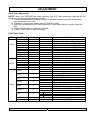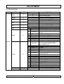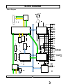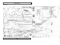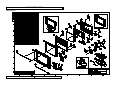
1
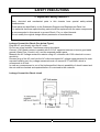
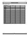
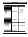
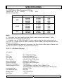
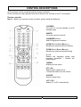
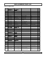
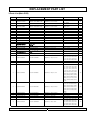
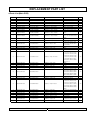
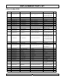
COLOR TFT-LCD TV
SERVICE MANUAL
MODEL : RL-20S10
CAUTION !!
BEFORE SERVICING THE TFT-LCD TV,
READ THE SAFETY PRECAUTIONS IN THIS MANUAL.
RL-20S10 SERVICE MANUAL
PAGE:1
CONTENTS
Contents ------------------------------------------------------------------------ 2
Safety Precautions ---------------------------------------------------------- 3
Servicing Precautions ------------------------------------------------------ 4
Specifications ----------------------------------------------------------------- 5
Control Descriptions -------------------------------------------------------- 9
External In/Out Ports ------------------------------------------------------- 12
Adjustment -------------------------------------------------------------------- 13
Block Diagram ---------------------------------------------------------------- 17
Schematic Diagram --------------------------------------------------------- 18
Wave Form --------------------------------------------------------------------- 19
Troubleshooting -------------------------------------------------------------- 25
Replacement Parts List ---------------------------------------------------- 29
PCB Layout -------------------------------------------------------------------- 37
Exploded View ---------------------------------------------------------------- 43
RL-20S10 SERVICE MANUAL
PAGE:2
SAFETY PRECAUTIONS
!! Important Safety Notice !!
Many electrical and mechanical parts in this chassis have special safety-related
characteristics.
These parts are identified by in the Schematic Diagram and Replacement Parts List.
It is essential that these special safety parts should be replaced with the same components
as recommended in this manual to prevent Shock, Fire, or other Hazards.
Do not modify the original design without permission of manufacturer.
Leakage Current Hot Check (See below Figure)
Plug the AC cord directly into the AC outlet.
Do not use a line Isolation Transformer during this check.
Connect 1.5K/10watt resistor in parallel with a 0.15uF capacitor between a known good earth
ground (Water Pipe, Conduit, etc.) and the exposed metallic parts.
Measure the AC voltage across the resistor using AC voltmeter with 1000 ohms/volt or more
sensitivity.
Reverse plug of the AC cord into the AC outlet and repeat AC voltage measurements for each
exposed metallic part. Any voltage measured must not exceed 0.75 volt RMS, which is,
corresponds to 0.5mA.
In case any measurement is out of the limits specified, there is possibility of shock hazard and
the set must be checked and repaired before it is returned to the customer.
Leakage Current Hot Check circuit
RL-20S10 SERVICE MANUAL
PAGE:3
SERVICING PRECAUTIONS
CAUTION!!
Before servicing receivers covered by this service manual, read and follow the SAFETY
PRECAUTIONS on page 3 of this publication.
General Servicing Precautions
1.Always unplug the receiver AC power cord from AC power source before;
ⓐRemoving or reinstalling any component, circuit board module or any other receiver assembly.
ⓑDisconnecting or reconnecting any receiver electrical plug or other electrical connection.
ⓒConnecting a test substitute in parallel with an electrolytic capacitor in the receiver.
CAUTION!! A wrong part substitution or incorrect polarity installation of electrolytic capacitors
may result in an explosion harzard.
2.Do not spray chemicals on or near this receiver or any of its assemblies.
3.Do not defect any plug/socket voltage interlocks with which receivers covered by this service
manual might be equipped.
4.Always connect the test receiver ground lead to the receiver chassis ground before
connecting the test receiver positive lead. Always remove the test receiver ground lead last.
5.Do not connect the test fixture ground strap to power supply heatsink in this receiver
Electrostatically Sensitive(ES) Devices
Some semiconductor(solid state) devices can be damaged easily by static electricity. Such
components commonly are called Electrostatically Sensitive(ES) Device.Examples
Circuit Board Foil Repair
Excessive heat applied to the copper foil of any printed circuit board will weaken the adhesive
that bonds the foil to the circuit board causing the foil th separate from or “lift-off” the board.
The following guidelines and procedures should be flollowed whenever this condition is
encountered.
At IC Connections
To repair a defective copper pattern at IC connections use the following procedure to install a
jumper wire on the copper pattern side of the circuit board.(Use this technique only on IC
connections.)
1.Carefully remove the damaged copper pattern with a sharp knife.(Remove only as much
copper as absolutely necessary.)
2.Carefully scratch away the solder resist and acrylic coating(if used) from the end of the
remaining coopper pattern.
3.Bend a small “U” in one end of a small guage jumper wire and carefully crimp it around the IC
pin.
4.Route the jumper wire along the path of the out-away copper pattern and let it overlap the
previously scraped end of the good copper pattern. Solder the overlapped area and clip off any
excess jumper wire.
RL-20S10 SERVICE MANUAL
PAGE:4
SPECIFICATIONS
Note: Specifications and others are subject to change without notice for improvement.
1.Scope.
This document is the specification of 20.1” TFT-LCD Color TV.
2.Power
1) Power requirement
DC 15V / 4.5A
2)AC / DC Adapter.
Input Frequency : 50/60㎐ ±3㎐
Input Voltage : AC 100V ~ AC 230V (±10%)
Output Voltage : DC 15V
3)Power cord
Use UL listed and CSA certified detachable power cord type ;SVT, 3-conductors, 18AWG
For AC 120V area. Use VDE listed detachable power cord type ;HO5VV-F, 3-conductors,
18AWG for AC 220~240V area.
3.Tuning system
FVS 100
4.Sound output
3W+3Wrms Stereo (Max)
5.Antenna input impedance
VHF / UHF at 75ohm
6.OSD Type (On Screen Display)
Windows type (Center)
7.External in/output
PC/DTV,SCART, Head Phone, S-Video, AV,
Audio In : 0.4Vrms, over 10KΩ
Video In : 1Vp-p, over 75Ω
PC/DTV In: 0.7Vp, over 75Ω
8.Function
CATV/Hyper band
Auto Program
Manual Program
Auto Sleep
Quick view
PSM(Picture Status memory)
SSM(Sound Status memory)
RL-20S10 SERVICE MANUAL
PAGE:5
SPECIFICATIONS
9.Receiving RF TV system
NO
1
2
3
4
5
6
7
8
9
10
11
12
13
14
15
16
17
18
19
20
21
22
23
24
25
26
Model System
PAL-B
PAL-G
PAL-I, I /I
PAL-D
PAL-K
SECAM-B
SECAM-G
SECAM-D
SECAM-K
SECAM-K1
SECAM-I (6.0)
NTSC-3.58 / 4.5
NTSC-3.58 / 5.5
NTSC-3.58 / 6.0
NTSC-3.58 / 6.5
NTSC-3.58 / 4.5(5.0)
NTSC-4.43 / 5.5
NTSC-4.43 / 6.0
NTSC-4.43 / 6.5
PAL 5.5 / 60Hz
PAL 6.0 / 60Hz
PAL 6.5 / 60Hz
SECAM 5.5 / 60Hz
SECAM 6.0 / 60Hz
SECAM 6.5 / 60Hz
SECAM L / L'
TOTAL SYSTEM
RL-20S10
/
/
○
○
○
○
○
○
○
○
○
○
○
○
○
○
○
○
○
○
○
○
○
○
○
○
○
X
25
/
/
/
/
/
/
/
/
/
/
/
/
/
/
/
/
/
/
/
/
/
/
/
/
/
/
/
/
/
/
/
/
/
/
/
/
/
/
/
/
/
/
/
/
/
/
/
/
/
/
/
/
/
/
RL-20S10 SERVICE MANUAL
PAGE:6
SPECIFICATIONS
10.Receiving function & Programme
NO
Receiving System
1
PAL-B
2
PAL-G
3
PAL- I, I / I
4
PAL-D
5
PAL-K
6
SECAM-B
7
SECAM-G
8
SECAM-D
9
SECAM-K
Function
Reception of broadcast
and play-back for Video
Tape Recorder
Receiving Channel
VHF Band
NTSC-M (US) : 2-13
NTSC-M (JAPAN) : 1-12
UHF Band
NTSC-M (US) : 14-78
NTSC-M (JAPAN) : 13-62
10 SECAM-K1
11 NTSC-M
12 SECAM-L / L'
13 NTSC-4.43 / 5.5
14 NTSC-4.43 / 6.0
15 NTSC-4.43 / 6.5
Play-back for special
Video Tape Recorder
NTSC 3.58/4.5MHz/60Hz only
Play-back for special
Video Tape/Video disk
player
NTSC 3.58/4.5MHz/60Hz only
16 SECAM-I (6.0MHz)
17 SECAM-L (VIDEO IN)
18 NTSC 3.58 / 4.5MHz / 50Hz
19 PAL 5.5MHz / 60Hz
20 PAL 6.0MHz / 60Hz
21 PAL 6.5MHz / 60Hz
22 SECAM 5.5MHz/60Hz
23 SECAM 6.0MHz/60Hz
24 SECAM 6.5MHz/60Hz
25 NTSC-3.58 / 5.5MHz
26 NTSC-3.58 / 6.0MHz
Play-back for special
Video Tape Recorder
27 NTSC-3.58 / 6.5MHz
RL-20S10 SERVICE MANUAL
PAGE:7
SPECIFICATIONS
11. PC/DTV Mode Scan Frequency & Timing
1)Scan Freq : H: 31 ~ 56 kHz
/
V : 56 ~ 85㎐
2)Preset Timing Chart
Mode
Resolution
640x480
640x480
640x480
640x480
720x400
800x600
800x600
800x600
800x600
800x600
1920x1080i
1280x720i
720x480p
VGA
SVGA
DTV
H-Freq(Khz)
31.5KHz
37.9KHz
37.5KHz
43.3KHz
31.5KHz
35.1KHz
37.9KHz
48.1KHz
46.9KHz
53.7KHz
33.8KHz
45KHz
31.5KHz
V-Freq(Khz)
60Hz
72Hz
75Hz
85Hz
70Hz
56Hz
60Hz
72Hz
75Hz
85Hz
60Hz
60Hz
60Hz
Note!! :
ⓐ If the set is cold, there may be a small “flicker” when the set is switched on. This is
Normal, there is nothing wrong with the set.
ⓑ if possible, use the VESA 640x480 PC video mode to obtain the best image quality for
your LCD TV. If used under the other resolutions, some scaled or processed pictures may
appear on the screen.
ⓒ some dot defects may appear on the screen, like Red, Green or Blue spot. However, this
will have no impact or effect on the monitor performance.
12. TFT – LCD Panel Character
1) Feature
Size
LCD Type
Pixel Pitch
Pixel Format
Active Video Area
Surface treatment
Response Time(Typ)
Viewing Angle<CR≥10>
Luminance(Typ)
Contrast Ratio(Typ)
Display Color
Back Light
:20.1" Diagonal (51Cm)
:Color Active Matrix TFT
:0.6375 mm x 0.6375 mm
:640x480 Pixels, RGB Stripe
:408mm(H) x 306mm(V)
:Anti-Glare, Hard coating(3H)
:25mS(Typ)
: Hor [Left/Right] Æ 88Deg (Typ) / 88Deg (Typ),
Ver [High(Top)/Low(Bottom)] Æ 88Deg (Typ) / 88Deg (Typ)
: 450 cd/㎡(Typ)
: 350(Typ)
: 16,777,216 Color
: 6 CCFL
RL-20S10 SERVICE MANUAL
PAGE:8
CONTROL DESCRIPTIONS
All the function can be controlled with the remote controller.
Some functions can also adjusted with the buttons on the controls on the TV front panel.
Remote controller
Note !! : Before you use the remote controller, please install the batteries.
1.POWER:
Turns the TV on from standby or off to
standby mode.
2.MUTE:
Turns the sound on and off
3.NUMBER buttons:
Select Programme numbers.
4.PSM (Picture Status Memory):
Recalls your preferred picture setting.
5.SSM (Sound Status Memory):
Recalls your preferred sound setting.
6. I / II:
Selects the language during dual
language broadcast. / Selects the
sound output.
7.MENU:
Displays a main menu.
8.TV / AV:
Selects input signal source.
/ Clears the menu from the screen.
9.SLEEP:
Sets the sleep timer.
10.TV / PC :
Selects TV or PC mode directly.
RL-20S10 SERVICE MANUAL
PAGE:9
CONTROL DESCRIPTIONS
Remote controller
Note !! : Before you use the remote controller, please install the batteries.
11.PR ▲▼ ( Programme Up/Down):
Selects a next programme or a menu
item.
12.VOL ◀▶ ( Volume Up/Down):
Adjusts the sound level or a menu
Setting.
13.OK:
Accepts your selection or displays the
current mode.
14.Q.VIEW:
Returns to the
Programme.
previously
viewed
15. TELETEXT Buttons:
These buttons are used for Teletext.
For further details, see the Teletext
selection.
RL-20S10 SERVICE MANUAL
PAGE:10
CONTROL DESCRIPTIONS
Controller of Panel
1.ON/OFF:
Switches TV set on or off.
2.MENU:
Display a menu.
-
3.+ PR ( Programme Up/Down):
Selects a programme or a menu item.
-
4.+ VOL ( Volume Up/Down):
Adjusts the volume.
Adjusts menu settings.
5.TV/AV:
Selects input signal source.
Clears the menu from the screen.
◎ ◎
6:POWER INDICATOR:
Illuminates red when the TV is inpower standby mode.
Illuminates green when the TV isswitched power on mode.
Illuminates amber when the TV isswitched power saving mode.
7.REMOTE CONTROL SENSOR:
Accepts the IR signal of remote
controller.
< SIDE VIEW>
RL-20S10 SERVICE MANUAL
PAGE:11
EXTERNAL IN/OUT PORTS
External IN / OUT
1.DC15V: Connection point for the external DC power supply.
2.PC/DTV IN: PC or STB D-type connector Input.
3.COMPONENT IN (Y,Cb,Cr): Component video & audio input.
3.COMPONENT IN (L, R): Component audio input.
4.H/P: Stereo Headphone output.
5.S-VIDEO: S-video input.
6.A/V-IN: VCR video & audio input.
7.A/V-OUT: VCR video & audio output.
8.ANT: CATV/AIR RF cable input.
RL-20S10 SERVICE MANUAL
PAGE:12
ADJUSTMENT
1.Safety Precautions
1. Never disconnect leads while the TV receiver is on.
2. Don't short any portion of circuits while power is on.
3. The adjustment must be done by the correct appliances. But this is changeable in view
of productivity.
4. Unless otherwise noted, set the line voltage to 230Vac 10%, 50Hz ./ 110Vac, 60Hz
2.Test Equipment required
1. RF signal generator (with pattern generator)
2. Multi meter (volt meter)
3. Oscilloscope
4. LCD Color analyzer
3.RF AGC (Automatic Gain Control) Adjustment
Note!! Adjust a RF AGC of world standard tuner only.
2 in 1 tuner need not AGC adjust.
The RF AGC was aligned at the time of manufacture for optimum performance over a wide
range conditions. Readjustment of RF AGC should not be necessary unless unusual local
conditions exist, such as ;
1) Programme interference in a CATV system.
2) Picture bending and/or color beats, which are unusually due to excessive RF signal
input when the receiver is too close to a transmitting tower or when the receiver is
connected to an antenna distribution system where the RF signal has been amplified. In
this case, the input signal should be attenuated (with pad or filter) to a satisfactory level.
3) Picture noise caused by "broadcast noise" or weak signal. If the broadcast is "clean"
and the RF signal is at least 1mV (60dBu), the picture will be noise free in any area.
Adjusting RF AGC to one end of rotation will usually cause a relatively poor signal to noise
ratio; Adjusting to the other end of rotation will usually cause a degradation of over load
capabilities resulting in color beats or adjacent Programme interference.
Adjustment Note!!
1. Connect RF signal (65dB± 0.5dB) and turn on the TV.
2. Press MENU buttons on TV set and Remote Controller at the same time to get into
SVC mode.
3. Press YELLOW button on the Remote Controller several times to find AGC.
4. Press Volume UP/DOWN button until the AGC Voltage is the same as the Table
below.
5. Press OK button to memorize the data.
6. Press TV/AV button to exit SVC mode.
RL-20S10 SERVICE MANUAL
PAGE:13
ADJUSTMENT
4.SVC Data Adjustment
NOTE!! When the EEPROM has been replaced, the SVC data should be restored as the
function of individual system and specification.
1) Press 5 Seconds MENU buttons on both TV set and Remote Controller at the same
time to get into SVC mode.
2) Press the Yellow button several times to find SVC Data.
3) Input the corresponding SVC data referring to Table below with the Volume Up/down
key.
4) Press the OK button to memorize the data.
5) Press TV/AV button to exit SVC mode
5.SVC Data Table
PAGE
DATA 1
DATA 2
DATA 3
ITEM
AGC
RD
GD
BD
RO
GO
BO
S-B
PC CP
50 PR *
FP
NP
SP
S1 VOL
S2 VOL
50 PR *
VALUE1
20
80
80
80
32
32
32
20
0
21
89
50
105
105
200PR
0
TEXT
1
TOP
1
SCART
0
ACMS
1
CH+AU
0
SYS
2
50 PR *
106
VALUE2
Opt 1
RL-20S10 SERVICE MANUAL
0
1
2
0
1
0
1
0
1
0
1
0
1
0
1
BG/I/DK
BG/I/DK/L
BG/I/DK/M
REMARK
Variable Data(0-31)
PC Contrast Coefficient-RED(0-255)
PC Contrast Coefficient-GREEN(0-255)
PC Contrast Coefficient-BLUE(0-255)
PC Brightness Coefficient-RED(0-63)
PC Brightness Coefficient-GREEN(0-63)
PC Brightness Coefficient-BLUE(0-63)
PC Sub-Brightness(0-31)
PC Charge Pump(0-7)
* means current program NO.
FM Prescaler(0-127)
NICAM Prescaler(0-127)
SCART Prescaler(0-127)
SCART1 Volume(0-127)
SCART2 Volume(0-127)
* means current program NO.
100PR
200PR
Not apply to TEXT
Apply to TEXT
TELETEXT TOP OFF
TELETEXT TOP ON
Apply to COMPONENT
Apply to SCART
Not apply to ACMS
Apply to ACMS
Used except for CHINESS or AUSTRALIA
Used CHINESS or AUSTRALIA
* means current program NO.
Translate HEX into DEC(DATA3VALUE1)
PAGE:14
ADJUSTMENT
5-1.SVC Data Table
PAGE
ITEM
VALUE1
DUAL
0
MONO
0
A2 ST
1
VOL
1
AV1
1
KEY
0
LANG
2
DATA 4
T-LAN
50 PR *
57
6
Opt 2
RL-20S10 SERVICE MANUAL
0
1
0
VALUE2
0
1
0
1
0
1
0
1
0
1
6-KEY
4-KEY
ENG ONLY
1
EU-5EA
2
3
4
5
6
7
EU CIS
E+CHINA
E+HUNGARY
RESERVED
RESERVED
RESERVED
0
WEST EU
1
2
3
4
5
EAST EU1
TURKEY EU
EAST EU2
CYRILLIC1
CYRILLIC2
6
CYRILLIC3
7
8
9
10
11
12
13
14
15
16
TURK GRE1
TURK GRE2
TURK GRE3
ARAB ERA
ARAB ENG
ARAB HEB1
ARAB HEB2
FARS ENG
FARS FRA
FARS ALL
REMARK
Not apply to DUAL option
Apply to DUAL option
Not apply to MONO option
Apply to MONO option
Not apply to NICAM STEREO option
Apply to NICAM STEREO option
Sound curve option 1
Sound curve option 2
Not apply to YUV / SCART
Apply to YUV OR SCART
Key option
ENGLISH ONLY
ENGLISH/GERMAN/FRANCE/ITALY/
SPAIN
EU-5EA + CIS
ENGLISH + CHINESS
ENGLISH+ HUNGRAY
WEST EU U.K/GERMAN/FRANCE/
ITALY/SPAIN/SWEDEN/CZECH
Rep./NORWAY etc
POLAND/SLOVENIA/ROMANIA etc
TURKEY
HUNGRY/SERVIA
ESTONIA
ESTONIA
RUSIA/UKRAINE/ESTONIA/CROATI
A/KAZAKHSTAN
TURKEY/GREECE
ARAB CULTURE
ARAB/HEBREW
PARSI
* means current program NO.
Translate HEX into DEC(DATA4)
PAGE:15
ADJUSTMENT
6.AGC Adjustment (SVC Data 1)
Note!! Adjust a RF AGC of world standard tuner only.
2 in 1 tuner need not AGC adjust.
Test point : AGC pin of Tuner
Adjust : Remote Controller
1) Connect RF signal (65±, 0.5dB㎶ ) and tune on the TV.
Î Standard adjustment programme
- 07CH (frf = 175.25MHZ)
2) Press 5 seconds MENU buttons on TV set and Remote controller at the same time to
get into SVC Data.
3) Press the Programme up/down button on the Remote Controller several times to find
AGC??
6) Press the volume up/down button until the AGC voltage is the same as Table below.
7) Press OK button to memorize the data.
RL-20S10 SERVICE MANUAL
PAGE:16
BLOCK DIAGRAM
Block Diagram
RL-20S10 SERVICE MANUAL
PAGE:17
SCHEMATIC DIAGRAM
WAVE FORM
NOTE!!:ⓐVideo = Gray scale pattern input / Audio = 1Khz input at volume step 40.
ⓑYou can find number from Schematic Diagram
1)Component Y input,
(1V-p-p, Input = Vertical color pattern)
2)Component Cb input,
(0.7V-p-p, Input = Vertical color pattern)
3) Component Cr input,
(0.7V-p-p, Input = Vertical color pattern)
4) S-video C signal input.
5) S-video Y signal input.(15.7Khz,1Vp-p)
6) CVBS Video signal input.(15.7Khz,1Vp-p)
RL-20S10 SERVICE MANUAL
PAGE:19
WAVE FORM
NOTE!!: Video = Gray scale pattern input / Audio = 1Khz input at volume step 40.
7) CVBS Video signal output.(15.7Khz,1Vp-p)
8) Q605 Emitter (Audio “L” output)
9) Q606 Emitter (Audio “R” output)
10)IC101 IR signal input
11) Tuner sound IF output (4.5Mhz)
12)Tuner mono audio output
RL-20S10 SERVICE MANUAL
PAGE:20
WAVE FORM
NOTE!!: Video = Gray scale pattern input / Audio = 1Khz input at volume step 40.
13) Tuner 33V input (about 32V~34V)
14)Tuner CVBS video output (15Khz,1Vp-p)
15)IC601 Pin#27,28 Audio output.
16)IC605 Audio output
17) IC501 Pin#28 clock output.(13.6Mhz,1.25Vp-p)
18) IC501 Pin#54 clock output.(15.7Khz,3.5Vp-p)
RL-20S10 SERVICE MANUAL
PAGE:21
WAVE FORM
NOTE!!: Video = Gray scale pattern input / Audio = 1Khz input at volume step 40.
19) IC501 Pin#56 clock output.(15.7Khz,3.5Vp-p)
20) IC501 Pin#57 clock output.(60Hz,3.5Vp-p)
21)IC804 Output (ST-BY DC 5V)
22) IC803 Output (DC 15V)
23) IC801 Output (DC 5V)
24)IC801 OSC (about 150Khz, 15Vp-p)
RL-20S10 SERVICE MANUAL
PAGE:22
WAVE FORM
NOTE!!: Video = Gray scale pattern input / Audio = 1Khz input at volume step 40.
25)IC802 OSC (Tuner 33V input)
26)Panel Dot clock input (29.5Mhz,0.7Vp-p)
27) Panel DE clock input
28) Panel Vsync input (60Hz,3.5Vp-p)
29) Panel Hsync input (31.6Khz,3.5Vp-p)
30)P805 Pin#5 Inverter on/off (High=on)
RL-20S10 SERVICE MANUAL
PAGE:23
WAVE FORM
NOTE!!: Video = Gray scale pattern input / Audio = 1Khz input at volume step 40.
31) PC/DTV Hsync input
(VGA 640*480@60Hz input)
RL-20S10 SERVICE MANUAL
32) PC/DTV Vsync input
(VGA 640*480@60Hz input)
PAGE:24
TROUBLE SHOOTING
TROUBLE SHOOTING
TROUBLE SHOOTING
REPLACEMENT PART LIST
1.Parts List (Assemble process)
LEVEL
1
1
1
1
1
1
1
1
1
1
1
1
1
1
1
1
1
1
1
1
1
1
1
1
1
1
1
1
1
1
1
1
1
1
1
1
1
1
1
1
1
1
1
1
1
1
1
1
1
1
1
1
1
1
PART NO
300-003J000
300-008N000
CON07P200ADT
CON10P125AAC
CON50P050AAF
PANLC201V200
310-012A000
310-012B000
320-001A000
321-003A000
402-003M000
402-003N000
404-004A000
407-001J000
407-002F000
407-003N000
410-001L000
410-001N000
410-001Q000
410-001R000
410-002D000
410-002T000
490-001E000
490-001F000
491-001A000
496-002B000
499-002A000
499-004A000
500-020G000
501-001R000
501-003O000
501-016F000
501-062K000
502-0010000
507-001A000
510-002A000
520-001A000
522-001M000
610-003B000
620-002A000
621-001B000
622-004B000
626-001A000
AYBCLT33A01A
AYCALT33A01A
AYCOLT32A01A
AYMALT33A01C
AYSBLT33A01A
AYSTLT33A01A
CON02P200A0Q
CON02P350ACA
CON03P200A0V
CON04P400ACA
CON05P200ABH
PART NAME
BOX, ACCESSORY
BOX, GIFT
LEAD ASSY
LEAD ASSY, CASIO
LEAD ASSY
PANEL, LCD COLOR
PACKING, RIGHT
PACKING, LEFT
BAG, VINYL
BAG, PACKING
COVER, HINGE
COVER, HINGE
BLOCK KNOB
SHIELD, FRONT
SHIELD, REAR
SHIELD, JACK
SCREW
SCREW
SCREW
SCREW
SCREW
SCREW
FORM, SHIELD
FORM, SHIELD
TAPE, CONDUCTIVE
INSULATION SHEET
TAPE, 투명
TAPE, ACETATE
OWNER'S MANUAL
LABEL, WARNING
LABEL, SERIAL
STICKER,LOGO
LABEL, ID
LABEL, BOX ID
LABEL, PROTECTIVE
REMOCON
BATTERY
WARRANTY CARD
SPEAKER
AC/DC ADAPTER
POWER CORD
INVERTER, DC-AC
CABLE, PC RGB
BACK COVER ASS'Y
CABINET ASS'Y
CONTROL PCB ASS'Y
MAIN PCB ASS'Y
SUB PCB ASS'Y
STAND ASS'Y
LEAD ASSY
LEAD ASSY
LEAD ASSY
LEAD ASSY
LEAD ASSY
RL-20S10 SERVICE MANUAL
DESCRIPTIONS
Q,TY
20.1" F MODEL
RL-20S10(LT-20FTP), RUS, ROLSEN
20.1"IPS, 7-PIN 640MM
10.4" INVERTER, 10-PIN 70MM
20.1" IPS PANEL, 50-PIN 130MM -/20.1", LC201V2
20.1" F MODEL
20.1" F MODEL
ACCESSORY PACKING
20.1" A/E SET PACKING
20.1" F MODEL, RIGHT
20.1" F MODEL, LEFT
F/N-MODEL, LOCAL KEY, Chromium
20.1", F MODEL, PANEL COVER SHIELD
20.1" F MODEL, PCB ASSY COVER
20.1" IPS MODEL, YUV
TTB 3*10
FTB 3*6
BTB 4*12
PB 4*8
TTBW 3*6
PTTBW 3*10 -SBN
GASKET, 71TSK20-15-150-00
GASKET, 71TSK10-10-20-00
W:40mm,L:20mm, COPPER
70mm*70mm
W:70mm
W:20mm, L:30m
RL-20S10(LT-20FTP),RUS, ROLSEN
ROLSEN/ELSON, RUS
원자재, SILVER/BLACK
ROLSEN, 15/17" SIZE 40MM
RL-20S10(LT-20FTP), RUS, ROLSEN
CARTON BOX, ALL MODEL
PANEL FILM FIX
NO BRAND,PR,TEXT
1.5V, AAA SIZE
ROLSEN, COMMON, RUS
7W, 8 OHM
15V, 4.5A
250V, 2-PIN,1.8M, BK, VDE KKP-4819R
20.1", FIF2064-31A
IVORY, 1.8M, 15-PIN
LT-20Fxx
20.1" F MODEL, PR
F/N MODEL, 111-A34A-30 CONTROL
LT-20TP IPS, YUV+MSP3410x
20.1" F MODEL, PANEL ADAPTER
20.1" F MODEL
20.1" SPK, 2-PIN, 520MM, TERMINAL #2
20.1" INVERTER, 2-PIN 40MM
20.1" SPK, 3-PIN 730MM
20.1" INVERTER, 4-PIN 40MM
30.1" LED, 5-PIN 200MM H/H
PAGE:29
1
1
1
1
1
1
1
1
1
1
1
1
1
1
1
1
13
20
10
4
16
2
1
1
1
1
2400mm
300mm
1
1
1
1
1
1
4
1
2
1
4
1
1
1
1
1
1
1
1
1
1
1
1
1
1
1
REPLACEMENT PART LIST
2.Parts List (Main PCB)
LEVEL
PART NO
GRLT33AM001A
1
1
1
1
1
1
1
1
1
1
1
1
0ICKE78080AD
0ICKE78120AD
1ICMI555X0AD
0SOCK52D178D
0LRSM00100BD
0XTKI143180D
0XTKI184320D
0XTKI202500D
0XTKI600000D
WAFYH03200SD
WAFLG04250SD
WAFLG06250SD
1
WAFML07200SD
1
1
1
1
1
1
WAFYH02200SD
0JAPK014A00D
0JAPK6054BBD
1JADM231000D
WAFYH10200AD
0CESS471EMTR
1
0JADM15RF00D
AYHSLA4282IB
1
1
1
1
1ICSA42820AD
498-001A
420-001A
410-002A
GRLT33AM001C
1
1
0JAPK6063C0D
0JAPK6035J2D
GRLT33AM001F
1
1
1
0TULGZ242DBD
WAFYH10200AD
111-A35A
GRLT33AA001A
PART NAME
GR, COMMON,
MANUAL
KIA7808AP
KIA7812API
SDA555XFL
HD1F-52T-06형
SMC103
DESCRIPTIONS
LOCATION NO
Q,TY
IC805
IC808
IC101
#IC101
L802
X01
X601
X501
X101
P602
P104
P101
1
1
1
1
1
1
1
1
1
1
1
1
P501
1
SMW200-02
PMJ014A
PJ6054B
DS231-115
BMH200-10R
0CE477CH618
IC, KIA7808
IC, KIA7812API TO-220
IC, SDA555XFL
Socket, 52-Pin
Inductor, 10MH
Crystal, 14.318MHZ
Crystal, 18.432MHZ
Crystal, 20.25MHZ
Crystal, 6MHZ
Pin wafer, 3-PIN
Pin wafer, 4-PIN
Pin wafer, 6-PIN
Pin wafer, 7-PIN,
STRAIGHT
Pin wafer, 2-PIN
Jack, A/V+HP+SVHS
Jack, AV 3-PIN
Jack, DC-Power
Pin wafer, 10-Pin
Capacitor, AL.E 470UF
P601
J402
J404
J801
P101,P102
C648,C652,C653,
1
1
1
1
2
3
DAH-15RF-4B4
Jack, D-SUB
J201
1
IC, LA4282
Silicon grease
Heat sink, 42*20
Screw, PB 3*8
IC605
#IC605
#IC605
#IC605
1
1
1
2
Jack, YUV
Jack, YUV SOUND
J401
J403
1
1
Tuner, 2 in 1 MULTI
Pin wafer, 10-Pin
TU101
P102,P103
1
2
1
C123
C245,C246
C422,C642,C645
C132,C625
C807,C122
C142,C556,C126,C526,
C621,C622,C639,
C803,C547
C655,C816,C520,C549,
C613,
C115,C117,C517,C536,
C546,C601,C602,C641,
C643,C646,C620,C258
1
2
3
2
2
SMW200-03
GIL-G-4P-S3T2
GIL-G-6P-S3T2
GR, HEAT SINK,
MANUAL
LA4282
GR, YUV,
MANUAL
PJ6063
PJ6035J2
GR, MULTI,
MANUAL
TAFD-Z242D
BMH200-10R
PCB TUNER
H:20MM
GR, COMMON,
AUTO
0CESH334HMTR
2
2
2
2
2
0CESS010HMTR
0CESS2R2HMTR
0CESS3R3HMTR
0CESS4R7HMTR
0CE105CK638
CESSL1H2R2M0511AA
CESSL1H3R3M0511AD
CESSL1H4R7M0511AD
Capacitor,
Capacitor,
Capacitor,
Capacitor,
Capacitor,
2
0CESS100CMTR
CESSL1C100M0511AD
Capacitor, AL.E 10UF
2
0CESS220CMTR
CESSL1C220M0511AD
Capacitor, AL.E 22UF
2
0CESS470CMTR
CESSL1C470M0511AD
Capacitor, AL.E 47UF
2
0CESS101CMTR
CESSL1C101M0611AD
Capacitor, AL.E 100UF
RL-20S10 SERVICE MANUAL
AL.E
AL.E
AL.E
AL.E
AL.E
0.33UF
1UF
2.2UF
3.3UF
4.7UF
PAGE:30
7
2
5
12
REPLACEMENT PART LIST
3.Parts List (Main PCB)
LEVEL
PART NO
PART NAME
DESCRIPTIONS
2
0CESS101EMTR
CESSL1E101M0611AD
Capacitor, AL.E 100UF
2
0CESS221CMTR
CESSL1C221M0611AD
Capacitor, AL.E 220UF
2
0CESS221EMTR
CESSL1E221M0812AD
Capacitor, AL.E 220UF
2
0CESS471AMTR
CESSL1A471M0812AA
Capacitor, AL.E 470UF
2
2
2
2
2
2
2
2
2
1DDSKEU1ZMTS
1ICFC2N700TR
0RDSS121FJTA
1DZSSHZT33VA
0LASS120FKTA
0LASS220HKTA
0LASS270FKTA
0CQSS103KKTR
0LBSS3580RTR
2N7000TA
DR1/2WJ121
HTZ J T-52 33B
AL02TB 120K
AL04 TB 220K
AL02TB 270K
MC103J2A
BFD-3580R2F
GRLT33AA001D
2
2
0CESS100CMTR
0CESS010HMTR
1
2
2
1
1
3
1
2
3
GR, YUV,
AUTO
CESSL1C100M0511AD
0CE105CK638
Capacitor, AL.E 10UF
Capacitor, AL.E 1UF
C402,C405,C406
C211,C238
3
2
Capacitor, chip 47P
C124,C125,
C603,C609,C612,C640,
C102,C103,C104,C108,
C111,C112,C113,C131,
C417,C418,C248,C249
C519,C537,C548,C557
C501,C502,C559
2
3
0CHSS470DDTS
3
0CHSS103DKTS
CL10B103KBNC
Capacitor, chip 0.01UF
3
3
0CHSS473DKTS
0CHSS683DKTS
CL10B473KANC
CL10B683KONC
Capacitor, chip 0.047UF
Capacitor, chip 0.068UF
3
0CHSS104DZTS
Q,TY
Diode, axial EU1Z
TR, FET
Resistor, RD 120 ohm
Zener Diode, HZT-33
Inductor, axial 12UH
Inductor, axial 22uH
Inductor, axial 27UH
Capacitor, poly 0.01UF
Ferite Core 1UH
GR, COMMON,
SMD
CL10C470DBNC
GRLT33AS001A
LOCATION NO
C801,C804,
C128,C146,C28,C30,
C31,C830
C825,
C34,C35,C144,C805,
C806,C821
D802
Q109,Q110
R428,R429
ZD101
L410
L101,L103,L107
L413
C649,C650
L805,L806,L604,
CL10F104ZANC
Capacitor, chip 0.1UF
3
0CHSS224DZTS
CL10C224ZONC
Capacitor, chip 0.22UF
3
3
3
3
0CHSS334DZTS
0CHSS020DCTS
0CHSS030DCTS
0CHSS080DCTS
CL10F334ZONC
CL10C020CBNC
CL10C030CBNC
CL10C080CBNC
Capacitor,
Capacitor,
Capacitor,
Capacitor,
3
0CHSS100DJTS
CL10C100DBNC
Capacitor, chip 10PF
RL-20S10 SERVICE MANUAL
chip
chip
chip
chip
0.33UF
2PF
3PF
8PF
C01,C02,C03,C04,C05,
C07,C33,C36,C37,C38,
C41,C42,C67,C68,C69,
C70,C71,C72,C73,C74,
C114,C116,C118,C143,
C505,C506,C507,C508,
C509,C510,C542,C555,
C614,C624,C651,C654,
C802,C824,C826,C827,
C828,C107,C127,C129,
C421,C636,C647,C619,
C145
C511,C512,C513,C514,
C515,C516,C523,C541,
C552,C626,C631,C632,
C633,C634,C635,C571,
C572,C573,C574,C575,
C576,C577,C578,C581,
C582,
C110
C607,C608
C553,C554
C423
C32,C43,C44,C45,C46,
C47,C48,C49,C50,C51,
C52,C53,C54,C55,C56,
C57,C58,C59,C60,C61,
C62,C63,C64,C65,C66
PAGE:31
2
6
1
6
16
4
3
49
25
1
2
2
1
25
REPLACEMENT PART LIST
4.Parts List (Main PCB)
LEVEL
PART NO
PART NAME
DESCRIPTIONS
3
3
3
3
3
3
3
3
0CHSS150DJTS
0CHSS330DJTS
0CHSS560DJTS
0CHSS620DJTS
0CHSS101DJTS
0CHSS391DJTS
0CHSS471DJTS
0CHSS102DKTS
CL10C150JBNC
CL10C330JBNC
CL10C560JBNC
CL10C620JBNC
CL10C101JBNC
CL10C391JBNC
CL10C471JBNC
CL10B102KBNC
Capacitor,
Capacitor,
Capacitor,
Capacitor,
Capacitor,
Capacitor,
Capacitor,
Capacitor,
chip
chip
chip
chip
chip
chip
chip
chip
15PF
33PF
56PF
62PF
100PF
390PF
470PF
1000PF
3
0CHSS152DKTS
CL10B152KBNC
Capacitor, chip 1500PF
3
0CHSS222DKTS
CL10B222KBNC
Capacitor, chip 2200PF
3
3
0CHSS332DKTS
0CHSS472DKTS
CL10B332KBNC
CL10B472KBNC
Capacitor, chip 3300PF
Capacitor, chip 4700PF
3
0RHSS000DJTS
RC1608J000CS
Resistor, chip 0 ohm
3
3
3
0RHSS112DJTS
0RHSS122DJTS
0RHSS100DJTS
RC1608J112CS
RC1608J122CS
RC1608J100CS
Resistor, chip 1.1K
Resistor, chip 1.2K
Resistor, chip 10 ohm
3
0RHSS101DJTS
RC1608J101CS
Resistor, chip 100 ohm
3
3
3
3
0RHSS104DJTS
0RHSS103DJTS
0RHSS123DJTS
0RHSS151DJTS
RC1608J104CS
RC1608J103CS
RC1608J123CS
RC1608J151CS
Resistor,
Resistor,
Resistor,
Resistor,
3
0RHSS102DJTS
RC1608J102CS
3
3
0RHSS105DJTS
0RHSS272DJTS
RC1608J105CS
RC1608J272CS
Resistor, chip 1M
Resistor, chip 2.7K
3
0RHSS220DJTS
RC1608J220CS
Resistor, chip 22 ohm
3
3
3
3
3
0RHSS223DJTS
0RHSS244DJTS
0RHSS270DJTS
0RHSS273DJTS
0RHSS3R3DJTS
RC1608J223CS
RC1608J244CS
RC1608J270CS
RC1608J273CS
RC1608J3R3CS
Resistor,
Resistor,
Resistor,
Resistor,
Resistor,
3
0RHSS332DJTS
RC1608J332CS
Resistor, chip 3.3K
3
0RHSS392DJTS
RC1608J392CS
Resistor, chip 3.9K
RL-20S10 SERVICE MANUAL
chip
chip
chip
chip
chip
chip
chip
chip
chip
100K
10K
12K
150 ohm
22K
240K
27 ohm
27K
3.3 ohm
LOCATION NO
C39,C40,C420
C105,C106,C419
C424,C604,C605
C151,C152
C109
C521,C540,C550
C425,C426
C247,C522,C531,C551
C538,C539,C558,C615,
C616
C627,C628,C629,C630,
C617,C618,C656,C657,
C528
C658
C638
R164,R166,R430,R501,
R502,R507,R508,R813,
R102,R505,
R552
R807
R532,R605
R03,R17,R23,R107,
R111,R112,R113,R114,
R118,R122,R124,R126,
R128,R130,R144,R174,
R175,R179,R193,R194,
R195,R509,R510,R511,
R526,R601,R607,R608,
R617,R117
R806
R631,R802,R805,R822
R178
R441,R630
R109,R115,R160,R163,
R611,R612,R613,R614,
R615,R616,R622,R629,
R632,R633,R634,R636,
R801,R804,R821,R528
R08,R602,
R196,R197,R533
R04,R11,R20,R21,R22,
R140,R141,R142,R151,
R152,R177,R190,R191,
R192,R516,R517,R518,
R519,R520,R527,R534,
R547,R548,R549,R550,
R830,
R104,R153,R183,R808
R219,R220
R01
R18,R606
R623,R624
R125,R127,R129,R143,
R145,R170,R171,R172
R609,R610,R635,R637
PAGE:32
Q,TY
3
3
3
2
1
3
2
4
5
9
1
1
10
1
1
2
30
1
4
1
2
20
2
3
26
4
2
1
2
2
8
4
REPLACEMENT PART LIST
5.Parts List (Main PCB)
LEVEL
PART NO
PART NAME
DESCRIPTIONS
3
0RHSS472DJTS
RC1608J472CS
Resistor, chip 4.7K
3
3
3
3
3
3
3
3
0RHSS433DJTS
0RHSS470DJTS
0RHSS471DJTS
0RHSS474DJTS
0RHSS512DJTS
0RHSS562DJTS
0RHSS561DJTS
0RHSS680DJTS
0RHSS683DJTS
RC1608J433CS
RC1608J470CS
RC1608J471CS
RC1608J474CS
RC1608J512CS
RC1608J562CS
RC1608J561CS
RC1608J680CS
RC1608J683CS
Resistor,
Resistor,
Resistor,
Resistor,
Resistor,
Resistor,
Resistor,
Resistor,
Resistor,
3
0RHSS750DJTS
RC1608J750CS
Resistor, chip 75 ohm
3
0RHSS000EJTS
RC2012J000CS
Resistor, chip 0 ohm 2012
3
0TRKE1504STS
KTA1504S Y
Transistor, chip A1504
3
0TRKE3875STS
KTC3875S Y
Transistor, chip C3875
chip
chip
chip
chip
chip
chip
chip
chip
chip
43K
47 ohm
470 ohm
470K
5.1K
5.6K
560 ohm
68 ohm
68K
3
0RYSS330FJTS
RP164PJ330CS
Resistor, Array chip 3216
3
3
0DHKEKDS181S
0DHKEKDS226S
KDS181, DIODE
KDS226-RTK
Diode, chip KDS181
DIODE, KDS226
3
1DZSC5231BTS
MMSZ5231BS
Zener diode, chip 5.1V
3
3
3
3
3
3
3
3
3
3
3
3
3
1ICIPAP5R0BD
1ICSE24C16TS
0DSSCB340ATS
1ICRO6161FTS
0ICSS41616BS
0ICKE7027FTS
0ICKE7042FTS
0ICKE78L9FTS
0ICKE78L5FTS
1ICSTLD33CTS
1IC88L284ABS
0ICVI4925DTS
1ICMI3230DBS
AP1501-5.0
S-24C16AFJA-TB
B340A, DIODE
BA6161F
K4S16162D-TC80
KIA7027AF
KA7042AF, IC
KIA78L09F, IC
KIA78L05F, IC
LD1117DT33C
MX88L284-AEC
SI4925DY TP
VPC3230-QA-B4
IC, DC/DC Con-5.0V/3A
IC, 24C16
Diode, chip B340A
IC, BA6161F
IC, K4S16162
IC, KA7027
IC, KA7042
IC, KIA78L09F
IC, KIA78L05F
IC, LD33C
IC, MX88L284
IC, SI4925
IC, VPC3230
3
0LBSS101DJTS
CIM21U101
Bead, chip 100 ohm 2012
3
0LBSS601DJTS
CIM31J601
Bead, chip 600 ohm 3216
3
3
3
3
0LRSL10100BS
WAFHI50050AS
WAFTH10125AS
111-A36A
SMD12128.5
FH12-50S-0.5SH
YH12505WR-10
111-A36A
Inductor, SMD, 33UH
Pin wafer, 50-PIN
SMD,WAFER, 10-PIN
PCB, Main
RL-20S10 SERVICE MANUAL
LOCATION NO
R19,R146,R147,R161,
R162,R167,R168,R181,
R515,R618,R619,R625,
R626,R811,R820,R120
R116
R138,R139
R110,R134,R135,R433,
R436,R438
R426,R435,R437,R499
R131
R620,R627
R156
R628
R221,R431,R432,R434,
R512
R809,R810,R857
Q601,Q602,Q604,Q605,
Q606
Q111,Q302,Q505,Q507,
Q801,Q802,Q820,Q821,
Q103,Q104
RA01,RA02,RA03,RA04,
RA05,RA06,RA07,RA08,
RA09,RA10,RA11,RA12,
RA13,RA14,RA15,RA16,
RA17,RA18,RA19,RA20,
RA21,RA22,RA23,RA24,
RA25,
D102,D603,D604
D607,D608
ZD409,ZD410,ZD414,
ZD415,ZD416,ZD417,
ZD418,ZD419,ZD411,
ZD412,ZD413
IC801
IC102
D803
IC802
IC03,IC04
IC07,IC103
IC603
IC807
IC804
IC104,IC806,IC821
IC01
IC803,IC822
IC501
L01,L02,L406,L407,L409,
L411,L412,
L106,L501,L601,L602,
L603,L606,L607,L608,
L807,L06,L07,L08,L09
L801
P03
P805
PAGE:33
Q,TY
16
1
2
4
2
4
1
2
1
1
5
3
5
10
25
3
2
11
1
1
1
1
2
2
1
1
1
3
1
2
1
7
13
1
1
1
REPLACEMENT PART LIST
6.Parts List (Main PCB)
LEVEL
PART NO
GRLT33AS001D
3
3
3
3
3
3
1ICMI3410DBS
0DHKEC102STS
0RHSS472DJTS
0RHSS103DJTS
0RHSS563DJTS
0RHSS821DJTS
PART NAME
GR, MULTI,
SMD
MSP3410D-QA-C5
KRC102S-RTK
RC1608J472CS
RC1608J103CS
RC1608J563CS
RC1608J821CS
3
3
0RHSS474DJTS
0RHSS000DJTS
GR, YUV,
SMD
RC1608J474CS
RC1608J000CS
3
3
3
3
3
3
3
0RHSS750DJTS
0RHSS101DJTS
0RHSS220DJTS
0RHSS473DJTS
0RHSS333DJTS
0RHSS102DJTS
0TRKE3875STS
RC1608J750CS
RC1608J101CS
RC1608J220CS
RC1608J473CS
RC1608J333CS
RC1608J102CS
KTC3875S Y
GRLT33AS001G
GRLT33AS001H
GR, PC SMD,
INSERT
AD9883A-KST110
N74F08D
24C02W
RC1608J272CS
DESCRIPTIONS
IC601
Q101,Q102
R136,R137
R154,R155
R176
R553
1
2
2
2
1
1
Resistor, chip 470K
Resistor, chip 0 ohm
Resistor, chip 330 ohm
Resistor, chip 75 ohm
Resistor, chip 100 ohm
Resistor, chip 22 ohm
Resistor, chip 47K
Resistor, chip 33K
Resistor, chip 1K
Transistor, chip C3875
R217,R218,
R540,R541,R542,R546,
R543,R544,R545,
R427,R498
R406,R514,
R405,R424,R425,
R402,R416,R419,
R403,R417,R420
R404,R418,R421
Q401,Q402,Q403
2
4
3
2
2
3
3
3
3
3
IC201
IC202
IC203
R213
C222
C219
L202
C223
C208
L301,L209
C228,C232,C237,
R243,R244,R245,
R258,R259
R255,R256,
C242
R12,R13,R14,R15,
R16,R203,R206,R207,
R209,R211,R212,R214,
R215,R216,R246,R248,
R253,R254,
ZD240,ZD241,ZD242,
ZD243,ZD244,ZD245,
ZD246,
R210,R247,R249
R201,R205,R235,R252,
R222,R223,R230,R231,
R233,R199,R200,R240,
R241,R242
R250,R251
1
1
1
1
1
1
1
1
1
2
3
3
2
2
1
1ICAD9883ABS
1ICPH74F08TS
1ICST24C02WS
0RHSS272DJTS
0LBSS260DJTS
0CHSS102DKTS
0CHSS030DCTS
0LBSS601DJTS
0CHSS473DKTS
0RHSS750DJTS
0RHSS101DJTS
0RHSS102DJTS
0CHSS100DDTS
CIB21P260NE
CL10B102KBNC
CL10C030CBNC
CIM31J601
CL10B473KANC
RC1608J750CS
RC1608J101CS
RC1608J102CS
CL10C100DBNC
IC, AD9883A
IC, 74F08
IC, 24C02
Resistor, chip 2.7K
Capacitor, chip 0.0082U
Capacitor, chip 0.082U
Bead, chip 26 ohm 2012
Capacitor, chip 1000PF
Capacitor, chip 3PF
Bead, chip 600 ohm 3216
Capacitor, chip 0.047UF
Resistor, chip 75 ohm
Resistor, chip 100 ohm
Resistor, chip 1K
Capacitor, chip 10PF
3
0RHSS220DJTS
RC1608J220CS
Resistor, chip 22 ohm
3
1DZSC5231BTS
MMSZ5231BS
Zener diode, chip 5.1V
3
0RHSS103DJTS
RC1608J103CS
Resistor, chip 10K
3
0RHSS000DJTS
RC1608J000CS
Resistor, chip 0 ohm
3
0RHSS473DJTS
RC1608J473CS
Resistor, chip 47K
RL-20S10 SERVICE MANUAL
Q,TY
IC, MSP3410D
Diode, chip C102S
Resistor, chip 4.7K
Resistor, chip 10K
Resistor, chip 56K
Resistor, chip 820 ohm
3
3
3
3
3
3
3
3
3
3
3
3
3
3
3
0CHSS822DJTS
0CHSS823DKTS
LOCATION NO
PAGE:34
18
7
3
14
2
REPLACEMENT PART LIST
7.Parts List (Main PCB)
LEVEL
3
PART NO
0CHSS104DZTS
PART NAME
CL10F104ZANC
RL-20S10 SERVICE MANUAL
DESCRIPTIONS
Capacitor, chip 0.1UF
LOCATION NO
C240,C243,C203,C204,
C205,C206,C207,C209,
C210,C212,C213,C214,
C215,C216,C217,C218,
C225,C229,C230,C233,
C234,C235
PAGE:35
Q,TY
22
REPLACEMENT PART LIST
8.Parts List (Panel adapter PCB / Control PCB )
LEVEL
1
2
2
2
LEVEL
PART NO
PART NAME
AYSBLT33A01A000
SUB PCB ASS'Y
WAFHI50050AS000
WAFHI41100SS000
111-A38A000
WAFER, PIN
WAFER, PIN
PCB, SUB
PART NO
PART NAME
DESCRIPTIONS
20.1" F MODEL,
PANEL ADAPTER
50-PIN, P:0.5mm
41-PIN, P1.0mm, STRAIGHT
20.1" IPS PANEL SUB PCB
DESCRIPTIONS
LOCATION NO
Q,TY
1
P2000
P1000
LOCATION NO
1
1
1
Q,TY
1
1
WAFYH05200AD
WA1YH10200AD
SMAW-200-5
SMAW-200-10
PIN Wafer, 5-PIN
PIN Wafer, 10-PIN
P11A, P11B
P01B
2
1
1
1
0PAVI48380AD
0DLSYRG138AD
TSOP4838
SLRG138
PRE-AMP
Diode, DUAL LED
1
1
600-002A
YTP-1141A
S/W, TACK
PA3001
LD3001
SW3001,SW3002,SW3003
,
SW3004,SW3005,SW3006
111-A34B
0RHSS120DJTS
0RHSS471DJTS
0RHSS102DJTS
0RHSS222DJTS
0RHSS472DJTS
0CHSS101DJTS
0TRKE3875STS
111-A34B
RC1608J120CS
RC1608J471CS
RC1608J102CS
RC1608J222CS
RC1608J472CS
CL10C101JBNC
KTC3875S Y
CONTROL PCB
Resistor, Chip, 1608
Resistor, Chip, 1608
Resistor, Chip, 1608
Resistor, Chip, 1608
Resistor, Chip, 1608
Capacitor, Chip, 1608
Transistor, chip
2
3
3
3
3
3
3
3
3
RL-20S10 SERVICE MANUAL
7
R3015
R3011, R3013
1
1
2
R3001,R3004
R3002, R3003, R3005,
R3012, R3014
C3001
Q3001,Q3002,3004
2
3
2
1
3
PAGE:36
PCB LAYOUT
1.Panel Adapter PCB
RL-20S10 SERVICE MANUAL
PAGE:37
PCB LAYOUT
2. Control PCB
RL-20S10 SERVICE MANUAL
PAGE:38
PCB LAYOUT
3-1. Main PCB
RL-20S10 SERVICE MANUAL
PAGE:39
PCB LAYOUT
3-2. Main PCB
RL-20S10 SERVICE MANUAL
PAGE:40
PCB LAYOUT
3-3. Main PCB
RL-20S10 SERVICE MANUAL
PAGE:41
PCB LAYOUT
3-4. Main PCB
RL-20S10 SERVICE MANUAL
PAGE:42
EXPLODED VIEW
1.Explode View
RL-20S10 SERVICE MANUAL
PAGE:43