1
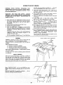
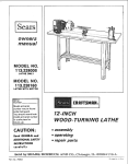
Serial
Number
Model and serial
number may be found
at the rear
of the base.
You should record both
model and serial number
in a safe place for
future use.
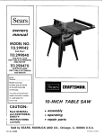
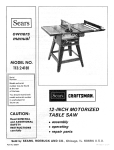
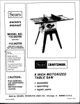
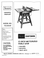
12-iNCH MO TORIZED
TABLE SAW
CAUTION:
Read GENERAL
and ADDITIONAL
SAFETY
iNSTRUCTiONS
• assembly
e operating
carefully
Sold by SEARS,
Part No. 62732
• repair
ROEBUCK
AND
parts
CO.,
Chicago,
IL. 60684
U.S.A.
FULL ONE YEAR WARRANTY
If within
one year from
workmanship,
the date of purchase,
Searswill
this Craftsman
TABLE SAWS
Table Saw fails due to a defect in material
by simply contacting
gives you specific
the nearest
legal rights, arid you
may
Sears store or Service
also have other
safety
1. KNOW YOUR
the
instructions
POWER TOOL
owner's
manual
vary from state to
2, GROUND
Learn
as
the
its
specific
ALL TOOLS
tool
is equipped
working
3-conductor
IN PLACE
order,
and
power
Use clamps
safer than
tool.
14. DON'T
With an approved
cord and a 3-prong grounding
type plug to fit the
proper ground ng type receptacle.
The green conductor
in the cord is the grounding
wire. Never connect the
green wire to a live terminal,
3. KEEP GUARDS
for
in
proper
adjustment
and
15. MAINTAi
footing
and balance
It's
at all times.
sharp
and clean
Follow
instructions
for
for
best and
lubricating
safest
and
accessories.
16. DISCONNECT
TOOLS
servicing;
17. AVOID
Form habit of checking to see that keys and adjusting
wrenches are removed from tool before turning
it on.
practical.
N TOOLS WITH CARE
Keep
tools
performance.
when
blades, bits, cutters,
AND WRENCHES
when
OVERREACH
before
KEYS
or a vzse to hold work
using your hand. frees both hands to operate
Keep proper
changing
alignment,
4. REMOVE ADJUSTING
tools
13. SECURE WORK
carefully,
application
and limitations
as well
potential hazards peculiar to this tool.
in
the
SEARS, ROEBUCK AND CO.
BSC 41-3
SEARS TOWER
CHICAGO, IL 60684
general
This
Center throughout
rights which
state.
Read
or
repair it, free of charge.
Warranty service is available
United States.
This warranty
ON CRAFTSMAN
changing
ACCIDENTAL
Make. sure switch
accessories
such
as
etc.
STARTING
is in "OFF"
position
before
plugging
In.
5. KEEP WORK AREA CLEAN
Cluttered
must not
6. AVOID
areas and benches
invite accidentS.
be Slippery due to wax or sawdust.
DANGEROUS
Don't
use power
expose them
to
Provide
adequate
tools
rain.
Al! visitors
area.
should
9. DON'T
work
a safe distance
from
work
switches,
or
by
10. USE RIGHT
safer at the rate for which
TOOL
to do a job
it was not
wear loose clothing,
Do not
store
GOGGLES
ON TOOL
could
occur if the tool is tipped
is accidentally
materials
or if the
contacted.
above or near the tool
such that
to stand on the tool to reach them.
DAMAGED
further
PARTS
use of the tool,
a guard or other
part that
is damaged should be carefully
checked to ensure that it
wit! operate properly
and perform
its intended
function.
Check
parts,
for alignment
breakage
of
that
that
of moving parts,
parts,
mounting,
binding
and
may .affect
its operation.
A
is damaged should be properly
of moving
any
other
guard or
repaired
or replaced.
gloves, neckties
or jewelry
(Head Protection)
I
Wear Safety goggles (must comply with ANS
Z87.1) at
all times, Also, use face or dust
mask if cutting
operation
is dusty, and ear protectors (piugs,or muffs_
extended
tool
conditions
other part
(rings,
wrist watches)
to get caught in moving
parts.
Nonslip
footwear
is recommended.
Wear protective
hair covering
to contain
long hair_ Roll Iongsleeves
above the elbow,
during
cutting
Before
11. WEAR PROPER APPAREL
12. USE SAFETY
injury
20. CHECK
Don't force tool or attachment
designed for.
Do not
Serious
removing
FORCE TOOL
It will do the .,ob betterand
it was designed,
ACCESSORIES
Consult
the
owner's
manual
for
recommended
accessories
Fo low the instructions
that accompany
the accessories.
The use of improper
accessories may
cause hazards.
it is necessary
KID-PROOF
master
18. USE RECOMMENDED
19. NEVER STAND
space.
AWAY
be kept
8. MAKE WORKSHOP
-- with
padlocks,
starter keys.
ENVIRONMENT
in damp or wet locations
or
Keep work area well lighted.
surrounding
7. KEEP CHILDREN
Floor
per_6Cls of operation.
".........
21. DIRECTION
Feed work
of rotation
OF FEED
into a blade or cutter against
of the blade or cutter only.
22 NEVER LEAVE
.... UNATTENDED
Turn
power
complete
off;
stop.
the eirection
TOOL RUNNING
Don't leave
tool
until
it comes to a
ADDITIONAL
SAFETY iNSTRUCTiONS
FOR TABLE SAWS
contact
the rear of the revolving
blade can be
thrown back at the operator at excessive speed. This
can usually be avoided by keeping the guard and
spreader
in
place
for all "THRU-SAWING"
operations (sawing entirely thru the work) AND by
removing all loose pieces from the table with a long
stick of wood IMMEDIATELY
after they are cut
off.
WARNING:
FOR YOUR OWN SAFETY,
DO NOT
OPERATE
YOUR SAW UNTIL
iT IS COMPLETELY
ASSEMBLED AND INSTALLED
ACCORDING TO THE
INSTRUCTIONS
... AND UNTIL YOU HAVE READ
AND UNDERSTOOD THE FOLLOWING.
GENERAL SAFETY INSTRUCTIONS
FOR POWER
TOOLS...
SEE PAGE 2
2.
GETTING TO KNOW YOUR SAW... SEE PAGE 15
3. BASIC SAW OPERATION...
SEE PAGE 17
4. ADJUSTMENTS...
SEE PAGE 23
SEE PAGE 26
5. MAINTENANCE...
1°
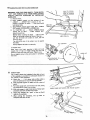
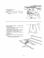
STABILITY OF SAW
If there is any tendency for the saw to tip over or move
during certain Cutting operations such as cutting
extremely large heavy panels or long heavy boards, the
saw should be bolted down.
If you attach any kind of table extensions over 24 in.
wide, make sure they are supported underneath by a
sturdy brace attached to saw base or bench.
6.
D.
E.
F.
G.
H.
LOCATI ON
The saw should be positioned so neither the operator
nor a casual observer is forced to stand in line with the
saw blade.
7.
KI CKBACKS
Kickbacks
can cause serious injury:
A "KICKBACK"
occurs when a part of the workpiece binds between the
sawblade and the rip fence or other fixed object, rises
B.
from the table, and is thrown
toward
I.
J.
the operator.
Keep your face and body to one side of the sawblade,
out of line with a possible "Kickback."
Kickbacks
and possible injury
from
them - can
usually be avoided by:
A. Maintaining
the rip fence parallel
B.
C.
D.
E.
F.
G.
H.
9.
to the sawblade.
Keeping the sawblade sharp. Replacing antikickback
pawls when points become dull.
Keeping sawblade guard, spreader, and antikickback
pawls in place and operating properly.
The spreader
must be in alignment
with
the sawblade and the
pawls must stop a kickback once it has started.
Check their action before ripping.
NOT ripping work that is twisted or warped or does
not have a straight edge to guide along the rip fence.
NOT releasing work until you have
way past the sawblade.
Using a "PUSH
STICK"
(See Page
widths of 2 to 6 in,, and an auxiliary
block for ripping widtt_s narrower
"Basic Saw Operation Using The Rip
pushed
16) for ripping
fence and push
than 2 in. (See
Fence" section.)
NOT confining
the cut-off piece when ripping
or
crosscutti ng.
When ripping apply the feed force to the section of
the workpiece
between the saw blade and the rip
fence.
power cord ..
cease operating immediately
until
the particular part is properly repaired or replaced.
C.
Wear safety goggles that comply
and a face shield if operation
plugs
or
operation.
muffs
Small
pieces
loose
with ANS! Z87.1,
is dusty. Wear ear
during
extended
of wood
or other
L.
M.
it all the
PROTECTION:
EYES, HANDS,
FACE, EARS, BODY
A. If any part of your saw is malfunctioning,
has been
damaged or broken..,
such as the motor switch, or
other operating
control,
a safety
device or the
B.
K.
periods
objects
of
that
Use
extra
caution
when
the
guard
assembly
is
removed
for resawing,
dadoing,
rabbeting,
or
molding
replace the guard
as soon as that
operation is completed.
NEVER
turn the saw "ON"
before clearing the
table of all tools, wood scraps, etc., except the
workpiece and related feed or support devices for
the operation planned.
NEVER
place your face or body in line with the
cutting tool.
NEVER
place your fingers or hands in the path of
the sawblade or other cutting tool.
NEVER
reach in back of the cutting
tool with
either hand to hold down or support the workpiece,
remove wood scraps, or for any other reason. Avoid
awkward operations
and hand positions where a
sudden slip could cause fingers or hand to move
into a sawbtade or other cutting tool.
DO NOT perform any operation "FREEHAND"
always use either the rip fence or the miter gauge to
position
and guide the work.
NEVER use the rip fence when crosscutting or the
miter gauge when ripping. DO NOT use the rip
fence as a length stop.
Never hold onto or touch the "free end" of the
workpiece or a "free piece" that is cut off, while
power is "ON"
and/or the sawblade is rotating.
Shut "OFF"
the saw and disconnect the power cord
when
removing
the table
insert,
changing
the
cutting tool, removing or replacing the blade guard,
or making adjustments.
Provide adequate support to the rear and sides of
the saw table for wider or long workpieces.
Plastic and composition
(like hardboard) materials
may be cut on your saw. However, since these are
usually
quite hard and slippery, the antikickback
pawls may not stop a kickback.
Therefore.
be especially
attentive
to following
proper
set-up and cutting procedures for ripping.
Do not stand, or permit anyone else to stand, in line
with a potential kickback.
N.
DO NOT perform layout, assembly, or setup work
on the table while the cutting tool is rotating.
O.
If you stall or jam the sawblade in the workpiece,
turn saw "OFF",
remove the workpiece
from the
sawblade,
and check to see if the sawblade
is
parallel to the miter
gauge grooves and if the
spreader is in proper alignment with the sawblade.
If ripping at the time, check to see if the rip fence is
parallel
with
the sawblade.
Readjust
as indicated.
10. KNOW YOUR CUTTING
TOOLS
A Dull, gummy, or improperly
sharpened or set cutting
tools can cause material
to stick, jam. stall the saw
or kickback
at the operator,
Minimize
potential
injury
by proper
cutting
too_
and mach{ne maintenance.
NEVER
ATTEMPT
TO
FREE
A STALLED
SAWBLADE
WITHOUT
F_RST
TURNING
THE
SAW OFF.
17. Always maintain control of the workpiece -- DO NOT
"let go" the workpiece until the cutting tool has come
to a stop.
18. IF YOUR SAW MAKES AN UNFAMILIAR
NOISE OR
IF
IT
VIBRATES
EXCESSIVELY
CEASE
OPERATING
IMMEDIATELY
UNTIL THE SOURCE
HAS
BEEN
LOCATED
AND
THE
PROBLEM
CORRECTED.
B. Never use grinding wheels, abrasive cut-off wheels,
friction wheels (metal slitting blades) wire wheels or
buffing wheelS.
11. USE ONLY
SAW.
ACCESSORIES
DESIGNED
FOR THIS
12. Crosscutting operations are more conveniently worked
19. If any part of this table saw is missing or should break,
bend or fail in any way, or any electrical component
fail to perform properly, shut off power switch, remove
cord from power supply and replace damaged, missing
and/or failed parts before resuming operation.
functioning of the sawblade guard.
13; Make sure the top of the arbor or Cutting tool rotates
toward
you when standing in normal operating
position. Also make sure the cutting tool, arbor collars
and arbor nut are installed properly. Keep the cutting
tool as low as possible for the
operation being
performed. Keepall guards in place whenever possible.
14. Do not use any blade or other cutting tool marked for
an operating speed less than 3450 RPM. Never use a
cutting tool larger in diameter than the diameter for
which the saw was designed. For greatest safety and
efficiency when ripping, use the maximum diameter
blade for which the saw is designed,since under these
conditions the spreader is nearest the blade.
15. Adjust table inserts flush with the table top. NEVER
Operate the saw unlessthe proper insert is installed.
16. Never feed material into the cutting tool from the rear
of the saw. An accident and seriousinjury could result.
20. THINK SAFETY.
Safety is a combination of operator common senseand
alertness at all times when the saw is being used.
21. NOTE
AND FOLLOW SAFETY
INSTRUCTIONS
THAT APPEAR ON THE FRONT OF YOUR SAW.
FOR
READ
AND
WEAR
SAFETY
YOUR
USE
i
SAW
KEEP
USE
I
il
SAFETY
BLADE
HANDS
OWNER'S
OPERATING
MANUAL
MACHINE
GOGGLES
GUARD
OUT
OF
FOR
PATH
"'THRU-SAWING-
OF
SAWBLADE
A "PUSH-STICK"
KNOW
DO
OWN
UNDERSTAND
BEFORE
1
MOT
NEVER
WHEN
REQUIRED
DANGER
AVOID
"KICKBACKS"
HOWTO
PERFORM
REACH
OPERATIONS
AROUND
OR
"F REEHANDOVER
SAW
BLADE
22. WARNING:
DO NOT
ALLOW
FAMILIARITY
(GAINED FROM FREQUENT USE OF YOUR SAW)
TO
BECOME
COMMONPLACE.
ALWAYS
REMEMBER THAT A CARELESS FRACTION OF A
SECOND IS SUFFICIENT
TO INFLICT
SEVERE
INJURY.
WEAR YOUR
The operation of any power tool can result in foreign
objects being-thrown
into the eyes, which can result in
severe eye damage. Always wear safety goggles complying
with ANSI Z87.1 (shown on Package) before commencing
power tool operation. Safety Goggles are available at Sears
retail or catalog stores.
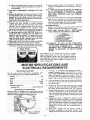
MOTOR SPECIFICATIONS
AND
ELECTRICAL REQUIREMENTS
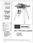
MOTOR SPECIFICATIONS
1. "If
The AC motor used in this saw is a capacitor start,
non-reversible type, with the following specifications:
Voltage .................................
Amperes ..................................
Hertz ...................................
Phase ............
....................
RPM ..................................
Rotation (viewed from
sawblade end) ...............
MOTOR
SAFETY
motor
is overloaded
and overload protector
is
actuated (stopping motor) BE POSITIVE
you push
switch "OFF" immediately and allow the motor to cool
before attempting to reset the protector. Since the
protector is near the sawblade,.the switch must not be
240
7
60
Single
3450
turnee
"ON"
until
after
you
have reset the protector.
2.
If the red button
will hot snap into place immediately,
the motor
is still too hot and must be allowed to cool
3.
As
for a while
Counterclockwise
soon
longer.
as the
red
button
will
snap
into
position,
the saw may be started and operated
by moving the saw switch
lever to the "ON"
PROTECTION
4.
The saw motor
is equipped
with a manual-reset
thermal
overload protector,
designed to open the power line circu it
when the motor temperature
exceeds a safe value.
running
normally
position.
Frequent opening of fuses or circuit
breakers may result
if motor
is overloaded,
or if the motor circuit
is fused
with a fuse other than those recommended.
Do not use
a fuse of greater
capacity
without
consulting
the power
company.
5.
//
6.
O
TECTOR
J
(RED BUTTON)
4
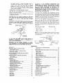
Although
the motor
is designed for operation
on the
voltage and frequency
specified on motor
nameplate,
normal
loads will be handled
safely on voltages
not
more than 10% above or below the nameplate
voltage.
terminals be not less than the voltage specified on
nameplate.
Most motor
troubles may be traced to loose or
Heavy
incorrect
loads,
connections,
however, require
overloading,
that voltage
reduced
at motor
input
voltage (which results when small size wires are used in
the
supply
circuit)
or when
the supply
circuit
is
extremely
tong. Always
check connections,
load and
supply
circuit
when
the motor
fails
to
perform
satisfactorily.
Check wire sizes and lengths with
the
WARNING:
IF
NOT
PROPERLY
GROUNDED
THiS
POWER TOOL CAN INCUR THE POTENTIAL
HAZARD
OF
ELECTRICAL
SHOCK,
PARTICULARLY
WHEN
USED
IN
DAMP
LOCATIONS,
IN
PROXIMITY
TO
table in the next paragraph.
or worn cord immediately.
PLUMBING,
OR OUT OF DOORS.
IF AN ELECTRICAL
SHOCK
OCCURS
THERE
IS THE POTENTIAL
OF A
SECONDARY
HAZARD
SUCH
AS YOUR
HANDS
CONTACTING
THE SAWBLADE.
CONNECTING
TO POWER
Replace
SOURCE
CAUTION:
in
use to protect
or cut, or damaged
This saw is wired
damaged
OUTLET
This saw must be grounded
while
operator
from electrical
shock.
If power cord is worn
it replaced immediately.
or repair
in any way,
for operation
on 240
the
have
volts
only. Connect to a 15 ampere branch circuit protected by a
15 ampere
time
delay or circuit saver fuse or circuit
breaker.
WARNING:
Do not permit fingers to contact the terminals
of power or motor plugs when installing or removing the
plug to or from a live power source. Hold the plug as
shown.
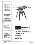
GROUNDINGBLADE
_s
LONGEST
OF 3 BLADES
This power tool is equipped
with a 3-conductor
cord and
grou nding type plug which has a ground ing prong, approved
by Underwriters'
Laboratories
and the Canadian Standards
Association.
The ground
conductor
has a green lug and is
attached
to the tool housing at one end and to the ground
prong in the attachment
plug at the other end.
The use of any extension
cord will cause some loss of
power.
To
keep
this
to a minimum
and to prevent
over-heating
and motor
burn-out,
use the table below to
determine
the minimum
wire size (A.W:G.)
extension
cord.
Use only
3 wire extension
cords
which
have 3 prong
grounding
type lugs and 3-pole receptacles which accept the
tools plug.
Extension
Up
Cord
200
j
BOX
NO
ADAPTER
THIS
iF YOU
ARE
NOT
SURE
THAT
PROPERLY
GROUNDED,
HAVE
QUALIFIED
ELECTRICIAN.
TYPE
14
......................
12
ft. to 400 ft .......................
8
NOTE:
For circuits
of greater length, the wire size must be
increased proportionately
in order to deliver ample voltage
to the saw motor.
GROUNDED
OUTLET
AVAILABLE
Wire Size A.W.G,
to 100 ft .........................
100 ft. to 200ft
/
Length
IS
FOR
'-'_
,_,_ SWITCH
t
PLUG
YOUR
OUTLET
IS
IT CHECKED
BY A
WARNING:
DO NOT PERMIT FINGERS TO TOUCH
THE TERMINALS OF PLUGS WHEN INSTALLING
OR
REMOVING THE PLUG TO OR FROM THE OUTLET.
GROUND
GROUND
CONTENTS
WARRANTY
.................................
2
GENERAL
SAFETY
INSTRUCTIONS
FOR POWER TOOLS
.........................
2
ADDITIONAL
FOR TABLE
3
MOTOR SPECIFICATIONS
AND ELECTRICAL
REQUIREMENTS
............................
ASSEMBLY
..................................
Attaching
Legs ...............................
Checking Table Insert
.........................
Checking
Blade Squareness to Table
..............
Attaching
Table Extension
.....................
Installing
Rip Fence Guide Bars ..................
Aligning
Rip Fence
..........................
Adjusting
Rip Scale Pointer
....................
Installing
Blade Guard
........................
GETTING
TO KNOW YOUR SAW
...............
On-Off Switch
..............................
Elevation
Handwheel
.........................
Elevation
Lock
.............................
Tilt Crank
.................................
Rip Fence
.................................
Miter Gauge ................................
Blade Guard ................................
Table insert
................................
and
Exacti-Cut
SAFETY
INSTRUCTIONS
SAWS ...........................
UNPACKING
AND CHECKING
CONTENTS
Tools Needed ................................
List of Loose Parts ............................
Removing
4
........
6
6
6
7
7
7
8
8
9
11
12
12
14
14
15
15
15
15
15
15
15
Installing
Sawblade
...............
16
.................................
BASIC SAW OPERATION
USING
Work Helpers
...............................
Crosscutting
................................
16
THE
MITER
GAUGE
Repetitive
Cutting
...........................
Miter Cutting
...............................
Bevel Crosscutting
...........................
Compound
Miter Cutting
......................
BASIC SAW OPERATION
USING
Ripping
...................................
Bevel Ripping
..............................
Resawing
..................................
Cutting
Panels
..............................
Rabbeting
.................................
ADJUSTMENTS
..............................
Miter Gauge ................................
Heeling Adjustment
or Parallelism
Sawblade to Miter Gauge Groove
Blede Tilt, or Squareness of
Blade to Table
.............................
Elevation
Lock
.............................
MAINTENANCE
LUBRICATION
RECOMMENDED
TROUBLE
REPAIR
18
19
19
19
RIP FENCE
...............
23
24
26
2'3
27
...............
........................
..............................
20
20
20
22
22
22
of
.............................
ACCESSORIES
..
23
23
..............................
SHOOTING
PARTS
THE
17
t7
18
2?
2£,
30
UNPACKING
/_
TOOLS
CONTENTS
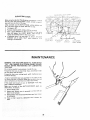
CAUTION: Never use gasoline, naptha or similar highly
volatile solvents.
NEEDED
Hammer
........
_:_
AND CHECKING
Apply a coat of automobile wax to the table.
Wipe all parts thoroughly with a clean, dry cloth.
WARNING:
FOR YOUR
OWN SAFETY,
NEVER
CONNECT PLUG TO POWER SOURCE OUTLET UNTIL
ALL ASSEMBLY STEPS ARE COMPLETE, AND YOU
HAVE READ AND UNDERSTAND
THE SAFETY AND
OPERATIONAL
INSTRUCTIONS.
Medium Screwdriver
Small Screwdriver
LiST OF LOOSE
1/2 in.
3/4 in.
Combination Square
COMBINATION
STRAIGHT
LIGHT
LINE
ON
EDGE
THICK•
OVER
1
GAP
BE NO
WHEN
IN
SQUARE
DOTTED
A
B
C
D
E
F
G
H
J
K
L
M
N
BOARD
EDGE
MUST
STRAIGHT.
/
\i 1
[JII
,
HERE
OF
THIS
BE PERFECTLY
_A_DALONGTHIS
EDGE.
,,% _
SHOJLD
Item
Part Marne
Qty.
SQUARE MUST BE TRUE.
3/4"
DRAW
PARTS
9/16 in.
OR
I
I
OVERLAP
IS FLIPPED
POSITION,
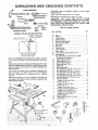
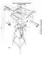
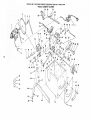
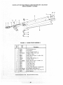
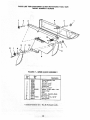
Model 113.24250 Motorized Table Saw isshipped complete
in one carton including Two Table Extensions and Steel
Legs....
Separate all parts from packing materials and check each
one with the illustration and the list of Loose Parts to make
certain all items are accounted for, before discarding any
packing material.
If any parts are missing, do not attempt to assemble the
table saw, plug in the power cord or turn the switch on
until the missing parts are obtained and are installed
correctly.
Remove the protective oil that is applied to the table top
and edges of the table. Use any ordinary household type
grease and spot remover.
O
O
O
O
P
Q
R
R
R
R
R
R
S
S
S
J
T
T
U
V
W
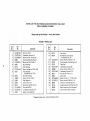
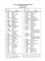
Leg .....................................
Stiffener .................................
Table Extension...........................
SpreaderSupport ..........................
BladeGuardandSpreader ...................
FenceGuideBar(Rear) .....................
Miter Gauge ..............................
Rip Fence ...............................
GuideBarRod ............................
Arbor Nut Wrench .........................
Arbor Wrench ............................
FenceGuide Barwith Rip Scale (Front) ........
OwnersManual ...........................
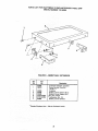
Pkg.of Miscellaneous
SmallPartsNo. 62596
Consistingof the Following:
SetscrewWrench,3/32 in...................
SetscrewWrench,1/8 in ....................
SetscrewWrench,5/32 in...................
SetscrewWrench,3/1G in...................
Switch Key .............................
Self-ThreadingNut .......................
Hex HeadScrew,5/16-18 x 1-1]2 in. long .....
Hex HeadScrew,5/16-18 x 1 in. long ........
Hex HeadScrew,5/16-18 x 5/8 in. long ......
Hex HeadScrew,1/4-20 x 1/2 in. long .......
Hex HeadScrew,5/16-18 x 1-1/4 in. long .....
Hex HeadScrew,1/4-20 x 5/8 in. long .......
Hex Nut, 5/16-18
(approx. dia.of hole 5/16 in.) .............
Hex Nut, 1/4-20
(approx. dia.of hole1/4 in.) ..............
Hex Nut, 1/2-13
(approx. dia.of hole1/2 in.) ..............
L0ckwasher,5/16 in. ExternalType
(approx.dia.of hole5/16 in.) .............
L0ckwasher,1/4 in. ExternalType
(approx.dia.of h01e1/4 in.) ..............
Guide BarSpacer ........................
Thumbscrew,5/16-18 x 1 in. long ...........
LevelingFoot ...........................
y
• 6
W
4
4
2
1
1
1
I
1
1
1
1
1
1
1
1
1
1
2
2
2
2
16
16
8
2
28
18
8
28
18
2
1
4
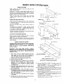
ASSEMBLy
LEG
END
STLFFENER
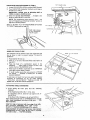
ATTACHING
LEGS
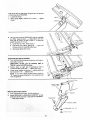
1. Turn the saw upside down.
NOTE: DO NOT LAY IT ON THE FLOOR AS THIS
MAY SCRATCH THE TABLE SURFACE. PLACE IT
ON STRIPS OF WOOD OR PARTS OF THE PACKING
MATERIAL.
2. From among the loose parts, find the following
hardware:
16 Hex. Head Screws, 5/16-18 x 5/8 in. long
16 Hex. Nuts, 5/16-18 (approx. din. of hole, 5/16 in.)
16 Hex. Head Screws, 1/4 in.-20 x 1/2 in. long
16 Hex. Nuts, 1/4--20 (approx. din. of hole, 1/4 in.)
8 Hex. Nuts, 1/2--13 (approx. din. of hole, 1/2 in.)
4 Leveling Feet
16 Lockwashers, 1/4 in. External Type (approx. din. of
hole, 1/4 in.)
16 Lockwashers, 5/16 in. External Type (approx. din.
of hole, 5/16 in.)
NOTE: The four stiffeners are identical. BE SURE TO
ATTACH
THE SIDE STIFFENERS
USING THE
OUTER HOLES ...
ATTACH END STIFFENERS
USING INNER HOLES.
3. Insert screws through legs then through stiffeners.
Install Iockwashers and nuts. DO NOT TIGHTEN.
4. After all screws, washers and nuts are installed, tighten
all nuts.
5.
6.
SIDE STIFFENER
5/16
-18
x 5/8
Install leveling feet.
Place saw in upright position.
BEFORE PROCEEDING WITH THE ASSEMBLY, THE
TABLE INSERT, BLADE SQUARENESS, AND BLADE
PARALLELISM
MUST BE CHECKED AT THIS TIME.
CHECKING
1.
Insert
TABLE INSERT
should
be flush with
table
top,
Check
as shown.
Loosen flat head screw that holds insert and adjust the
four set screws as necessary. Tighten
flat head screw.
Do not tighten
insert.
screw to the
point
whereit
deflects
the
2.
To remove insert.
A) Loosen Screw
B) Lift insert from front end, and pull toward front of
3.
To replace insert.
Place insert into insert opening in table and push
toward rear of saw to engage spring clip and until
keyslot in insert will drop over screw. Tighten screw.
Do not tighten screw to the point where it will deflect
the insert.
saw.
\
3/'32 IN.
SETSCREW WRENCH
CHECKING
BLADESQUAR
ENESS
TOTABLE
TILT CLAMP
1. Loosen ELEVATION LOCK by pulling KNOB forward.
2. Turn ELEVATION
handwheel clockwise until blade is
as high up as it will go.
IMPORTANT:
BLADE must be SQUARE (90 ° ) to
TABLE, in order to ALIGN rip fence.
3." Check for BLADE SQUARENESS...
if blade is not
squareto table, adjust it at this time.
KNOB
ELEVATION
HANDWHEEL
NOTE: The combination square must be "true" -- see
start of "Unpacking and Checking Contents" section on
page 6 for checking method.
Refer to "BLADE TILT, OR SQUARENESS
TO TAB LE" adjustments on page 24.
OF BLADE
TILT
CRANK
ELEVATION'
LOCK
KNOB
MAKE SURE SQUARE
IS NOT TOUCHING
TIP OF TOOTH
SAWBLADE PARALLELISM
MARK
The sawblade must be parallel to the miter gauge slots and
the rip fence in order to prevent
heeling. To check for
parallelism:
1.
Raise blade all theway
2.
Mark an "'x" on one of the teeth
the LEFT.
up.
3.
Place the
head of a combination
square
in the
GROOVE
, . . adjust blade of square so that it just
touches the tip of the MARKED
tooth.
4.
Move square to REAR, rotate blade to see if MARKED
tooth again touches blade of square,
5.
If tooth touches square the same amount
and REAR
. . . sawblade
is PARALLEL
GAUGE GROOVE.
which
is SET
(bent)
to
at FRONT
to MITER
If tooth does not touch front and rear, adjust immediately
according
to instructions
on pg. 23 under
heading:
"'HEELING
ADJUSTMENT:
PARALLELISM
OF
SAWBLADE
TO MITER GAUGE GROOVE,"
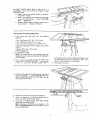
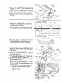
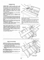
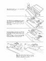
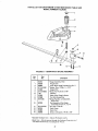
ATTACHING
1.
TABLE
From among the
hardware:
EXTENSIONS
loose
8 Hex Head Screws 5/16--18
parts
find
the
following
x 1-1/4 in. long
8 Lockwashers, 5/16 in. External Type (approx. alia. of
hole 5/16 in.)
8 Hex Nuts, 5/16-18 (approx. dia. of hole 5/16 in.)
insert screws through holes in EXTENSION then through
table. Install Iockwashers and screw on the nuts .,. DO
NOT TIGHTEN.
Align front edge of extension with front edge of saw table.
Pull Extension UPWARDS above table surface ...
SLIGHTLY TIGHTEN SCREWS using 1/2 in. wrench.
Using small block of hardwood and hammer, tap extension
DOVVNWARDS at front, center & rear, until it is EVEN
with table surface ... TIGHTEN SCRE_/S.
BLOCK
OF WOOD
\
/
/
"X"
ON
TOOTH
Lay
REAR
FENCE
straightedge.
If outer
than table surface;
GUIDE
BAR
on
edge of extension
holding
table to
is higher
bracket
act as a
or lower
A.
Slightly
loosen nuts
using 7/16 in. wrench.
to extension
B.
Move end of extension
up or down until outer edge
is even with table surface
...
check with GUIDE
BAR ... tighten nuts.
C.
Recheck INNER
edge of extension
to make sure it
has not moved ... readjust, if necessary,
\
\
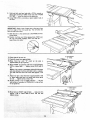
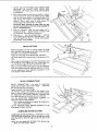
mNSTALLING
RiP FENCE GUIDE BARS
From
among
hardware:
the
parts
2 Hex. Head Screws,
5/16-18
2 Hex. Head Screws,
5/16-18x
4 Hex. Nuts, 5/16
4 External
5/16 in.)
2 Self-threading
find
x 1-1/2
5/16
the
following
in. long
1 in. long
18 (approx.
Lockwashers,
2 Spacers, 3/4
2,
loose
dia. of hole 5/16
in. (approx.
in. dia. x 1/2 in. long
nuts
Lay guide bars on table.
NOTE: The various holes
in the bars allow
them
repositioned
on the saw and also makes them
to other models.
3.
8.
be
the FIRST
hole
... insert another
1-1/2
LARGE
in.
long
screw
through
hole
at
just
get
Insert 1 in. long screws 'n FIRST
and THIRD
rear bar and attach to table the same way.
holes
of
Insert
round
through
Remove
EXTREME
LEFT
SIDE OF SWITCH
BRACKET
through
SIXTH
hole in bar. Hold them in place
piece of masking
tape from the underside,
4.
Place spacers
on screws.
holes in middle and on right side of
...
install !ockwashers
and nuts.
DON'T
SCREW NUTS ON
them started on the screws.
7.
to
adaptable
Insert 1-1/2 in. long screw through
from the LEFT IN THE FRONT BAR
Insert bolts through
front
of saw table
6o
in.)
dia. of hole
the 3 screws from
ALL
THE
WAY,
rear of table extension.
ends of FENCE
GUIDE
holes at outer end of bars.
BAR
ROD
\
NOTE:
The ends of the ROD are not threaded
., . the
SELF THREADING
NUTS will cut threads on the rod
as they are screwed on.
\
ther_
with a
9.
Hold rod with
one hand and with
a 7/16
in. wrench
or
pliers start screwing on ONE of the nuts only ,A TURN
OR TWO ... screw on other nut the same way.
10. Using TWO
the nuts.
7/16
in. wrenches
or pliers tighten
both of
IMPORTANT: Apply a coat of paste wax to the top surface
and front edge of the front guide bar. This will allow the
fence to slide more easily.
11. Slide the bars so that screws are in the MIDDLE
slotted holes.
of the
12. Position rip fence over miter gauge groove, holding up
the rear end while engaging front end with bar ...
Iower fence onto table.
8 THICKNESSES
13. Raise blade all the way up.
of rear guide bar.
8 THICKNESSES
OF PAPER
19. Move fence to RIGHT edge of table . .. make sure it is
approx. 1/32 in. above table at front and rear and
tighten screws.
•
10
ALiGNiNG
RIPFENCE
The
fence
should
slide
remain
in alignment
grooves).
easily
(parallel
along
the
to sawblade
The alignment
is maintained
by
fence which bears against the front
To move the fence, loosen the
fence with one hand at the front.
bars and always
and miter
a spring underneath
guide bar.
lock
gauge
the
handle and grasp the
For very close adjustments, grasp the guide bar with both
hands and move the fence with your thumbs.
/
Place fence on saw but DO NOT
LOCK
IT,
Move the REAR END of the fence slightly to the right or
left
...
when you release it, the fence should "'spring'"
back to its original position.
If it does not, the spring
1.
Loosen
2.
Move Spring slightly
pressure must be INCREASED.
the screws.
toward
front
of fence.
11
If the fence does not slide easily along the bars. the pressure
of the spring can be R EDUCED.
1. Loosen the screws.
2.
SPRING
Move spring slightly toward rear of fence . .. tighten
screws.
SCREWS _
\\
HEX SCREWS
,
The rip fence must be PARALLEL with the sawblade
and Miter Gauge grooves ...
Move fence until it is
along side of groove. Do NOT LOCK IT. It should be
parallel to groove. If it is not;
A. Loosen the two "Hex. Head Screws."
:E NCE
B. Hold fence head tightly against bar .., move end
of fence so that it is parallel with groove,
C. Alternately tighten the screws.
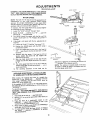
ADJUSTING RIP SCALE POINTER
1. Turn ELEVATION handwheel clockwise until blade is
up as high as it will go.
IMPORTANT:
BLADE must be SQUARE |90o| to
TABLE, in order to ALIGN rip fence.
2. Position fence on right side of sawblade so that it
touches the sidesof the teeth..,
tighten lock knob.
3. Loosen screw holding the pointer..,
adjust pointer so
that is points to "0"...
tighten screw.
NOTE: If you cannot adjust pointer sothat it points to
"0", loosen the screws holding the front guide bar and
move the guide bar.
INSTALLING
1.
2.
XLOCK
v4-2ox 5/8 //
BLADE GUARD
From amoung the loose parts, find the hardware.
Attach SPREADER to SPREADER SUPPORT so that
screws are all the way back in the SLOTS of SUPPO RT
... hand tighten screws,
I_
_
SI_EADER
'_
SUPPORT
EXT. I/4
I
NUT,
12
HEX
I/4
HANDLE _
3.
Slide support onto SUPPORT ROD until PIN in rod fits
into notch in support
...
insert THUMB
SCREW and
tighten it.
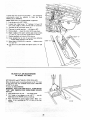
4.
Loosen setscrew in end of SPREADER
in. setscrew wrench.
5.
Slide guard to right
6.
Make sure blade
it will go.
until
BAR
using 5/32
end of rod is even with
is square to table
bar.
and raised as high as
SUPPORT ROD
/
IMPORTANT:
PARALLEL
The
SPREADER
must
always
be
to the sawblade and in the MIDDLE
of the
cut (KERF)
made by the sawblade.
NOTE:
KERF
7.
8.
The spreader is thinner
than the width of the
by approximately
sixteen thicknesses of paper.
Make seven folds
in a small
ordinary
NEWSPAPER
making
The folded
paper will
Place
FENCE
RIP
piece (10 x 10 in.)
eight thicknesses.
be used as a "spacing
on table...
KERF
SPACE EQUAL
TO APPROX.
8 THICKNESSES
OF PAPER
LOOKING
of
move
J
it
PAWLS...
insert one
in the notches to hold
10. Insert folded
paper between SPREADER
and FENCE
...
hold spreader flat against fence ... tighten
screws.
11. Now
tighten
setscrew
in end of spreader
12. To remove blade guard, loosen
guard off of SUPPORT
ROD.
NOTE:
Move fence away
spreader remains SQUARE
If it is not square
must be adjusted.
with
2 clamping
table,
A.
Loosen
B.
Rotate
C.
Check
alignment
of
readjust, if necessary.
bar until
from
with
screws,
spreader
thumb
bar.
screw
spreader
table.
the
using
and slide
to
SPREADER
a 1/2
is square wffh
spreader
...
with
see if
BAR
in. wrench.
table.
blade
WOOD
y--
gauge".
CAREFULLY
Lift
up both ANTIKICKBACK
of the SETSCREW
WRENCHES
the pawls out of the way.
SPREADER BAR A
SPACE EQUAL
TO APPROX.
8 THICKNESSES
OF PAPER
against blade so that it is parallel to the blade, and just
TOUCHES
tips of saw teeth . .. tighten
RIP FENCE
LOCK KNOB,
g.
I
and
7/16 IN.
WRENCH
FOLDED
PAPER
DOWN
ON
SAW
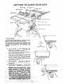
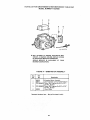
GETTING TO KNOW YOUR SAW
6 RiP FENCE
11 EXACT-I-CUT
7 MITER GAUGE
8 BLADE GUARD
ON-OFF
9
SWITCH
TILT LOCK
K.NOB
ELEVATION
LOCK
TABLE INSERT
HANDLE
TILT CRANK
2
ELEVATION HANDWHEEL
0
1
ON-OFF SWITCH
CAUTION: Before turning switch on, make sure the blade
guard is correctly installed and operating properly.
The On-Off Switch has a locking feature. THiS FEATURE
IS INTENDED
TO PREVENT
UNAUTHORIZED
AND
POSSIBLE HAZARDOUS
USE BY CHILDREN
AND
OTHERS.
@
KEY
(YELLOW PLASTIC)
B. TO turn saw ON . .. stand to either side of the
blade never in line with it ... insert finger under
switch lever and pull END of lever out.
After turning switch ON, always allow the blade to
come up to full speed before cutting.
Do not cycle the motor switch on and off rapidly,
as this may cause the sawblade to loosen. In the
event this should ever occur, allow the sawblade to
come to a complete stop and retighten the arbor
nut normally, not excessively. Never leave the saw
while the power is "ON".
C. TO turn saw OFF ... PUSH lever in. Never leave
the saw until the cutting tool has come to a
complete stop.
D. TO lock switch in OFF position .. • hold switch IN
with one hand ... REMOVE key with other hand.
FETY,
0
0
O
KEY
t
LOWER
LOW
D#
).
EN
WILL ¸
\
14
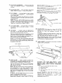
2
ELEVATION
blade. Turn
to lower.
3
4
HANDWHEEL
clockwise
to
ELEVATION
LOCK...
height.
in to LOCK...
PUSH
TiLT
Turn
CRANK
clockwise
to tilt
toward
. . . elevates or lowers
elevate
...
the
pieces,
counterclockwise
proper
facing
does
of the sawblade
not
interfere
with
out to unlock.
the
guard.
Select a suitable piece of smooth straight wood
two holes through
it and attach it with screws.
locks the blade at the desired
PULL
Be positive
operation
. - - drill
NOTE: When bevel crosscutting,
attach facing so that it
extends
to the right
of the miter gauge and use the
miter gauge in the groove to the right of the blade,
...
tilts the blade for bevel cutting.
to tilt toward left ... counterclockwise
right.
When the blade is tilted to the LEFT as far as it will go,
it should be at 45 ° to the table and the bevel pointer
should point 45 °.
NOTE:
There
are LIMIT
STOPS
inside
the saw which
prevent
the blade from tilting beyond 45 ° to the LEFT
and 90 ° to the RIGHT.
(See "Adjustments"
section
"Blade Tilt, or Squareness of Blade to Table").
F AC| I',,
STO
5
TiLT
LOCK
tilt position.
right to lock.
6
RiP
lock
KNOB
Turn
...
it to
the
left
blade in the desired
to unlock
...
FC)R STOP PIN
_
j__]
to the
8
FENCE . . . is locked in place by tightening
knob.
To move the fence, loosen the knob
grasp the fence with
Holes
facing
locks
the
the
and
one hand at the front.
BLADEGUARD
must always be in place and working
properly
for all thru-sawing
cuts. That
is, alt
cuts
whereby
the blade
cuts
completely
through
the
workpiece.
To remove the guard for special operations,
loosen
thumbscrew
and slide the guard off of the rod.
NOT DISTURB
THE SETTING
OF THE ROD.
are provided in the rip fence for attaching
a wood
when using the dado head, or molding head.
Select a piece of smooth straight wood approx.
3/4 in.
thick and the same size as the rip fence.
Attach
it to the fence with three Round Head -#10
the
DO
When replacing
the guard, make sure the P_N in the rod
engages with the NOTCH
in the spreader support.
Make
sure thumbscrew
is tightened
securely.
Wood Screws 2 in. long. To remove the facing, loosen
the screws, slide the facing forward
and pull the screws
through
the round holes.
9
TABLE
INSERT
blades or other
is removable
cutting
for removing
or installing
tools.
WOOD FACING
\
,
\
d
/
/
\
7
MITER
GAUGE
..,€
//
ROUND HEAD
//
# 10 WOOD SCREWS
. . . head
is locked
in position
crosscutting
or mitering
by tightening
the lock
ALWAYS
LOCK IT SECURELY
WHEN IN USE.
for
knob.
WARNING:
FOR
SWITCH
"OFF"
POWER
SOURCE
There are two slots for the stop pin at the 45 degree
right and left positions
for conveniently
setting
the
Miter Gauge to cut miters.
INSERT,
A. Lower
NOTE:
The slots for the stop pin and the graduations
are
manufactured
to very close
tolerances
which
provide
accuracy
for average woodworking.
In some
cases where extreme
accuracy is required, when making
angle cuts, for
example,
make a trial cut and then
recheck it.
If necessary, the miter gauge head can then
slightly
to compensate
and then locked.
YOUR
OWN
SAFETY,
TURN
AND
REMOVE
PLUG
FROM
OUTLET
BEFORE
REMOVING
the blade
B.
Raise blade guard.
C.
Loosen
D.
Lift
front
below
the table surface.
screw.
insert
from
of saw
front
end,
NEVER
OPERATE
THE
SAW
PROPER INSERT
IN PLACE. USE
INSERT
WHEN
,SAWING
COMBINATION
D ADO/MOLDING
DADOING
OR MOLDING.
be swiveled
Slots are provided
in the miter gauge for attaching
an
AUXILIARY
FACING
to make it easier to cut long
15
and
DU_I
toward
WITHOUT
-THE
THE SAW BLADE
, . .
USE
THE
_NSER_
WHE[_
I0
REMOVING
AND INSTALLING
SAWBLADE
\
WARNING:
FOR YOUR OWN SAFETY, TURN SWITCH
"'OFF" AND REMOVE PLUG FROM POWER SOURCE
Q,UTLET
BEFORE
REMOVING
OR INSTALLING
SAWB LAD E.
A. Remove insert.
B. Place ARBOR wrench on flat surfaces of saw
ARBOR ...
ARBOR NUT wrench on nut ...
position wrenches as shown ... hold your hands
well above blade.
C. With ARBOR wrench against table, PULL ARBOR
NUT wrench FOREWARD to LOOSEN nut.
D. To TIGHTEN
nut ...
HOLD ARBOR wrench
against rear of table ...
PUSH ARBOR NUT
wrench toward rear.
/ ,,
NOTE: When installing the blade.., make sure the
teeth are pointing toward the front of the saw...
and that the blade and collars are clean, and free
from any burrs.
The HOLLOW side of the collars must be against
the blade.
ARBOR
W_ENCH
Always tighten the arbor nut securely.
/
FLAT SURFACES
To replace
COLLAR
insert.
Place insert
toward
rear
keyslot
J
---_/l/
into insert
of saw to
in insert will
Do not tighten
the insert.
drop
opening
in table
engage spring
clip
and
and
over screw. Tighten
screw.
screw to the
point
where
push
until
ARBOR
it wil! deflect
l
TEETHPOINTING TO
FRONT OF SAW
11
EXACT-I-CUT
The "yellow" plastic disc imbedded in the table in front
of the sawblade, is provided for marking the location of
the "sawcut" on the workpiece.
A. Check disc ... if it is above table surface, place a
piece of hardwood on top of it and tap it down.
B. With blade 90 ° (square to table) cut off a piece of
wood.
C. Pull miter gauge back until wood is over disc. Using
very sharp pencil, mark a line on disc.
D. With miter gauge in right hand groove, follow same
procedure and mark another line on disc.
E. These lines indicate the "path" of the cut (kerr)
F. made
When by
cutting
the sawblade.
the workpiece,
workpiece with line on disc.
line
up
mark
_
BLADEGUARD NOT SHOWN FOR PICTURECLARITY
_/
on
_
16
_
NUT
BASIC
SAW OPERATION
WORK HELPERS
Before
"Basic
Notice
cutting
any wood
Saw Operations".
that
in
order
to
on
your
make
saw, study
some
of
the
all
of the
cuts,
it
is
M
necessary to use certain
devices "Work
Helpers"
like the
Push Stick, the Push Block and the Auxiliary
Fence/Work
Support,
which you can make yourself.
After
you
have
"helpers"
before
Stick"
first.
made a few
starting
any
practice
projects.
!5
cuts, make these
Make the "Push
T
PUSH STICK AND PUSH BLOCK
PUSH
Make the Push Stick using a piece of 1 x 2, or rip one from
a wide board, say 1 1-I/2"' wide, and set the rid fence 9-7/8
in. from the sawblade.
Make the
plywood.
Push
Block
using
a piece
of 3/8 in. and 3/4
the handle in the center of the plywood
with glue and wooascrews.
STICK
i_q[--
WORKPIECE
END
....._ _-. 1/4
NOTE: AIJ dimensions in inches
THESE EDGES MUST
BE PARALLEL
=n.
/
The small piece of wood 3/8 in. x 3/8 in. x 2-1/2 in. should
be GLUED
to the plywood...
DO NOT USE NAILS. This
is to prevent
dulling
the sawblade
in the event
you
mistakingly
cut into the push block.
Position
together
4.5° NOTCH
3/4
\
PLYWOOD
12
_"4-3/4_
\
\
and fasten
3/8
AUXI LIARY FENCE/WORK
SUPPORT
Make one using a piece of 3/8 in. and 3/4
Fasten together with glue and woodscrews.
in. plywood.
NOTE:
Since the Push Block is used with the Auxiliary
Fence, the 4-3/4 in. dimensions
must be held identical
on
both the pieces,
USING THE MITER
NOTE:
All dimensions
3/8
3/'8
in inches
3/8
GAUGE
PLYWOOD
3/'4 PLYWOOD
/
CROSSCUTTING, MITER CUTTING, BEVEL CUTTING,
COMPOUND MITER CUTTING and when RABBETING
across the end of a narrow workpiece, THE MITER
GAUGE IS USED.
j'_27-
]/2
WARNING:
FOR YOUR OWN SAFETY,
ALWAYS
OBSERVE THE FOLLOWING SAFETY PRECAUTIONS
IN ADDITION
TO THE SAFETY INSTRUCTIONS
ON
PAG ES 2, 3, and 4.
1.
THIS
Never make these cuts freehand
(without
using the
miter gauge or other auxiliary
devices) because the
blade could bind in the cut and cause a KICKBACK
or
EDGE
FACE AND
MUST
THIS
3/8
cause your fingers or hand to slip into the blade.
2.
Always
lock the miter
3.
Remove
4.
Make sure blade guard is installed for all "thru-sawing"
operations
(when
sawblade
cuts
entirely
thru
the
thickness
of
the
workpiece.)
Replace
guard
IMMEDIATELY
after completion
of dadoing,
molding
rip fence from
or rabbeting
5.
6.
7.
&
gauge securely
when
3O
BE PARALLEL
PLYWOOD
"\
in use.
15-1/2
71
NOTE: All dimensions in inches _._
table.
AUXI
9.
cuts.
Have blade extend approximately
1/8 in. above top of
workpiece.
Additional
blade exposure
would
increase
the hazard potential.
LIARY
FENCE/WORK
SUPPORT
Do not reach over or behind
the blade to pull the
workpiece
through
the cut
...
to support
tong or
heavy
workpieces
...
to remove
cut-off
pieces
of
material or FOR ANY OTHER
REASON.
10. Do not pick up small pieces of cut-off
material
from the
table.
REMOVE
them by pushing them OFF the table
with along stick. Otherwise
they could
be thrown
back
at you by the rear of the blade.
Do not stand directly
in front of the blade in case of a
THROWBACK
(Small cut-off piece caught by the back
of the blade and thrown toward the operator).
Stand to
either side of the blade.
1 1 Do not
remove
small
Dieces of cut-off
material
that
rna%
Keep your hands clear of the blade and out of the path
of the blade.
become TRAPPED
inside the blade guard while
is RUNNING.
THIS
COULD
ENDANGER
HANDS
or cause a KICKBACK.
the sa v_
YOLJF
If blade stalls or stops while cutting, TURN
OFF before attempting
to free the blade.
Turn the saw OFF. After the blade has stcpoed
lift the guard and remove the o_ece.
_urr_in_
SWITCH
17
CROSSCUTTING
CROSSCUTTING
is known as cutting wood
across
the grain, at 90 °, or square with both the edge and the flat
side of the wood. This is done with miter gauge set at "0".
The graduations on the miter gauge provide accuracy for
average woodworking, in some cases where extreme
accuracy is required, when making angle cuts, for example,
make a trial cut and then recheck it with an accurate
square, or protractor.
If necessary,the miter gauge head can be swiveled slightly
to compensate for any inacurracy.
NOTE: The space between the miter gauge bar and the
groove in the table is held to a minimum during
manufacturing.
For maximum accuracy when using the miter gauge, always
"favor" one side of the groove in the table. In other words,
don't move the miter gauge from side to side while cutting,
but keep one side of the bar riding against one side of the
groove.
NOTE: Glue a piece of sandpaper to the face of the miter
gauge head. This will help prevent the workpiece from
"creeping" while it is being cut.
The Hold-Down Clamp (Optional Accessory) should be
used on the miter gaugefor greater accuracy.
When
cutting
long
workpieces,
invert
AUXILIARY
FENCE/WORK
SUPPORT
and position
it on top of the
guide bars to support
the workpiece
as near to the end as
possible. If this does not adequately
support the workpiece,
you can make a simple
support
by clamping a piece of
plywood to a sawhorse.
Use the Hold-Down
C|amp (Optional
miter gauge for greater accuracy.
Accessory)
The miter gauge may be used in either
table. Make sure it is locked.
When using the miter gauge in the LEFT hand groove, hold
the workpiece
firml7
against the miter gauge head with
your left hand, and _rip the lock knob with your right.
When using the
with
your right
hand.
RIGHT
Hand groove, hold the workpiece
hand and the lock knob with
your left
\
AUXILIARY FENCE/
WORK SUPPORT
on the
\
REPETITIVE
of the grooves in the
\
RODS
CUTTING
REPETITIVE CUTTING is known as cutting a quantity of
pieces the same length without having to mark each piece.
1. Use the Stop Rods (optional accessory) only for cutting
duplicate pieces 6 in, long and longer.
2.
When making repetitive cuts from a long workpiece, make
sure it is ad_uately supported:
Use the Hold-Down Clamp (Optional Accessory)
iter gaugefor greater accuracy.
on the
LIARY FENCE/
WORK SUPPORT
1. NEVERUSETHERIPFENCE
ASA LENGTH
STOP
BECAUSETHE CUTOFFPIECECOULDBIND
BETWEEN
THEFENCE
ANDTHEBLADE
CAUSING
A KICKBACK.
2. Whenmaking
repetitive
cutsshorter
than6in.,clamp
a
blockof wood2 in, longtothetabletoactasalength
stop.Donotclampdirectlyto thebottomedge of the
table because the "swivel"
of the clamp will not
properly.
Place a small block of wood between
bottom edge of the table and the "C'" clamp.
BLOCK
grip
the
CAUTION:
When clamping the block, make sure that
the end of the block is well in front of the sawblade. Be
sure it is clamped securely.
3.
Slide the workpiece
along the miter gauge until
it
touches the block . .. hold it securely or clamp it with
the
4.
Hold-Down
Clamp
(Optional
\
Accessory).
Make the cut ... pull the workpiece
back..,
push the
cut off piece off the table with a long push stick...
DO
NOT ATTEMPT
TO PICK IT UP AS THIS COULD
ENDANGER
YOUR HANDS.
MITER
MITER
CUTTING
CUTTING
is known
as cutting
wood
other than 90 ° with the edge of the wood.
procedure as you would for crosscutting.
Adjust
the miter
The miter
table.
gauge to the desired
at an angle
Follow
the same
angle, and lock it,
gauge may be used in "either of the grooves in the
When using the miter gauge in the LEFT Hand groove,
the workpiece
firmly
against the miter gauge head
your left hand, and grip the lock knob with your right.
When using the RIGHT
hand groove,
with your right hand and the Iockknob
Use the
miter
PIECe:
Hold-Down
Clamp
hold
with
hold the workpiece
with your left hand.
(Optional
Accessory)
on the
gauge for greater accuracy.
BEVEL CROSSCUTT! NG
BEVEL
CROSSCUTTING
is the same as crosscutting
except that the wood is also cut at an angle ... other than
90 ° with the flat side of the wood.
\
Adjust the blade to the desired angle.
Use the Miter Gauge in the groove to the RIGHT of the
blade. It cannot be used in the groove to the LEFT because
the blade guard will interfere.
your right hand and the |ockknob
Use
the
additional
Hold
with
Use the
AUXILIARY
FENCE/WORK
support of the workpiece.
Hold-Down
Clamp
(Optional
\
the workpiece
with
your left hand.
SUPPORT
Lay it across the guide bars to support
near to the end as possible,
miter
\
for
the workpiece
Accessory)
as
on the
gauge for greater accuracy.
COMPOUND
COMPOUND
MITER
MITER
CUTTING
CUTTING
is a combination
of miter
cutting and bevel crosscutting. The cut is made at an angle
other than go ° to both the edge and the flat side of the
wood.
Adjust
the miter gauge and the blade to
... Make sure miter gauge is locked.
the desired
angle
19
\
\
USING
THE RiP FENCE
not DIG into the workpiece and HOLD it...
the pawls
must be SHARPENED.
See "Maintenance"
section.
RIPPING,
BEVEL
RIPPING,
RESAWING
AND
RABBETING are performed using the RIP FENCE together
with the AUXILIARY
FENCE/WORK SUPPORT, PUSH
STICK OR PUSH BLOCK.
WARNING:
FOR YOUR OWN SAFETY,
ALWAYS
OBSERVE THE FOLLOWING SAFETY PRECAUTIONS
IN ADDITION
TO THE SAFETY
INSTRUCTIONS
ON
PAGES 2, 3, and 4.
1.
Never make these cuts FREEHAND (without usingthe
rip fence or auxiliary devices when required) because
the blade
could bind in the cut and cause a
KICKBACK.
2.
3.
4.
Always lock the rip fence securely when in use.
Remove miter gaugefrom table.
Make sure blade guard is installed for all thru-sawing
type cuts. Replace the guard IMMEDIATELY
following
completion of resawing, rabbeting, dadoing, or molding
operations.
Have blade extend approximately
1/8
workpiece.
Additional
blade exposure
the hazard potential.
6.
Do not stand directly
in front of the blade in case of a
KICKBACK.
Stand to either side of the blade.
7.
Keep your hands clear of the blade and out of the path
of the blade.
8.
If the blade
SWITCH OFF
9.
Do not reach over or behind
the blade to pull the
workpiece
through
the cut
...
to support
long or
heavy workpieces
.... to remove small cut-off
pieces of
material or FOR ANY OTHER
REASON.
10. Do not
table.
with a
at you
Turn the saw OFF. After
lift the guard and remove
you. If the PAWLS do
ALWAYS
RIPPING is known as cutting a piece of wood with the
grain, or lengthwise. This is done using the rip fence.
Position the fence to the desired WIDTH OF RIP and lock
in place.
starting to rip, be sure
RipFence is parallel to sawblade.
Spreader is properly aligned with sawblade.
Antikickback
pawls are functioning properly.
When ripping LONG BOARDS or LARGE PANELS, always
use a work support.
A simple one can be made by clamping a piece of plywood
to a sawhorse.
BEVEL
RIPPING
/
When bevel ripping material 6 in. or narrower, usefence on
the right side of the blade ONLY. This will provide more
space between the fence and the sawblade for use of a push
stick. If. the fence is mounted to the left, the sawblade
guard may interfere with proper use of a push stick.
/
!
/
/
When "WIDTH
OF RIP" is 6 in. and WIDER use your
RIGHT Hand to feed the workpiece until it is clear of the
table.
Use LEFT hand ONLY to guide the workpiece ...
FEED the workpiece with the left hand.
or stops
attempting
while
cutting,
TURN
to free the blade.
pick up small pieces of cut-off
material
from the
REMOVE
them by pushing them OFF the table
long stick. Otherwise
they could be thrown
back
by the rear of the blade.
RIPPING
Before
A.
B.
C.
stalls
before
in. above top of
would
increase
11. Do not remove small pieces of cut-off
material
that may
become TRAPPED
inside the blade guard while the saw
is RUNNING.
THIS
COULD
ENDANGER
YOUR
HANDS
or cause a KICKBACK.
Frequently check the action of the ANTIKICKBACK
PAWLS by passing the workpiece alongside of the
spreader while saw is OFF.
Pull the workpiece TOWARD
5,
/
do not
2O
the blade has stopped
the piece.
SUPPORT
LONG
turning,
WORKPIECES
When
PUSH
"WIDTH
OF RIP"
is 2 in. to
STICK to feed the work.
6 in. wide
USE THE
When WIDTH
OF RIP is NARROWER
than 2 in., the push
stick CANNOT
be used because the guard will interfere...
USE
the
AUXILIARY
FENCE/WORK
SUPPORT
and
PUSH BLOCK.
Attach
Auxiliary
two "C" clamps.
Fence/Work
Support
to
rip fence
with
\
AUXILIARY
WORK
I
Feed the workpiece
by hand along the AUXILIARY
FENCE/WORK
SUPPORT until the end is approx.
1 in. past
the front
edge of the table. Continue
to feed using the
PUSH BLOCK.
Hold
the workpiece
in
BLOCK
by
sliding
it
FENCE/WORK
SUPPORT
position
and install
the PUSH
on top
of the AUXILIARY
(This May Raise Guard).
BAFF LE
Narrow
strips
thicker
than
the Auxiliary
Fence/Work
Support
may
enter
the guard
and strike
the baffle.
CAREFULLY
raise
guard
only
enough
to
clear
the
workpiece.
Use PUSH BLOCK to complete
cut.
21
FENCE/
SUPPORT
RESAWING
RESAWING
is known
as ripping a piece of wood through
its thickness,
Do not
attempt
to
resaw
BOWED
or
WARPED
material.
NOTE:
To RESAW a piece of wood
wider than 3-9/16 in ....
it will be necessary to remove
the
blade guard ...
and use the AUXILIARY
FENCE/VVORK
SUPPORT.
(See "Work Helpers").
Clamp it to the table so that the workpiece
will SLIDE
EASILY
(but not TILT
or MOVE SIDEWAYS)
without
B I N D I NG between the two fences
Do not clamp directly to the bottom edge of the table
because the "swivel" of the clamp will not grip properly.
Place a small block or wood between the bottom edge of
the table and the "C'" clamp,
WARNING: FOR YOUR OWN SAFETY ...
1. DO NOT "BACK UP" (REVERSE FEEDING) WH! LE
R ESAWING BECAUSE THIS COULD CAUSE
A
KICKBACK.
CUTTING
2_ INSTALL
BLADE GUARD IMMEDIATELY
UPON
COMPLETION OF THE RESAWING OPERATION.
AuxILIARY FENCE/'
WORK SUPPORT
PANE LS
When cutting panels (whenever fence is positioned outside
of table
surface),
ALWAYS
use the AUXILIARY
FENCE/WORK SUPPORT.
1. Unlock fence and raise rear end.
2.
Position AUXILIARY
FENCE/WORK
SUPPORT
shown and attach it with two "C" clamps.
as
RABBETING
Rabbeting is known as cutting out a section of the corner
of a piece of material.
To make a RABBET requires two cuts which do not go all
the way through the material, Therefore the blade guard
must be removed.
1. Remove blade guard....
2. Adjust rip fence and blade to required dimensions.
3. Make
first cut through edge. Follow resawing
procedure.
4. Remove auxiliary fence and make second cut.
5. INSTALL
BLADE GUARD IMMEDIATELY
UPON
COMPLETION OF RABBETING OPERATION.
/
RABBET
Rabbet cuts can also be made using the dado head or
molding head.
DADOING
Instructions for operating the Dado Head are contained in
booklet furnished with the Dado Head.
The recommended Dado Head is listed under recommended
accessories.
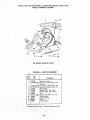
SAW
TABLE
DADO
L_W
The arbor on the saw, is only long enough so that the
widest cut that can be made is 13/16" wide.
It is not necessary to install the outside loose collar before
screwing 'on the arbor nut. Make sure the arbor nut is tight,
ALWAYS
USE DADO
INSERT
LISTED
UNDER
RECOMMENDED ACCESSORIES.
AR BOR NUT
When using the dadoing head it will be necessary to remove
the Blade Guard and Spreader. USE CAUTION,
ALWAYS
REPLACE
THE
BLADE GUARD
AND
SPREADER WHEN YOU ARE FINISHED DADOING.
MOLDING CUTTING
Instructions for operating the Molding Head are contained
in a booklet furnished with the Molding Head.
l
INSERT
/
DADO
LOOSE
HEAD
COLLAR
When using the molding head it will be necessary to remove
the Blade Guard and Spreader. USE CAUTION.
ALWAYS
REPLACE
THE
BLADE GUARD AND
SPREADER WHEN YOU ARE FINISHED MOLDING.
ADJUSTMENTS
(Not previously noted)
LOCK
WARNING:
FOR YOUR OWN SAFETY, TURN SWITCH
"OFF"
AND REMOVE PLUG FROM POWER SOURCE
OUTLET BEFORE MAKING ANY ADJUSTMENTS.
MITER
BAR
KNOB
_
'l_
1,
STOP
PIN
GAUGE
NOTE: The holes for the stop pin and the graduations are
manu-[actured to very close tolerances which provide
accuracy for average woodworking, in some caseswhere
extreme accuracy is required, when making angle cuts, for
example, make a trial cut and then recheck it.
If necessary, the miter gauge head can be swiveled slightly
to compensate for any inaccuracy.
1. Loosen the "knob" and pull "stop pin" OUT.
2. Swivel the head ... position it at "0 °" ... push the
stop pin IN ... lock the handle.
3. The HEAD should be square with the Bar and the
pointer should point to "0". Readjust the pointer if
necessary.
4. If the head is not square with the bar, adjustments are
required.
A. Loosen the "knob" (1) and the "two screws" (2)
B. Position the HEAD square with the BAR using a
combination square.
C. PUSH the STOP PIN into the slot in the head at
"0"...
push the pin into the slot and twist it. Lock
the knob.
D. Recheck with the square. If the head is still not
square, loosen the screws (2) and readjust the
INDICATOR BLOCK.
E. With the head square with the bar and the pin
pushed into the slot, adjust the pointer (3) to point
tO "0".
F. The miter gauge head must rest on top of the bar
without being able to move up and down ... yet it
must swivel freely.
G. The swiveling movement of the head can be
SQUARE
I/8
IN.
_
INDICATOR
BLOCK
SETSCREW
WRENCH
2 "==_
adjusted by tightening or loosening the setscrew (4)
... using the 1/8 in. setscrew wrench.
NOTE: The setscrew is located inside of the head.
To reach it, swivel the head to 60 degrees and turn
the miter gauge upside down.
HEELING ADJUSTMENT or PARALLELISM
OF SAWBLADE TO MITER GAUGE GROOVE
While cutting, the material must move in a straight line
PARALLEL
to the SAWBLADE -.- therefore both the
miter gauge GROOVE
and the RIP FENCE must be
PARALLEL to the SAWBLADE.
If the sawblade IS NOT parallel to the miter gaugegroove,
the blade will bind at one end of the cut. (This is known as
"HEELING").
To check for parallelism:
WARNING - FOR YOUR OWN SAFETY, TURN SWITCH
"OFF"
AND REMOVE PLUG FROM POWER SOURCE
OUTLET.
1. Raise blade all the way up... raise blade guard.
2. Mark as "x" on one of the teeth which is SET (bent) to
the LE FT.
3. Place the head of a combination square in the
GROOVE ... adjust blade of square so that it just
touches the tip of of the MARKED tooth.
4. Move square to REAR, rotate blade to seeif MARKED
tooth again touches blade of square5. If tooth touches square the same amount at FRONT
and REAR ... sawblade is PARALLEL to MITER
GAUGE GROOVE.
23
If tooth
does not
underneath
PARALLEL
NOTE:
touch
Front
must
be
to GROOVE.
and Rear...
adjusted
Make sure TI LT CLAMP
to
KNOB
the mechanism
make
Lay the saw on its LEFTSIDE.
2.
Loosen
He×. Head screw "A"
between
turn, using a 5/8 in, socket wrench with
3.
Tilt
4.
Place saw in upright
5.
Remove
6.
Reach inside
"C" and "D"
blade..,
tilt
the motor
blade to 90 °.
all the way down.
of the insert opening
and
1/4 to 1/2 turn, using a 5/8
sawblade
1/4 and 1/2
an extension.
screw "B".
position..,
lower
blade
is tightened.
1.
blade to 45 ° and loosen
the
loosen screws
in. wrench.
7.
Replace
8.
Grasp spreader bar at rear of saw and move
•.. recheck blade alignment
with square.
and raise it all the way up.
9.
When blade is PARALLEL
"C" and "D".
10. Lay saw on its LEFT
"B",
SIDE
to groove..,
and tighten
tighten
SCREW "C
screws
screws "A"
BLADE TI LT, OR SQUARENESS
OF BLADE TO TABLE
45 ° (BEVEL) STOP COLLARS.
When the bevel pointer is pointing directly to the "O" mark
on the bevel scale, the sawblade should make a SQUARE
cut 90 ° to the table.
To check for SQUARENESS:
WARNING:
FOR YOUR OWN SAFETY, TURN SWITCH
"OFF" AND REMOVE PLUG FROM POWER SOURCE
OUTLET.
1. Raise blade all the way UP ... raise blade guard.
2. TILT blade a few degrees to the LEFT ... nowtilt
blade back to the RIGHT as far as it will go.
3.
!
jj
and
l
90 ° (SQUARE)and
\\\
i
sideways
Place ACCURATE
square against blade. Make sure
square is not touching the TIP of one of the saw
TEETH.
24
\
"o"
If bladeISSQUARE
totable;
A. Check
pointer
If POINTER
DOESNOTpointto the "0""markonthe
bevelscale;
B. Loosen
screwandadjustpointer... usingmedium
screwdriver.
/
If blade
must
is NOT
SQUARE
to table..,
the 90 ° stop
screw
to four
turns
using
check
once
/
be ADJUSTED.
1.
Unscrew
90 ° STOP SCREW
3/16 in. setscrew wrench.
2.
Tilt
3.
Screw
blade so that
g0 ° stop
it is square with
screw
again for squareness
4.
Check
5.
Tilt
POINTER...
6.
same way.
Check POINTER.
blade
If POINTER
bevel scale.
A.
to
IN until
and
NOT
Loosen
the
POINTE
R points
two
adjust
point
table.
it stops..,
and readjust
readjust,
45 °
DOES
three
screw, if necessary.
if necessary.
45 ° STOP
to the
screws and adjust
SCREW
45 ° mark
the
on
the
bevel scale until
to 45 ° mark on scale.
HEAD
COMBINATION
25
OF
SQUARE
POI NTER
EL_v_
ELEVATION
When correctly
adjusted,
the elevation
mechanism
securely when the ELEVATION
LOCK
one inch from the front of the saw.
After
extended
use, the
NUT may wear, which
1. Tilt blade to 45 ° .
2.
Remove retaining
3.
Move
LOCK
ELEVATION
will
cause
lock
a 3/8
in the
to
If retaining
screw is in last hole
WRENCH
off of LOCK
NUT
rotating
it CLOCKWISE.
SCREW
to accumulate
Frequently
and Pitch
clean your
Remover.
cutting
of
only
hole.
#le
arrow
enough
as shown,
rift
and
reposition
to
L{)CK
Jt r_v
/
_:LLVAT [Offd
_OC t<. NUT
array
tools
with
\
the, saw.
accumulate
_ns,de
Craftsman
Gum
A coat of automobile-type
wax applied
to the table and the
rip fence guide bar will help to keep
the surfaces dear_ and
allow workpteces
and the fence to slide
more
freely.
If the power cord is worn or cut,
have it replaced immediately.
Make
always
1.
2.
sure
the
teeth
of the
or
damaged
in any way,
ANTIKlCKBACK
pawls
are
teeth
are
sharp. To sharpen:
Remove blade guard.
Rotate pawl toward rear of
spreader
so that
above top of spreader.
3.
Hold spreader with
of workbench.
4.
Using
teeth.
a small
left hand
round
file
and
p|ace
(Smooth
. .._._
............
,......
in, wrench.
inside
Frequently
blow out any dust that
the saw cabinet and the motor.
....
and
WARNING:
FOR YOUR OWN SAFETY.
TURN
SWITCH
"OFF"
AND REMOVE
PLUG
FROM
POWER
SOURCE
OUTLET
BEFORE
MAINTAINING
OR
LUBRICATING
YOUR SAW.
sawdust
SCRE',_
_:_a[>pro×.
MAINTENANCE
Do not allow
..CCK
sli_.
direction
(this will tighten
the LOCK
NUT,
replace the retaining screw in the next
4.
""i s'>"_"_`
_ tock_
KNO!_
LOCK
the
screw, using
WRENCH
T_QN
LOCK
pawl
Cut)
over corne_
sharpen
the
_6
\
\
/
,
RE]A flt'"J!NO
SC q[: Y;i
LOCK
WR_:NCH
,_
ELEVATION
LOCK KNOB
LUBRICATION
The saw motor
bearings have been packed at the factory
with proper
lubricant
and require no additional
lubrication.
1.
Lay the saw on its LEFT
2.
Clean the following
parts with
Pitch Remover;
BEVEL
GEARS,
AND TEETH,
TILT WORM AND
SIDE.
Lubricate
these parts and other bearing
with SAE No. 20 or No. 30 engine oil.
The following
parts should be oiled
No. 20 or No. 30 engine oil.
Bearing
points
in guard
assembly
GUARD
Craftsman
Gum
and
ELEVATION
WORM
TEETH.
points
occasionally
indicated,
with
SAE
and rip fence.
_l"
"_
j
WORM
TEETH
RECOMMENDED
ITEM
Retractable
CAT.
Caster Set
7 In. Molding
Head Set
7 In. Molding
Head Set ...........
.........................
Head
7 In. Molding
Dado/Molding
Dia. Molding
Insert for 7 in.
or Dado Head
...........
CAT.
7 In. Dia. Dado
Blade
Head
Stabilizers
Sanding
Wheel
9-3214
M iter-G auge Stop
Miter-Gauge
9-29997
9-2480
9-2481
..............
9-3263
Taper
Jig
Universal
.......................
...........................
9-3218
................
.............
. ...........
Work Light
.................
Work Light
...................
7 In. Dia. Adjustable
Oado Head
TEETH
ITEM
NO.
• 9-3217
.....................
POINTS
ACCESSORIES
.. 9-22208
...................
AND
BEARING
Rods
9-29924
Clamp
9-29928
..............................
Power Took Know How Handbook
Table Saw
.............................
27
9-22723
.....................
.................................
Jig
9-3257
9.4952
...........................
Hold-Down
NO,
..............
9-3233
9-3231
9,2918
TROUBLE
WARNING: FOR YOUR OWN SAFETY,
OUTLET BEFORE TROUBLESHOOTING.
TURN
SWITCH "OFF"
TROUBLE
TROUBLE
'
PROBABLE
SHOOTING
AND ALWAYS
SHOOTING
REMOVE PLUG FROM POWER SOURCE
-- GENERAL
CAUSE
REMEDY
i
i
Excessivevibration,
balance.
i
Cannot make square
cut when crosscutting,
Cut binds, burns or
stalls motor when
=
1. D iscard Blade and use a different blade.
2. Failure to tighten
Tilt Lock Knob.
2. See "Getting To Know Your Saw"
section, "Tilt Lock Knob'"
1. Miter gauge not adjusted
properly.
1. See "Adjustments"
1. Dull blade with improper
tooth set.
1. Sharpen or replace blade.
2. See "Adjustments"
section, "Heeling Adjustments..
3. Make sure concave or hollow side is facing
3. Warped board.
"down,"
'
,
Cut not true at 90 °
"
section "lVliter Gauge".
"
feed slowly.
4. Rip fence not parallel to
blade.
4. See "Assembly"
section, "Aligning
5. Spreader out of
5. See "Assembly"
section, "Installing
alignment
1. Stop screws not properly
B lade Guard."
1. See "Adjustments"
Rip Fence"
section, "Blade Tilt, or Squareness
B lade to Table."
,
1. Tilt lock knob not
1 See "Getting To Know Your Saw" section,
"Tilt Lock Knob."
I
2. Gearsworms and
2. See "Lubrication"
section.
teeth clogged with
sawdust.
TROUBLE
SHOOTING
NOTE: Motors used on wood-working tools are particularly
susceptible to the accumulation of sawdust and wood chips
TROUBLE
PROBABLE
Excessive noise.
and should be blown out or "vacuumed"
frequently
prevent interference with normal motor ventilation.
CAUSE
REMEDY
1. Motor.
'
•
Motor fails to develop
i
full power, (Power
"
output of motor decreases
-- MOTOR
1. Circuit overloaded with
I. Have motor checked by qualified service
technician. Repair service is available at
your nearest Sears store.
1: Do not use other appliances or motors on
lights, appliances and
I
same circuit when usingthe saw.
other motors,
rapidly with decrease in
voltage at motor terminals.
2. Undersize wires or circuit
2. Increase wire sizes, or reduce length of wiring.
too long.
See "Motor
of 10% in voltage causes
a reduction of 19% in
3. General overloading of
maximum power output
3. Request a voltage check from the power company.
power company
f
of 20% in voltage causes
Specification and Electrical
Requirements" section.
!
a reduction of 36% in
I
maximum power output.) _
I
facilities. (In some
sections of the
country, demand for
electrical power may
exceed the capacity
of existing generating
i
breakers in power line.
28
to
TROUBLE
TROUBLE
Motor
starts slowly
or fails to come up
to full
Motor
speed.
overheats.
SHOOTING
-- MOTOR
(Continued)
PROBABLE CAUSE
REMEDY
1. Low voltage will not
1. Request voltage check from the power company.
trip relay.
2. Windings burned out
2. Have motor repaired or replaced.
or open.
3. Starting relay not
3. Have relay replaced.
operating.
1. Motor overloaded.
1. Feed work slower into blade.
2. Improper cooling. (Air
circulation restricted
2. Clean out sawdust to provide normal air
circulation through motor.
See "Maintenance and Lubrication" section.
through motor due to
sawdust, accumulating
inside of saw).
Starting relay in
motor will not
1. Burned relay contacts
(due to extended
1. Have relay replaced
from
and request
a voltage
check
the power company.
hold-in periods caused
operate.
by low line voltage, etc.)
2. Shorted capacitor
2. Test capacitor and replace
(when equipped)
3. Loose or broken
if defective.
3. Have wiring checked and repaired.
connections.
Motor stalls
(resulting in blown
fuses or tripped
circu it breakers).
1. Have relay replaced.
1. Starting relay not
operating.
2. Voltage too low to permit
2. Request voltage
check from
the power
company.
motor to reach operating
speed.
3. Fuses or circuit breakers
3. Install proper size fuses or circuit breakers.
do not have sufficient
Frequent
opening of
fuses or circuit
breakers.
capacity.
1. Motor overloaded.
1. Feed work slower into blade.
2. Install proper size fuses or circuit breakers.
2. Fuses or circuit breakers
do not have sufficient
capacity.
3. Starting
operating
relay not
3. Have relay replaced.
(motor does
not reach speed).
29
PARTS LIST FOR CRAFTSMAN
12-INCH MOTORIZED
MODEL NUMBER 113.24250
8
4
6
9
10
7
t
31
/
J
I
23
J
_
_o
28
Figure
I
TABLE
SAW
PARTS LIST FOR CRAFTSMAN 12-INCH MOTORIZED
MODEL NUMBER 113.24250
TABLE
SAW
Always order by Part Number -- not by Key Number
FIGURE
Key
No.
1 PARTS LIST
i
Part
No.
Description
I
Key
No.
Part
No.
Description
i
i
1
4
5
6
STD 541025
STD 551225
STD 522506
62594
STD 523110
62541
7
8
9
62718
STD 501102
62731
10
tl
12
13
60313
133645
62584
62493
60122
STD 541031
STD 551231
62539
14
15
16
17
*Nut, Hex 1/4-20
* Lockwasher, External 1/4
*Screw, Hex Hd. 1/4-20 x 5/8
18
19
62710
62709
Guard Assembly (See Figure 7)
*Screw, Hex Hd. 5/16-18 x 1
Bar, Fence Rear
Clip, Retaining
*Screw, Locking Set 10-32 x 3/16
Insert Assembly
(Includes Key No. 7 & 8)
Nut, Self-threading
Screw, Flat Hd. 10-32 x 1
20
STD 523115
21
22
23
24
25
26
27
28
29
30
31
62705
62725
STD 551237
454896
STD 551243
60127
30613
STD 600803
STD 523112
62589
62704
62596
62732
Rod, Separation
Insert, Exact-l-Cut
*Screw, Soc. Set 3/8-16 x 7/8
*Nut, Hex 5/16-18
* Lockwasher, External 5/16
Spacer, Fence Guide Bar
*Standard
-
Hardware
Item -
May be Purchased
Tape,
Fence
Bar Assembly,
Fence Guide
(Includes
Key No. 18)
Locally.
*Screw,
Hex Hd. 5/16-18
Fence Assembly,
Table,
3)
Saw
* Lockwasher,
Screw,
External
3/8
Hex Hd. 3/8-16
* Lockwasher,
Bolt,
x 1-1/2
Rip (See Figure
x 1/2
External
7/16
Hex Hd. 7/16-14
x 1
Clamp,
Cord
*Screw,
Pan Hd. Ty.
*Screw,
Hex Hd.
Extension,
Table
Gauge Assembly,
'q'"
5/16-18
Manual
x 1-!/4
(See Figure
Miter
(Not
8)
(See Figure
Bag of Loose Parts (Not
Owner's
8-32 x 3/8
Illustrated)
Illustrated)
6)
PARTS LIST FUR CRAFTSMAN
12-INCH MU I UHI.,'_U
MODEL NUMBER 113,24250
I A_L_
_,vv
3
I
I
/
\
\
\
9
10
11
\
i_i
44
_
2_
2e
,
_\
i'T\
;.
64
_..j72
63
39
45
'-/ ,, ,,
'_ I
l
/.
39
71
so
49
,/
\
69
7O
48
PARTS LIST FOR CRAFTSMAN
12-INCH MOTORIZED
MODEL NUMBER 113.24250
FIGURE
Key I
6
7
9
10
11
12
13
14
15
16
17
W
62459
30494
60177
6362
3450
63062
STD 600803
30613
STD 582075
62342
62340
62339
STD 551231
STD 523106
STD 503705
18
62093
62330
STD 503103
19
20
21
22
23
24
25
26
27
28
29
30
31
32
33
34
35
36
37
38
39
62098
62100
STD 551012
STD 601103
62587
60204
STD 571812
62585
62218
STD 551050
62094
STD 581031
62097
62331
63011
62101
62099
62086
STD 571810
62090
STD 551225
Key
No.
Description
4O
41
42
43
44
45
46
47
48
49
Motor Assembly (See Fig. 4)
Collar
+Blade, Saw, 12" Chisel Tooth
Nut, Saw Arbor
Wrench, Arbor
Wrench, Shaft
*Screw, Self-Tapping,
No. 8-32 x 3/8", Pan Hd.
Clamp, Cord
Ring, Retaining, 3/4"
Washer, 25/32 x 1-3/8 x 1/8"
Pin, Motor Pivot
Support, Motor
* Lockwasher. 5/16"
*Screw, Hex Hd. 5/16-18 x 5/8"
*Screw, Set, 3/8-16 x 5/8".
Hex. Soc. Flat Pt.
Screw, Stop
Cradle
*Screw, Set, 5/16-18 x 3/8",
Hex. Soc, Cup Pt.
Trunnion, Back
Bolt, Sq. Hd. 3/8-16 x 7
*Washer, 7/32 x 1 x 1/i6"
*Screw, Pan Hd. Type "T'" 10-32 x 3/8"
Support, Spreader
Screw, Thumb 5/16-18 x 1
*Pin, Roll, 3/16 x 1-1/4"
Rod, Spreader
Bar, Spreader
*Washer, 17/32 x 1-1/4 x 3/32"
Screw, Lock
Ring, Retaining 5/16
Rod, Lock Screw Push
Knob Assembly, 2-1/4"
Washer, Knob Clamp
Spacer
Trunnion, Front
Collar
*Pin, Roll, 3/16 x 1"
Plate, Bearing
* Lockwasher, 1/4"
SAW
2 PARTS LIST
Part
No.
TABLE
5O
51
52
53
54
55
56
57
58
59
60
61
62
63
64
65
66
[
67
68
69
70
71
72
73
74
i
75
i
Part
No.
STD 522506
62332
62726
STD 511002
62727
62689
STD 551210
STD 511107
STD 610805
62730
62729
60354
STD 502503
62356
62222
STD 582087
62221
6O159
62223
STD 541031
62220
60160
62096
STD 522503
62095
62460
STD 522505
STD 541250
803835
62113
62728
STD 541025
30504
37837
30505
37836
Description
*Screw, Hex, Hd. 1/4-20 x 5/8"
Knob Assembly, Pull
Indicator, Tilt
*Screw, Pan Hd.
Worm, Elevating
Handwheel Assembly
* Lockwasher, External No. 10
*Screw, Pan Hd. 10-32 x 3/4
*Screw Type "AB" Pan Hd. No. 8 x 1/2"
Scale, Adjustable Bevel
Panel, Front
Nut, Speed No. 8
*Screw, Set, 1/4-20 x 5/16",
Hex. Soc. Cup Pt.
Crank Assembly, Tilt
Shaft, Tilt
* Ring, Retaining 7/8
$Gear, Miter
Washer, Spacing, 1-1/2 x .630 x .005
(Used to adjust end-play after installing
Key No. 56, supplied 5 in a package)
Worm, Tilt
*Nut, Hex., 5/16-18
_:Gear, Miter
Washer, Spacing, 1-1/2 x .875 x .005
(Used to adjust end-play after installing
Key No. 60, Supplied 5 in a package)
Wrench, Lock
*Screw, Hex. Hd., 1/4-20 x 3/8"
Nut, Height Lock
Leg, Base
*Screw, Hex. Hd., 1/4-20 x 1/2"
*Nut, Hex., !/2-13
Foot, Leveling
Stiffener, Leg
Base, Saw
*Nut, Hex 1/4-20
*Wrench, Hex "L", 3/16"
*Wrench, Hex "L", 5/32"
*Wrench, Hex "L", 1/8"
*Wrench, Hex "L", 3/32"
_Standard Hardware Item - May be Purchased Locally,
_:When replacing
gear (Key 56), use spacing washers
(Key
57) to adjust
end-play.
_Stock Item -- May be secured through the hardware departments
of rr!o_t Sears Retail Stores or Catalog Order Houses:
_lNhen replacing gear (Key 60), use spacing washers (Key 61) to adjust end-play,
PARTS LIST FOR CRAFTSMAN
"12-1NCH MOTORIZED
MODEL NUMBER 113.24250
TABLE SAW
1o
8
I
13
FIGURE
Key
No.
-
3 - 62705 FENCE ASSEMBLY
Part
No.
Description
1
2
3
4
5
6
7
8
9
10
11
12
62705
62693
62692
STD 551031
62711
60049
62527
423350
62582
STD 600805
62528
' 62529
62531
13
14
15
62583
62533
STD 55121O
*Standard
Hardware
Item
Fence Assembly, R ip
Plug, Button
Knob (Includes Key No. 1)
*Washer, 21/64 x 1/2 × 1/32
Indicator, Fence
Screw, Pan Hd. Type "1- 4-40 x 3/16
Head. Fence
Screws, Serns3/8-16 x 1/2
Channel, Fence
*Screw, Pan Hd. Type "'T" 8-32 x 1/2
Spring, Fence Lock
Lock, Rear Fence
Roller, Rear Fence
Rod, Fence Lock
Spring, Head Alignment (Includes ##17)
* Lockwasher External No. 10
* Screw, p an Hd. Type "'A"No.
lOx 1/2
- May be Purchased
Locally.
]!
PARTS
LISTFORCRAFrSMAN
12-INCH
MOTORIZED
TABLE
SAW
MODEL
NUMBER
113.24250
!
2
3
4
TO SWITCH
O ANY ATTEMPT TO REPAIR THIS MOTOR MAY
CREATE A HAZARD UNLESS REPAIR IS DONE
BY QUALI FI ED SERVICE TECHNICIAN.
REPAIR SERVICE
IS AVAILABLE
AT YOUR
NEAREST SEARS STORE.
FIGURE
Key
No.
1
2
3
4
4 -
62459
Part
No.
MOTOR
ASSEMBLY
Description
62459
o Complete Motor Assembly
62467
Box Assembly, Control (w/Nameplate)
STD 600603 *Screw, Self-Tapping, No.6-32 x 3/8",
Pan Hd., Slotted
STD 600803 *Screw, Self-Tapping, No.8-32 x 5/16",
' Pan Hd., Slotted
Cover, Brake
*Standard Hardware Item - May be Purchased Locally.
35
PARTS LIST FOR CRAFTSMAN
12-INCH MOTORIZED
MODEL NUMBER 113.24250
TABLE SAW
1
2
12 !!,-
11
il
10
t_t < _
SEE WILING
FIGURE
Key
No.
DIAGRAM,
62466
STD 601103
3
4
5
6
7
8
9
10
11
STD 551210
STD 541110
62500
37838
60287
60256
STD 611005
37818
62613
13
63467
7
PAGE 5
5 -- SWITCH ASSEMBLY
Part
No.
1
2
_.e.....,.---
/
Description
Bracket, Housing
Screw, Type 23, 10-32 x 3/8",
Pan Hd.
Lockwasher, External No. 10
Nut, Hex., 10-32 x 3/8 × 1/8"
Box, Switch
Washer, 5/8 × 7/8 × 1/64"
Screw, Nylon, 6-32 x 5/16"
Key
Screw, Type B No. 10 x 1/2"
Relief, Strain
Cord with Plug
Switch
Cap, Insulator
*Standard Hardware Item - May be Purchased Locally.
36
PARTS LIST FOR CRAFTSMAN 12-INCH MOTORIZED
MODEL NUMBER 113.24250
TABLE SAW
7
8
/
/
\
\
13
12
I
10
FIGURE 6 -- 62704 MITER
Key
No.
1
2
3
4
5
6
7
8
9
Pa_
No.
37896
9417295
10
62230
11
12
13
14
STD541231
*Standard
Hardware
62225
62383
60286
I
GAUGE ASSEMBLY
Description
62704
62693
62692
STD 551031
37893
STD 510803
135
i 37895
11
+Gauge Assembly,
Miter
Plug, Button
Knob,
Miter Gauge (Includes
*Washer,
Plain, 21/64
Key No. 1)
x 1 x 1/16"
Gauge, Miter
*Screw,
Pan Hd. 8-32 x 5/16"
Indicator
,
,
Block, Miter Gauge Indicator
Pin, Miter Gauge Stop
*Screw, Pan Hd., w/Lockwasher,
8-32 x 5/8"
I Rod Assembly, Miter Gauge,
Consisting of Items 11, 12, 13
*Nut Hex., 5/16-18
Stud, Clamp
Stud, Pivot
Screw, Locking Set, 1/4-20 x 3/8"
Item -- May be Purchased
Locally.
+Stock Item - May be secured through
the Hardware
most Sears Retail Stores or Catalog Order Houses.
37
Departments
of
PARTS LIST FOR CRAFTSMAN
12-INCH MOTORIZED
MODEL NUMBER 113.24250
TABLE
SAW
i
8
7
10
/
6
11
I
6
9
FIGURE
Key
No.
1
2
3
4
5
6
7
8
9
10
11
7 - 62594 GUARD
Part
No.
i
62594
60297
62391
62395
62389
62390
STD 551025
• 62520
62396
62595
62410
STD 571810
62519
.
ASSEMBLY
Description
Guard Assembly, Saw
Nut, Push
Pin 1/4 x 1-1/2"
Support, Guard
Guard, Saw
,,
Pin, 1/4 x 1-3/4
*Washer, 17/64 x 5/8x 1/16"
. Spacer, Pawl
Pawl
Spreader, Assembly Blade
. Pin, 1/4x 1"
*Pin, Roll, 3/16x 15/16"
i Spring, Pawl
'
!
* Standard Hardware Item - May Be Purchased Locally.
38
1
PARTS LiST FOR CRAFTSMAN 12-INCH MOTORIZED
MODE L NUMBER 113.24250
2
!
7
7
4
FIGURE 8 - 62589 TABLE
Key
No.
-
-
Part
No.
1
62589
60323
3
4
5
6
7
62590
62549
62548
STD 541025
STD 551225
62550
EXTENSION
Description
Extension Assembly, Complete
Screw, Serrated Truss Hd.,
1/4-20 x 1"
Extension
Bracket, Corner Support No. 2
Bracket, Corner Support No. 1
*Nut, Hex 1/4-20
*Lockwasher, Ext. 1/4
Bracket, Corner Stiffener
*Standard Hardware Item - May be Purchased Locally.
39
TABLE SAW
12 INCH
MOTORIZED
TAB LE SAW
SERVICE
Now that you have purchased your 12-inch table saw, should a
need ever exist for repair parts or service, simply contact any
Sears Service Center and most Sears, Roebuck and Co. stori_.
Be sure to provide all pertinent facts when you call or visit.
The model number of your 12-inch table saw will be found
plate attached to your saw, at the rear of the base.
HOW TO ORDER
REPAIR PARTS
WHEN ORDERING
REPAIR
FOLLOWING
INFORMATION:
PARTS,
ALWAYS
GIVE
on a
THE
I
PART NUMBER
PART DESCRIPTION
MODEL NUMBER
113.24250
NAME OF ITEM
12-INCH TABLE SAW
All parts listed may be ordered from any Sears Service Center
and most Sears stores. If the parts you need are not stocked
locally, your order will be electronically transmitted to a Sears
Repair Parts Distribution Center for handling.
Sold by SEARS,
Part No. 62732
ROEBUCK
AND
Form
CO., Chicago,
No. SP4320-1
IL. 60684
Printed
U.S.A.
in U.S.A,
8/78