1
Owner's Manual
£RAFTIMRN
3.75 HP
14 INCH TINE WIDTH
REAR TINE WITH COUNTER
ROTATING TINES-
TILLER
Model No.
917.293180
• Safety
• Assembly
• Operation
• Maintenance
• Espa_ol
• Repair Parts
CAUTION:
Read and follow all Safety
Rules and Instructions before
operating this equipment.
Sears, Roebuck and Co., Hoffman Estates, II 60179
Visit our Craftsman website:www.sears.com/craftsman
Warranty ................................................
Safety Rules ..........................................
Product Sprcifications ...........................
Assembly ..............................................
Operation .......................................
3&
LIMITED ONE YEAR WARRANTY
Manintenance
.....................................
13
Service and Adjustments .................... 15
Storage ........................................
3 & 19
Troubleshooting
..................................
20
Illustrated Parts List ............................. 42
Parts Ordering ...................... Back Cover
2
2
4
5
8
ON CRAFTSMAN
TILLER
For one (1) year from date of purchase, when this Craftsman Tiller is maintained,
lubricated, and tuned up according to the operating and maintenance instructions in the
owner's manual, Sears will repair free of charge any defect in material or workmanship.
This Warranty does not cover:
• Expendable items which become worn during normal use, such as tines, spark plugs,
air cleaners and belts.
• Repairs necessary because of operator abuse or negligence, including bent crankshafts and the failure to maintain the equipment according to the instructions contained in the owner's manual.
• If this Craftsman Tiller is used for commercial or rental purposes, this Warranty applies
for only thirty (30) days from the date of purchase.
Warranty service is available by returning the craftsman power mower to the nearest
sears service center/department
in the united states. This warranty applies only while
this product is in use in the united states.
This Warranty gives you specific legal rights, and you may also have other rights which
vary from state to state.
SEARS,
ROEBUCKAND
CO., D/817WA,
HOFFMAN
• Disengage all clutches and shift into
neutral before starting the engine
(motor).
• Do not operate the equipment without
wearing adequate outer garments.
Wear footwear that will improve footing
on slippery surfaces.
• Handle fuel with care; it is highly
flammable.
• Use an approved fuel container.
• Never add fuel to a running engine or
hot engine.
• Fill fuel tank outdoors with extreme
care. Never fill fuel tank indoors.
• Replace gasoline cap securely and
clean up spilled fuel before restarting.
• Use extension cords and receptacles
as specified by the manufacturer for all
units with electric drive motors or
electric starting motors.
• Never attempt to make any adjustments while the engine (motor) is
running (except where specifically
recommended by manufacturer).
IMPORTANT: This cutting machine is
capable of amputating hands and feet
and throwing objects. Failure to observe
the following safety instructions could
result in serious injury or death.
TRAINING
• Read the Owner's Manual carefully. Be
thoroughly familiar with the controls and
the proper use of the equipment. Know
how to stop the unit and disengage the
controls quickly.
• Never allow children to operate the
equipment. Never allow adults to
operate the equipment without proper
instruction.
• Keep the area of operation clear of all
persons, particularly small children, and
pets.
PREPARATION
• Thoroughly inspect the area where the
equipment is to be used and remove all
foreign objects.
ESTATES, IL 60179
2
OPERATION
MAINTENANCE
AND STORAGE
• Do not put hands or feet near or under
rotating parts.
• Exercise extreme caution when
operating on or crossing gravel drives,
walks, or roads. Stay alert for hidden
hazards or traffic. Do not carry passengers.
• After striking a foreign object, stop the
engine (motor), remove the wire from
the spark plug, thoroughly inspect the
tiller for any damage, and repair the
damage before restarting and operating the tiller.
• Exercise caution to avoid slipping or
falling.
• If the unit should start to vibrate
abnormally, stop the engine (motor)
and check immediately for the cause.
Vibration is generally a warning of
trouble.
• Stop the engine (motor) when leaving
the operating position.
• Take all possible precautions when
leaving the machine unattended.
Disengage the tines, shift into neutral,
and stop the engine.
• Before cleaning, repairing, or inspecting, shut off the engine and make
certain all moving parts have stopped.
Disconnect the spark plug wire, and
keep the wire away from the plug to
prevent accidental starting. Disconnect
the cord on electric motors.
• Do not run the engine indoors; exhaust
fumes are dangerous.
• Never operate the tiller without proper
guards, plates, or other safety protective devices in place.
• Keep children and pats away.
• Do not overload the machine capacity
by attempting to till too deep at too fast
a rate.
• Never operate the machine at high
speeds on slippery surfaces. Look
behind and use care when backing.
• Never allow bystanders near the unit.
• Use only attachments and accessories
approved by the manufacturer of the
tiller.
• Never operate the tiller without good
visibility or light.
• Be careful when tilling in hard ground.
The tines may catch in the ground and
propel the tiller forward. If this occurs,
let go of the handlebars and do not
restrain the machine.
• Keep machine, attachments, and
accessories in safe working
condition.
• Check shear pins, engine mounting
bolts, and other bolts at frequent
intervals for proper tightness to be
sure the equipment is in safe
working condition.
• Never store the machine with fuel in
the fuel tank inside a building where
ignition sources are present, such
as hot water and space heaters,
clothes dryers, and the like. Allow
the engine to cool before storing in
any enclosure.
• Always refer to the operator's guide
instructions for important details if
the tiller is to be stored for an
extended period.
_,Look for this symbol to point out
important safety precautions. It means
CAUTION!!! BECOME AWARE!!!
YOUR SAFETY IS INVOLVED.
_I,CAUTION: Always disconnect spark
plug wire and place wire where it
cannot contact spark plug in order to
prevent accidental starting when
setting up, transporting, adjusting or
making repairs.
AWARNING"
The engine exhuast
from this product contains chemicals
known to the State of California to
cause cancer, birth defects or other
reproductive harm.
3
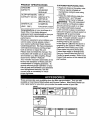
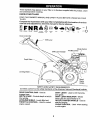
PRODUCT
SPECIFICATIONS
GASOLINE
CAPACITY:
2 QTS
UNLEADED
REGULAR
OIL(API-SF/SG/SH):
SAE 30
CAPACITY: 20 OZ.)
CUSTOMER
• Read and observe the safety rules.
• Follow a regular schedule in
maintaining, caring for and using
your tiller.
• Follow the instructions under the
"Maintenance"
and "Storage"
sections of this Owner's Manual.
AWARNING"
This unit is equipped
with an internal combustion engine
and should not be used on or near
any unimproved forest-covered,
brush-covered or grass covered land
unless the engine's exhaust system is
equipped with a spark arrester
meeting applicable local or state laws
(if any). If a spark arrester is used, it
should be maintained in effective
working order by the operator.
In the state of California the above is
required by law (Section 4442 of the
California Public Resources Code).
Other states may have similar laws.
Federal laws apply on federal lands.
See your Sears Authorized Service
Center for spark arrester. Refer to the
Repair Parts section of this manual for
part number.
(ABOVE 32°F)
SAE 5W-30
SPARK PLUG :
(BELOW 32°F)
CHAMPION
(GAP: .030")
RJ 19LM OR J 19LM
RESPONSIBILITIES
Congratulations
on your purchase of a
Sears Tiller. It has been designed,
engineered and manufactured to give you
the best possible dependability and
performance.
Should you experience any problems you
cannot easily remedy, please contact
your nearest authorized Sears Service
Center/Department.
We have competent,
well-trained technicians and the proper
tools to service or repair this unit.
Please read and retain this manual. The
instructions will enable you to assemble
and maintain your tiller properly. Always
observe the "SAFETY RULES".
Your new tiller has been assembled at the
factory with exception of those parts left
unassembled for shipping purposes. To
ensure safe and proper operation of your
tiller all parts and hardware you assemble
must be tightened securely. Use the
correct tools as necessary to insure
proper tightness.
These accessories were available when the tiller was purchased. They are also
available at most Sears Retail outlets and Service Centers. Most Sears Stores can
order repair parts for you when you provide the model number of your tiller.
ENGINE
TILLER PERFORMANCE
TILLER MAINTENANCE
BELT
TINES
SHEAR PIN
4
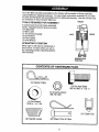
HAIRPIN CLIP
Your new tiller has been assembled at the factory with exception of those parts left
unassembled for shipping purposes. To ensure safe and proper operation of your tiller
all parts and hardware you assemble must be tightened securely. Use the correct tools
as necessary to insure proper tightness.
FRONT
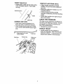
TOOLS REQUIRED FOR ASSEMBLY
A socket wrench set will make assembly
easier. Standard wrench sizes are listed.
(1) Utility knife
(1) Wire cutter
(1) Tire pressure guage
(1) Screwdriver
(1) Pair of pliers
(1) 9/16 Wrench
OPERATOR'S
RIGHT
LEFT
POSITION
When right or left hand is mentioned in
this manual, it means when you are in
the operating position (standing behind
tiller handles).
OPERATOR'S
POSITION
CONTENTS
OF HARDWARE PACK
I
(1) Hairpin Clips
G
(3) Fin Hex Bolts
3/8-16 UNC x 1 Gr. 5
(1) CrownLocknut
3/8-16
UNC
(1) Flat Washer
13/32 x 1 x 11 Ga.
t
/llllll//
(2) Handle
Locks
°L
(2) Shear
Pins & Clips
5
(1) Cable
Clip
UNPACKING CARTON
_.CAUTION:
Be careful of exposed
staples when handling or disposing of
cartoning material.
IMPORTANT:When
unpacking and
assembling tiller, be careful not to stretch
or kink cables.
• While holding handle assembly, cut
cable ties securing handle assembly to
top frame. Let handle assembly rest on
tiller.
• Remove top frame of carton.
• Slowly ease handle assembly up and
place on top of carton.
• Cut down right hand front and right
hand rear corners of carton, lay side
carton wall down.
• Remove packing material lrom handle
assembly.
• Separate shift rod from handle assembly.
...._:..:'!i:. /
_":::
",JP" Position
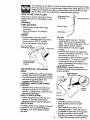
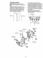
Tightenhex bo_t
_::::_:::=
hold
LoosenHex Bol_
to Move
/f_
.*_
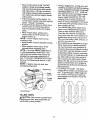
Insert second hex bolt in front part of
plate and tighten.
Cut down remaining corners of carton
and lay panels flat.
Lower the handle assembly. Tighten
nut on hex bolt so handle moves with
some resistance. This will allow for
easier adjustment.
Place flat washer on threaded end of
hex bolt.
Insert hex bolt through handle base
and gearcase. Screw in hex bolt just
enough to hold bolt in place.
Insert second handle lock (with teeth
inward) in the slot of the handle base.
Raise handle assembly to highest
position and securely tighten remaining
hex bolt. Leaving handle assembly in
highest position will make it easier to
connect shift rod.
Assembly
INSTALL
;_"
Handle Assembly
HANDLE
• Insert one handle lock (with teeth
facing outward) in gearcase notch.
(Apply grease on smooth side of
handle lock to aid in keeping lock in
place until handle assembly is lowered
into position.)
VIEWED FROM R.H. SIDE OF TILLER
Handle Lock
Slot.._
Flat
Washer
_/
Rear Hex Belt
\
Gearcase Notch
Handle Lock
Hex Bolt
Locknut/_
Handle Base
• Grasp handle assembly. Hold in "up"
position. Be sure handle lock remains
in gearcase notch. Slide handle
assembly into position.
• Rotate handle assembly down. Insert
rear hex bolt first, with head of bolt on
L.H. side of tiller and loosely assemble
Iocknut.
6
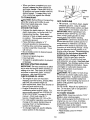
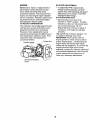
INSERT CABLE CLIP
REMOVE TILLER FROM CRATE
• Insert plastic cable clip into hole on the
back of handle column. Push cable
into clip.
• Adjust handle assemby to lowest
position. Be sure hex bolt is tightened
securely.
• Make sure shift lever indicator is in "N"
(neutral) position.
• Tilt tiller forward by lifting handle.
Separate cardboard cover from levelin!
shield.
Handle Column
• Rotate tiller handle to the right and pull
tiller out of carton.
CHECK TIRE PRESSURE
Cable Clip
The tires on your unit were overinflated at
the factory for shipping purposes, Correc
and equal tire pressure is important for
best tilling performance.
• Reduce tire pressure to 20 PSI.
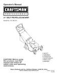
CONNECT SHIFT ROD
• Insert end of shift rod farthest from
bend into hole of shift lever indicator.
• Insert hairpin clip through hole of shift
rod to secure with bend of clip on right
side.
[J-"_-Attach this End To shift
"_'Shift
HANDLE
• Handle height may be adjusted to
better suit operator. (See "TO ADJUST
HANDLE HEIGHT" in the Service and
Adjustments section of this manual).
Rod
Lever Indicator
Shift Rod
Hairpin Clip
HEIGHT
Shift Lever
Indicator
7
These symbols may appear on your Tiller or in literature supplied with the product. Learn
and understand their meeting.
KNOW YOUR TILLER
READ THIS OWNER'S
TILLER.
MANUALAND
SAFETY
RULES BEFORE OPERATING
YOUR
Compare the illustrations with your tiller to familiarize with the location of various
controls and adjustments, Save this manual for future reference.
TILLING
FORWARD
NEUTRAL
REVERSE
CAUTION
OR WAANING
ENGINE
ON
ENGINE
FAST
SLOW
CHOKE
FUEL
OIL
srop
V
OFF
Drive Control Bar
Shift Lever
Shift Lever Indicator
Choke Control
Throttle Control
Depth Stake
Leveling Shield
Recoil
Starter
Handle
MEETS ANSI SAFETY REQUIREMENTS
Our tillers conform to the safety standards of the American National Standards
DRIVE CONTROL BAR - Used to
engage tines.
DEPTH STAKE - Controls depth at which
tilter will dig.
LEVELING SHIELD - Levels tilled soil.
THROTTLE CONTROL - Used to control
Institute.
SHIFT LEVER - Used to shift transmission gears.
SHIFT LEVER INDICATOR - Shows
which gear the transmission is in.
RECOIL STARTER HANDLE - Used to
start the engine,
CHOKE CONTROL - Used when starting
a cold engine.
engine speed.
8
The operation of any tiller can result in foreign objects thrown into the eyes
which can result in severe eye damage. Always wear safety glasses or eye
shields before starting your tiller and while tilling. We recommend a wide
vision safety mask over spectacles or standard safety glasses.
HOW TO USE YOUR TILLER
Know how to operate all controls before
adding fuel and oil or attempting to start
engine.
STOPPING
TINES AND DRIVE
• Release drive control bar to stop
movement.
• Move shift lever to "N" (neutral)
position.
ENGINE
• Move throttle control to "STOP"
position. If equipped with stop switch,
move switch to "STOP" position.
• Never use choke to stop engine.
Drive Control Bar
Position
Shift Lever
Drive Control Bar
"DISENGAGED"
Position
TINE OPERATION
DRIVE
- WITH WHEEL
• Always release drive control bar before
moving shift lever into another position.
• Tine movement is achieved by moving
shift lever to (_) till position and
engaging drive control bar.
FORWARD - WHEELS ONLY/TINES
STOPPED
• Release drive control bar and move
shift lever indicator to "F" (forward)
position. Engage drive control bar and
tiller will move forward.
HARD TO SHIFT GEARS
• Briefly engage drive control bar and
release or rock tiller forward and
backward until are able to shift gears.
DEPTH STAKE
The depth stake can be raised or lowered
to allow you more versatile tilling and
cultivating, or to more easily transport
your tiller.
Shallowest'nlling
(Cultivating)
"_"TransportPositior
Deepest Tilling
Depth Stake
TILLING
• Release depth stake pin. Pull the
depth stake up for increased tilling
depth. Place depth stake pin in hole of
depth stake to lock in position.
• Place shift lever indicator in (_)till
position.
• Hold the drive control bar against the
handle to start tilling movement. Tines
and wheels will both turn.
• Move throttle control to "FAST" position
for deep tilling. To cultivate, throttle
control can be set at any desired
speed, depending on how fast or slow
you wish to cultivate.
IMPORTANT: Always release drive
control bar before moving shift lever into
another position.
Depth Stake Pin
"RELEASED" Position
\
"Locked"
Position
TURNING
• Release the drive control bar.
• Move throttle control to =SLOW"
position.
• Place shift lever indicator in "F"
(forward) position. Tines will not turn.
• Lift handle to raise tines out of ground.
• Swing the handle in the opposite
direction you wish to turn, being careful
to keep feet and legs away from tines.
9
• When you have completed your turnaround, release the drive control bar
and lower handle. Place shift lever in
till position and move throttle control to
desired speed. To begin tilling, hold
drive control bar against the handle.
TO TRANSPORT
A_.CAUTION: Before lifting or transporting,
allow tiller engine and muffler to cool.
Disconnect spark plug wire. Drain
gasoline from fuel tank.
AROUND THE YARD
• Release the depth stake pin. Move the
depth stake down to the top hole for
transporting the tiller. Place depth
stake pin in hole of depth stake to lock
in position. This prevents tines from
scuffing the ground.
• Place shift lever indicator in "F"
(forward) position for transporting.
• Hold the drive control bar against the
handle to start tiller movement. Tines
will not turn.
• Move throttle control to desired speed.
AROUND TOWN
• Disconnect spark plug wire.
• Drain fueltank.
• Transport in upright position to prevent
oil leakage.
BEFORE
STARTING
ENGINE
IMPORTANT: Be very careful not to allow
dirt to enter the engine when checking or
adding oil or fuel. Use clean oil and fuel
and store in approved, clean, covered
containers,
use clean fill funnels.
CHECK ENGINE OIL LEVEL
• The engine in your unit has been
shipped, from the factory, already filled
with SAE 30 summer weight oil.
• With engine level, clean area around oil
filler plug and remove plug.
• Engine oil should be to point of
overflowing when engine is level. For
approximate capacity see "PRODUCT
SPECIFICATIONS"
on page 4 of this
manual. All oil must meet A.P.I.
Service Classification SF, SG or SH.
• For cold weather operation you should
change oil for easier starting (See oil
viscosity chart in the Maintenance
section of this manual).
• To change engine oil, see the Maintenance section in this manual.
Oil Level
Oil Filler
Plug
Oil Drai_
Plug
ADD GASOLINE
• Fill fuel tank. Use fresh, clean, regular
unleaded gasoline. (Use of leaded
gasoline will increase carbon and lead
oxide deposits and reduce valve life.)
IMPORTANT: When operating in temperatures below 32°F(0°C), use fresh,
clean, winter grade gasoline to help
insure good cold weather starting.
_I_WARNING: Experience indicates that
alcohol blended fuels (called gasohol or
using ethanol or methanol) can attract
moisture which leads to separation and
formation of acids during storage. Acidic
gas can damage the fuel system of an
engine while in storage. To avo(d engin_
problems, the fuel system should be
emptied before storage of 30 days or
longer. Drain the gas tank, start the
engine and let it run until the fuel lines
and carburetor are empty. Use fresh rue
next season. See Storage section of thi:
manual for additional information. Never
use engine or carburetor cleaner products in the fuel tank or permanent
damage may occur.
_CAUTION:
Fill to within 1/2 inch of top
of fuel tank to prevent spills and to allow
for fuel expansion. If gasoline is acciden.
tally spilled, move machine away from
area of spill. Avoid creating any source a
ignition until gasoline vapors have
disappeared.
Do not overfill. Wipe off any spilled oil or
fuel. Do not store, spill or use gasoline
near an open flame.
TO START ENGINE
_I,CAUTION:
Keep tine control in "OFF"
position when starting engine.
When starting engine for the first time or i
engine has run out of fuel, it will take
extra pulls of the recoil starter to move
fuel from the tank to the engine.
• Make sure spark plug wire is properly
connected.
• Place throttle control in "FAST"
position.
10
• Move choke control to full "CHOKE"
Tilling is digging into, turning over, and
breaking up packed soil before planting
Loose, unpacked soil helps root growth
Best tilling depth is 4" to 6". A tiller will
also clear the soil of unwanted vegetation. The decomposition of this vegetable matter enriches the soil. Depending on the climate (rainfall and
wind), it may be advisable to till the soil
at the end of the growing season to further condition the soil.
You will find tilling much easier if you
leave a row untilled between passes.
Then go back between tilled rows.
There are two reasons for doing this.
First, wide turns are much easier to negotiate than about-faces. Second, the
tiller won't be pulling itself, and you, toward the row next to it.
Soil conditions are important for proper
tilling. Tines will not readily penetrate
dry, hard soil which may contribute to
excessive bounce and difficult handling
of your tiller. Hard soil should be moistened before tilling; however, extremely
wet soil will "ball-up" or clump during tilling. Wait until the soil is less wet in order to achieve the best results. When
tilling in the fall, remove vines and long
grass to prevent them from wrapping
around the tine shaft and slowing your
tilling operation.
Do not lean on handle. This takes
weight off the wheels and reduces traction. To get through a really tough section of sod or hard ground, apply upward pressure on handle or lower the
depth stake.
position. Grasp recoil starter handle
with one hand and grasp tiller handle
with other hand. Pull rope out slowly
until engine reaches start of compression cycle (rope will pull slightly harder
at this point).
• Pull recoil starter handle quickly. Do
not let starter handle snap back against
starter. Repeat if necessary.
• If engine fires but does not start, move
choke control to half choke position.
Pull recoil starter handle until engine
starts.
• When engine starts, slowly move
choke control to "RUN" position as
engine warms up.
NOTE: A warm engine requires less
choking to start.
• Move throttle control to desired running
position.
• Allow engine to warm up for a few
minutes before engaging tines.
NOTE." If at a high altitude (3000 feet) or
in cold temperatures (below 32°F), the
carburetor fuel mixture may need to be
adjusted for best engine performance.
See "TO ADJUST CARBURETOR"
in the
Service and Adjustments section of this
manual.
NOTE: If engine does not start, see
troubleshooting
points.
Spark Plug
Control
Control
II
Recoil Starte_
TILLING
HINTS
_:I_CAUTION: Until you are accustomed to
handling your tiller, start actual field use
with throttle in slow position.
[//
11
CULTIVATING
Cultivating is destroying the weeds
between rows to prevent them from
robbing nourishment and moisture from
the p_ants. At the same time, breaking up
the upper layer of soil crust will help retain
moisture in the soil. Best digging depth is
1" to 3" (2.5-7.5 cm). Lower the outer
side shields to protect small plants from
being buried.
• Cultivate up and down the rows at a
speed which will allow tines to uproot
weeds and leave the ground in rough
condition, promoting no further growth
of weeds and grass
O
O
O
O
©
O
O
O
ADJUST WHEELS
CULTIVATING
• Place blocks under right hand side of
tiller and remove hairpin clip and clevis
pin from right band wheel.
• Move wheel outward approximately 1
inch (2.5 cm) until hole in inner wheel
hub lines up with inner hole in axle.
• Replace clevis pin and hairpin clip on
inside of wheel and remove blocks.
• Repeat preceding steps on left hand
side.
NOTE: In extremely rough conditions an_
while cultivating, the wheels should be
moved outward on the axle for increased
stability.
OUTER VIEW OF TIRE
©10 O
OIO! O
OIOI O
OIO ©
Clevis Pin \
j
(
TINE SHEAR
FOR
PINS
The tine assemblies on your tiller are
secured to the tine shaft with shear pins
(See "TINE REPLACEMENT"
in the
Service and Adjustments section of this
manual).
If the tiller is unusually overloaded or
jammed, the shear pins are designed to
break before internal damage occurs to
the transmission.
• If shear pin(s) break, replace only with
those shown in the Repair Parts
section of this manual.
' n clip
INNER VIEW OF TIRE
Clevis Pin
12
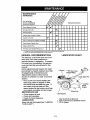
J_f_f
P,
L.,,o,,ES
,S,OOCOMPLE,E
Check
Engine
Change
7.."
I , ZfZ 'l
Oil
SERV'CEOATES
1_1.2
Oil Pivot Points
I1_
Inspect
Spark Arrester
Inspect
Air Screen
Clean
or Replace
Clean
Engine
Spark
_J_J
0il Level
Engine
Replace
l_f
/ Muffler
I_
V'
Air Cleaner
Cartridge
Cylinder Fins
Plug
1_2
if
I_
RH Gear Case Grease Fitting (1oz.)
I_
1 - Change more often when operating under a heavy road or in high ambient temperatures.
2 - Service more often when operating in dirty or dusty conditions.
GENERAL
RECOMMENDATIONS
LUBRICATION
The warranty on this tiller does not cover
items that have been subjected to
operator abuse or negligence. To receive
full value from the warranty, the operator
must maintain tiller as instructed in this
manual.
Some adjustments will need to be made
periodically to properly maintain your tiller.
All adjustments in the Service and
Adjustments section of this manual
should be checked at least once each
season.
• Once a year you should replace the
spark plug, clean or replace air filter,
and check tines and belts for wear. A
new spark plug and clean air filter
assure proper air-fuel mixture and help
your engine run better and last longer.
BEFORE EACH USE
CHART
"**RH Gear Case
Grease Fitting
Stake Pin
Shield
Hinges
* Wheel Hub
* Idler Bracket
• Check engine oil level.
• Check tine operation.
• Check for loose fasteners.
LUBRICATION
SAE 30 OR 5W-30 Motor Oil
** Refer to Maintenance "ENGINE" Section
*** EP #1 Grease
Keep unit well lubricated (See "LUBRICATION CHART")
13
• Refill engine with oil. See "CHECK
ENGINE OIL LEVEL" in the Operation
section of this manual.
_:_CAUTION: Disconnect spark plug wire
before performing any maintenance
(except carburetor adjustment) to prevent
accidental starting of engine.
Prevent fires! Keep the engine free of
grass, leaves, spilled oil, or fuel. Remove
fuel from tank before tipping unit for
maintenance.
Clean muffler area of all
grass, dirt, and debris.
Do not touch hot muffler or cylinder fins
as contact may cause burns.
011Drain
Plug_
Level
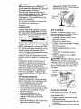
ENGINE
Oil Filler Plug
LUBRICATION
AIR CLEANER
Use only high quality detergent oil rated
with API service classification SF, SG or
SH. Select the oil's SAE viscosity grade
according to your expected temperature.
SAE VISCOSITY
=C -30°
-20 °
TEMPERATURE
GRADES
20"
RANGE ANTICIPATED
Service air cleaner cartridge every
twenty-five hours, more often if engine is
used in very dusty conditions.
• Loosen air cleaner screws, one on
each side of cover.
• Remove air cleaner cover.
• Carefully remove air cleaner cartridge.
Be careful. Do not allow dirt or debris to
fall into carburetor.
• Clean by tapping gently on a flat
surface.
• If very dirty or damaged, replace
cartridge.
• Clean and replace cover. Tighten
screws securely.
_,CAUTION"
Petroleum solvents, such as
kerosene, are not to be used to clean
cartridge. They may cause deterioration
of the cartridge. Do not oil cartridge. Do
not use pressurized air to clean or dry
cartridge.
30"
BEFORE NEXT OIL CHANGE
NOTE: Although multi-viscosity oils (5W30, 10W-30, etc.) improve starting in cold
weather, these multi-viscosity oils will
result in increased oil consumption when
used above 32°F (0°C). Check your
engine oil level more frequently to avoid
possible engine _lamage from running low
on oil.
Change the oil after every 50 hours of
operation or at least once a year if the
tiller is not used for 50 hours in one year.
Check the crankcase oil level before
starting the engine and after each five (5)
hours of continuous use. Add SAE 30
motor oil or equivalent. Tighten oil filler
plug securely each time you check the oil
level.
TO CHANGE ENGINE OIL
Air Cleaner
Air Cleaner
Determine temperature range expected
before oil change. All oil must meet API
service classification SF, SG or SH.
• Be sure tiller is on level surface.
• Oil will drain more freely when warm.
• Use a funnel to prevent oil spill on tiller,
and catch oil in a suitable container.
• Remove drain plug.
• Tip tiller forward to drain oil.
• After oil has drained completely,
replace oil drain plug and tighten
securely.
• Remove oil filler plug. Be careful not to
allow dirt to enter the engine.
\
COOLING
SYSTEM
Your engine is air cooled. For proper
engine performance and long life keep
your engine clean.
• Clean air screen frequently using a
stiff-bristled brush.
• Remove blower housing and clean as
necessary.
• Keep cylinder fins free of dirt and chaff.
14
SPARK PLUG
Blower
Housing
Screen
Replace spark plugs at the beginning of
each tilling season or after every 50 hour_
of use, whichever comes first. Spark pluc
type and gap setting are shown in
"PRODUCT SPECIFICATIONS".
TRANSMISSION
Once a season, lubricate the right hand
gear case grease fitting with 1 oz. of EP
#1 grease.
MUFFLER
CLEANING
Do not operate tiller without muffler. Do
not tamper with exhaust system. Damaged mufflers or spark arresters could
create a fire hazard. Inspect periodically
and replace if necessary. If your engine is
equipped with a spark arrester screen
assembly, remove every 50 hours for
cleaning and inspection. Replace if
damaged.
• Clean engine, wheels, finish, etc. of all
foreign matter.
• Keep finished surfaces and wheels free
of all gasoline, oil, etc.
• Protect painted surfaces with automotive type wax.
We do not recommend using a garden
hose to clean your unit unless the muffler,
air filter and carburetor are covered to
keep water out. Water in engine can
result in a shortened engine life.
TIRE CARE
_I_CAUTION: Disconnect spark plug wire
from spark plug and place wire where it
cannot come into contact with plug.
_iLCAUTION: When mounting tires,
unless beads are seated, overinflation
can cause an explosion.
• Maintain 20 pounds of tire pressure. If
tire pressures are not equal, tiller will
pull to one side.
• Keep tires free of gasoline or oil which
can damage rubber.
TO REMOVE WHEEL
• Place blocks under transmission to
keep tiller from tipping.
• Remove hairpin clip and clevis pin from
wheel,
• Remove wheel and tire.
• Repair tire and reassemble.
TILLER
TO ADJUST
HANDLE
HEIGHT
Select handle height best suited for your
tilling conditions. Handle height will be
different when tiller digs into soil.
• First loosen handle hex bolt.
• Handle can be positioned at different
settings between "HIGH" and "LOW"
positions.
• Retighten hex bolt securely after
adjusting.
Clevis Pin
(Low) Position
.!
Hairpin Clip
15
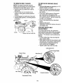
TO REMOVE
TO REPLACE
BELT
BELT GUARD
NOTE: For ease of removal, remove
hairpin clip and clevis pin from left wheel.
Pull wheel out from tiller about 1 inch.
• Remove two (2) screws from side of
belt guard.
• Remove hex nut and washer from
bottom of belt guard (located behind
wheel).
• Pull belt guard out and away from unit.
• Replace belt guard by reversing above
procedure.
Belt Guard
Screw
_
and
_._F
_\_>'./5:
"_
'_
(..Located
Behind
\
Hairpin Clip and Clevis Pin
GROUND
DRIVE
• Remove belt guard as described in "TO
REMOVE BELT GUARD".
• Remove old belt by slipping off engine
pulley first then remove from transmission pulley.
• Place new belt in groove of transmission pulley and into engine pulley.
BELT MUST BE IN GROOVE ON TOP
OF IDLER PULLEY. NOTE POSITION
OF BELT TO GUIDES.
• Check belt adjustment as described
below.
• Replace belt guard.
• Reposition wheel and replace clevis pin
and hairpin clip.
GROUND
DRIVE
ADJUSTMENT
BELT
For proper belt tension, the extension
spring should have about 5/8 inch stretch
when drive control bar is in "ENGAGED"
position. This tension can be attained as
follows:
• Loosen cable clip screw securing the
drive control cable.
• Slide cable forward for less tension and
rearward for more tension until about 5/
8 inch stretch is obtained while the
drive control bar is engaged.
• Tighten cable clip screw securely.
Cable Clip Screw
DriveControl Cable
Belt Guide "B"
Engine Pulley
More Tension
Idler Pulley
Transmission
Pulley
16
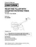
TINE REPLACEMENT
• To maintain the superb tilling performance of this machine the tines should
be checked for sharpness, wear, and
bending, particularly the tines which an
next to the transmission.
If the gap between the tines exceeds 3-1/2 inches
they should be replaced or straightene_
as necessary.
• New tines should be assembled.
Sharpened tine edges will rotate rearward from above.
_I,CAUTION: "13nes are sharp. Wear
gloves or other protection when handling
tines.
A badly worn tine causes your tiller to
work harder and dig more shallow. Most
important, worn tines cannot chop and
shred organic matter as effectively nor
bury it as deeply as good tines. A tine
this worn needs to be replaced.
NewTine
Trans_iion
Worn Tine
*-3-1/2" MAX
Counter "line
Rotation
Shear Pin
Sharp Edge
Shear Pin -_
Sharp Edge
Sharp
Edge
Hairpin Clip
Sharp
Edge
17
ENGINE
IDLE RPM ADJUSTMENT
Maintenance, repair, or replacement of
the emission control devices and systems, which are being done at the
customers expense, may be performed
by any non-road engine repair establishment or individual. Warranty repairs must
be performed by an authorized engine
manufacturer's
service outlet.
TO ADJUST CARBURETOR
• To adjust idle RPM, rotate throttle
linkage counterclockwise and hold
against stop while adjusting idle speed
adjusting screw to obtain 1750 RPM.
Release throttle linkage.
ACCELERATION
TEST
• Move throttle control lever from
"SLOW" to "FAST" position. If engine
hesitates or dies, turn idle needle valve
out (counterclockwise) 1/8 turn.
Repeat test and continue to adjust, if
necessary, until engine accelerates
smoothly.
High speed stop is factory adjusted. Do
not adjust or damage may result.
IMPORTANT: Never tamper with the
engine governor, which is factory set for
proper engine speed, overspeeding the
engine above the factory high speed
setting can be dangerous. If you think the
engine-governed high speed needs
adjusting, contact your nearest authorized
service center/department, which has the
proper equipment and experience to
make any necessary adjustments.
The carburetor has a high speed fixed jet
and has been preset at the factory and
adjustment should not be necessary.
However, minor adjustments may be
required to compensate for differences in
fuel, temperature, altitude or load. If the
carburetor does need adjustment,
proceed as follows.
Stop
Throttle Linkage
\
Idle Speed Adjusting
Screw
18
Immediately prepare your tiller for storage
at the end of the season or if the unit will
not be used for 30 days or more.
_iLCAUTION" Never store the tiller with
gasoline in the tank inside a building
where fumes may reach an open flame or
spark. Allow the engine to cool before
storing in any enclosure.
TILLER
• Clean entire tiller (See "CLEANING" in
the Maintenance section of this
manual).
• Inspect and replace belts, if necessary
(See belt replacement instructions in
the Service and Adjustments section of
this manual).
• Lubricate as shown in the Maintenance
section of this manual.
• Be sure that all nuts, bolts and screws
are securely fastened. Inspect moving
parts for damage, breakage and wear.
Replace if necessary.
• Touch up all rusted or chipped paint
surfaces; sand lightly before painting.
ENGINE
FUELSYSTEM
IMPORTANT: It is important to prevent
gum deposits from forming in essential
fuel system parts such as the carburetor,
fuel filter, fuel hose, or tank during
storage, also, experience indicates that
alcohol blended fuels (called gasohol or
using ethanol or methanol) can attract
moisture which leads to separation and
formation of acids during storage. Acidic
gas can damage the fuel system of an
engine while in storage.
• Drain the fuel tank.
• Start the engine and let it run until the
fuel lines and carburetor are empty.
• Never use engine or carburetor cleaner
products in the fuel tank or permanent
damage may occur.
• Use fresh fuel next season.
NOTE: Fuel stabilizer is an acceptable
alternative in minimizing the formation of
fuel gum deposits during storage. Add
stabilizer to gasoline in fuel tank or
storage container. Always follow the mix
ratio found on stabilizer container. Run
engine at least 10 minutes after adding
stabilizer to allow the stabilizer to reach
the carburetor. Do not drain the gas tank
and carburetor if using fuel stabilizer.
ENGINE
OIL
Drain oil (with engine warm) and replace
with clean oil. (See "ENGINE" in the
Maintenance section of this manual).
CYLINDER(S)
• Remove spark plug.
• Pour 1 ounce (29 ml) of oil through
spark plug hole into cylinder.
• Pull starter handle slowly several times
to distribute oil.
• Replace with new spark plug.
OTHER
• Do not store gasoline from one season
to another.
• Replace your gasoline can if your can
starts to rust. Rust and/or dirt in your
gasoline will cause problems.
• If possible, store your unit indoors and
cover it to give protection from dust and
dirt.
• Cover your unit with a suitable protective cover that does not retain moisture.
Do not use plastic. Plastic cannot
breathe which allows condensation to
form and will cause your unit to rust.
IMPORTANT: Never cover tiller while
engine and exhaust areas are still warm.
19
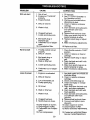
PROBLEM
Willnotstart
CAUSE
CORRECTION
1. Out of fuel.
2. Engine not "CHOKED"
properly.
3. Engine flooded.
4. Dirty air cleaner.
5. Water in fuel.
Clogged fuel tank.
7. Loose spark plug wire.
.
8. Bad spark plug or
improper gap.
9. Carburetor out of adjustment.
10.Oil soaked air filter.
Hard to start
1. Throttle control not set
properly.
2. Dirty air cleaner.
3. Bad spark plug or
improper gap.
4. Stale or dirty fuel.
5. Loose spark plug wire.
6. Carburetor
ment.
Loss of power
out of adjust-
1. Engine is overloaded.
2. Dirty air cleaner.
3. Low oil leveVdiffy oil.
4. Faulty spark plug.
5. Oil in fuel.
6. Stale or dirty fuel.
7. Water in fuel.
8. Clogged fuel tank.
9. Spark plug wire loose.
10.Dirty engine air screen.
11.Dirty/clogged muffler.
12.Carburetor out of adjutsment.
13.Poor compression.
2O
1. Fill fuel tank.
2. See "TO START ENGINE" in
the Operation section.
3. Wait several minutes before
attempting to staff.
4. Clean or replace aircleaner
cartridge.
5. Drain fuel tank and carburetor,
and refill tank with fresh
gasoline.
6. Remove fuel tank and clean.
7. Make sure spark plug wire is
seated properly on plug.
8. Replace spark plug or adjust
gap.
9. Make necessary adjustments.
10. Replace air filter.
1. Place throttle control in "FAST"
position.
2. Clean or replace air cleaner
cartridge.
3. Replace spark plug or adjust
gap.
4. Drain fuel tank and refill with
fresh gasoline.
5. Make sure spark plug wire is
seated properly on plug.
6. Make necessary adjustments.
1. Set depth stake and wheels for
shallower tilling.
2. Clean or replace aircleaner
cartridge.
3. Check oil level/change oil.
4. Clean and regap or change
spark plug.
5. Drain and clean fuel tank and
refill, and clean carburetor.
6. Drain fuel tank and refill with
fresh gasoline.
7. Drain fuel tank and carburetor,
and refill tank with fresh
gasoline.
8. Remove fuel tank and clean.
9. Connect and tighten spark
plug wire.
10.Clean engine air screen.
11 .Clean/replace muffler.
12.Make necessary adjustments.
13.Contact an authorized Sears
Service Center/Depaffment.
PROBLEM
Engine
overheats
CAUSE
CORRECTION
1. Low oil level/dirty oil.
2. Dirty engine air screen.
3. Dirty engine.
4. Partially plugged muffler.
5. Improper carburetor
adjustment.
1. Check oil level/change oil.
2. Clean engine air screen.
3. Clean cylinder fins, air screen
muffler area.
4. Remove and clean muffler.
5. Adjust carburetor to richer
position.
Excessive
bounce/difficult
handling
1. Ground too dry and hard.
1. Moisten ground or wait for
more favorable soil conditions
Soil balls up or
clumps
1. Ground too wet.
1. Wait for more favorable
soil conditions.
Engine runs but
tiller won't
move
1. Tine control is not engaged.
2. V-belt not correctly adjusted.
3. V-belt is off pulley(s).
1. Engage tine control.
2. Inspect/adjust V-belt.
3. InspectV-belt.
Engine runs but
labors when
tilling
1. Tilling too deep.
1. Set depth stake for shallower
tilling.
2. Check throttle control setting.
2. Throttle control not properly
adjusted.
3. Carburetor out of
adjustment.
3. Make necessary
adjustments
Tines Skip
over ground
1. Shear pin (s) broken.
1. Replace shear pin(s).
Hard to Shift
into gear
1. Gears not timmed.
1. Briefly engage drive control
bar and release or rock tiller
forward and backward until arc
able to shift gears.
Tiller shuts off
when drive
control bar
engaged
1. Shift lever set in between
counter rotating till position
and forward rotating till
position.
2. Tines jammed.
1, Shift to either counter rotating
till position or forward rotating
till position.
21
2, Clear tines.
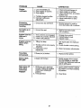
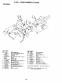
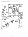
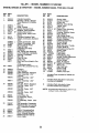
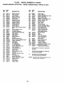
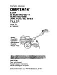
TILLER - - MODEL
NUMBER
917.293180
HANDLES
9
>
2
15
_.24
23
21
\
\
KEY PART
NO. NO.
2 141406
3 110673X
4 127254X
5 6712J
6 170388
7 110641X
9 72010520
10 8206H
11 STD624003
12 81328
13 110741X
14 109313X
15 110702X
16 STD523710
17 109229X
KEY PART
NO.
NO.
18 STD541437
19 19131611
21 150258
22 165197
23 170488
DESCRIPTION
Grip, Handle
Grommet, Handle
Bar, Drive Control Assembly
Cap, Vinyl
Panel,Control
Bushing, Split
*Bolt 5/16-18 x 2.50
Handle, Grip
*Clip, Hairpin
Bolt, Shoulder
Handle, Shift
Grommet, Rubber
Rod, Shift
*Bolt, Fin Hex 3/8-16 Unc x 1
Lock, Handle
24
25
26
27
9484R
73970500
110675X
73900400
DESCRIPTION
*Nut, Centerlock 3/8-16
Washer 13/32 x 1 x 11 Ga.
Handle, Assemble
Clip, Nyl BIk Cable
Screw, Hex, Washer Hd, Slotted
#10-24 x 1/2
Clip
Locknut, Hex, Flange
Clutch, Cable
*Nut, Hex Flange 1/4-20 Unc
* STANDARD HARDWARE
NOTE:
42
- - PURCHASE
All component dimensions
inches. 1 inch = 25.4 m
LOCALLY
given in U.S.
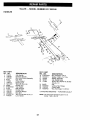
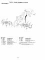
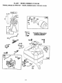
TILLER - - MODEL
NUMBER
917.293180
MAINFRAME, LEFT SIDE
3
1
/
36
16
35
31
30
28
3
23
15
24
KEY
NO.
PART
NO.
1
2
3
4
5
6
7
8
9
STD541431
STD551137
STD541037
170127
154734
110111X
STD532505
8700J
170488
10
11
12
13
14
9484R
STD551125
STD541025
23230506
110652X
15
16
19
21
23
STD551031
145102
12000028
156117
102190X
150750
795R
126875X
STD624003
24
25
KEY
NO.
DESCRIPTION
"Nut, Keps, Flange 5/16-18
*Washer, Lock 3/8
"Nut, Hex 3/8-16
Shield, Inner Belt Guard Rt
Screw Shift Lever
Lever, Shift
*Bolt, Carriage 1/4-20 x 1/2 Gr. 5
Plate, Shift indicator
Screw, Hex, Washer Head,
Slotted #10-24 x 1/2
Clip
*Washer, Lock 1/4
*Nut, Hex 1/4-20
*Screw, Set, 5/16-18 x 3/8
Spacer, Split
0.327 x 0.42 x 2.09
"Washer 11/32x11/16x16Ga.
Sheave,Transmission
Ring, Retaining
Spacer, Split0.327xO.42x1.220
Tire
Rim
Tire Valve
Rivet, Drilled
*Clip, Hairpin
26
27
28
29
30
31
32
33
34
35
36
37
38
39
40
41
43
44
46
64
PART
NO,
165501X558
132801
104679X
12000032
159229
102194X
102141X
STD523710
102173X
74760524
102331X
130812
74760544
140062
170488
73800400
69180
STD541431
73800400
19091016
*STANDARD
NOTE:
43
DESCRIPTION
Guard, Belt
Belt, V
Pulley, Idler
Ring, Klip
Bracket, Idler
Bolt, Fin Hex 3/8-16 Unc x 10
Shaft, Idler Arm
*Bolt, Hex 3/8-16 x 1
Counterweight, R.H.
Bolt, Hex 5/16-18 x 1-1/2
Bracket, Reinforcement, L.H.
Sheave, Engine
Bolt, Hex 5/16-18 UNC x 2-3/4
Cap
Screw Hex Wsh Hd #8-18 x I/2
Nut Lock Hex w/Ins 1/4-20 UNC
Nut Lock #10-24
Nut Lock Hex w/Ins 5/16-18 Unc
Nut Lock Hex w/Ins 1/4-20 UNC
Washer 9/32 x 5/8 x 16 Ga
HARDWARE
- - PURCHASE
All component dimensions
1 inch = 25.4 mm
LOCALLY
given in U.S. inches.
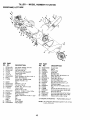
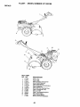
TILLER
- - MODEL
NUMBER
917.293180
MAINFRAME, RIGHT SIDE
15
KEY
NO.
5
6
7
8
9
11
12
13
PART
NO.
102332X
74760524
102173X
STD551137
STD541037
STD624003
126875X
102190X
150750
795R
KEY PART
NO. NO.
DESCRIPTION
14 STD541431
15 .....
Bracket, Reinforcment
Bolt, Hex 5/16-18 x 1-1/2
CounterWeight,
R.H.
*Washer, Lock 3/8
*Nut, Hex 3/8-16
*Clip, Hairpin
Rivet, Drilled
Tire
Rim
Tire Valve
DESCRIPTION
"Nut, Keps 5/16-18
Engine, (See Breakdown) Briggs
& Stratton Model No. 94202,Type
No. 0118-E1
* STANDARD HARDWARE
-. PURCHASE LOCALLY
NOTE: All component dimensions given in
U.S.inches. 1 inch = 25.4 mm
44
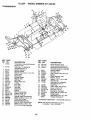
TILLER
- - MODEL
NUMBER
917.293180
TRANSMISSION
24
25
11
6
5
4
48
53
KEY PART
NO.
NO.
1 170354
2
165729
3 161963
4 5020J
5 1370H
6 137335
7 145101
6 4895H
9 154467
10 7392M
11 100371K
12 106160X
13 142145
14 8353J
15 1200O039
16 154466
18 4356J
23 102111X
24 STD551143
25 STD541143
27 143009
28 10639OX
29 102134X
30 150737
31 143008
32 106388X
33 102121X
KEY
NO.
DESCRIPTION
Transmission Assembly (includes
Key Nos. 2-54)
Gearcase, L H. w/Bea ring
(includes Key No. 4)
Gasket, Gearcase
Bearing, Needle
Washer Thrust5/8 x 1.10 x 1/32
Pinion, Input
Shaft, Input
Beadng, Needle
Washer, Seal
Ball, Steel
Spring, Shift, Fork
O-Ring
Arm, Shift
Fork, Shift
Ring, Klip
Shaft, Shift
Washer
Shaft, Reverse Idler
*Washer, Lock 7/16
*Nut, Hex 7/16-20
Bearing, Shaft, Ground Ddve
Spacer 0.765 x 1.125 x 1.23
Chain #35-50 Pitch
Ground Shaft Assembly
Beadng, Shaft, Ground Ddve
Spacer 0.70 x 1.O0 x 1.150
Sprocket and Gear Assembly
PART
NO.
34
35
36
102112X
102101X
154355
37
38
39
40
41
42
43
44
46
4422J
154356
105345X
170387
8358J
4220R
106146X
155236
170338
49
50
51
52
53
54
60
61
- -
132688
106147X
17720408
STD541031
165140
17720412
6855M
170366
6066J
DESCRIPTION
Shaft, Reduction (2nd}
Screw, Lock 5/16-18 x 3-1/2
Sprocket Assembly w/Bearing
(Includes Key Nos. 37 and 38)
Bearing, Needle
Sprocket, Tine
Gear, Cluster, Red 1st & 2rid
Spacer
Shaft, Reduction (1st)
Washer, Thrust
Spacer 1.01 x 1+75 x 0.760
Seal Asm OII
Gearcase, R.H. w/Beadng
(Includes Key No. 8)
Shaft, Tine
Chain, Roller #50+50 P{tch
Screw 1/4-20 x 1/2
*Nut, Hex 5/16-18
Bearing Kit, Tine Shaft
Screw Thd Cut 1/4-20 x 3/4
Fitting Grease
Split Spacer .52 x .64 x .562
Grease, Plastilube #1
• STANDARD HARDWARE
NOTE:
45
- - PURCHASE
All component dimensions given in
U.S.inches. 1 inch = 25.4 mm
LOCALLY
TILLER
- - MODEL
NUMBER
917.293180
TINE SHIELD
13
14
,j
28
24
19
21
KEY PART
NO.
NO.
1 73900500
3 8393J
4 12000036
5 STD533107
6 8394J
7 8392J
9 102152X558
10 72140508
11 STD541031
12 STD551131
13 STD533112
14 124343X
15 73900400
18 STD532512
19 102701X
20 STD541037
1
29
24
KEY
NO.
DESCRIPTION
Nut, Lock Hex Flange 5/16-18
Pin, Stake, Depth
Ring, Klip
*Bolt Carriage 5/16-18 x 3/4 Gr 5
Spring
Bracket, Latch
Shield, Tine
Bolt Rdhd Sqnk 5/16-18 UNC x 1
*Nut, Hex 5/16-18
*Washer, Lock 5/16
Bolt, Carriage 5/16-18 x 1-1/4
Bracket, Shield Tine
*Nut, Hex Flange 1/4-20 Uric
*Bolt, Carriage 1/4-20 x 1-1/4
Grip
*Nut, Hex 3/8-16
21
22
23
24
25
26
27
28
29
32
33
PART
NO.
102156X
74930632
4440J
STD532505
6712J
109227X
102686X558
120588X
104085X558
73220400
STD551125
DESCRIPTION
Stake, Depth
Bolt, Hex 3/8-16x2
Hinge
*Bolt, Carriage 1/4-20 x 1/2
Cap, Vinyl
Pad, Idler
Shield, Leveling
Pin, Hinge
Shield Asm Pnt Side
Nut Fin Hex 1/4-20 Uno
Washer Lock Hvy Helical 1/4
* STANDARD HARDWARE
NOTE:
46
- - PURCHASE LOCAL.LY
All component dimensions
inches. 1 inch = 25.4 mm
given in U.S.
TILLER
- - MODEL
NUMBER
917.293180
TINE ASSEMBLY
2
1
_
4
3
3
#
KEY PART
NO.
NO.
1 4459J
2 132673
3 6554J
4 STD624008
5 132721
6 73610600
7 STD551137
8 74610616
KEY PART
NO. NO.
9 4460J
10 132722
11 6555J
DESCRIPTION
Tine, Outer, L.H.
Pin, Shear
Tine, Inner, L.H.
Retainer, Spring Zinc
Assembly, Hub and Plate, L.H.
Nut, Hex 3/8-24
*Washer, Lock 3/8
Bolt, Hex 3/8-24 x 1
DESCRIPTION
Tine, Outer, RH.
Assembly, Hub and Plate, R.H.
Tine, Inner, R,H.
* STANDARD HARDWARE
NOTE:
47
- - PURCHASE
LOCALLY
All component dimensions given in U.S.
inches. 1 inch = 25.4 mm
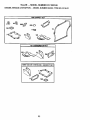
TILLER
- - MODEL
NUMBER
917.293180
DECALS
14
8
6
5
11
13
12
\
9
10
KEY PART
NO. NO.
DESCRIPTION
1
2
4
5
6
7
8
9
10
11
12
13
14
--
Decal, Logo
Decal, Logo
Decal, Caution, Drive Control
Decal, Hand Placement
Decal, Shift Indicator
Decal, Operation and Lubrication
Decal, Craftsman
Decal, Warning, Rotating Tines
Decal, Counter Rot. Tine
Decal, 3.75 HP
Decal, Tine Shield Wing Dora
Decal, Depth Stake
Decal, Control Speed
Manual, OwneC's (Eng/Span)
171670
170714
170712
120431X
170715
110719X
171920
120075X
157984
171803
162215
163094
165327
171023
48
TILLER - - MODEL NUMBER
917.293180
ENGINE, BRIGGS & STRATTON - - MODEL NUMBER 94202, TYPE NO. 0118-E1
I 20I*lgl
181
32
C
12
26
49
TILLER - - MODEL NUMBER
917.293180
ENGINE, BRIGGS & STRATTON - - MODEL NUMBER 94202, TYPE NO. 0118-E1
9Ol
--.
h
_.
97
,
95o
191
851
267
I 1036'LABEL
KIT-
EMISSION J
456
60_
456
332
689
304
5O
__
TILLER
- - MODEL
NUMBER
917.293180
ENGINE, BRIGGS & STRATTON - - MODEL NUMBER 94202, TYPE NO. 0118-E1
38
_
883
37C 1
lit REQUIRES SPECIALTOOLS
TO INSTALL. SEE REPAIR
INSTRUCTION MANUAL.
201
748
191_
@
181
_l--_J
621A_
51
TILLER - - MODEL NUMBER
917.293180
ENGINE, BRIGGS & STRATTON - - MODEL NUMBER 94202, TYPE NO. 0118-E1
358 GASKET
SET
121 CARBURETOR KIT
ii IIIHI
ii|
1095 VALVE OVERHAUL
52
GASKET SET
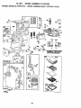
TILLER - - MODEL NUMBER
917.293180
ENGINE, BRIGGS & STRATTON - - MODEL NUMBER 94202, TYPE NO. 0118-E1
KEY PART
NO. NO.
1
2
KEY PART
NO. NO.
DESCRIPTION
DESCRIPTION
35
260552
Spring, Valve
37
224557
Guard, Fylwheel
38
94736
Screw, Hex
40
93312
Retainer, Valve Spring
45
230173
Tappet, Valve
46
493747
Gear, Cam
51
273113 (a** Gasket, Carb, Mounting
53
94523
Screw, Exhaust
55
499441
Housing, Rewind, Starter
58
281464
Rope, Starter
60
393152
Grip, Starter Rope
65
94904
Screw, Starter, Housing
73
225381
Screen, Rotating
90
499491
Carburetor Assembly
95
93499
Screw, Slotted
96
223793
Valve, Throttle
97
495313
Shaft and Lever, Throttle
109 497230
Choke, Shaft Kit
121 495606
Carburetor, Overhaul Kit
124 94616
Screw, Torx_
127 220352
Plug, Welch
127A 223789
Plug, Welch
144 499901
Pulley/Spring Assy.
152 260575
Spring Throttle Adjustment
153 490501
Collar, Bell, Crank
154 93527
Screw, Slotted
161 492797
Base, Air Cleaner
163 271935 _* Gasket, Air Cleaner
180 495377
Tank, Fuel
181 494559
Cap, Fuel Tank
190 94919
Screw, Torx_
!90A
94924
Screw, Torx_
191 272489
Gasket, Fuel Tank
494549
293706
Cylinder Assembly
Bushing, Cylinde (Special
Tools Required For Installation)
3
299819 *
Seal, Oil
5
214277
Head, Cylinder
7
272694 _* Gasket, Cylinder Head
8
495774
Breather, Valve Chamber
9
27549
O* Gasket, Valve Cover
10
94621
Screw, Sems, Valve Cover
Mount.
11
66578
Grommet, Breather Tube
12
270833 *
Gasket, Crankcase, Standard
.015"
270895
Gasket, Crankcase .005"
270896
Gasket, Crankcase .009"
13
94960
Screw, Cylinder Head
15
94387
P_ug,Oil Drain
(Opposite Carb Side)
16
495211
Crankshaft
499047
Key, Timing Gear Retaining
18
394820
Cover Assembly, Crankcase
19
293708
Bushing, Crankcase
20
299819
Seal, Oil
21
281658
Plug, Oil Filler
22
94607
Screw, Hex
94917
Stud, Hex Drive (Used In Pos.
4&5
of crankcase cover)
22A 94862
Screw, Hex, (Used In Pos. No.
1)
23
496278
Flywheel
24
222698
Key, Flywheel
25
498668
Piston Assembly, Standard
498669
Piston Assembly .010"
Oversize
498670
Piston Assembly .020"
Oversize
498671
Piston Assembly .030"
Oversize
26
498680
Ring Set, Piston, Standard
498681
Ring Set, Piston .010"
Oversize
498682
Ring Set, Piston .020"
Oversize
498683
Ring Set, Piston .030"
Oversize
27
26026
Lock, Piston Pin
28
298909
Pin Assembly, Piston,
Standard
298908
Pin Assembly, Piston .005"
Over
29
294367
Rod Assembly, Connecting
296079
Rod Assembly, Connecting,
.020" Undersize Crankpin
Bore
30
220670
Dipper, Connecting Rod
32
94699
Screw, Connecting Rod
33
296676
Valve, Exhaust (Includes
Retainer Number 93312)
34
296677
Valve, Intake
Indic_es Parts Included in Gasket Set
(494550)
indicates Parts Included in Carburetor
Overhaul Kit (495606)
O
Indicates Parts Included in Value
Overhaul Gasket Set (292638)
NOTE: All component dimensions given in U.S.
inches 1 inch = 25.4 mm
53
TILLER
- - MODEL
NUMBER
917.293180
ENGINE, BRIGGS & STRATTON - - MODEL NUMBER 94202, TYPE NO. 0118-E1
KEY
NO.
PART
NO.
200
201
202
209
211
216
222
257
298
300
304
305
306
307
495213
263174
262470
260041
263030
263188
499533
93543
220859
493288
499522
94786
224555
93758
308
332
333
334
337
356
358
363
373
383
392
393
394
432
433
434
435
455
456
459
526
527
528
529
535
536
542
608
609
611
512
621
224556
94877
496914
94731
802592
497298
495605
19203
94908
89838
262328
225058
272538
221377
93265
213963
93141
225502
281503
281505
94914
223786
491435
67838
491435
494279
94897
499706
265715
231067
391813
296110
KEY
NO.
DESCRIPTION
Blade, Governor
Link, Governor
Link, Throttle
Spring, Governor
Spring, Gov. Idle
Link, Choke
Bracket, Control
Screw, Hex Head
Locknut, Muftler
Muffler, Exhaust
Housing, Blower
Screw, Seres
Shield, Cylinder
Screw, Seres, Cylinder Shield
Mnt.
Cover, Cylinder Head
Nut, Flywheel
Armature, Magneto
Screw,Armature Mounting
Plug, Spark
Wire, Ground
Gasket Set
Puller, Flywheel
Nut, Hex
Wrench, Spark Plug
Spring, Fuel PumpOiaphragm
Screw, Carburetor
Diaphragm
Cap, Spring
Pin, Diaphragm
Cover, Diaphragm
Screw, Diaphragm Cover
Cup, Flywheel
Plate, Pawl Fdction
Pawl, Ratchet
Screw, Hex
Clamp, Breather Tube
Filter, Air
Grommet, Breather Tube
Filter, Air
Air Cleaner Kit
Screw, Hex Head
Starter Assembly, Rewind
Spdng, Choke
Line, Fuel
Tube, Pickup
Switch, Stop
PART
NO.
DESCRIPTION
Switch, Stop
Screw, Shoulder
Washer, Throttle Shaft, Foam
Elbow, Spark Plug
Spacer, Air Cleaner
Washer, Choke Shaft, Foam
Washer, Choke Shaft
Spring, Friction
Gear, 13ming
Screw, Hex.
Anchor, Spring
Terminal, Ignition Cable
Adapter Assembly, Muffler
Seat, Intake Valve
Seat, Exhaust Valve
Guide, Exhaust Valve
Guide, Intake Valve
(See Repair Manual)
Gasket, Muffler
883
272203
Plug
955
281227
Filter, Air
967
491588
Cover, Air Cleaner
968
495872
Screw, Slotted Hex,
969
490073
(Incl. Grommet)
Screw, Hex
971
94902
Seal, Throttle Shaft
987
398970
Spark Arrester
994
398067
Control, Throttle
995
497195
Label Kit, Emission
1036 499329
Gasket Set, Vavle Overhaul
1095 99669
2500 94202-0115Replacement Engine
-- -- 495914
Replacement Shortblock
621A
623
634
635
643
679
680
689
741
748
780
851
864
869
870
871
396847
94943
271853
66538
280737
270382
221839
260575
261533
99669
226029
493880
492232
211172
211291
231348
63709
Indicates Parts Included in Gasket Set
(494550)
**
Indicates Parts Included in Carburetor
Overhaul Kit (495606)
(_
Indicates Parts Included in Value
Overhaul Gasket Set (292638)
NOTE: Allcomponent dimensions given in U.S.
inches 1 inch = 25.4 mm
54
55
For repair of major brand appliances in your own home...
no matter who made it, no matter who sold it!
1-800-4-MY-HOMEsM Anytime,dayornight
iii!iiiii!iiiii_
(1-800-469-4663)
www.sears.com
•
To bring in products such as vacuums,
lawn equipment and electronics for repair call for
the location of your nearest Sears Parts & Repair Center.
:....
:
i
1 800 488 1222 Anytime dayor night
m
m
m
=
www sears corn
For the replacement parts, accessories and owner's manuals
that you need to do-it-yourself, call Sears PartsDirectSMt
1-800-366-PART 6 a.m.(1-800-366-7278)
11 p.m. CST,
7 days a week
i
www.sears. com/partsdirect
To purchase or inquire about a Sears Service Agreement:
1 800 827 6655
m
m
7am-5pm
Para pedir se rvicio de reparaci6n a domicilio,
.....
l=
CSTMon
Sat
=
Au Canada pou r serv ice en f ran_ais :
y para ordenar piezas con entrega a domicilio:
1 . 888 . SU . HOGAR sM
(1-888-784-6427)
S£ARS
=
1 8"r/-LE FOYER sM
(1-877-533-6937)
4
HomeCentral
s.
© Seam, Roebuck and Co.
171023
Rev. 5 2.17.00TR
® Registered Trademark/ TM Trademarkol Seam, Roebuckand Co.
® Marca Registrada / TM Marca de Fdbdca de Sears, Roebuck and Co.
Printed in U.S.A.