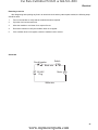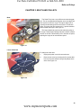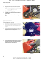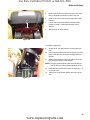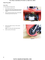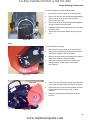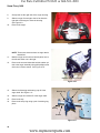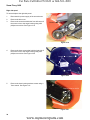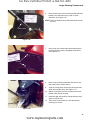
1
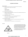
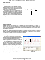
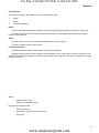
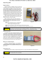
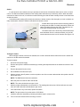
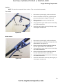
For Parts Call 606-678-9623 or 606-561-4983
Professional Shop Manual
Troy-Bilt Snow Flurry 1400
NOTE: These materials are for use by trained technicians who are experienced in the service and repair of outdoor power
equipment of the kind described in this publication, and are not intended for use by untrained or inexperienced individuals.
These materials are intended to provide supplemental information to assist the trained technician. Untrained or inexperienced individuals should seek the assistance of an experienced and trained professional. Read, understand, and follow all
instructions and use common sense when working on power equipment. This includes the contents of the product’s Operators Manual, supplied with the equipment. No liability can be accepted for any inaccuracies or omission in this publication,
although care has been taken to make it as complete and accurate as possible at the time of publication. However, due to
the variety of outdoor power equipment and continuing product changes that occur over time, updates will be made to these
instructions from time to time. Therefore, it may be necessary to obtain the latest materials before servicing or repairing a
product. The company reserves the right to make changes at any time to this publication without prior notice and without
incurring an obligation to make such changes to previously published versions. Instructions, photographs and illustrations
used in this publication are for reference use only and may not depict actual model and component parts.
© Copyright 2010 MTD Products Inc. All Rights Reserved
www.mymowerparts.com
For Parts Call 606-678-9623 or 606-561-4983
www.mymowerparts.com
For Parts Call 606-678-9623 or 606-561-4983
Table of Contents
Chapter 1: Introduction
Professional Service Manual Intent . . . . . . . . . . . . . . . . . . . . . . . . . . . . . . . . 1
Safety . . . . . . . . . . . . . . . . . . . . . . . . . . . . . . . . . . . . . . . . . . . . . . . . . . . . . . . 1
Fasteners . . . . . . . . . . . . . . . . . . . . . . . . . . . . . . . . . . . . . . . . . . . . . . . . . . . . 3
Assembly instructions . . . . . . . . . . . . . . . . . . . . . . . . . . . . . . . . . . . . . . . . . . . 3
Description of the Troy-Bilt Snow Flurry . . . . . . . . . . . . . . . . . . . . . . . . . . . . 3
Understanding model and serial numbers. . . . . . . . . . . . . . . . . . . . . . . . . . . 4
Chapter 2: Electrical
Basics of electricity . . . . . . . . . . . . . . . . . . . . . . . . . . . . . . . . . . . . . . . . . . . . . 5
Ohm’s law . . . . . . . . . . . . . . . . . . . . . . . . . . . . . . . . . . . . . . . . . . . . . . . . . . . . 5
Kirchhoff’s current law . . . . . . . . . . . . . . . . . . . . . . . . . . . . . . . . . . . . . . . . . . 6
Kirchhoff’s voltage law . . . . . . . . . . . . . . . . . . . . . . . . . . . . . . . . . . . . . . . . . . 6
AC electricity . . . . . . . . . . . . . . . . . . . . . . . . . . . . . . . . . . . . . . . . . . . . . . . . . . 6
Electric circuits . . . . . . . . . . . . . . . . . . . . . . . . . . . . . . . . . . . . . . . . . . . . . . . . 7
Types of circuits . . . . . . . . . . . . . . . . . . . . . . . . . . . . . . . . . . . . . . . . . . . . . . . 7
Circuit failures . . . . . . . . . . . . . . . . . . . . . . . . . . . . . . . . . . . . . . . . . . . . . . . . . 9
Tools . . . . . . . . . . . . . . . . . . . . . . . . . . . . . . . . . . . . . . . . . . . . . . . . . . . . . . . . 9
Switch . . . . . . . . . . . . . . . . . . . . . . . . . . . . . . . . . . . . . . . . . . . . . . . . . . . . . . 11
Circuit breakers . . . . . . . . . . . . . . . . . . . . . . . . . . . . . . . . . . . . . . . . . . . . . . 12
Motor . . . . . . . . . . . . . . . . . . . . . . . . . . . . . . . . . . . . . . . . . . . . . . . . . . . . . . 13
Switch box assembly . . . . . . . . . . . . . . . . . . . . . . . . . . . . . . . . . . . . . . . . . . 16
Servicing the switch box assembly . . . . . . . . . . . . . . . . . . . . . . . . . . . . . . . . 19
Returning to service . . . . . . . . . . . . . . . . . . . . . . . . . . . . . . . . . . . . . . . . . . . 21
Schematic . . . . . . . . . . . . . . . . . . . . . . . . . . . . . . . . . . . . . . . . . . . . . . . . . . . 21
Chapter 3: Belts and Pulleys
Belts . . . . . . . . . . . . . . . . . . . . . . . . . . . . . . . . . . . . . . . . . . . . . . . . . . . . . . . 23
Upper synchronous belt . . . . . . . . . . . . . . . . . . . . . . . . . . . . . . . . . . . . . . . . 24
Auger pulley . . . . . . . . . . . . . . . . . . . . . . . . . . . . . . . . . . . . . . . . . . . . . . . . . 26
Motor pulley . . . . . . . . . . . . . . . . . . . . . . . . . . . . . . . . . . . . . . . . . . . . . . . . . 27
Chapter 4: Auger Housing Components
Rubber auger spiral replacement . . . . . . . . . . . . . . . . . . . . . . . . . . . . . . . . . 29
Shave plate . . . . . . . . . . . . . . . . . . . . . . . . . . . . . . . . . . . . . . . . . . . . . . . . . . 29
Lower Discharge chute . . . . . . . . . . . . . . . . . . . . . . . . . . . . . . . . . . . . . . . . . 30
Upper discharge chute . . . . . . . . . . . . . . . . . . . . . . . . . . . . . . . . . . . . . . . . . 31
Auger . . . . . . . . . . . . . . . . . . . . . . . . . . . . . . . . . . . . . . . . . . . . . . . . . . . . . . 31
Left side panel . . . . . . . . . . . . . . . . . . . . . . . . . . . . . . . . . . . . . . . . . . . . . . . 34
Right side panel . . . . . . . . . . . . . . . . . . . . . . . . . . . . . . . . . . . . . . . . . . . . . . 36
Auger housing . . . . . . . . . . . . . . . . . . . . . . . . . . . . . . . . . . . . . . . . . . . . . . . 38
Handles . . . . . . . . . . . . . . . . . . . . . . . . . . . . . . . . . . . . . . . . . . . . . . . . . . . . 39
I
www.mymowerparts.com
For Parts Call 606-678-9623 or 606-561-4983
II
www.mymowerparts.com
For Parts Call 606-678-9623 or 606-561-4983
Introduction
CHAPTER 1: INTRODUCTION
Professional Service Manual Intent
This Manual is intended to provide service dealers with an introduction to the mechanical aspects of the Troy-Bilt
Snow Flurry.
Disclaimer: The information contained in this manual is correct at the time of writing. Both the product and the information about the product are subject to change without notice.
About the text format:
NOTE: is used to point out information that is relevant to the procedure, but does not fit as a step in the procedure.
•
1.
Bullet points: indicate sub-steps or points.
! CAUTION
Caution is used to point out potential danger to the technician, operator, bystanders, or surrounding property.
! WARNING
Warning indicates a potentially hazardous situation that, if not avoided, could result in death
or serious injury.
! DANGER
Danger indicates an imminently hazardous situation that, if not avoided, will result in death or
serious injury. This signal word is to be limited to the most extreme situations
Numbered steps indicate specific things that should be done, and the order in which they should be done.
1a.
Substeps will be lettered and nested within steps. Two or more substeps may be combined to describe
the actions required to complete a step.
Disclaimer: This manual is intended for use by trained, professional technicians.
•
Common sense in operation and safety is assumed.
•
In no event shall MTD be liable for poor text interpretation or poor execution of the procedures described
in the text.
•
If the person using this manual is uncomfortable with any procedures they encounter, they should seek
the help of a qualified technician or MTD Technical Support.
Safety
This Service Manual is meant to be used along with the Operator’s Manual. Read the Operator’s Manual and
familiarize yourself with the safety and operational instructions for the equipment being worked on. Keep a copy of
the Operator’s Manual for quick reference. Operator’s manuals may be viewed for free at the brand support website.
It will be necessary to have the complete model and serial number for the equipment.
1
www.mymowerparts.com
For Parts Call 606-678-9623 or 606-561-4983
Snow Flurry 1400
•
! CAUTION
Be prepared in case of emergency:
Keep a fire extinguisher nearby
Keep a first aid kit nearby
Keep emergency contact numbers handy
•
Replace any missing or damaged safety labels on shop equipment.
•
Replace any missing or damaged safety labels on equipment being serviced.
•
Grooming and attire:
! WARNING
Do not wear loose fitting clothing that may become entangled in equipment.
Long hair should be secured to prevent entanglement in equipment.
Jewelry is best removed.
•
Protective gear: includes, but is not limited to
Clear eye protection ................................ while working around any machinery
Protective gloves ..................................... where necessary
Armored footwear .................................... when working around any machinery
Hearing protection ................................... in noisy environments
Chemically resistant gloves ..................... when working with chemicals or solvents
Respirator ................................................ when working with chemical or solvents
Appropriate tinted eye protection............. when cutting or welding
Flame resistant headgear, jacket, chaps . when cutting or welding
•
Remember that some hazards have a cumulative effect. A single exposure may
cause little or no harm, but continual or repeated exposure may cause very serious
harm.
•
Clean spills and fix obviously dangerous conditions as soon as they are noticed.
•
Lift and support heavy objects safely and securely.
•
Be aware of your surroundings and potential hazards that are inherent to all power
equipment. All the labels in the world cannot protect a technician from an instant of
carelessness.
! CAUTION
2
www.mymowerparts.com
For Parts Call 606-678-9623 or 606-561-4983
Introduction
Fasteners
•
Most of the fasteners used on these snow throwers have metric thread sizes. For this reason, wrench
sizes are frequently identified in the text, and measurements are given in U.S. and metric scales.
•
If a fastener has a locking feature that has worn, replace the fastener or apply a small amount of releasable thread locking compound such as Loctite® 242 (blue).
•
Some fasteners, like cotter pins, are single-use items that are not to be reused. Other fasteners such as
lock washers, retaining rings, and internal cotter pins (hairpin clips) may be reused if they do not show
signs of wear or damage. This manual leaves that decision to the judgement of the technician.
Assembly instructions
•
Torque specifications may be noted in the part of the text that covers assembly. They may be summarized in tables along with special instructions regarding locking or lubrication. Whichever method is more
appropriate will be used. In many cases, both will be used so that the manual is handy as a quick-reference guide as well as a step-by-step procedure guide that does not require the user to hunt for information.
•
Lubricant quantity and specification may be noted in the part of the text that covers maintenance, and
again in the section that covers assembly. They may also be summarized in tables along with special
instructions. Whichever method is more appropriate will be used. In many cases, the information will be
found in several places in the manual so that the manual is handy as a quick-reference guide as well as a
step-by-step procedure guide that does not require the user to hunt for information.
•
The level of assembly instructions provided will be determined by the complexity of reassembly, and by
the potential for damage or unsafe conditions to arise from mistakes made in assembly.
•
Some instructions may refer to other parts of the manual for subsidiary procedures. This avoids repeating
the same procedure two or three times in the manual.
Description of the Troy-Bilt Snow Flurry
The Troy-Bilt Flurry 1400 is a compact, electric snow
thrower that is ideal for milder winters, smaller driveways
and lighter snowfalls.
Figure 1.1
3
www.mymowerparts.com
For Parts Call 606-678-9623 or 606-561-4983
Snow Flurry 1400
Understanding model and serial numbers
The model number of a the snow thrower described in this
manual is 31A-050-711. This manual is likely to carry useful information for a range of similar snow throwers that
may carry a variety of MTD and private brand names.
Figure 1.2
The break down of what the model number means is as follows:
•
31 - - - - - - - - - - - - - - - - - - - - - - - - - Indicates that this is a snow thrower.
•
- - A - - - - - - - - - - - - - - - - - - - - - - - - Sales level
•
- - - -050 - - - - - - - - - - - - - - - - - - - - - Indicates this is a Snow Flurry
•
- - - - - - - - 711- - - - - - - - - - - - - - - - - Customer number
The serial number is 1G150P00082. The serial number reads as follows:
•
1 - - - - - - - - - - - - - - - - - -Engineering level
•
- G - - - - - - - - - - - - - - - - -Month of production (G = July)
•
- - - 15 - - - - - - - - - - - - - - - -Day of the month
•
- - - - - 0 - - - - - - - - - - - - - - -Last digit of the year
•
- - - - - - P - - - - - - - - - - - - - -Plant it was built in
•
- - - - - - - - 0 - - - - - - - - - - - - -Assembly line number
•
- - - - - - - - - -0082 - - - - - - - - - -Number of unit built
Additional technical and service information may also be available to our company authorized service center personnel through our company corporate offices, regional parts distributors and regional service center field support
personnel. Please contact the designated support office in your area or our corporate offices directly should further
service information be needed.
MTD Products LLC
P.O. Box 368022
Cleveland, OH 44136
Telephone: (800) 800-7310
www.mtdproducts.com
4
www.mymowerparts.com
For Parts Call 606-678-9623 or 606-561-4983
Electrical
CHAPTER 2: ELECTRICAL
Basics of electricity
In order to diagnosis any electrical system there are few things the technician must understand:
•
Basic electrical values: voltage, current and resistance
•
Ohm’s law.
•
Kirchhoff’s current law.
•
Kirchhoff’s voltage law.
•
How the system is wired together.
The first electrical value to be discussed is Voltage.
•
Voltage is the “pressure” that electricity has. It is the amount of force pushing electrons through a circuit.
•
This pressure is measured in volts.
•
The capital letter “V” is used to represent volts.
The second electrical value is Current:
•
Current is the “flow” of electricity. It is the amount of electrons flowing in circuit.
•
The flow of current is measured in Amperes or Amps for short.
•
The capital letter “I” is used to represent Amps.
The third and final value is Resistance:
•
Resistance is the opposition to current flow. It is a restriction that slows down the flow of current.
•
Resistance is measured in Ohm’s.
•
The greek letter omega “Ω” or the capital letter “R” is used to represent Ohm’s.
Ohm’s law
Ohm’s law states that voltage is the product of resistance times current. It is written as V=I x R. An example of
how ohm’s law works goes like this: It takes 12 volt to push
2 amp through a resistance of 6 ohm (12=2 x 6). Ohm’s
law can be drawn in a triangle. When using the triangle,
cover the value to be found, and the two values left
exposed signify how to obtain that value. See Figure 2.1.
V
I
R
As an example if the “R” is covered, the “V” is over the
“I” which means V is divided by I. If the “V” is covered, “I”
and “R” is exposed, meaning IxR and so on.
Figure 2.1
5
www.mymowerparts.com
For Parts Call 606-678-9623 or 606-561-4983
Snow Flurry 1400
Kirchhoff’s current law
Kirchhoff’s current law deals with nodes. Nodes are
the junction of two or more wires or the junction of a wire to
a component. Kirchhoff’s current law states that what ever
current goes into a node must come out.
Node
5 Amps
3 Amps
As an example: Three wires are connected with a wire
nut. one wire has 5 amps going into the wire nut. The sum
of the current coming out of the other two wires must equal
5 amps. That could be 3 amps in one wire and 2 amps in
the other or it could be 2.5 amps in each wire, but the total
must be the same as the current coming in.
See Figure 2.2.
2 Amps
Figure 2.2
Kirchhoff’s voltage law
Kirchhoff’s voltage law deals with voltage drops. A voltage drop is the amount of voltage used up or “dropped” by a
resistance in the circuit. Ohm’s law stated that V = IxR, every component in a circuit has resistance, even the wires.
To push current through a resistance, it takes voltage. Kirchhoff’s voltage law states that the sum of all the voltage
drops equals the source voltage.
An example: a circuit has a battery of 12V, a light bulb that creates 3 ohms of resistance and there is 4 amps of current in the circuit. The wires are assumed to have 0 ohms, if the proper size wire is used and there is no corrosion in
the wire, the resistance will be too small to worry about. The light bulb uses 12 volts (4 amps x 3 ohms = 12 volts).
The battery has 12 volts that equals the 12 volts used by the light bulb.
AC electricity
AC electricity is used to provide electricity to homes
and businesses because it can be easily transmitted over
long distances. Some household products can run on
straight AC power while most will convert it to a usable DC
form internally.
AC wave form
1 Cycle
AC or alternating current is a current or voltage value
that varies with time and has an average value of zero. If
the current or voltage is observed using an oscilloscope,
the waveform will look like a sine wave. This means it will
be positive for awhile then it will be negative for awhile.
The time spent positive will equal the time spent negative.
Since it spends just as much time positive as negative, the
positive values cancel out the negative values leaving an
average value of zero. See Figure 2.3.
Since AC varies with time, the time or phase angle of
the waveform is needed to compute voltage and current.
This manual will not go into how to do this. AC is only mentioned here as a reference.
+
-
Figure 2.3
6
www.mymowerparts.com
For Parts Call 606-678-9623 or 606-561-4983
Electrical
Electric circuits
All circuits have some basic rules that must be followed:
1.
All circuits must have at least one voltage source. It could be a battery, an alternator or both.
2.
All circuits must have a load. To make a circuit without a load is the same as shorting out the power source. A
load could be:
•
a lamp
•
a motor
•
a resistor
•
a starter
3.
All circuits must have a complete path back to the voltage source. This is also known as having continuity.
4.
Most circuits have additional components like switches and fuses.
Types of circuits
There are three ways a circuit can be wired. They are:
•
Series
•
Parallel
•
Series/parallel
Series
• Series circuits are wired so that the current has
only one path to follow. See Figure 2.4.
Switch
Bulb
Battery
Figure 2.4
7
www.mymowerparts.com
For Parts Call 606-678-9623 or 606-561-4983
Snow Flurry 1400
Parallel
•
Parallel circuits are wired so that current has
multiple paths to follow. See Figure 2.5.
Figure 2.5
Series/parallel
•
Series/parallel circuits have some sections
wired in series and some in parallel.
See Figure 2.6.
Figure 2.6
8
www.mymowerparts.com
For Parts Call 606-678-9623 or 606-561-4983
Electrical
Circuit failures
There are three types of failures that can occur in an electrical circuit:
1.
Shorts
2.
Opens
3.
Increased resistance
Shorts
A short is when electricity takes a path that it was not designed to take bypassing a component in the circuit.
A common example of a short is the wire that chafed through. The bare copper will short the circuit when it
touches a ground source.
Opens
An open is when current can not complete its path back to the power source.
A common example of this is a blown fuse.
Increased resistance
Increased resistance is as the name implies, an increase in resistance.
Arguably the most common electrical failure, and the hardest to find, is when there is a loose connection or corrosion. It is not an open because there is some current that can get through, but the increase in resistance is enough
to affect the circuit
Tools
•
Digital volt ohm meter
•
Wiring or a schematic diagram.
Equipment that may be useful:
•
Fused jumper wires.
•
Hand tools to gain access to components.
•
Flash light.
9
www.mymowerparts.com
For Parts Call 606-678-9623 or 606-561-4983
Snow Flurry 1400
Digital multimeter
Digital Multi Meters or DMMs are the most useful tool
to trouble shoot any electrical system. Depending on the
model of DMM used, DMMs can measure Volts, Amps,
Ohms and more. DMMs are a must when working on circuits with solid state components (microchips). They have
very high impedance, that means they have very high
resistance and pull very little current from the circuit. Use
of analog equipment or test lights will pull enough current
to damage the microchips in the circuit. See Figure 2.7.
When measuring volts, always hook the meter in parallel with the circuit. That means do not disconnect the
component where measuring voltage.
When measuring current, the meter must be connected in series with the component to be measured. That
means opening the circuit and having the circuit go
through the meter.
Figure 2.7
NOTE: When measuring current, exceeding the
meters rating will damage the meter.
NOTE: The only exception to this is when using an inductive amp clamp.
NOTE: When measuring resistance, the component must be isolated from the circuit.
! CAUTION
The meter has its own power source to measure resistance. Connecting the meter to a component that has current going through it will damage the meter (usually beyond repair).
Inductive amp meter
An inductive amp meter, sometimes referred to as an
“amp clamp” or clamp meter, measures current following
through a wire by the magnetic field created around the
wire. Clamp meters are very important when dealing with
currents over 10 amps. A DMM typically can not measure
current over 10 amps. Clamp meters are also helpful
because they can read current in a circuit without opening
it up to hook the meter into the circuit. See Figure 2.8.
Wiring or a schematic diagram
A wiring or a schematic diagram is very important in
troubleshooting a circuit. The diagram shows how the circuit was designed and what paths the electricity is suppose to flow.
Figure 2.8
Fused jumper wires
Fused jumper wires are handy to help find bad grounds or to jump across switches for testing purposes.
! CAUTION
Only use fused jumper wires. If there is a short in the circuit, using an unfused jump could damage components in the circuit further.
10
www.mymowerparts.com
For Parts Call 606-678-9623 or 606-561-4983
Electrical
Switch
In order to bench test a switch, the way it operates must be known. All switches either open a circuit or close a
circuit. The difference between switches is their resting state and how many circuits they control. When the switch
controls more than one circuit, it could have one side normally open and the other normally closed. It could also have
all sides the same.
A switch that while resting (off) closes (has continuity or allows current to flow through it) a circuit is called a normally closed switch. When the switch is activated it will open the circuit.
COM
NO
A switch that is open (does not have continuity) when in
a resting state is called a normally open switch. When activated, the switch will close the circuit. The tabs for a normally open switch generally are unmarked.
The switch used on the snow flurry snow throwers has
three terminals. One is a common terminal, one is a NO
terminal and the last one is a NC terminal. See Figure 2.9.
NC
Figure 2.9
Testing the switch
When testing the switch, treat it as two switches; the common terminal and the NO terminal as one switch and
common to the NC terminal as another.
To test the switch:
1.
Disconnect the power supply.
2.
Remove and open the switch box assembly by following the steps described in the switch box section of this
chapter.
3.
Remove the switch from the circuit.
4.
Set the DMM to the ohms scale (Ω).
5.
With the switch in the off position; touch one probe to one of the common tabs and the other probe to the NC
tab for that circuit.
NOTE: The DMM should read zero resistance.
6.
Move the probe from the NC tab to the NO tab.
NOTE: The meter should show an open circuit.
7.
With the probes still attached, turn the switch on. The readings should reverse, NO should have zero resistance and a NC switch should indicate an open circuit.
8.
If the switch fails in any of the tests, replace the switch.
NOTE: The part number for just the switch is 725-05222.
9.
Install the switch box assembly by following the above steps in reverse order.
10.
Test run the snow thrower before returning to service.
11
www.mymowerparts.com
For Parts Call 606-678-9623 or 606-561-4983
Snow Flurry 1400
Circuit breakers
Circuit breakers are safety devices that open a circuit
when the current flow reaches a certain level. This helps to
prevent components from being damaged by the high current flow.
A circuit breaker is basically a switch. When current
flows through a circuit, it creates heat. The higher the current flow, the more heat that is created. As current flows
through a circuit breaker the contacts heat up. If the current heats the contacts enough, they will release the piece
used to jump across the contacts. That will open the circuit
and prevent current flow.
Some circuit breakers are self resetting, meaning that
as they cool down, the circuit is closed. The circuit breaker
on this snow thrower has a manual reset function. That
means that a button has to be pushed in to restore the
connection between the contacts. The circuit breaker may
have to cool down for a few minutes before the breaker
can be reset. See Figure 2.10.
Reset button
Figure 2.10
To test a circuit breaker
1.
Let the circuit breaker cool down for at least five
minutes and reset the breaker.
NOTE: If the circuit breaker will not reset, unplug
the wires from the breaker and let it cool
down for five minutes. If it still will not reset,
the breaker is bad and must be replaced.
2.
If not already done, remove the circuit breaker from
the circuit by unplugging the two wires.
NOTE: See the switch box section of this chapter
for the steps to open the switch box assembly.
3.
Check for continuity between the two tangs.
See Figure 2.11.
NOTE: If there is no continuity between the two
tangs, the breaker is bad and must be
replaced.
Figure 2.11
NOTE: The part number for just the circuit breaker
is 725-05221.
12
www.mymowerparts.com
For Parts Call 606-678-9623 or 606-561-4983
Electrical
Motor
The motor used on this snow thrower is an AC universal motor that is not serviceable. Before troubleshooting an
electric motor, check the easy stuff like the circuit breaker and make sure the snow thrower is plugged into a working
power source.
To test the motor:
Back probe the motor connections
Figure 2.12
8.
1.
Disconnect the power supply to the snow thrower.
2.
Move the snow thrower to a safe area.
3.
Remove the motor cover by following the procedures
described in the upper synchronous belt section of
Chapter 3: Belts and Pulleys.
4.
Set a DMM to the VAC (Volts AC) mode.
5.
Back probe the motor side of the motor harness connectors. See Figure 2.12.
NOTE: Paper clips can be inserted into the back side of
the connectors and used as extensions for the
DMM probes. See Figure 2.12.
6.
Connect the snow thrower to a power source.
7.
Operate the control bail of the snow thrower.
The DMM should read source voltage.
NOTE: If the DMM does not read source voltage, back trace the harness to find the problem before condemning the motor.
9.
If the DMM reads source voltage, but the motor does not turn:
9a.
Disconnect the power source.
9b.
Try to spin the auger by hand.
NOTE: The technician should be able to spin the motor by spinning the auger. If the motor does not spin,
check for binding loads in the belt drives. If the motor does spin, replace it.
13
www.mymowerparts.com
For Parts Call 606-678-9623 or 606-561-4983
Snow Flurry 1400
Motor Removal/replacement
To remove/replace a motor:
1.
Disconnect the power source.
2.
Remove the upper belt by following the procedures
described in Chapter 3: Belts and Pulleys.
3.
Remove the motor side harness clip using a #2 phillips screw driver. See Figure 2.13.
4.
Disconnect the motor harness.
Harness clip
Figure 2.13
5.
Remove the three motor screws using a 10 mm
wrench. See Figure 2.14.
Motor screws
NOTE: There is a spacer between the motor and
the side plate. A fourth screw will hold the
spacer in place when the motor is removed.
6.
Lift the motor and foam gasket out of the snow
thrower.
NOTE: If reusing the motor, keep the foam gasket
on it and protect the gasket from damage.
NOTE: If the foam gasket is damaged, it must be
replaced.
Figure 2.14
To install a motor:
1.
Mount the motor to the side plate so that the black
wire is on the top, front side of the motor and the
white wire is at the bottom, rear side of the motor.
See Figure 2.15.
NOTE: If the foam gasket is already attached to the
motor, align it in the groves in the housing.
Black wire
Figure 2.15
14
www.mymowerparts.com
For Parts Call 606-678-9623 or 606-561-4983
Electrical
Sealant
2.
Install the foam gasket.
3.
Apply a heavy bead of Terostat MS 939 or equivalent
sealant around the top half of the motor where the
gasket meets it. See Figure 2.16.
4.
Connect the motor harness.
5.
Install the harness clip.
6.
Install the belts and the motor cover by following the
procedures described in Chapter 3: Belts and Pulleys.
7.
Test run the motor in a safe area before returning it to
service.
Foam gasket
Figure 2.16
15
www.mymowerparts.com
For Parts Call 606-678-9623 or 606-561-4983
Snow Flurry 1400
Switch box assembly
To remove/replace a switch box assembly:
1.
Disconnect the power source.
2.
Slide the control bail out of the hole on the left side
of the handle bar. See Figure 2.17.
3.
Slide the control bail out of the switch box assembly.
Handle bar
Control bail
Figure 2.17
4.
Slip the harness out of the clip on the right side of
the middle handle. See Figure 2.18.
Clip
Harness
Figure 2.18
5.
Remove the two bolts that hold the switch box to the
handle bar using a 7/16” wrench. See Figure 2.19.
Bolts
switch box
Figure 2.19
16
www.mymowerparts.com
For Parts Call 606-678-9623 or 606-561-4983
Electrical
6.
Remove the three screws that hold the left side of the
motor cover to the snow thrower using a #2 phillips
screw driver. See Figure 2.20.
7.
Remove the screw that holds the rear of the top
motor cover to the bottom motor cover.
See Figure 2.21.
8.
Remove the three screws that hold the right side of
the motor cover to the auger housing using a #2 phillips screw driver. See Figure 2.22.
9.
Remove the motor cover from the right side of the
machine.
Screws
Figure 2.20
Screw
Figure 2.21
Screws
Figure 2.22
17
www.mymowerparts.com
For Parts Call 606-678-9623 or 606-561-4983
Snow Flurry 1400
10.
Remove the harness clip using a #2 phillips screw
driver. See Figure 2.23.
11.
Disconnect the harness from the motor harness.
12.
Install the switch box assembly by following the previous steps in reverse order.
13.
Test run the snow thrower in a safe area before
returning it to service.
Figure 2.23
18
www.mymowerparts.com
For Parts Call 606-678-9623 or 606-561-4983
Electrical
Servicing the switch box assembly
NOTE: DO NOT open the switch box during the warranty period. If there is a failure under warranty, replace
the entire switch box assembly.
To service the switch box:
Safety key
1.
Disconnect the power supply to the snow thrower.
2.
Remove the safety key.
3.
Remove the three housing screws using T-20 torx
driver. See Figure 2.24. Remove the switch box by
following the steps described in the switch box section of this chapter.
4.
Carefully peel back the label on the switch box until
the housing seam if fully exposed. See Figure 2.25.
5.
Carefully split the housing.
Screws
Figure 2.24
Seam
Figure 2.25
19
www.mymowerparts.com
For Parts Call 606-678-9623 or 606-561-4983
Snow Flurry 1400
•
Depressing the starter button lifts the torsion
spring so that it can catch the switch lever.
•
Squeezing the safety bail rotates the bail
socket, which in turn causes the torsion spring
to push against the switch lever.
•
The switch lever pushes the safety key into the
switch plunger, closing the contacts.
Safety key
Switch lever
NOTE: With the switch box open, the internal functions can be explained.
Torsion spring
Starter button
Bail socket
6.
Service the internal components.
Circuit breaker
To remove/replace the switch:
A
Remove the switch lever and pin.
B
Lift the switch out of the housing.
C
Disconnect the wires.
D
Install by following the previous steps in reverse
order.
Switch
Switch lever pin
To remove/replace the circuit breaker:
A
Pull the circuit breaker out of the housing.
NOTE: The circuit breaker is a tight fit in the housing.
B
Disconnect the wires.
C
Install by following the previous steps in reverse
order.
Figure 2.26
To remove/replace the harness:
A
Disconnect the wire that goes from the main harness to the switch.
B
Disconnect the wire on the circuit breaker closest to the main harness assembly.
C
Slide the main harness assembly out of the housing.
D
Install the main harness by following the previous steps in reverse order.
7.
Reassembly the switch box by following the previous steps in reverse order.
8.
Test run the snow thrower in a safe area before returning it to service.
20
www.mymowerparts.com
For Parts Call 606-678-9623 or 606-561-4983
Electrical
Returning to service
After diagnosing and repairing any fault in an electrical circuit and any other repairs needed, the following steps
should be taken:
1.
Test run the machine to verify that the condition has been repaired.
2.
Cycle the circuit at least ten times.
3.
Allow the machine to cool down for a couple of hours.
4.
Re-test the machine to verify the condition does not re-appear.
5.
If the condition does not re-appear, return the machine back to service.
Schematic
&LUFXLWEUHDNHU
6ZLWFK
%ODFNZLUH
9$&
3OXJ
0RWRU -
:KLWHZLUH
21
www.mymowerparts.com
For Parts Call 606-678-9623 or 606-561-4983
Snow Flurry 1400
22
www.mymowerparts.com
For Parts Call 606-678-9623 or 606-561-4983
Belts and Pulleys
CHAPTER 3: BELTS AND PULLEYS
Belts
Upper synchronous belt
Reduction pulley
The Snow Flurry has a very efficient snow throwing pattern. This is accomplished through the use a two stage, belt
drive system to drive the auger. The upper stage uses a
synchronous belt that goes from the motor to a reduction
pulley. This gives the drive system a 2.5:1 speed reduction
and increases the torque. See Figure 3.1.
The lower ribbed belt goes from the reduction pulley to
the auger. This belt has a spring load idler to hold a constant
tension on the belt. This belt has a 3.5:1 reduction in speed,
spinning the auger at its most efficient speed.
Lower ribbed belt
Figure 3.1
Lower ribbed belt
To change the lower belt:
1.
Unplug the power cord of the snow thrower.
2.
Remove belt cover by removing the five screws that
hold it to the snow thrower using a #2 phillips screw
driver. See Figure 3.2.
Screws
Figure 3.2
23
www.mymowerparts.com
For Parts Call 606-678-9623 or 606-561-4983
Snow Flurry 1400
3.
Move the idler pulley to relieve the belt tension.
NOTE: A 10mm wrench can be used for leverage
when moving the idler pulley.
See Figure 3.3.
4.
Slide the belt off of the pulleys.
5.
Install the belt by following the previous steps in
reverse order.
6.
Test run the snow thrower before returning it to service.
Figure 3.3
Upper synchronous belt
To remove/replace the upper belt:
1.
Disconnect the power supply of the snow thrower.
2.
Remove the lower belt by following the procedures
described in the lower ribbed belt section of this
chapter.
3.
Screws
Remove the three screws that hold the right side of
the motor cover to the auger housing using a #2
phillips screw driver. See Figure 3.4.
Figure 3.4
4.
Remove the screw that holds the front left corner of
the motor cover to the auger housing using a #2
phillips screw driver. See Figure 3.5.
Screw
Figure 3.5
24
www.mymowerparts.com
For Parts Call 606-678-9623 or 606-561-4983
Belts and Pulleys
5.
Remove the screw from the rear of the motor cover
using a #2 phillips screw driver. See Figure 3.6.
6.
Remove the motor cover from the right side of the
machine.
7.
Loosen the nut and bolt that the reduction pulley
rotates on using a 12mm wrench and a 13mm
wrench.
8.
Slide the belt off of the pulleys.
Screw
Figure 3.6
To install the upper belt:
9.
Slide the belt over the reduction and the motor pulleys.
10. Using a large flat head screw driver, gently pry on the
head of the reduction pulley bolt to apply tension to
the belt.
11.
While holding tension on the belt, tighten the reduction pulley nut using a 13mm wrench.
NOTE: The prying force applied to the bolt head will prevent the bolt from turning while tightening the nut.
Reduction pulley bolt
12. Install the lower belt and the covers by following 1 - 5
in reverse order.
13. Test run the snow thrower before returning it to service.
Motor
Figure 3.7
25
www.mymowerparts.com
For Parts Call 606-678-9623 or 606-561-4983
Snow Flurry 1400
Auger pulley
To remove/replace the auger pulley:
1.
Disconnect the power source.
2.
Remove the lower belt by following the procedures
described in the lower ribbed belt section of this
chapter.
3.
Block the auger by placing a piece of wood down
the discharge chute. See Figure 3.8.
Piece of wood
Figure 3.8
4.
Remove the pulley nut using a 17mm wrench.
See Figure 3.9.
17mm wrench
NOTE: The pulley nut has right hand threads.
5.
Slide the pulley off of the auger.
Figure 3.9
26
www.mymowerparts.com
For Parts Call 606-678-9623 or 606-561-4983
Belts and Pulleys
6.Inspect the key and the auger shaft keyway for damage.
Key
NOTE: If the key is damaged, inspect the auger for signs
of impact damage.
7.Install the pulley by following the previous steps in
reverse order.
8.Test run the snow thrower before returning it to service.
Figure 3.10
Motor pulley
To remove/replace the motor pulley:
Motor shaft
1.
Disconnect the power source.
2.
Remove the upper belt by following the procedures
described in upper synchronous belt section of this
chapter.
3.
Hold the motor’s rotor shaft by inserting a flat head
screw driver into the slot in the end of it, on the fan
side. See Figure 3.11.
4.
Unthread the motor pulley in a counter-clockwise
direction using a large pair of pliers. See Figure 3.12.
5.
Install the motor pulley by following the previous
steps in reverse order.
Figure 3.11
NOTE: Hand tighten the motor pulley onto the motor shaft.
Motor pulley
NOTE: DO NOT put a thread locking compound on the
threads. The pulley is self tightening and the compound will interfere with that.
6.
Test run the snow thrower in a safe area before
returning it to service.
Figure 3.12
27
www.mymowerparts.com
For Parts Call 606-678-9623 or 606-561-4983
Snow Flurry 1400
28
www.mymowerparts.com
For Parts Call 606-678-9623 or 606-561-4983
Auger Housing Components
CHAPTER 4: AUGER HOUSING COMPONENTS
NOTE: The snow flurry snow throwers have two components that are normal wear parts. They are the rubber
auger spirals and the shave plate. These components will need to be replaced from time to time.
Rubber auger spiral replacement
To replace the rubber auger spirals:
Spirals
1.
Disconnect the power supply of the snow thrower.
2.
Remove the nuts and bolts that hold the rubber spirals to the auger assembly using a #3 phillips screw
driver and a 10mm wrench. See Figure 4.1.
3.
Install the spirals by following the previous steps in
reverse order.
NOTE: Tighten the nuts and bolts until they start to compress the rubber.
NOTE: Over torquing the nuts and bolt can cause the bolt
head to pull through the rubber.
4.
Test run the snow thrower in a safe area before
returning it to service.
Figure 4.1
Shave plate
To replace the shave plate:
1.
Disconnect the power supply of the snow thrower.
2.
Lay the snow thrower down on its side.
3.
Remove the three screws that hold the shave plate to
the auger housing using a #2 phillips screw driver.
See Figure 4.2.
4.
Install the shave plate by following the previous steps
in reverse order.
5.
Test run the snow thrower in a safe area before
returning it to service.
Screws
Shave plate
Figure 4.2
Lower Discharge chute
29
www.mymowerparts.com
For Parts Call 606-678-9623 or 606-561-4983
Snow Flurry 1400
To remove/replace the lower discharge chute:
1.
Disconnect the power supply of the snow thrower.
2.
Remove the four screws that hold the front cover to
the auger housing using a #3 phillips screw driver.
See Figure 4.3.
Front cover
Figure 4.3
NOTE: The lower discharge chute has a spring
loaded detent ratchet pressing against it. As
the chute is pulled away from the auger
housing, this ratchet will fall out. See Figure
4.4.
3.
If replacing the lower discharge chute, remove the
upper discharge chute from the lower chute.
Detent ratchet
Figure 4.4
4.
Tip the snow thrower back so that the chute opening
is facing up.
5.
If necessary, insert the springs into the detent
ratchet.
6.
Apply a light coat of lithium grease to the teeth section of the detent ratchet.
7.
Install the detent ratchet and spring in the auger
housing so that the spring slide over the bosses in
the housing. See Figure 4.5.
8.
Insert the lower discharge chute into the auger
housing.
9.
Install the front cover.
10.
Test run the snow thrower before returning it to service.
Detent ratchet and springs
Bosses
Figure 4.5
Upper discharge chute
30
www.mymowerparts.com
For Parts Call 606-678-9623 or 606-561-4983
Auger Housing Components
To remove/replace the upper discharge chute:
1.
Disconnect the power supply of the snow thrower.
2.
Remove the lock nut and carriage bolt that attach the
upper chute to the lower chute using a 10mm
wrench. See Figure 4.6.
3.
Remove the wing nut and carriage bolt that attaches
the upper chute to the lower chute.
4.
Install the upper chute by following the previous steps
in reverse order.
5.
Test run the snow thrower before returning it to service.
Carriage bolt
Wing nut
Figure 4.6
Auger
To remove/replace the auger:
Screws
1.
Disconnect the power supply of the snow thrower.
2.
Remove the lower belt by following the procedures
described in Chapter 3: Belt and Pulleys.
3.
Remove the auger pulley by following the procedures
described in Chapter 3: Belt and Pulleys.
4.
Remove both bearing retainers by removing the
bearing retainer screws using a 7mm wrench.
See Figure 4.7.
5.
Remove the two screws that hold the right side panel
to the auger housing using a #2 phillips screw driver.
6.
Remove the two nuts and bolts that attach the lower
handle to the side panel using a pair of 10mm
wrenches.
7.
Rotate the right side panel away from the auger
housing.
Figure 4.7
Side panel
Figure 4.8
31
www.mymowerparts.com
For Parts Call 606-678-9623 or 606-561-4983
Snow Flurry 1400
8.
Gently bow out the right side of the auger housing.
9.
Slide the auger far enough to the left to allow the
right side of the auger to clear the housing.
See Figure 4.9.
10.
Remove the auger.
Figure 4.9
NOTE: These snow throwers have an auger that is
assembled.
11.
Mark the auger end mounts to identify which one is
the left and which one is the right.
12.
Remove the nuts and bolts that hold the rubber spirals to the auger assembly using a #3 phillips screw
driver and a 10mm wrench. See Figure 4.10.
Mark the auger end mounts
Figure 4.10
End mount
13.
Slide the left bearing and bearing cup off of the
auger shaft. See Figure 4.11.
14.
Slide the auger end mount off of the auger shaft.
15.
Remove the key.
16.
Remove the snap ring using a pair of retaining ring
pliers.
Bearing cup
Bearing
Washer
Figure 4.11
32
www.mymowerparts.com
For Parts Call 606-678-9623 or 606-561-4983
Auger Housing Components
17. Remove the screw and washer that retain the right
bearing on the auger shaft. See Figure 4.12.
18. Slide the right bearing and bearing cup off of the
auger shaft.
19. Slide the auger end mount off of the auger shaft.
20. Remove the key.
21. Remove the snap ring using a pair of retaining ring
pliers.
22. Install the auger by following the previous steps in
reverse order.
Screw and washer
Figure 4.12
NOTE: Apply a small amount of releasable thread locking
compound such as Loctite® 242 (blue) to the
screw that retains the right bearing.
23. Test run the snow thrower in a safe area before
returning it to service.
33
www.mymowerparts.com
For Parts Call 606-678-9623 or 606-561-4983
Snow Flurry 1400
Left side panel
To remove/replace the left side panel:
1.
Disconnect the power supply of the snow thrower.
2.
Remove the upper and lower belt by following the
procedures described in Chapter 3: Belt and Pulleys.
3.
Remove the auger pulley by following the procedures described in Chapter 3: Belt and Pulleys.
4.
Remove the reduction pulley using a 12mm wrench
and a 13mm wrench.
Shoulder spacer
NOTE: There is a shoulder spacer and a washer
under the reduction pulley. See Figure 4.13.
5.
NOTE: the washer is
already removed
Remove the motor by following the procedures
described in Chapter 2: Electrical.
Figure 4.13
6.
Remove the three bearing retainer screws using a
7mm wrench. See Figure 4.14.
Bearing retainer
screws
Figure 4.14
7.
Remove the screw that holds the roller axle to the
side panel using a 10mm wrench.
NOTE: A pair of locking pliers can be used to hold
the axle while removing the screw.
See Figure 4.15.
Screw
Locking pliers
Figure 4.15
34
www.mymowerparts.com
For Parts Call 606-678-9623 or 606-561-4983
Auger Housing Components
8.
Remove both of the nuts and bolts that hold the lower
handle to the side panel using a pair of 10mm
wrenches. See Figure 4.16.
NOTE: There are washers under the bolt head and under
the nuts.
Lower handle
Figure 4.16
9.
Screws
Remove the two screws that hold the side panel to
the auger housing using a #2 phillips screw driver.
See Figure 4.17.
10. Slide the side panel out from in between the lower
handle and the auger housing.
Figure 4.17
Motor mounting plate
11.
Nut
Pivot bolt
12. Remove the shoulder bolt, spring and the idler pulley
using a 16mm wrench and a 10mm wrench.
Shoulder bolt
13. Remove the idler bracket using a 10mm wrench and
a 22mm wrench.
Spacer
Spring
Remove the nut and bolt that holds the spacer and
motor mounting plate to the side panel using a pair of
10mm wrenches. See Figure 4.18.
14. Install the left side panel by following the previous
steps in reverse order.
15. Test run the snow thrower in a safe area before
returning it to service.
Figure 4.18
35
www.mymowerparts.com
For Parts Call 606-678-9623 or 606-561-4983
Snow Flurry 1400
Right side panel
To remove/replace the right side panel:
1.
Disconnect the power supply of the snow thrower.
2.
Remove the belt cover.
3.
Remove the screw that holds the front left corner of
the motor cover to the auger housing using a #2
phillips screw driver. See Figure 4.19.
Screw
Figure 4.19
4.
Remove the three screws that hold the right side of
the motor cover to the auger housing using a #2
phillips screw driver. See Figure 4.20.
Screws
Figure 4.20
5.
Remove the three bearing retainer screws using a
7mm wrench. See Figure 4.21.
Bearing retainer screws
Figure 4.21
36
www.mymowerparts.com
For Parts Call 606-678-9623 or 606-561-4983
Auger Housing Components
6.
Remove both of the nuts and bolts that hold the lower
handle to the side panel using a pair of 10mm
wrenches. See Figure 4.22.
NOTE: There are washers under the bolt head and under
the nuts.
Lower handle
Figure 4.22
7.
Remove the two screws that hold the side panel to
the auger housing using a #2 phillips screw driver.
See Figure 4.23.
8.
Remove the screw that holds the roller axle to the
side panel using a 10mm wrench.
9.
A pair of locking pliers can be used to hold the axle
while removing the screw. See Figure 4.15.
Screws
Figure 4.23
Screw
10. Slide the side panel out from in between the lower
handle and the auger housing.
11.
Install the right side panel by following the previous
steps in reverse order.
12. Test run the snow thrower in a safe area before
returning it to service.
Locking pliers
Figure 4.24
37
www.mymowerparts.com
For Parts Call 606-678-9623 or 606-561-4983
Snow Flurry 1400
Auger housing
To remove/replace the auger housing:
1.
Disconnect the power supply of the snow thrower.
2.
Remove the auger by following the procedures
described in the auger section of the chapter.
3.
Remove the motor cover by following the procedures described in the upper synchronous belt section of Chapter 3: Belts and Pulleys.
4.
Remove the lower discharge chute by following the
procedures described in the lower discharge chute
section of this chapter.
5.
Remove the shave plate by following the procedures described in the shave plate section of this
chapter.
6.
Remove the two carriage bolts and nuts that hold
the lower handle bar to the bottom of the auger
housing using a 10mm wrench. See Figure 4.25.
7.
Remove the two screws that hold the left side panel
to the auger housing using a #2 phillips screw
driver. See Figure 4.26.
8.
Slide the auger housing out of the snow thrower.
Carriage bolts
Figure 4.25
Screws
Figure 4.26
9.
Install the auger housing by following the previous
steps in reverse order.
Lower motor housing
NOTE: When installing the auger housing, make
sure the lower motor housing and the foam
gasket are in the slots in the auger housing.
See Figure 4.27.
10.
Test run the snow thrower in a safe area before
returning it to service.
Foam gasket
Figure 4.27
38
www.mymowerparts.com
For Parts Call 606-678-9623 or 606-561-4983
Auger Housing Components
Handles
NOTE: The handle is composed of three sections. They are serviceable separately.
Top section
Wing nuts
1.
Disconnect the power supply of the snow thrower.
2.
Remove the switch box assembly by following the
procedures described in Chapter 2: Electrical.
3.
Remove the two wing nuts and carriage bolts.
See Figure 4.28.
4.
Gently spread the upper handle section while sliding
it off of the snow thrower.
5.
Install the upper handle section by following the previous steps in reverse order.
1.
Disconnect the power supply of the snow thrower.
2.
Slip the harness out of the clip on the right side of the
middle handle. See Figure 4.29.
3.
Remove the two wing nuts and carriage bolts that
hold the upper handle to the middle handle.
4.
Gently spread the upper handle section while sliding
it off of the snow thrower.
5.
Remove the two wing nuts and carriage bolts that
hold the middle handle to the lower handle.
6.
Gently spread the middle handle section while sliding
it off of the snow thrower.
7.
Install the middle handle section by following the previous steps in reverse order.
Figure 4.28
Middle section
Clip
Harness
Figure 4.29
39
www.mymowerparts.com
For Parts Call 606-678-9623 or 606-561-4983
Snow Flurry 1400
Lower handle
1.
Disconnect the power supply of the snow thrower.
2.
Remove the two wing nuts and carriage bolts that
hold the middle handle to the lower handle.
3.
Gently spread the middle handle section while sliding it off of the snow thrower.
Wing nuts
Figure 4.30
4.
5.
Remove the nuts and bolts that hold the lower handle to the left side panels using a pair of 10mm
wrenches. See Figure 4.31.
Handle bolts
Remove the nuts and bolts that hold the lower handle to the right side panels using a pair of 10mm
wrenches.
Figure 4.31
6.
Remove the two carriage bolts and nuts that hold
the lower handle bar to the bottom of the auger
housing using a 10mm wrench. See Figure 4.32.
7.
Slide the lower handle off of the snow thrower.
8.
Install the lower handle by following the previous
steps in reverse order.
9.
Test run the snow thrower before returning it to service.
Carriage bolts
Figure 4.32
40
www.mymowerparts.com
For Parts Call 606-678-9623 or 606-561-4983
www.mymowerparts.com
For Parts Call 606-678-9623 or 606-561-4983
MTD Products Inc - Product Training and Education Department
FORM NUMBER - 769-06345
09/2010
www.mymowerparts.com